STU USDM GT28 Hybrid Stock Twin Turbos Installation Manual
23
Page | 1 STU USDM GT28 Hybrid Stock Twin Turbos Installation Manual Article written by Stu Hagen & Jeremy Blackwell/SpeedForSale Revised February 1, 2012 TABLE OF CONTENTS: Section 1: Disassembly of the turbo system Section 2: Health check of sequential operation system Section 3a: Reinstallation of the new turbo kit Section 3b: REINSTALLATION REVISIONS/NOTES/EDITS FOR INSTALLING THE OPTIONAL ‘Sub-4500 RPM Transition and Horsepower Upgrade Kit’ Section 4: Torque Specifications Section 5: Turbo sizing comparison Section 6: Pictorial parts list
Transcript of STU USDM GT28 Hybrid Stock Twin Turbos Installation Manual

P a g e | 1
STU USDM GT28 Hybrid Stock Twin Turbos
Installation Manual
Article written by Stu Hagen & Jeremy Blackwell/SpeedForSale
Revised February 1, 2012
TABLE OF CONTENTS:
Section 1: Disassembly of the turbo system
Section 2: Health check of sequential operation system
Section 3a: Reinstallation of the new turbo kit
Section 3b: REINSTALLATION REVISIONS/NOTES/EDITS FOR INSTALLING THE OPTIONAL
‘Sub-4500 RPM Transition and Horsepower Upgrade Kit’
Section 4: Torque Specifications
Section 5: Turbo sizing comparison
Section 6: Pictorial parts list

P a g e | 2
Section 1: Disassembly of the turbo system
The first task is to start removing all the parts/pipes/vacuum lines to allow access to the turbochargers. BE
SURE TO SOAK ALL TIGHT NUTS & BOLTS WITH ‘PB BLASTER’ PRIOR TO REMOVAL! This will cut down on
wasted time. Take your time and follow the repair manual step-by-step until you are down to only the turbos
and exhaust manifold remaining, then move on to SECTION 2.
If you need help getting to this part, or even the basics of the stock turbo system teardown, you can find step-
by-step instructions here: http://www.97supraturbo.com/1997%20Service%20Manual/Turbos.pdf

P a g e | 3
Section 2: Health check of sequential operation system
Upon removing all of the turbo system to reach the turbochargers, you need to check the health of the main
components that operate the turbo’s sequential system. These items include the VSVs (Vacuum Switching
Valves), actuators, and pressure tank. Failure to do so may result in the turbochargers not boosting properly
and you having to fully or partially disassemble the turbo system! Here is an enlarged diagram of the locations
of the items noted below:
http://www.speedforsale.com/images/uploaded/2JZVacuumSystem.JPG
Here are the items to check…
1. (IACV) Intake air control valve VSV: 38.5 ohms – 44.5 ohms
2. (EGCV) Exhaust gas control valve VSV: 38.5 ohms – 44.5 ohms
3. (WG) Wastegate control valve VSV: 22.0 ohms – 26 ohms
4. (EBV) Exhaust bypass control valve VSV: 22.0 ohms – 26 ohms
5. (IACV) Intake air control valve actuator: Apply 7.1psi of air pressure to the nipple and ensure the valve
opens.
6. (EGCV) Exhaust gas control valve actuator: Apply 7.1psi of air pressure to the nipple and ensure the valve
opens.
7. (WG) Wastegate control valve actuator: Cap off one nipple, and apply 17.4psi of air pressure to the other
nipple. The wastegate control valve should fully open.
8. (EBV) Exhaust bypass control valve VSV: Cap off one nipple, and apply 14.2psi of air pressure to the other
nipple. The exhaust bypass control valve should fully open.
9. Pressure tank: The actual pressure tank itself is located underneath the intake manifold and is a pain to get
to. So, using the picture below showing the vacuum hard lines going from the turbos over to the pressure
tank, check to make sure air flows from Port A through Port B, but NOT from Port B through Port A. Also apply
18 in/hg of vacuum to Port A, and ensure that vacuum doesn’t change after 1 minute. This test can also be
done by putting a vacuum cap on the hard line for Port B, and then pressurizing the hard line for Port A. After
1 minute, remove the vacuum cap off Port B and listen for air to be released.

P a g e | 4
Section 3a: Reinstallation of the new turbo kit
!!! IMPORTANT NOTE !!!
IF YOU HAVE PURCHASED AND ARE INSTALLING THE OPTIONAL ‘USDM GT28 Sub-4500 RPM
Transition and Horsepower Upgrade Kit’, THEN PLEASE REVIEW SECTION 3b items #I and #II
BELOW AND PERFORM THESE MODIFICATIONS NOW!
After removing all of the piping, heat shield, and oil and water lines, you have a choice of either taking off the
complete stock system manifold and all, or just remove the nuts that hold the OEM turbo’s onto the exhaust
center section (Turbine Outlet Elbow). There are 6 bolt/nuts on each turbo section. It is highly recommended
that you spray PB Blaster religiously the night before to loosen up the nuts. The same goes if you decide to
remove the manifold as well. See attachments for parts description and location. Also, when tearing things
down, I should mention about the parts that I expect to re-use when installing the new system.
• All 4 metal piping gaskets. 2 Inlets, 2 outlets
• Metal (EBT) Exhaust Bypass Tube gaskets (2)
• Multi Layer Turbine Outlet Elbow gaskets (2)
• 8 Hose clamps from the stock water lines. They will work with the new system.
• Oil inlet Banjo bolt 12MM from the block. The kit includes (4) new crush washers.
• Stock 1-7/8” ID IACV (Intake Air Control Valve) Rubber coupler hose. Needs to be cut down to 3-3/4”
from 4-3/4”
• Stock metal Exhaust manifold gaskets. Inside and outside.
• Exhaust outlet to Down Pipe metal “O” Rings (3)
These are the basic items with the turbo charger system. All other items associated with the removal are re-
used such as nuts and bolts. A list of replacement part numbers are listed below if you want to order all new
metal gaskets. I have given all the Toyota PN’s for these.
OEM Replacement Parts
#1 Turbo Housing Gasket 1 Toyota 17279-46020
#2 Turbo Housing Gasket 1 Toyota 17287-46020
12mm Banjo Bolt 2 Toyota 90401-12009
12mm crush washer 4 Toyota 90430-12026
12mm nuts 2 Toyota 90179-

P a g e | 5
Hose Clamps 6 Toyota 9047-28007
Compressor pipe gasket-
out 2 Toyota 17378-40010
Compressor pipe gasket-in 2 Toyota 17376-46010
Pipe coupler-Rubber 2 Toyota 17341-46070
Manifold gasket-Front 1 Toyota 17173-46040
Manifold gasket-Rear 1 Toyota 17198-46010
Manifold gasket-O ring 2 Toyota 17278-46011
These new GT28 turbo’s use mostly Banjo style bolts. The oil and water inlets and the water outlets are banjo
style. The Oil drain is a flange that incorporates a male -10AN for use with the metal braided -10AN lines. All of
the necessary parts are included.
INCLUDED PART LIST
• (2) -4AN Oil Inlet Braided Teflon hose. Female/Female. One 11” and one 12” long.
• (2) -10MM-Banjo Fitting with a -4AN male connection (for Oil Inlets)
• (2) -10MM x 1.25MM Banjo Bolt with (4) Crush Washers. (for Oil Inlets)
• (2) -4AN Swivel adapters-90 degree for Hose to 12MM Banjo adapter
• (2) -12MM-Banjo with -4AN male connection and (4) 12MM Crush Washers. You will be re-using the
OEM 12MM Banjo Bolt.
• (4) -14MM Banjo to 3/8” Barb water drain. (16) Crush Washers (4) 14MM x 1.5MM Banjo Bolts.
• 72” 3/8” Black Hi-Temp water hose line and (2) ½” hose clamps for water neck.
• (2) Custom Oil Drain adapters with -10AN Male fitting.
• (2) Paper Flange Gaskets
• (4) M6 x 1.00 - 22mm long Stainless Steel Hex bolts and washers. (for attaching the Flange)
• (1) -10AN Braided Teflon hose, 90*/Straight* ends, 10” Long for the #1 Turbo Drain to Block
• (1) -10AN Braided Teflon hose, 90*/Straight ends, 18” Long for the #2 Turbo Drain to Block
• (1) Custom Block flange with ½” NPT threaded insert. (Re-use OEM bolts)
• (1) Paper Flange Gasket
• (1) Earl’s 923110ERL -10AN to ½” NPT swivel adapter
• (1) 3-Way -10AN “Y” Adapter

P a g e | 6
• (2) New 2-1/4” Diameter Hi-Temp black silicone couplers and (2) new band clamps to replace the OEM
corrugated ones that are too short to re-use. (Intake Air Connector)
• (2) ½” x 1-1/4” Metal loom extensions (2) M6x1.0 bolts/washers/nuts
• Lengths of two different hose diameters for vacuum hoses
After assembling the new GT turbo’s onto the Turbine Outlet Elbow, you’re ready to install the complete unit
onto the engine or Manifold. But before you do this, you need to install all of the turbo fittings first. Install the
(2) Oil inlets (on top of the turbo). First the Crush washer, then the banjo, then the 2nd
crush washer, then the
Banjo bolt. Torque accordingly (see attached). Then attach the -4AN Oil line to the -4AN fitting on the Banjo.
Tighten it down. These will just “dangle” until the Turbo’s are installed onto the Head/motor.
Now install the bottom Oil Return Flange with the (2) M6x1.00-22mmBolts and (2) Washers. Make sure to
install the paper gasket first. Tighten down the M6 bolts. Screw on the -10AN Lines to the bottom of each
turbo. Install the angled side of the hose to the turbo. The straight end goes to the block. Otherwise you won’t
clear the EGCV or the Rear Exhaust housing. The 10” Long hose (45 degree ends) is for the #1 Turbo, and the
18” Long hose (90 degree end goes to Turbo, Straight end goes to drain Y-block) is for the #2 Turbo. Finger
tighten both of them down, and leave them to “dangle” down. Make sure that the #1 Turbo hose is angled
toward the engine and somewhat “over” the EGCV actuator. Position the #2 Turbo hose so it is pointed a little
toward the EBV actuator-> block. Also, make sure that these two are finger tight to the -10AN Flanges. You’re
going to need to move these just a little later when you install the block flange to line up the hoses.
Now install all (4) 14MM-3/8” Barb water line flanges. Crush washer, then the Banjo, then the other crush
washer, then the bolt. Tighten down. Try to point them straight down.
Now you’re ready to install the whole unit back on the Head/Engine. If you took the approach of just removing
and replacing the turbo sections only, rather than the manifold and all, then all of the above would still apply.
By installing all the lines prior, you will save time, and it will be much easier than trying to reach upside down if
already installed on the car.
First thing to do is to LOOSELY install both the Oil Inlet 12mm Banjo’s to the block (Washer, then Banjo, then
the 2nd
washer, then the bolt.) Then LOOSELY attach the 90 degree -4AN swivel adapter’s female end to the
12mm Banjo’s male end. Then LOOSELY attach the (2) -4AN Hoses’ female fittings to the 90 degree -4AN
swivel adapters. Once you have all of these oil feed fittings mocked up and in the correct positions for proper
clearance, TORQUE the oil feed banjo bolts to OEM spec, and firmly tighten all other connections. This
completes the Oil Inlets.
Remove the Oil Return Oil Tube bracket ‘stay’ from the OEM set up. This is the piece that held the OEM return
hose to the #2 Turbo ‘stay’. Wrap it around the -10AN line coming off the #2 turbo. Then later when finishing
the install, use the OEM Bolt and Nut to re-affix the bracket to the ‘stay’ and to the block. This holds the hose
so it doesn’t move around and keeps it somewhat in the OEM fashion.

P a g e | 7
Next is to insert the Earl’s -10AN to ½” NPT adapter into the custom Block flange. Warp the ½” NPT threaded
end with Teflon Tape. Tighten the Earl’s adapter down into the female ½” NPT block adapter. On the -10AN
Side of the Earl’s adapter, screw on the -10AN “Y” adapter. Now you’re ready in insert the (2) -10AN Lines to
this “Y” adapter. Keep all of the lines a little loose so you can line up everything. Once everything is properly
lined up you can start to tighten down all of the hose connections. The #2 Turbo hose will be nearly parallel to
the ground as it enters the “Y” adapter. The #1 turbo hose will be almost straight down into the “Y” adapter.
Now, install either your OEM EBV Tube, or the optional mandrel bent 1.5” EBV Tube included with the
optional SEQUENTIAL TRANSITION IMPROVEMENT KIT. You must install this larger tube AFTER you tighten
the #2 turbo’s -10an drain hose, otherwise you will not be able to tighten the hose to the fitting.
Once the turbos are on, you should install the water lines. The 2 metal water line tubes up front coming off
the water neck elbow are the water “IN” lines. One goes to the #1 turbo “outside” barb, and the other wraps
down and along the heat shield area to the #2 turbo barb on the “outside” of the turbo. The “Inside” barb on
both the turbos are connected to water “return” metal tubes. The one up front off the #1 turbo will be within
a few inches away from the barb. Same with the rear turbo drain. It will also be just a few inches away. Affix
one end, then route the hose until you reach the other connection point, and cut the hose to the appropriate
length. Attach the OEM clamps to the hose ends; one on the barb end and the other on the metal OEM line.
The only issue in all 4 lines is getting the water “Inlet” from the front water line all the way back to the #2
turbo routed in such a way that it doesn’t get in contact with any hot spots. Try snaking the hose through the
Vacuum lines that come off the metal loom down to the VSV’s. There is enough room there to slide it in
between and hold it in place so it routes back to the #2 turbo tightly. You can play around in finding the best
method.
Now you can install the heat shield.
!!! IMPORTANT NOTE !!!
IF YOU HAVE PURCHASED AND ARE INSTALLING THE OPTIONAL ‘USDM GT28 Sub-4500 RPM
Transition and Horsepower Upgrade Kit’, THEN PLEASE REVIEW SECTION 3b item #3 BELOW
AND PERFORM THIS HEAD SHIELD MODIFICATIONS NOW!
When you go to install the piping, this is where you’re going to need to cut down the IACV coupler hose to 3-
3/4”. Otherwise it will be too long. Re-use the clamps. Included in the kit are the 2 new black silicone pipe
couplers and clamps. You will now install these when you assembling the pipes back. These are shorter than
the stock ones, and the stock ones cannot be re-used or cut down. Make sure the clamps are facing up, and on
the fender side of the pipes. This way you can tighten them up where they won’t interfere with anything.
Once everything is back in place and when you go to install the metal Vacuum lines you will notice the bolt
holes will not line up. This is because these new turbos are about 3/8” shorter than the OEM ones (which is
why you are getting new rubber couplers and cutting down the IACV hose.) It is important that you line up the
rear bolt hole, but not the front two. This hole is by the IACV . If you do not line this hole up, then the vacuum
lines that go to the EBV in the rear will be too close to the fire wall and will not line up with the 2 vacuum
hoses. Where the other two mounting holes are located (up front by the “Y” pipe) you will be off by about ¾”.

P a g e | 8
One on the outside and another just behind and closer to the valve cover. You will need to install the small
plate adapters, which are about an inch long x ½” wide with 2 holes (supplied in the kit). One plate to attach to
the Loom with a bolt/nut/washer, and the other end for the OEM Bolt hole locations. This acts as a “bridge”
between the gap where they don’t line up. That should be sufficient to hold the loom in place. You will need to
cut a few vacuum lines shorter as well. This might be a good opportunity to install all new silicone lines. The
front 2 hard vacuum hoses around the “Y” front pipe will need cutting. The rear line going to the IACV and to
the rear metal line will also need a little cutting. All of which will be easy and self explanatory.
This is the overall view of both the -10AN Return lines and the two -4AN Oil inlet lines. The two oil inlets bolt
to the block with the stock 12mm banjo bolt. The kit includes 4 new Toyota crush washers.

P a g e | 9
The picture on the Right is the #2 Turbo oil drain line. It has a 90 degree on the turbo side and a straight on the
other. Notice how the stock hose C-Clamp (which is attached to the ‘stay’) is holding the hose in place. The
small hose to the right is the -4AN oil inlet for the #2 turbo.
The picture on the Left is the #1 turbo oil drain. PLEASE NOTE THAT THE #1 OIL DRAIN WAS REVISED, AND IS
NOW A 90 DEGREE ON THE TURBO SIDE AND STRAIGHT ON THE Y-ADAPTER SIDE! As mentioned previously,
finger tighten all the -10 Fittings so you can move the assembly around so it lines up to the 2 block bolts for
the return flange->block adapter.
At this point, please reference the pictures below for notes regarding the final button up work to complete the
installation.
!!! IMPORTANT NOTE !!!
IF YOU HAVE PURCHASED AND ARE INSTALLING THE OPTIONAL ‘USDM GT28 Sub-4500 RPM
Transition and Horsepower Upgrade Kit’ AND ARE INSTALLING THE SPRUNG OEM
WASTEGATE MODIFICATION, THEN PLEASE REVIEW SECTION 3b item #IV NOW! However, if
you have the Heavy Duty wastagate actuator instead of the Sprung OEM actuator, you can
disregard this step!
P a g e | 10

P a g e | 11

P a g e | 12

P a g e | 13
Section 3b: REINSTALLATION REVISIONS/NOTES/EDITS FOR INSTALLING
THE OPTIONAL ‘USDM GT28 Sub-4500 RPM Transition and Horsepower
Upgrade Kit’:
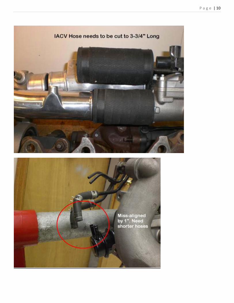
I- EBV Housing Port Work:
If you have chosen to port the EBV housings yourself, you need to note that this is a VERY important step to
ensure the full capability of the Transition Upgrade kit is reached. You need match both the ports AND the
inner diameter of the area down inside the housings to be the SAME size (or larger) as the inside diameter of
the upgraded EBV tube. Failure to do so will cause poor performance of the transition upgrade kit. Here are
before and after pictures of the stock EBV housings compared to the finished ported EBV housings:
Ported Lower Housing 1:
Ported Lower Housing 2:
Ported Upper Housing 1:
P a g e | 14
Ported Upper Housing 2:

P a g e | 15
II- EBV Actuator spacers & studs:
The included spacers, studs, and nuts (shown in the pictures below) are used to make the EBV actuator have
more tension and therefore not open as quickly. This allows the #1 turbocharger to build a higher peak boost
before the EBV opens to pre-spool the #2 turbocharger. This can be dangerous with the stock turbochargers
because they are so small and unreliable, but with the STU GT28 turbos being so robust and heavy duty it is no
problem! This will allow the car to make more torque below 4000 RPM while the #1 turbo is the only one
making boost. To install, you simply install the studs into the casting to which the EBV actuator bolts to. Then,
put the aluminum spacers between the actuator mounting bracket and the casting to which they bolt, and use
the provided nuts to hold it all together.

P a g e | 16
III- Heat shield spacers & studs:
This will give the heat shield enough room to clear the larger EBV tube. This is done the same way as the EBV
actuator spacers noted above. You simply use the included studs instead of the OEM bolts along with the
spacers over them, and then install the stock heat shield over them and tighten down the included nuts. You
will ONLY use the studs/spacers on the SIDE of the heat shield facing the passenger shock tower and A/C lines,
and will reuse the stock mounting bolts with NO spacers on the top of the shield. Also note that you will have
to push the shield a bit for this to fit, as it’s tight! You can see the location in the picture below:
P a g e | 17
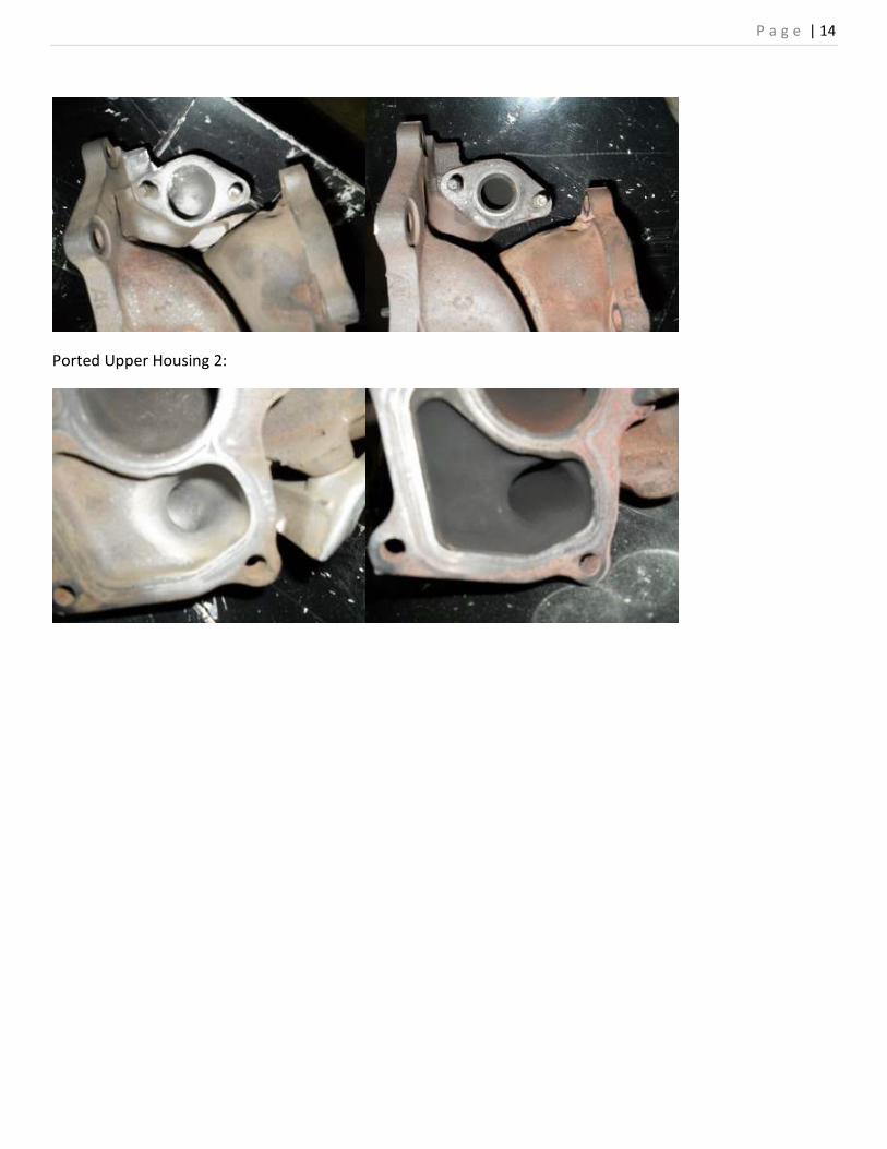
IV- Wastegate actuator spring modification:
ONLY REQUIRED IF YOU DO NOT HAVE THE HEAVY DUTY WASTEGATE ACTUATOR! THIS IS INTENDED FOR USE
WITH THE ADJUSTABLE OEM ACTUATOR.
This modification must be performed once the turbochargers are in the car. Using the pre-assembled spring
and bracket kit, this will install between the water pump housing and the wastegate puck flapper located at
the end of the actuator rod as shown in the pictures below.
First, here is a picture of the adjustable spring assembly. The end on the right bolts to the OEM water pump
housing, and the end on the left wraps around the wastegate puck flapper at the end of the rod. The wing nut
is used to adjust the tension on the wastegate puck. The tighter the tension, the higher the turbo boost
pressure. Having either this OR the Heavy Duty actuator is CRUCIAL to making the #1 turbo produce 12-14psi!
P a g e | 18
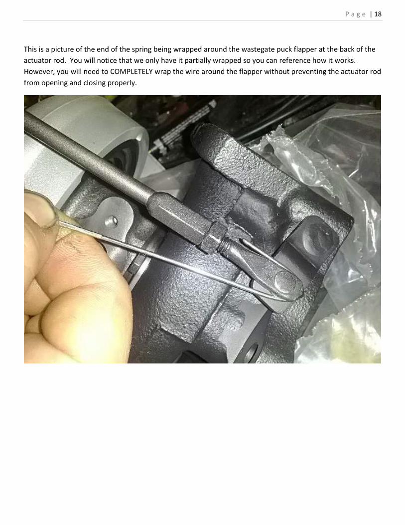
This is a picture of the end of the spring being wrapped around the wastegate puck flapper at the back of the
actuator rod. You will notice that we only have it partially wrapped so you can reference how it works.
However, you will need to COMPLETELY wrap the wire around the flapper without preventing the actuator rod
from opening and closing properly.

P a g e | 19
Here is a picture of the spring assembly installed on the car. This shows the bracket bolted to the water pump
housing, along with the spring with which you adjust the tension/boost.
P a g e | 20
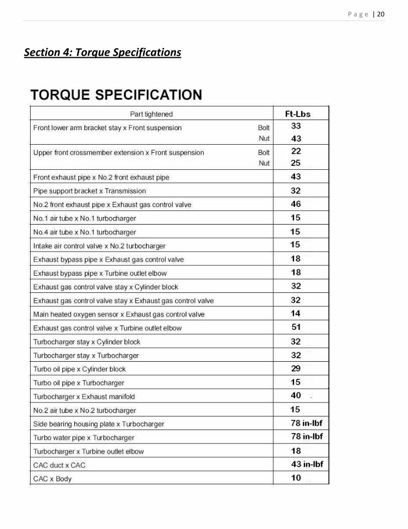
Section 4: Torque Specifications

P a g e | 21
Section 5: Turbo sizing comparison
Some basic comparisons between a stock CT12B and these new GT28R Garrett Cartridges:
P a g e | 22
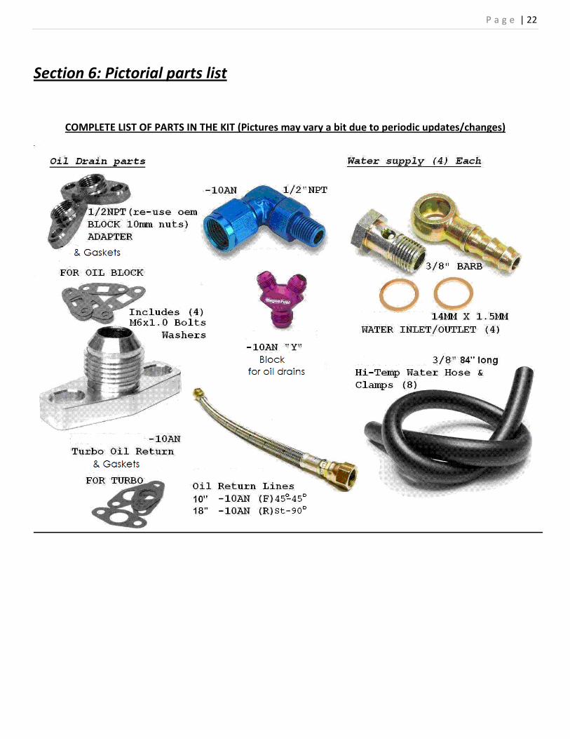
Section 6: Pictorial parts list
COMPLETE LIST OF PARTS IN THE KIT (Pictures may vary a bit due to periodic updates/changes)

P a g e | 23


![Turbos de Geometría Variable (Vtg)[1][1]](https://static.fdocuments.in/doc/165x107/55cf8e9a550346703b93d857/turbos-de-geometria-variable-vtg11.jpg)