STRUT JOINERS - Cesco.comPIPE/CONDUITCLAMPS & HANGERS B-Line’s beam attachments and pipe supports...
5
STRUT JOINERS 144 B766 SERIES STRAIGHT STRUT JOINER •Includes: 2 Cam Screws •Patented •Material: 12 Gauge (2.6) •Standard finish: ZN B768 SERIES TEE STRUT JOINER •Includes: 3 Cam Screws •Patented •Material: 12 Gauge (2.6) •Standard finish: ZN B769 SERIES CROSS STRUT JOINER •Includes: 4 Cam Screws •Patented •Material: 12 Gauge (2.6) •Standard finish: ZN B767 SERIES 90° ELBOW STRUT JOINER •Includes: 2 Cam Screws •Patented •Material: 12 Gauge (2.6) •Standard finish: ZN 4 1 /2” (114.3) 7 /8” (22.2) 4 1 /2” (114.3) 3 1 /16” (77.8) 2 5 /16” (58.7) 2 5 /16” (58.7) Wt./C Part No. For Channel Size Lbs. kg B767-11 B11 74 (33.5) B767-12 B12 56 (25.4) B767-22 B22 & B24 39 (17.7) B767-26 B26 41 (18.6) B767-32 B32 34 (15.4) B767-42 B42 27 (12.2) B767-52 B52 & B54 23 (10.4) B767-56 B56 25 (11.3) Wt./C Part No. For Channel Size Lbs. kg B766-11 B11 94 (42.6) B766-12 B12 72 (32.6) B766-22 B22 & B24 50 (22.7) B766-26 B26 53 (24.0) B766-32 B32 44 (19.9) B766-42 B42 34 (15.4) B766-52 B52 & B54 28 (12.7) B766-56 B56 31 (14.0) Wt./C Part No. For Channel Size Lbs. kg B768-11 B11 142 (64.4) B768-12 B12 112 (50.8) B768-22 B22 & B24 79 (35.8) B768-26 B26 79 (35.8) B768-32 B32 72 (32.6) B768-42 B42 62 (28.1) B768-52 B52 & B54 57 (25.8) B768-56 B56 60 (27.2) Wt./C Part No. For Channel Size Lbs. kg B769-11 B11 148 (67.1) B769-12 B12 120 (54.4) B769-22 B22 & B24 87 (39.4) B769-26 B26 93 (42.2) B769-32 B32 78 (35.4) B769-42 B42 65 (29.5) B769-52 B52 & B54 58 (26.3) B769-56 B56 62 (28.1) 4 1 /2” (114.3) 4 1 /2” (114.3) Reference page 136 for general fitting and standard finish specifications. U.L. Wire Fill Chart on pages 204-205. Channel, Combinations & Hole Patterns Channel Nuts & Hardware Fittings Beam Clamps Pipe Clamps Electrical Accessories Special Materials & Fiberglass Mini Channel & Fittings Concrete Inserts Slotted Angle Reference Data/Index
Transcript of STRUT JOINERS - Cesco.comPIPE/CONDUITCLAMPS & HANGERS B-Line’s beam attachments and pipe supports...

STRUT JOINERS
144
B766 SERIES STRAIGHT STRUT JOINER•Includes:
2 Cam Screws
•Patented
•Material: 12 Gauge (2.6)
•Standard finish: ZN
B768 SERIES TEE STRUT JOINER•Includes:
3 Cam Screws
•Patented
•Material: 12 Gauge (2.6)
•Standard finish: ZN
B769 SERIES CROSS STRUT JOINER•Includes:
4 Cam Screws
•Patented
•Material: 12 Gauge (2.6)
•Standard finish: ZN
B767 SERIES 90° ELBOW STRUT JOINER•Includes:
2 Cam Screws
•Patented
•Material: 12 Gauge (2.6)
•Standard finish: ZN
41/2”(114.3)
7/8”(22.2)
41/2”(114.3)
31/16”(77.8)
25/16”(58.7)
25/16”(58.7)
Wt./CPart No. For Channel Size Lbs. kgB767-11 B11 74 (33.5)
B767-12 B12 56 (25.4)
B767-22 B22 & B24 39 (17.7)
B767-26 B26 41 (18.6)
B767-32 B32 34 (15.4)
B767-42 B42 27 (12.2)
B767-52 B52 & B54 23 (10.4)
B767-56 B56 25 (11.3)
Wt./CPart No. For Channel Size Lbs. kgB766-11 B11 94 (42.6)
B766-12 B12 72 (32.6)
B766-22 B22 & B24 50 (22.7)
B766-26 B26 53 (24.0)
B766-32 B32 44 (19.9)
B766-42 B42 34 (15.4)
B766-52 B52 & B54 28 (12.7)
B766-56 B56 31 (14.0)
Wt./CPart No. For Channel Size Lbs. kgB768-11 B11 142 (64.4)
B768-12 B12 112 (50.8)
B768-22 B22 & B24 79 (35.8)
B768-26 B26 79 (35.8)
B768-32 B32 72 (32.6)
B768-42 B42 62 (28.1)
B768-52 B52 & B54 57 (25.8)
B768-56 B56 60 (27.2)
Wt./CPart No. For Channel Size Lbs. kgB769-11 B11 148 (67.1)
B769-12 B12 120 (54.4)
B769-22 B22 & B24 87 (39.4)
B769-26 B26 93 (42.2)
B769-32 B32 78 (35.4)
B769-42 B42 65 (29.5)
B769-52 B52 & B54 58 (26.3)
B769-56 B56 62 (28.1)
41/2”(114.3)
41/2”(114.3)
Reference page 136 for general fitting and standard finish specifications. U.L. Wire Fill Chart on pages 204-205.
Cha
nnel
, C
ombi
nati
ons
&H
ole
Pat
tern
sC
hann
el N
uts
& H
ardw
are
Fit
ting
sB
eam
Cla
mps
Pip
e C
lam
psE
lect
rica
lA
cces
sori
es
Spec
ial
Mat
eria
ls &
Fib
ergl
ass
Min
i Cha
nnel
& F
itti
ngs
Con
cret
eIn
sert
sSl
otte
d A
ngle
Ref
eren
ceD
ata/
Inde
x

PIPE/CONDUIT CLAMPS & HANGERS
B-Line’s beam attachments and pipe supports offered inthis section are designed to provide supports withoutdrilling or welding . A complete selection of beam clamps,pipe clamps, rollers, supports and accessories are designedfor use with B-Line channels and offer many installationadvantages.
Materials & Finishes*Pipe clamps, pipe hangers, beam clamps, brackets, androllers are made from low carbon steel strips, plates or rodunless noted.
*Unless otherwise noted.
Load DataThe load data published includes a safety factor of 5.0unless noted (safety factor = ratio of ultimate load to thedesign load).
Recommended TorqueFor Setscrews(unless noted)
*See chart on page 58 for bolt torque.
MetricMetric dimensions are shown in parentheses. Unlessnoted, all metric dimensions are in millimeters.
110
FinishCode Finish SpecificationPLN Plain ASTM A570 Gr. 33ZN Electro-Plated Zinc ASTM B633 SC3 Type IIIGRN Dura-Green TT-C-490BDCU Dura-Copper TT-C-490BHDG Hot-Dipped Galvanized ASTM A123SS4 Stainless Steel Type 304 ASTM A240SS6 Stainless Steel Type 316 ASTM A240AL Aluminum ASTM B209
Cha
nnel
, C
ombi
nati
ons
&H
ole
Pat
tern
sC
hann
el N
uts
& H
ardw
are
Fit
ting
sB
eam
Cla
mps
Pip
e C
lam
psE
lect
rica
lA
cces
sori
es
Spec
ial
Mat
eria
ls &
Fib
ergl
ass
Min
i Cha
nnel
& F
itti
ngs
Con
cret
eIn
sert
sSl
otte
d A
ngle
Ref
eren
ceD
ata/
Inde
x
Setscrew Size 1/4-20 3/8-16 1/2-13Foot/Lbs. 4 5 11
Nm 5 7 15
Setscrew Size 5/8-11 3/4-10Foot/Lbs. 21 34
Nm 28 46
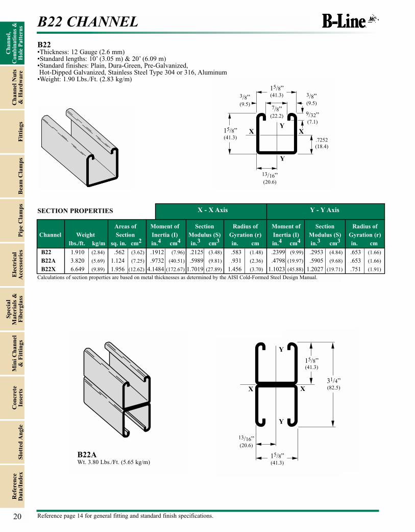
B22 CHANNEL
Areas of Moment of Section Radius of Moment of Section Radius ofChannel Weight Section Inertia (I) Modulus (S) Gyration (r) Inertia (I) Modulus (S) Gyration (r)
lbs./ft. kg/m sq. in. cm2 in.4 cm4 in.3 cm3 in. cm in.4 cm4 in.3 cm3 in. cm
B22 1.910 (2.84) .562 (3.62) .1912 (7.96) .2125 (3.48) .583 (1.48) .2399 (9.99) .2953 (4.84) .653 (1.66)
B22A 3.820 (5.69) 1.124 (7.25) .9732 (40.51) .5989 (9.81) .931 (2.36) .4798 (19.97) .5905 (9.68) .653 (1.66)
B22X 6.649 (9.89) 1.956 (12.62) 4.1484 (172.67) 1.7019 (27.89) 1.456 (3.70) 1.1023 (45.88) 1.2027 (19.71) .751 (1.91)
X - X Axis Y - Y Axis
B22•Thickness: 12 Gauge (2.6 mm) •Standard lengths: 10’ (3.05 m) & 20’ (6.09 m)•Standard finishes: Plain, Dura-Green, Pre-Galvanized,Hot-Dipped Galvanized, Stainless Steel Type 304 or 316, Aluminum
•Weight: 1.90 Lbs./Ft. (2.83 kg/m)
Calculations of section properties are based on metal thicknesses as determined by the AISI Cold-Formed Steel Design Manual.
15/8”(41.3)
15/8”(41.3)
15/8”(41.3)
31/4”(82.5)
13/16”(20.6)
13/16”(20.6)
15/8”(41.3)
.7252
(18.4)
3/8”(9.5)
3/8”(9.5)
9/32”(7.1)
7/8”(22.2)
X
Y
Y
XX
Y
Y
X
SECTION PROPERTIES
B22AWt. 3.80 Lbs./Ft. (5.65 kg/m)
20 Reference page 14 for general fitting and standard finish specifications.
Cha
nnel
, C
ombi
nati
ons
&H
ole
Pat
tern
sC
hann
el N
uts
& H
ardw
are
Fit
ting
sB
eam
Cla
mps
Pip
e C
lam
psE
lect
rica
lA
cces
sori
es
Spec
ial
Mat
eria
ls &
Fib
ergl
ass
Min
i Cha
nnel
& F
itti
ngs
Con
cret
eIn
sert
sSl
otte
d A
ngle
Ref
eren
ceD
ata/
Inde
x

B24 CHANNEL & COMBINATIONS
Areas of Moment of Section Radius of Moment of Section Radius ofChannel Weight Section Inertia (I) Modulus (S) Gyration (r) Inertia (I) Modulus (S) Gyration (r)
lbs./ft. kg/m sq. in. cm2 in.4 cm4 in.3 cm3 in. cm in.4 cm4 in.3 cm3 in. cm
B24 1.442 (2.15) .424 (2.74) .1494 (6.22) .1670 (2.74) .594 (1.51) .1857 (7.73) .2286 (3.75) .662 (1.68)
B24A 2.884 (4.29) .848 (5.47) .7514 (31.28) .4624 (7.58) .941 (2.39) .3713 (15.45) .4570 (7.49) .662 (1.68)
X - X Axis Y - Y Axis
B24•Thickness: 14 Gauge (1.9 mm) •Standard lengths: 10’ (3.05 m) & 20’ (6.09 m)•Standard finishes: Plain, Dura-Green, Pre-Galvanized,Hot-Dipped Galvanized, Stainless Steel Type 304 or 316, Aluminum
•Weight: 1.40 Lbs./Ft. (2.08 kg/m)
Calculations of section properties are based on metal thicknesses as determined by the AISI Cold-Formed Steel Design Manual.
15/8”(41.3)
15/8”(41.3)
13/16”(20.6)
.7304
(18.6)
3/8”(9.5)
3/8”(9.5)
9/32”(7.1)
7/8”(22.2)
X
Y
Y
X
SECTION PROPERTIES
24
B24AWt. 2.80 Lbs./Ft. (4.16 kg/m)
B24B Wt. 2.80 Lbs./Ft. (4.16 kg/m)
B24C Wt. 2.80 Lbs./Ft. (4.16 kg/m)
31/4”(82.5)
31/4”(82.5)
31/4”(82.5)
15/8”(41.3)
15/8”(41.3)
15/8”(41.3)
15/8”(41.3)
15/8”(41.3)
15/8”(41.3)
13/16”(20.6)
13/16”(20.6)
.730
(18.6)
XY
Y
Y Y
Y
Y
XX
X X
X
Reference page 14 for general fitting and standard finish specifications.
Cha
nnel
, C
ombi
nati
ons
&H
ole
Pat
tern
sC
hann
el N
uts
& H
ardw
are
Fit
ting
sB
eam
Cla
mps
Pip
e C
lam
psE
lect
rica
lA
cces
sori
es
Spec
ial
Mat
eria
ls &
Fib
ergl
ass
Min
i Cha
nnel
& F
itti
ngs
Con
cret
eIn
sert
sSl
otte
d A
ngle
Ref
eren
ceD
ata/
Inde
x

REFERENCE DATA
202
To Convert From To Multiply By To Convert From To Multiply By
Angle Lengthdegree radian (rad) 1.745329 x 10⁻² foot (ft) meter (m) 3.048000 x 10⁻¹
radian (rad) degree 5.729578 x 10+1 inch (in) meter (m) 2.540000 x 10⁻²
mil meter (m) 2.540000 x 10⁻⁵
Area inch (in) micrometer (mm) 2.540000 x 10+4
foot2 square meter (m2) 9.290304 x 10⁻² meter (m) foot (ft) 3.280840
inch2 square meter (m2) 6.451600 x 10⁻⁴ meter (m) inch (in) 3.937008 x 10+1
circular mil square meter (m2) 5.067075 x 10⁻¹⁰ meter (m) mil 3.937008 x 10+4
sq. centimeter (cm2) square inch (in2) 1.550003 x 10⁻¹ micrometer (mm) inch (in) 3.937008 x 10⁻⁵
square meter (m2) foot2 1.076391 x 10+1
square meter (m2) inch2 1.550003 x 10+3 Volumesquare meter (m2) circular mil 1.973523 x 10+9 foot3 cubic meter (m3) 2.831685 x 10⁻²
inch3 cubic meter (m3) 1.638706 x 10⁻⁵
Temperature cubic centimeter (cm2) cubic inch (in3) 6.102374 x 10⁻²
degree Fahrenheit degree Celsius t°C=(t°F -32)/1.8 cubic meter (m3) foot3 3.531466 x 10+1
degree Celsius degree Fahrenheit t°F=1.8t°C+32 cubic meter (m3) inch3 6.102376 x 10+4
gallon (U.S. liquid) cubic meter (m3) 3.785412 x 10⁻³
Forcepounds-force (lbf) newtons (N) 4.448222 x 10° Section Properties
section modulus S (in3) S (m3) 1.638706 x 10⁻⁵
moment of inertia I (in4) I (m4) 4.162314 x 10⁻⁷
modulus of elasticity E (psi) E (Pa) 6.894757 x 10+3
section modulus S (m3) S (in3) 6.102374 x 10+4
moment of inertia I (m4) I (in4) 2.402510 x 10+6
modulus of elasticity E (Pa) E (psi) 1.450377 x 10⁻⁴
METRIC CONVERSION CHART
To Convert From To Multiply ByBending Moment or Torquelbf • ft newton meter (N•m) 1.355818
lbf • in newton meter (N•m) 1.129848 x 10⁻¹
N•m lbf • ft 7.375621 x 10⁻¹
N•m lbf • in 8.850748
Massounce (avoirdupois) kilogram (kg) 2.834952 x 10⁻²
pound (avoirdupois) kilogram (kg) 4.535924 x 10⁻¹
ton (short, 2000 lb) kilogram (kg) 9.071847 x 10+2
ton (long, 2240 lb) kilogram (kg) 1.016047 x 10+3
kilogram (kg) ounce (avoirdupois) 3.527396 x 10+1
kilogram (kg) pound (avoirdupois) 2.204622
kilogram (kg) ton (short, 2000 lb) 1.102311 x 10⁻³
kilogram (kg) ton (long, 2240 lb) 9.842064 x 10⁻⁴
Mass Per Unit Lengthlb/ft kilogram per meter (kg/m) 1.488164
lb/in kilogram per meter (kg/m) 1.785797 x 10+1
kg/m lb/ft 6.719689 x 10⁻¹
kg/m lb/in 5.599741 x 10⁻¹
Mass Per Unit Volumelb/ft3 kilogram per cubic meter (kg/m3) 1.601846 x 10+1
lb/in3 kilogram per cubic meter (kg/m3) 2.767990 x 10+4
kg/m3 lb/ft3 6.242797 x 10⁻²
kg/m3 lb/in3 3.612730 x 10⁻⁵
lbs/ft3 lbs/in3 5.787037 x 10⁻⁴
Mass Per Unit Arealb/ft2 kilogram per square meter (kg/m2) 4.882428
kg/m2 pound per square foot (lb/ft2) 2.048161 x 10⁻¹
Pressure or Stresslbf/in2 (psi) pascal (Pa) 6.894757 x 10+3
kip/in2 (ksi) pascal (Pa) 6.894757 x 10+6
lbf/in2 (psi) megapascals (MPa) 6.894757 x 10⁻³
pascal (Pa) pound-force per square inch (psi) 1.450377 x 10⁻⁴
pascal (Pa) kip per square inch (ksi) 1.450377 x 10⁻⁷
megapascals (MPa) lbf/in2 (psi) 1.450377 x 10+2
Abbreviations
Defl. = Deflection
S.F. = Safety Factor
Ft. = Feet
Pre-galv. = Pre-galvanized Steel
K Factor = Deflection Divided
by load in Lbs./Ft.
o.c. = On Center
PVC = Poly Vinyl Chloride
In. = Inch
psi = Pounds per Square
Inch
wt./c = Weight pre 100 pieces
Metric Symbols
m = meter
cm = centimeter
mm = millimeter
µm = micrometer
kg = kilogram
N = newton
kN = kilonewton
Pa = pascal
MPa = megapascal
Cha
nnel
, C
ombi
nati
ons
&H
ole
Pat
tern
sC
hann
el N
uts
& H
ardw
are
Fit
ting
sB
eam
Cla
mps
Pip
e C
lam
psE
lect
rica
lA
cces
sori
es
Spec
ial
Mat
eria
ls &
Fib
ergl
ass
Min
i Cha
nnel
& F
itti
ngs
Con
cret
eIn
sert
sSl
otte
d A
ngle
Ref
eren
ceD
ata/
Inde
x