Structures Bulletin - Dayton Aerospace
35
DISTRIBUTION A. Approved for public release; distribution unlimited. EN-SB-08-012 Rev. C, Page 1 of 35 Number: EN-SB-08-012, Revision D Date: February 2018 Subject: In-Service Inspection Crack Size Assumptions for Metallic Structures References: 1. MIL-STD-1530D, Aircraft Structural Integrity Program, 13 October 2016. 2. JSSG-2006, Department of Defense Joint Service Specification Guide, Aircraft Structures, 30 October 1998. 3. MIL-HDBK-1823A, Nondestructive Evaluation System, Reliability Assessment, 7 April 2009. 4. J. Brausch, L. Butkus, D. Campbell, T. Mullis and M. Paulk, Recommended Processes and Best Practices for Nondestructive Inspection of Safety-of-Flight Structures, AFRL-ML- WP-TR-2009-4373, Air Force Research Laboratory, Wright-Patterson AFB, OH, Oct 2008. 5. EZ-SB-15-002, Requirements for NDI Procedure Development, Validation and Verification for Aircraft Structural Inspections During Operations and Support Phase. 6. T.O. 33B-1-2, Nondestructive Inspection General Procedures and Process Controls. 7. T.O. 33B-1-1, Nondestructive Inspection Methods, Basic Theory. 8. D. Palumbo, Probability of Detection Studies for Nondestructive Inspection Facilities Final Report, Contract Number F09603-01-D-0207, Karta Technologies, San Antonio, TX, 31 March 2006. 9. Ripudaman Singh, Three Decades of NDI Reliability Assessment, Report No. Karta-3510- 99-01, Karta Technologies, San Antonio, TX 78249, May 2000. 10. W. H. Lewis, B.D. Dodd, W.H. Sproat, J.M. Hamilton, Reliability of Nondestructive Inspections – Final Report, Lockheed-Georgia Co, Report No. SA-ALC/MME 76-6-38-1, Dec 1978. 11. D. Palumbo, D Earnest, Probability of Detection (POD) Studies for Nondestructive Inspection (NDI) Facilities Revision to Final Report, contract number: F09603-01-D-0207-SD05, Karta Technologies, San Antonio, TX 78249.3 Oct 2005. 12. M. Bode, F. Spencer, Air Force Research Lab Quality Assurance Proficiency Assessment Final Report, Sandia Laboratories, Albuquerque, NM, July 2007. 13. J. Brausch, Capability Estimation for Rotary Bolt hole Eddy Current Inspection of Titanium, Report Number AFRL/RXS 08-047, June 2008. 14. J. Brausch, Capability Estimation for Rotary Bolt hole Eddy Current of Aluminum Structures, Report Number AFRL/RXS 08-068, Sept 2008. Structures Bulletin AFLCMC/EZ Bldg 28, 2145 Monahan Way WPAFB, OH 45433-7017 Phone 937-255-5312
Transcript of Structures Bulletin - Dayton Aerospace

DISTRIBUTION A. Approved for public release; distribution unlimited.
EN-SB-08-012 Rev. C, Page 1 of 35
Number: EN-SB-08-012, Revision D Date: February 2018 Subject: In-Service Inspection Crack Size Assumptions for Metallic Structures References: 1. MIL-STD-1530D, Aircraft Structural Integrity Program, 13 October 2016. 2. JSSG-2006, Department of Defense Joint Service Specification Guide, Aircraft Structures,
30 October 1998. 3. MIL-HDBK-1823A, Nondestructive Evaluation System, Reliability Assessment, 7 April 2009. 4. J. Brausch, L. Butkus, D. Campbell, T. Mullis and M. Paulk, Recommended Processes
and Best Practices for Nondestructive Inspection of Safety-of-Flight Structures, AFRL-ML-WP-TR-2009-4373, Air Force Research Laboratory, Wright-Patterson AFB, OH, Oct 2008.
5. EZ-SB-15-002, Requirements for NDI Procedure Development, Validation and Verification for Aircraft Structural Inspections During Operations and Support Phase.
6. T.O. 33B-1-2, Nondestructive Inspection General Procedures and Process Controls. 7. T.O. 33B-1-1, Nondestructive Inspection Methods, Basic Theory. 8. D. Palumbo, Probability of Detection Studies for Nondestructive Inspection Facilities Final
Report, Contract Number F09603-01-D-0207, Karta Technologies, San Antonio, TX, 31 March 2006.
9. Ripudaman Singh, Three Decades of NDI Reliability Assessment, Report No. Karta-3510-99-01, Karta Technologies, San Antonio, TX 78249, May 2000.
10. W. H. Lewis, B.D. Dodd, W.H. Sproat, J.M. Hamilton, Reliability of Nondestructive Inspections – Final Report, Lockheed-Georgia Co, Report No. SA-ALC/MME 76-6-38-1, Dec 1978.
11. D. Palumbo, D Earnest, Probability of Detection (POD) Studies for Nondestructive Inspection (NDI) Facilities Revision to Final Report, contract number: F09603-01-D-0207-SD05, Karta Technologies, San Antonio, TX 78249.3 Oct 2005.
12. M. Bode, F. Spencer, Air Force Research Lab Quality Assurance Proficiency Assessment Final Report, Sandia Laboratories, Albuquerque, NM, July 2007.
13. J. Brausch, Capability Estimation for Rotary Bolt hole Eddy Current Inspection of Titanium, Report Number AFRL/RXS 08-047, June 2008.
14. J. Brausch, Capability Estimation for Rotary Bolt hole Eddy Current of Aluminum Structures, Report Number AFRL/RXS 08-068, Sept 2008.
Structures Bulletin
AFLCMC/EZ Bldg 28, 2145 Monahan Way
WPAFB, OH 45433-7017 Phone 937-255-5312

DISTRIBUTION A. Approved for public release; distribution unlimited.
EN-SB-08-012 Rev. C, Page 2 of 35
15. W.D. Rummel and G.A. Matzkanin, NDE Capabilities Data Nondestructive Evaluation (NDE) Capabilities Data Book (3rd Edition), NTIAC DB-95-02, May 1996, Nondestructive Testing Information Analysis Center Austin, TX.
16. H. Lemire, Improving Probability of Detection for Bolt-Hole Eddy Current Inspection, Royal Military College of Canada, February 2008.
17. J. Lively, T. Aljudi, Fluorescent Penetrant Inspection Probability of Detection Demonstrations performed for Space Propulsion, Pratt & Whitney Materials and Processing Engineering.
18. AGARD-R-809, POD Assessment of NDI Procedures Using a Round Robin Test, Advisory Group for Aerospace Research & Development, 7 Rue Ancelle, 92299 Neuilly-Sur-Seine, France.
19. NASA MSFC-1249, Standard NDE Guidelines and Requirements for Fracture Control Programs.
20. W.D. Rummel, Overview of NDE Capabilities in Aerospace Industry, Proc. of European American Workshop on Determination of Reliability and Validation Methods on NDE, pp. 177-184, 1997.
21. W.D. Rummel, Overview of NDE Capabilities Assessments and POD Concepts, Proceedings of 14th World Conference on NDT, Vol. 2, pp. 917-920, 1997.
20. M.D. Bode, Air Force Research Lab Quality Assurance Proficiency Assessment: Conformal Probe Eddy Current Inspection of Angle Beam Inner Radius, 31 July 2008.
21. F. W. Spencer, Air Force Research Lab Quality Assurance Proficiency Assessment: Conformal Probe Eddy Current Inspection of Angle Beam Inner Radius at Select Field Units, 15 January 2010.
22. R. Kent, M. Keiser, D. Forsyth, D. Stamper, J. Guthrie, C. Fink, Nondestructive Inspection Improvement Program, Final Report, 20 December 2010.
23. G. M. Light, Reliability Study of Magneto-Optic (MOI) Imaging Inspection of C-5 Aircraft Fuselage, Final Report SwRi Project 17-529, August 1997.
24. G. M. Light, Reliability Study of Magneto-Optic (MOI) Imaging Inspection of C-5 Aircraft Fuselage, Phase II, Final Report SwRI Project 15-2100, September 1999.
28. “Computed Radiography Technique Development Procedures for USAF Airframe Crack Detection Applications”, Appendix to Report No. AFRL/RXS 12-070 “Development of Computed Radiography (CR) Technique Development Procedures for USAF Airframe Crack Detection Applications”, 3 Oct 2012.
29. “POD Analysis Report for Computed Radiography Program”, UDRI-TR-2011-71. 30. S.K. Burke, R.J. Ditchburn, Review of Literature on Probability of Detection for Magnetic Particle Nondestructive Testing, DSTO-TR-2794, Maritime Platforms Division,
Defence Science and Technology Organization, Fishermans Bend, Victoria 3207, Australia, January 2013.
31. J. Brausch, L. Butkus, Investigation and Root Cause Analysis Guideline, AFRL-ML-WP-TR-2007-4113, Air Force Research Laboratory, Wright-Patterson AFB, OH, Jan 2007.
Introduction: This document defines the recommended nondestructive inspection (NDI) capability crack sizes that should be assumed when computing the re-inspection intervals for structures managed by the Air Force Aircraft Structural Integrity Program (ASIP) when no other supporting data is available.

DISTRIBUTION A. Approved for public release; distribution unlimited.
EN-SB-08-012 Rev. C, Page 3 of 35
MIL-STD-1530D (Reference 1) paragraph 5.4.3.1 states that “Implicit in damage-tolerant structural designs are inspection requirements intended to ensure damage never reaches the sizes that can cause catastrophic failures. NDI of damage tolerance slow damage growth designs shall be required initially and at the repeat intervals described in 5.4.3.1.1 until the structural risk is no longer controlled to an acceptable level or until the onset of WFD.” Paragraph 5.4.3.1.1 states that “The initial inspection shall occur at or before one-half the life from the assumed maximum probable initial damage size to the critical damage size.” and that “The repeat inspection intervals shall occur at or before one-half the life from the minimum detectable damage size … to the critical damage size.” The assumed minimum detectable crack size is referred to as aNDI and should be based on the capability of the NDI technique being used. aNDI is called an “in-service inspection flaw assumption” in JSSG-2006 (Reference 2). The purpose of this structures bulletin is to provide realistic in-service inspection crack size assumptions that supersede information in Table XXXII of Reference 2. These values were established by consensus of the Air Force NDI Capability Task Group comprised of the USAF Air Logistics Complex (ALC) NDI Program Managers, representatives from the Air Force Research Laboratory Materials and Manufacturing Directorate (AFRL/RXSA, AFRL/RXCA), the Air Force NDI Program Office (AFLCMC/EZPT-NDIO), and the Air Force Life Cycle Management Center Engineering Directorate (AFLCMC/EZFS). These values were established using the results of USAF and industry NDI capability studies (see References), industry best practices, as well the experience of the task group members. The use of these values is subject to method specific criteria defined within this document. Furthermore, use of these values requires that inspectors (depot or field) be adequately trained to perform the required inspections and that detailed procedures are developed, validated, and verified in accordance with EZ-SB-015-002. The responsible NDI Level 3 and ASIP Manager must ensure that the requirement for additional task specific or site specific training is considered based on the available skill set and, if required, additional task specific or site specific training is implemented when these values are used. If a program utilizes an NDI Requirements Review Board (NDIRRB), the proposed inspection processes and capability assumptions must be approved by the NDIRRB. Use of values smaller than those recommended by this document shall be demonstrated through capability experiments using the guidance of MIL-HDBK-1823A (Reference 3) or alternate approaches described by the Recommended Processes and Best Practices for Nondestructive Inspection of Safety-of-Flight Structures (Reference 4) or as approved by the responsible NDI Level. The Air Force NDI Reliability Task Group meets on an annual basis to update and expand this document to include additional inspection methods and materials as new data are made available. When fatigue cracks or damage of a significant size are missed by NDI, a root-cause analysis and corrective action investigation shall be conducted. The results of these investigations shall be used to inform changes to this document where appropriate.

DISTRIBUTION A. Approved for public release; distribution unlimited.
EN-SB-08-012 Rev. C, Page 4 of 35
Guidance for conducting root cause investigations can be found in Reference 31. A future update to T.O. 33B-1-1 (Reference 7) will include additional guidance. Applicability: This bulletin is applicable to both field and depot level inspections for USAF personnel performing NDI wherein knowledge of the NDI capability is required to establish recurring inspection intervals (to include aircraft that maintain an FAA Type certification). This bulletin is NOT applicable for certified contractor personnel performing NDI of aircraft that maintain an FAA Type certification. Additionally, this bulletin applies only to the detection of fatigue cracks in metallic components whose inspection requirements are based upon damage tolerance or durability analysis results. For other damage mechanisms (e.g. – corrosion) or other situations (e.g. – repairs that add new structural components), the use of production NDI requirements and capability may be more appropriate. Other capability studies may be also be used to provide supporting data to justify capability values that deviate from these values. However, the decision to use production NDI capability or other applicable capability values in lieu of the capability values in this bulletin shall be the responsibility of the program ASIP Manager and NDI Level 3. NDI Capability Guidelines: It is the responsibility of an aircraft program’s ASIP Manager and NDI Level 3 to understand the limitations of the specific inspection requirements, and to validate the application of values defined within this document considering the impact of access, geometry, material variations and human factors. All NDI-related assumptions used to calculate recurring inspection intervals should also be reviewed and approved by the program NDIRRB, or Nondestructive Inspection Advisory Board (if applicable) as well as the program ASIP Manager. The a90/95 value (90 percent probability of detection at 95 percent confidence) shall be used to establish aNDI for calculating recurring inspection intervals. The a90 and a50 values are provided for reference only. These values are used to derive the Probability of Detection (POD) curve when performing risk assessments. The applicability of these values for risk assessments to a specific inspection application must be reviewed and approved by a qualified NDI Level 3. TBD (To Be Determined) refers to information to be determined by the task group as time, budget, and program office priorities dictate.

DISTRIBUTION A. Approved for public release; distribution unlimited.
EN-SB-08-012 Rev. C, Page 5 of 35
1.0 High Frequency Eddy Current Inspection (ECI) Requirements The eddy current inspection capability values shown in Sections 1.1 and 1.2 are dependent on the following: 1) Inspections are conducted using the procedures, equipment and requirements as
defined in TO 33B-1-2 (Reference 6) or equivalent and determined by the responsible USAF NDI Level 3
2) For the purposes of this document high frequency eddy current is defined as eddy
current inspections performed with coil excitation frequencies of 100 KHz through 2 MHz.
3) Edges shall possess no greater than 0.050 inch radius edge breaks for surface eddy
current methods or 0.015 inch for rotary bolt hole eddy current. When specially designed edge probes are used, the limit for blended edges shall be clearly defined within the general and part specific procedures.
4) Areas of inspection are completely accessible both visually and physically. Visual
access is defined as: Inspection location, suspect crack location and assumed crack direction can be identified without the use of visual aids such as a mirror or borescope. Physical access is defined as: Inspection location must accommodate the inspector and the inspection sensor (i.e. probe, transducer, etc.), allow for unencumbered manipulation of the sensor, and the ability to monitor the signal and while scanning the component ensuring positive contact of the probe to the inspection surface at all times.
5) Inspection surface area must be ≤ 4 square inches when pencil or small diameter
coils are used. All part geometries (i.e. edges, radii, contours, etc.) fall within the boundaries of the approved method of inspection.
6) Inspections are performed within acceptable noise levels, designed sensor
limitations, and allowable surface condition as defined by the inspection procedure. Surface roughness is no worse than 125 μ inch root mean square (RMS).
7) When inspecting around raised head fasteners or overlapping bushings, the extent
of the fastener head or bushing overlap is added to the applicable capability crack size.
8) Eddy current inspection of cold worked holes may be ineffective when inspection from
mandrel exit surface is performed. Cracks may tunnel below the inspection surface and remain undetectable until they grow to a significant distance from the hole edge (Figure 1.1).

DISTRIBUTION A. Approved for public release; distribution unlimited.
EN-SB-08-012 Rev. C, Page 6 of 35
9) Rotary bolt hole eddy current inspection capability is not significantly affected by hole
cold working. 10) All holes requiring rotary bolt hole eddy current inspection are prepared (i.e. flex-
honing, reaming, etc.) per approved technical data prior to the initial inspection to achieve the minimum acceptable noise level. Individual holes must be dispositioned by the engineering authority if found unacceptable due to excessive noise.
11) Sufficient guidance for interpretation is provided within the inspection technical data
provided when inspecting multiple layer structures by rotary bolt hole eddy current particularly for a stack-up of multiple materials. The effect of multiple material stack ups on capability must be assessed.
12) Aluminum alloys shall have conductivity between 29% and 40% International
Annealed Copper Standard (IACS). 13) Coating compensation is performed in accordance with TO 33B-1-2 (Reference 6).
Non-conductive coatings greater than 0.010 inch are removed (or reduced to uniform thickness <0.010 inch) prior to inspection. All conductive coatings, regardless of thickness, are removed prior to inspection.
14) The part-specific inspection procedures clearly detail (both in text and graphics) the
inspection location, the inspection zone, the crack orientation, and scan requirements.
15) The inspection procedures have been validated and verified by the responsible NDI
Level 3 in accordance with the EZ-SB-015-002 (Reference 5) or local operating instructions.
16) The application of specialty eddy current probes, including ribbon radius coils, bull-
nose edge probe, off-set edge probes, rotary fastener hole, and raised head fastener scanners shall be in accordance with the standard practice procedures defined within TO 33B-1-2 (Reference 6) or part specific procedures as defined and approved by the responsible NDI Level 3.

DISTRIBUTION A. Approved for public release; distribution unlimited.
EN-SB-08-012 Rev. C, Page 7 of 35
Figure 1.1. Crack tunneling resulting from hole cold work.

DISTRIBUTION A. Approved for public release; distribution unlimited.
EN-SB-08-012 Rev. C, Page 8 of 35
1.1 Surface Scan Eddy Current (SSEC) - IAW TO 33B-1-2
NOTE: For parts with thicknesses less than the crack depths defined below, the crack depth is assumed to be equivalent to the material thickness. 1.1.1 SSEC - Flat Open Surfaces, Manual Scanning, Pencil Probes - Radius of Curvature > 1.0 inch
(Figure A.1a) a90/95 a90 a50
Crack Length,
2c
Crack Depth, a
Crack Length, 2c
Crack Depth, a
Crack Length, 2c
Crack Depth, a
Aluminum 0.250 inch 0.125 inch 0.200 inch 0.100 inch 0.100 inch 0.050 inch
Titanium 0.250 inch 0.125 inch 0.200 inch 0.100 inch 0.100 inch 0.050 inch
Steel N/A N/A N/A N/A N/A N/A NOTE: radii >1.0 inch R are considered flat open surfaces. 1.1.2 SSEC - Flat Open Surfaces, Manual Scanning, Pencil Probes - Radius of Curvature > 1.0
inch, Using a Template (e.g. straight edge to guide and ensure coverage) (Figure A.1a)
a90/95 a90 a50
Crack Length,
2c
Crack Depth, a
Crack Length, 2c
Crack Depth, a
Crack Length, 2c
Crack Depth, a
Aluminum 0.200 inch 0.100 inch 0.150 inch 0.075 inch 0.075 inch 0.038 inch
Titanium 0.200 inch 0.100 inch 0.150 inch 0.075 inch 0.075 inch 0.038 inch
Steel N/A N/A N/A N/A N/A N/A NOTE: radii >1.0 inch R are considered flat open surfaces.
1.1.3 SSEC - Radii, Manual Scanning, Pencil Probes - Radius of Curvature: < 1.0 inch*
(Figure A.1a)
a90/95 a90 a50 Crack
Length, 2c
Crack Depth, a
Crack Length, 2c
Crack Depth, a
Crack Length, 2c
Crack Depth, a
Aluminum 0.500 inch 0.250 inch 0.250 inch 0.125 inch 0.100 inch 0.050 inch
Titanium 0.500 inch 0.250 inch 0.250 inch 0.125 inch 0.100 inch 0.050 inch
Steel N/A N/A N/A N/A N/A N/A

DISTRIBUTION A. Approved for public release; distribution unlimited.
EN-SB-08-012 Rev. C, Page 9 of 35
1.1.4 SSEC - Radii, Manual Scanning, Conformal Ribbon Coils - Radius of Curvature: ≤ 0.5 inch (Figure A.1a)
a90/95 a90 a50
Crack Length,
2c
Crack Depth, a
Crack Length, 2c
Crack Depth, a
Crack Length, 2c
Crack Depth, a
Aluminum 0.200 inch 0.100 inch 0.150 inch 0.075 inch 0.075 inch 0.038 inch
Titanium 0.200 inch 0.100 inch 0.150 inch 0.075 inch 0.075 inch 0.038 inch
Steel N/A N/A N/A N/A N/A N/A NOTE: These values are applicable for the conformal ribbon coil designs defined in Reference 6. Conformal ribbon coils detect crack tips and may not be appropriate for detection of cracks with aspect ratios greater than 6:1 (length to depth). Crack orientation relative to coil orientation and scan direction must be considered by the responsible NDI Level 3 when these values are used. Performance equivalency for similar probe designs must be approved by the responsible NDI Level 3 and if applicable the aircraft Nondestructive Inspection Requirements Review Board.
1.1.5 SSEC - Edges, Manual Scanning, Pencil Probes (Figure A.1b)
a90/95 a90 a50
Crack Length, c
Crack Depth, a
Crack Length, c
Crack Depth, a
Crack Length, c
Crack Depth, a
Aluminum 0.250 inch 0.250 inch 0.200 inch 0.200 inch 0.100 inch 0.100 inch
Titanium 0.250 inch 0.250 inch 0.200 inch 0.200 inch 0.100 inch 0.100 inch
Steel N/A N/A N/A N/A N/A N/A 1.1.6 SSEC - Edges, Manual Scanning Using Edge Guide, Pencil Probes (Figure A.1b)
a90/95 a90 a50 Crack
Length, c Crack
Depth, a Crack
Length, c Crack
Depth, a Crack
Length, c Crack
Depth, a Aluminum 0.200 inch 0.200 inch 0.150 inch 0.150 inch 0.075 inch 0.075 inch
Titanium 0.200 inch 0.200 inch 0.150 inch 0.150 inch 0.075 inch 0.075 inch
Steel N/A N/A N/A N/A N/A N/A
DISTRIBUTION A. Approved for public release; distribution unlimited.
EN-SB-08-012 Rev. C, Page 10 of 35
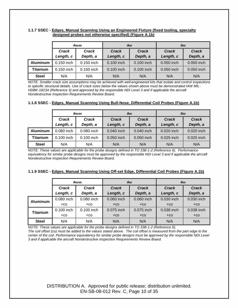
1.1.7 SSEC - Edges, Manual Scanning Using an Engineered Fixture (fixed tooling, specialty designed probes not otherwise specified) (Figure A.1b)
a90/95 a90 a50
Crack Length, c
Crack Depth, a
Crack Length, c
Crack Depth, a
Crack Length, c
Crack Depth, a
Aluminum 0.150 inch 0.150 inch 0.100 inch 0.100 inch 0.050 inch 0.050 inch
Titanium 0.150 inch 0.150 inch 0.100 inch 0.100 inch 0.050 inch 0.050 inch
Steel N/A N/A N/A N/A N/A N/A NOTE: Smaller crack size assumptions may be achieved with well-engineered kits that isolate and control inspections to specific structural details. Use of crack sizes below the values shown above must be demonstrated IAW MIL-HDBK-1823A (Reference 3) and approved by the responsible NDI Level 3 and if applicable the aircraft Nondestructive Inspection Requirements Review Board. 1.1.8 SSEC - Edges, Manual Scanning Using Bull-Nose, Differential Coil Probes (Figure A.1b)
a90/95 a90 a50
Crack Length, c
Crack Depth, a
Crack Length, c
Crack Depth, a
Crack Length, c
Crack Depth, a
Aluminum 0.080 inch 0.080 inch 0.040 inch 0.040 inch 0.020 inch 0.020 inch
Titanium 0.100 inch 0.100 inch 0.050 inch 0.050 inch 0.025 inch 0.025 inch
Steel N/A N/A N/A N/A N/A N/A NOTE: These values are applicable for the probe designs defined in TO 33B-1-2 (Reference 6). Performance equivalency for similar probe designs must be approved by the responsible NDI Level 3 and if applicable the aircraft Nondestructive Inspection Requirements Review Board.
1.1.9 SSEC - Edges, Manual Scanning Using Off-set Edge, Differential Coil Probes (Figure A.1b)
a90/95 a90 a50 Crack
Length, c Crack
Depth, a Crack
Length, c Crack
Depth, a Crack
Length, c Crack
Depth, a
Aluminum 0.080 inch +co
0.080 inch +co
0.060 inch +co
0.060 inch +co
0.030 inch +co
0.030 inch +co
Titanium 0.100 inch +co
0.100 inch +co
0.075 inch +co
0.075 inch +co
0.038 inch +co
0.038 inch +co
Steel N/A N/A N/A N/A N/A N/A NOTE: These values are applicable for the probe designs defined in TO 33B-1-2 (Reference 6). The coil offset (co) must be added to the values stated above. The coil offset is measured from the part edge to the center of the coil. Performance equivalency for similar probe designs must be approved by the responsible NDI Level 3 and if applicable the aircraft Nondestructive Inspection Requirements Review Board.

DISTRIBUTION A. Approved for public release; distribution unlimited.
EN-SB-08-012 Rev. C, Page 11 of 35
1.1.10 SSEC - Manual Scanning, Pencil Probes, Around Raised Fastener Heads – Using Fastener Head as a Guide (Figure A.2c)
a90/95 a90 a50
Crack Length, c
Crack Depth, a
Crack Length, c
Crack Depth, a
Crack Length, c
Crack Depth, a
Aluminum 0.200 inch + fho t 0.150 inch
+ fho t 0.075 inch + fho t
Titanium 0.200 inch + fho t 0.150 inch
+ fho t 0.075 inch + fho t
Steel N/A N/A N/A N/A N/A N/A NOTES: 1) The fastener head overlap (fho) must be added to the values stated above. 2) The above values are independent of fastener alloy provided shielded probes are used. 3) Crack depth shall be assumed to extend through the layer thickness (t) unless it can be verified cracks initiate at inspection surface and propagate with a predictable aspect ratio.
1.1.11 SSEC - Manual Scanning, Pencil Probes, Around Flush Head Fasteners Using a Circle Template as a Guide (Figure A.2d)
a90/95 a90 a50
Crack Length, c
Crack Depth, a
Crack Length, c
Crack Depth, a
Crack Length, c
Crack Depth, a
Aluminum 0.200 inch + fho t 0.150 inch
+ fho t 0.075 inch + fho t
Titanium 0.200 inch + fho t 0.150 inch
+ fho t 0.075 inch + fho t
Steel N/A N/A N/A N/A N/A N/A NOTES: 1) The fastener head overlap (fho) must be added to the values stated above. 2) The above values are independent of fastener alloy provided shielded probes are used. 3) Crack depth shall be assumed to extend through the layer thickness (t) unless it can be verified cracks initiate at inspection surface and propagate with a predictable aspect ratio.

DISTRIBUTION A. Approved for public release; distribution unlimited.
EN-SB-08-012 Rev. C, Page 12 of 35
1.1.12 SSEC – Semi-Automated Scanning Using ECS-3s Surface Scanner and EVi unit.
Scanning across flush head fasteners (Figure A.2d)
a90/95 a90 a50
Substrate Fastener Crack
Length, c Crack
Depth, a Crack
Length, c Crack
Depth, a Crack
Length, c Crack
Depth, a
Aluminum Aluminum 0.080 inch + fho t 0.055 inch
+ fho t 0.030 inch + fho t
Aluminum Titanium 0.080 inch + fho t 0.055 inch
+ fho t 0.030 inch + fho t
Aluminum Steel 0.080 inch + fho t 0.055 inch
+ fho t 0.030 inch + fho t
NOTES: 1) The fastener head overlap (fho) must be added to the values stated above. 2) Crack depth shall be assumed to extend through the layer thickness (t) unless it can be verified cracks initiate at inspection surface and propagate with a predictable aspect ratio.
1.1.13 SSEC - Manual Scanning Around Fastener Heads (Raised and Flush Head) – Using an
Engineered Fixture (fixed tooling, specialty designed probes) (Figure A.2c/d)
a90/95 a90 a50 Crack
Length, c Crack
Depth, a Crack
Length, c Crack
Depth, a Crack
Length, c Crack
Depth, a
Aluminum 0.150 inch + fho t 0.100 inch
+ fho t 0.075 inch + fho t
Titanium 0.150 inch + fho t 0.100 inch
+ fho t 0.075 inch + fho t
Steel N/A N/A N/A N/A N/A N/A NOTES: 1) The fastener head overlap (fho) must be added to the values stated above. 2) Smaller crack size assumptions may be achieved with well-engineered kits that isolate and control inspections to specific structural details. Use of crack sizes above the values shown above must be demonstrated IAW MIL-HDBK-1823A (Reference 3) and approved by the responsible NDI Level 3 and if applicable the aircraft Nondestructive Inspection Requirements Review Board. 3) The above values are independent of fastener alloy provided shielded probes are used. 4) Crack depth shall be assumed to extend through the layer thickness (t) unless it can be verified cracks initiate at inspection surface and propagate with a predictable aspect ratio.

DISTRIBUTION A. Approved for public release; distribution unlimited.
EN-SB-08-012 Rev. C, Page 13 of 35
1.1.14 SSEC - Rotary Raised Head Fastener Scanning, with Differential Coils (Figure A.2.c)
a90/95 a90 a50 Crack
Length, c Crack
Depth, a Crack
Length, c Crack
Depth, a Crack
Length, c Crack
Depth, a
Aluminum 0.100 inch + fho t 0.080 inch
+ fho t 0.040 inch + fho t
Titanium 0.100 inch + fho t 0.080 inch
+ fho t 0.040 inch + fho t
Steel N/A N/A N/A N/A N/A N/A NOTES: 1) The fastener head overlap (fho) must be added to the values stated above. 2) The above values are independent of fastener alloy. 3) These values are applicable for a high speed rotary scanner and probe designs defined in T.O.33B-1-2 (Reference 6). Performance equivalency for similar probe designs must be approved by the responsible NDI Level 3 and if applicable the aircraft Nondestructive Inspection Requirements Review Board. 4) Crack depth shall be assumed to extend through the layer thickness (t) unless it can be verified cracks initiate at inspection surface and propagate with a predictable aspect ratio. 1.1.15 SSEC – Open Hole, Edge Rotary Scanning, with Open Hole Rotary Probes,
with >0.004 inch - ≤ 0.010 inch nonconductive coatings, (Figure A.4)
a90/95 a90 a50 Crack
Length, c Crack
Depth, a * Crack
Length, c Crack
Depth, a * Crack
Length, c Crack
Depth, a * Aluminum 0.065 inch t 0.060 inch t 0.045 inch t
Titanium N/A N/A N/A N/A N/A N/A
Steel N/A N/A N/A N/A N/A N/A NOTES: 1) The depth value is the thickness of the component if the thickness is less than the value noted. 2) These values apply only to high speed rotary scanner applications. 3) Crack depth shall be assumed to extend through the layer thickness (t) unless it can be verified cracks initiate at inspection surface and propagate with a predictable aspect ratio. 1.1.16 SSEC – Open Hole, Edge Rotary Scanning, with Open Hole Rotary Probes, with ≤ 0.004 inch
nonconductive coatings (i.e. no coating or primer only), (Figure A.4)
a90/95 a90 a50 Crack
Length, c Crack
Depth, a * Crack
Length, c Crack
Depth, a Crack
Length, c Crack
Depth, a Aluminum 0.050 inch t 0.045 inch t 0.035 inch t
Titanium 0.050 inch t 0.045 inch t 0.035 inch t
Steel N/A N/A N/A N/A N/A N/A NOTES: 1) The depth value is the thickness of the component if the thickness is less than the value noted. 2) These values apply only to high speed rotary scanner applications. 3) Crack depth shall be assumed to extend through the layer thickness (t) unless it can be verified cracks initiate at inspection surface and propagate with a predictable aspect ratio
DISTRIBUTION A. Approved for public release; distribution unlimited.
EN-SB-08-012 Rev. C, Page 14 of 35
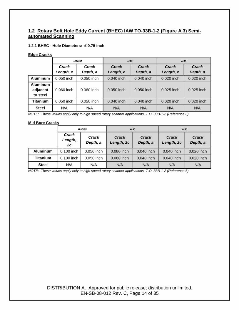
1.2 Rotary Bolt Hole Eddy Current (BHEC) IAW TO-33B-1-2 (Figure A.3) Semi-automated Scanning
1.2.1 BHEC - Hole Diameters: ≤ 0.75 inch
Edge Cracks
a90/95 a90 a50 Crack
Length, c Crack
Depth, a Crack
Length, c Crack
Depth, a Crack
Length, c Crack
Depth, a Aluminum 0.050 inch 0.050 inch 0.040 inch 0.040 inch 0.020 inch 0.020 inch Aluminum adjacent to steel
0.060 inch 0.060 inch 0.050 inch 0.050 inch 0.025 inch 0.025 inch
Titanium 0.050 inch 0.050 inch 0.040 inch 0.040 inch 0.020 inch 0.020 inch
Steel N/A N/A N/A N/A N/A N/A NOTE: These values apply only to high speed rotary scanner applications, T.O. 33B-1-2 (Reference 6) Mid Bore Cracks
a90/95 a90 a50 Crack
Length, 2c
Crack Depth, a
Crack Length, 2c
Crack Depth, a
Crack Length, 2c
Crack Depth, a
Aluminum 0.100 inch 0.050 inch 0.080 inch 0.040 inch 0.040 inch 0.020 inch
Titanium 0.100 inch 0.050 inch 0.080 inch 0.040 inch 0.040 inch 0.020 inch
Steel N/A N/A N/A N/A N/A N/A NOTE: These values apply only to high speed rotary scanner applications, T.O. 33B-1-2 (Reference 6)

DISTRIBUTION A. Approved for public release; distribution unlimited.
EN-SB-08-012 Rev. C, Page 15 of 35
1.2.2 BHEC - Hole Diameters: > 0.75 inch ≤ 2.50 inch Edge Cracks
a90/95 a90 a50 Crack
Length, c Crack
Depth, a Crack
Length, c Crack
Depth, a Crack
Length, c Crack
Depth, a Aluminum 0.060 inch 0.060 inch 0.050 inch 0.050 inch 0.030 inch 0.030 inch Aluminum adjacent to steel
0.070 inch 0.070 inch 0.060 inch 0.060 inch 0.035 inch 0.035 inch
Titanium 0.060 inch 0.060 inch 0.050 inch 0.050 inch 0.030 inch 0.030 inch
Steel N/A N/A N/A N/A N/A N/A NOTE: These values apply only to high speed rotary scanner applications using tailored BHEC probes and filter settings IAW T.O. 33B-1-2 (Reference 6) Mid Bore Cracks
a90/95 a90 a50
Crack Length,
2c
Crack Depth, a
Crack Length, 2c
Crack Depth, a
Crack Length, 2c
Crack Depth, a
Aluminum 0.120 inch 0.120 inch 0.100 inch 0.100 inch 0.060 inch 0.030 inch
Titanium 0.120 inch 0.120 inch 0.100 inch 0.100 inch 0.060 inch 0.030 inch
Steel N/A N/A N/A N/A N/A N/A NOTE: These values apply only to high speed rotary scanner applications using tailored BHEC probes and filter settings IAW T.O. 33B-1-2, Reference 6.

DISTRIBUTION A. Approved for public release; distribution unlimited.
EN-SB-08-012 Rev. C, Page 16 of 35
1.3 ECS-5 Rotary Scanner and EVi Instrument Automated BHEC Scanning - (Figure A.3) – Hole Diameters ≤ 0.75 inch.
Edge Cracks
a90/95 a90 a50 Crack
Length, c Crack
Depth, a Crack
Length, c Crack
Depth, a Crack
Length, c Crack
Depth, a Aluminum 0.050 inch 0.050 inch 0.040 inch 0.040 inch 0.020 inch 0.020 inch Aluminum Adjacent to
steel 0.060 inch 0.060 inch 0.050 inch 0.050 inch 0.025 inch 0.025 inch
Titanium 0.050 inch 0.050 inch 0.040 inch 0.040 inch 0.020 inch 0.020 inch
PH Steels* 0.060 inch 0.060 inch 0.050 inch 0.050 inch 0.030 inch 0.030 inch *NOTE: Applies to precipitation hardened (PH) steels heat treated to greater than 1050H condition.
Mid Bore Cracks
a90/95 a90 a50
Crack Length,
2c
Crack Depth, a
Crack Length, 2c
Crack Depth, a
Crack Length, 2c
Crack Depth, a
Aluminum 0.100 inch 0.050 inch 0.080 inch 0.040 inch 0.040 inch 0.020 inch
Titanium 0.100 inch 0.050 inch 0.080 inch 0.040 inch 0.040 inch 0.020 inch
PH Steels* 0.120 inch 0.120 inch 0.090 inch 0.090 inch 0.045 inch 0.023 inch *NOTE: Applies to precipitation hardened (PH) steels heat treated to greater than 1050H condition.

DISTRIBUTION A. Approved for public release; distribution unlimited.
EN-SB-08-012 Rev. C, Page 17 of 35
2.0 Fluorescent Penetrant Inspection (FPI) Baseline Requirements The penetrant inspection capability values shown in Sections 2.1 and 2.2 are dependent on the following:
1) All fluorescent penetrant inspections require all coatings to be removed. If any form
of abrasive removal process is used, a pre-penetrant etch process per approved technical data shall be accomplished prior to the inspection.
2) Fluorescent penetrant inspection is negatively impacted by compressive residual
stresses and residual stress treatments. FPI is not considered effective on surfaces where deep residual stress treatments such as laser shock peening (LSP) or low plasticity burnishing (LPB) have been applied. Alternate inspection methods such as eddy current should be considered for such applications.
3) Inspection is performed using a Type 1 (Fluorescent), Method C (Solvent Wipe) or
Method D (hydrophilic emulsified) process in accordance with TO 33B-1-2. Form d (nonaqueous) developer shall be used for focused inspections when the values of section 2.1.1 and 2.2.1 are applied. Form d (nonaqueous) or form b (water soluble) developers shall be used when the values of sections 2.1.2 and 2.2.2 are applied.
4) All penetrant materials are qualified in accordance with SAE AMS 2644.
5) All areas of inspection are completely accessible both visually and physically. Visual access is defined as: Inspection location, suspect crack location and assumed crack direction can be identified without the use of visual aids such as a mirror or borescope and direct line of site can be achieved (see view angle requirements below). Physical access is defined as: Inspection location must accommodate the inspector, allow for unencumbered application of penetrant materials, and the ability to view the inspection surface during the dwell and inspection processes.
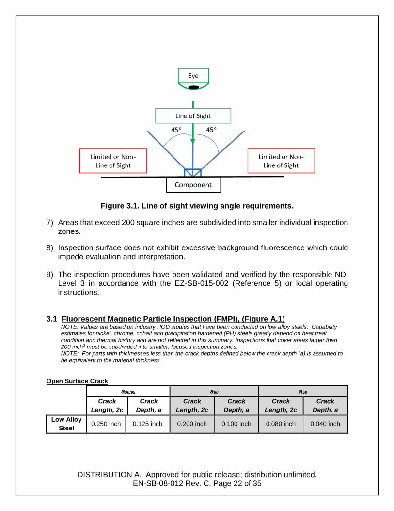
6) View angle – The inspector’s viewing angle must meet the following criteria:
a. The inspection surface must be viewed with both eyes of the inspector, with no interference from required inspection apparatus (e.g. ultraviolet (UV-A) or white light sources), without the use of mirrors or inspection aids.
b. The inspector’s viewing angle must be within 45 degrees of perpendicular to the surface to be inspected (Figure 2.1).
c. The UV light must illuminate the inspection surface being viewed (simultaneously) with the required intensity.
d. The depth to opening ratio for a given location must not be greater than 1.

DISTRIBUTION A. Approved for public release; distribution unlimited.
EN-SB-08-012 Rev. C, Page 18 of 35
Figure 2.1. Line of site (LOS) viewing angle requirements.
7) Areas that exceed 200 square inches are subdivided into smaller individual inspection
zones.
8) Bearings, bushings and other similarly installed hardware that can entrap penetrant are removed prior to penetrant inspections.
9) Inspection surface does not exhibit excessive background fluorescence which could impede evaluation and interpretation.
10) The inspection procedures have been validated and verified by the responsible NDI
Level 3 in accordance with the EZ-SB-15-002 (Reference 5) or local operating instructions.

DISTRIBUTION A. Approved for public release; distribution unlimited.
EN-SB-08-012 Rev. C, Page 19 of 35
2.1 Fluorescent Penetrant Inspection (FPI), Level 4 Sensitivity (Figure A.1) NOTE: For parts with thicknesses less than the crack depths defined below the crack depth (a) is assumed to be equivalent to the material thickness.
2.1.1 FPI - Level 4 Sensitivity, Focused Inspection: < 36 inch2 Open Surface Crack
a90/95 a90 a50 Crack
Length, 2c Crack
Depth, a Crack
Length, 2c Crack
Depth, a Crack
Length, 2c Crack
Depth, a Aluminum 0.100 inch 0.050 inch 0.090 inch 0.045 inch 0.040 inch 0.020 inch
Titanium 0.100 inch 0.050 inch 0.090 inch 0.045 inch 0.040 inch 0.020 inch
Steel 0.100 inch 0.050 inch 0.090 inch 0.045 inch 0.040 inch 0.020 inch Edge Crack
a90/95 a90 a50 Crack
Length, c Crack
Depth, a Crack
Length, c Crack
Depth, a Crack
Length, c Crack
Depth, a Aluminum 0.100 inch 0.100 inch 0.090 inch 0.090 inch 0.040 inch 0.040 inch
Titanium 0.100 inch 0.100 inch 0.090 inch 0.090 inch 0.040 inch 0.040 inch
Steel 0.100 inch 0.100 inch 0.090 inch 0.090 inch 0.040 inch 0.040 inch
2.1.2 FPI - Level 4 Sensitivity, Large Area Inspection: 36 inch2 - 200 inch2
NOTE: Large area inspection values are based on POD studies that have been conducted on individual coupons with areas generally smaller than 36 inch2. Inspections that cover areas larger than 200 inch2 must be subdivided into smaller, focused inspection zones to meet the focused inspection requirements above.
Open Surface Crack
a90/95 a90 a50 Crack
Length, 2c
Crack Depth, a
Crack Length, 2c
Crack Depth, a
Crack Length, 2c
Crack Depth, a
Aluminum 0.200 inch 0.100 inch 0.150 inch 0.075 inch 0.080 inch 0.040 inch
Titanium 0.200 inch 0.100 inch 0.150 inch 0.075 inch 0.080 inch 0.040 inch
Steel 0.200 inch 0.100 inch 0.150 inch 0.075 inch 0.080 inch 0.040 inch
Edge Crack a90/95 a90 a50
Crack Length, c
Crack Depth, a
Crack Length, c
Crack Depth, a
Crack Length, c
Crack Depth, a
Aluminum 0.200 inch 0.200 inch 0.150 inch 0.150 inch 0.080 inch 0.080 inch
Titanium 0.200 inch 0.200 inch 0.150 inch 0.150 inch 0.080 inch 0.080 inch
Steel 0.200 inch 0.200 inch 0.150 inch 0.150 inch 0.080 inch 0.080 inch

DISTRIBUTION A. Approved for public release; distribution unlimited.
EN-SB-08-012 Rev. C, Page 20 of 35
2.2 Fluorescent Penetrant Inspection (FPI), Level 3 Sensitivity (Figure A.1)
NOTE: For parts with thicknesses less than the crack depths defined below the crack depth (a) is assumed to be equivalent to the material thickness.
2.2.1 FPI - Level 3 Sensitivity, Focused Area Inspection: < 36 inch2
Open Surface Crack
a90/95 a90 a50 Crack
Length, 2c Crack
Depth, a Crack
Length, 2c Crack
Depth, a Crack
Length, 2c Crack
Depth, a Aluminum 0.150 inch 0.075 inch 0.120 inch 0.060 inch 0.060 inch 0.030 inch
Titanium 0.150 inch 0.075 inch 0.120 inch 0.060 inch 0.060 inch 0.030 inch
Steel 0.150 inch 0.075 inch 0.120 inch 0.060 inch 0.060 inch 0.030 inch Edge Crack
a90/95 a90 a50 Crack
Length, c Crack
Depth, a Crack
Length, c Crack
Depth, a Crack
Length, c Crack
Depth, a Aluminum 0.150 inch 0.150 inch 0.120 inch 0.120 inch 0.060 inch 0.060 inch
Titanium 0.150 inch 0.150 inch 0.120 inch 0.120 inch 0.060 inch 0.060 inch
Steel 0.150 inch 0.150 inch 0.120 inch 0.120 inch 0.060 inch 0.060 inch
2.2.2 FPI - Level 3 Sensitivity, Large Area Inspection: 36 inch2 - 200 inch2
NOTE: Large area inspection values are based on POD studies that have been conducted on individual coupons with areas generally smaller than 36 inch2. Inspections that cover areas larger than 200 inch2 must be subdivided into smaller, focused inspection zones to meet the focused inspection requirements above.
Open Surface Crack
a90/95 a90 a50 Crack
Length, 2c Crack
Depth, a Crack
Length, 2c Crack
Depth, a Crack
Length, 2c Crack
Depth, a Aluminum 0.250 inch 0.125 inch 0.200 inch 0.100 inch 0.080 inch 0.040 inch
Titanium 0.250 inch 0.125 inch 0.200 inch 0.100 inch 0.080 inch 0.040 inch
Steel 0.250 inch 0.125 inch 0.200 inch 0.100 inch 0.080 inch 0.040 inch Edge Crack
a90/95 a90 a50 Crack
Length, c Crack
Depth, a Crack
Length, c Crack
Depth, a Crack
Length, c Crack
Depth, a Aluminum 0.250 inch 0.250 inch 0.200 inch 0.200 inch 0.080 inch 0.080 inch
Titanium 0.250 inch 0.250 inch 0.200 inch 0.200 inch 0.080 inch 0.080 inch
Steel 0.250 inch 0.250 inch 0.200 inch 0.200 inch 0.080 inch 0.080 inch

DISTRIBUTION A. Approved for public release; distribution unlimited.
EN-SB-08-012 Rev. C, Page 21 of 35
3.0 Fluorescent Magnetic Particle Inspection (FMPI) Baseline Requirements The fluorescent magnetic particle capability values shown in Sections 3.1 and 3.2 are dependent on the following:
1) Values apply to use of bench inspections only using mixed suspensions and
alternating current magnetization. These values do not apply to use of aerosol suspensions or portable inspections using yokes (Reference 30).
2) Values apply to low alloy, ferromagnetic steels only (4XXX, 300M, etc.).
3) To achieve the stated capability values all coatings and plating must be removed before inspection.
4) All FMPI materials meet the requirements of SAE AMS 3044 and SAE AMS 2641.
5) All areas of inspection are completely accessible both visually and physically. Visual
access is defined as: Inspection location, suspect crack location and assumed crack direction can be identified without the use of visual aids such as a mirror or borescope and direct line of site can be achieved (see view angle requirements below). Physical access is defined as: Inspection location must accommodate the inspector, allow for unencumbered application of penetrant materials, and the ability to view the inspection surface during the dwell and inspection processes.
6) View angle – direct line of site. The inspector’s viewing angle must meet the following
criteria:
a. The inspection surface must be viewed with both eyes of the inspector, with no interference from required inspection apparatus (e.g. ultraviolet (UV-A) or white light sources), without the use of mirrors or inspection aids.
b. The inspector’s viewing angle must be within 45 degrees of perpendicular to the surface to be inspected (Figure 3.1).
c. The UV light must illuminate the inspection surface being viewed (simultaneously) with the required intensity.
d. The depth to opening ratio for a given location must not be greater than 1.
DISTRIBUTION A. Approved for public release; distribution unlimited.
EN-SB-08-012 Rev. C, Page 22 of 35
Figure 3.1. Line of sight viewing angle requirements.
7) Areas that exceed 200 square inches are subdivided into smaller individual inspection zones.
8) Inspection surface does not exhibit excessive background fluorescence which could
impede evaluation and interpretation.
9) The inspection procedures have been validated and verified by the responsible NDI Level 3 in accordance with the EZ-SB-015-002 (Reference 5) or local operating instructions.
3.1 Fluorescent Magnetic Particle Inspection (FMPI), (Figure A.1) NOTE: Values are based on industry POD studies that have been conducted on low alloy steels. Capability estimates for nickel, chrome, cobalt and precipitation hardened (PH) steels greatly depend on heat treat condition and thermal history and are not reflected in this summary. Inspections that cover areas larger than 200 inch2 must be subdivided into smaller, focused inspection zones. NOTE: For parts with thicknesses less than the crack depths defined below the crack depth (a) is assumed to be equivalent to the material thickness.
Open Surface Crack
a90/95 a90 a50 Crack
Length, 2c Crack
Depth, a Crack
Length, 2c Crack
Depth, a Crack
Length, 2c Crack
Depth, a Low Alloy
Steel 0.250 inch 0.125 inch 0.200 inch 0.100 inch 0.080 inch 0.040 inch

DISTRIBUTION A. Approved for public release; distribution unlimited.
EN-SB-08-012 Rev. C, Page 23 of 35
Edge Crack a90/95 a90 a50
Crack Length, c
Crack Depth, a
Crack Length, c
Crack Depth, a
Crack Length, c
Crack Depth, a
Low Alloy Steel 0.250 inch 0.250 inch 0.200 inch 0.200 inch 0.080 inch 0.080 inch
4.0 Ultrasonic Inspection (UT) Ultrasonic NDI capabilities are unique to each specific location (geometry and material). The specific NDI capabilities for each control point must be established on a case-by-case basis and consider the following: 1) Inspection capability is based on the part/geometry, structural complexity, ease of
inspection and signal interpretation (including signal-to-noise ratio).
2) Inspection procedures clearly detail (both in text and graphics) the inspection location, inspection zone, crack orientation and scan requirements.
3) Surfaces to be inspected must be smooth and free of flaking and/or non-uniform coatings. If inspecting primary structure (such as skins, stringers, longerons, etc.), all low observable (LO) coatings will be removed.
4) Ultrasonic inspection procedures shall be validated and verified by the responsible NDI Level 3 in accordance with EZ-SB-015-002 (Reference 5) or local operating instructions.
5) Internal condition of the material to be inspected should be free of inconsistent grain
structure or coarse grain structures. Coarse grain alloys will result in significant ultrasound scattering and attenuation often preventing effective inspection particularly for shear-wave techniques. Refracted longitudinal wave techniques are impacted to a lesser degree.
6) Ultrasonic inspection capability is significantly impacted by compressive stress fields
resulting from internal residual stresses, assembly stresses and ground loads. Assume a minimum signal amplitude debit of 3dB per 2ksi of compressive stress when developing procedures and estimating detection capability.
7) Ultrasonic inspection is not effective for detection of fatigue cracks initiating from
surface with deep residual compressive stress treatments such as laser shock peening, low plasticity burnishing, etc. Eddy current inspection should be considered for such applications.
8) Ultrasonic inspection capability of cold worked holes is significantly impacted by the
compressive stress field imparted by the cold working process. The cold working

DISTRIBUTION A. Approved for public release; distribution unlimited.
EN-SB-08-012 Rev. C, Page 24 of 35
results in an “ultrasonic dead zone” where the crack surfaces are compressed together enabling the ultrasonic energy to pass through the crack without a detectable reflection. The ultrasonic dead zone may extend up to one hole radius into the substrate as measured from the hole edge. This dead zone must be accounted for in capability estimates. The “dead-zone” for a 4% cold expanded hole can be estimated as a function of the hole diameter as follows:
Dead Zone (inches) = 0.3219 x Hole Diameter - 0.038
5.0 Visual Inspection The capability of visual inspections, to include borescopes, has not been formally evaluated. Visual inspections are typically performed by non-NDI personnel with no visual inspection specific training, and are routinely performed in addition to NDI or when no other reliable NDI options are available. Although visual inspection is not recognized as an NDI method by the USAF, it is an extremely useful tool to identify structural damage. Any use of visual inspection methods should consider the following: 1) Visual inspection requirements published in NDI technical manuals must be
documented, validated, verified, and approved by the NDI Level 3 similarly to NDI methods.
2) Visual inspections shall NOT be used as the primary inspection method for NDI of
safety-of-flight structures whose NDI requirement is based upon a slow crack growth damage tolerant design.
3) It is acceptable to use visual inspection to detect failed (i.e. severed) safety-of-flight
structures that incorporate a fail-safe damage tolerant design.
4) It is acceptable to use visual inspection on structures, including safety-of-flight structures, as an over-and-above requirement to a damage tolerance based inspection.
5) It is acceptable to use visual inspection to identify foreign object debris or damage (FOD) and gross system damage from overloads, hard landings, etc.
6) In all cases, the capability of visual inspection shall be assumed at > 2.0 inches or a
severed component if the component is less than 2.0 inches.

DISTRIBUTION A. Approved for public release; distribution unlimited.
EN-SB-08-012 Rev. C, Page 25 of 35
6.0 Magneto Optical Imaging (MOI) Requirements The MOI capability values shown in Section 6.1 are dependent on the following: 1) The MOI 306, MOI 308/7, MOI+, or equivalent instrument is used with rotating eddy
current field. The sensor area shall be no larger than 1.8 inch x 1.8 inch. Equivalency must be determined by the responsible NDI Level 3.
2) Inspection area must be sufficiently flat to maintain direct contact of the entire sensor
to the inspection surface. 3) The POD values established herein are based on an inspection frequency of 150 kHz
and Mid/High excitation level. The responsible NDI Level 3 must verify the performance and capability of procedures that deviate from these parameters.
4) The temperature of the inspection surface must be between 32°F to 104°F. The
sensitivity of the MOI inspection will be degraded outside of this range. 5) Ferromagnetic fasteners shall be degaussed prior to inspection. 6) Inspection areas are completely accessible both visually and physically. Visual
access is defined as: Inspection location, suspect crack location and assumed crack direction can be identified without the use of visual aids such as a mirror or borescope. Physical access is defined as: Inspection location must accommodate the inspector and the MOI sensor, allow for unencumbered manipulation of the sensor, and the ability to monitor the MOI image while scanning the component.
7) Inspections are performed on a single row of fasteners at a time unless otherwise
approved by NDI Level 3. 8) The scan speed is limited to not more than 2 inches per second. Inspectors should
be provided a ten minute break with every 30 minutes of continuous scanning. 9) Procedures must clearly define all set-up and system performance check
parameters. Recurring performance checks on representative specimens with known cracks must be performed.
10) Lift-off as a result of non-conductive coatings shall be no greater than 0.010 inch (10
mils) thick. 11) Sufficient guidance for image interpretation is provided within the inspection
procedure. 12) Part specific procedures clearly detail (both in text and graphics) the inspection
location, inspection zone, the crack orientation and scan requirements.

DISTRIBUTION A. Approved for public release; distribution unlimited.
EN-SB-08-012 Rev. C, Page 26 of 35
13) The inspection procedures have been validated and verified by the responsible NDI Level 3 in accordance with the EZ-SB-015-002 (Reference 5) or local operating instructions.
14) Procedures and training should address interpretation of connected indications
(fastener-to-fastener and fastener-to-edge cracks). 6.1 Magneto Optical Imaging (Figure A.2c)
a90/95 a90 a50
Substrate Fastener Crack
Length, c Crack
Depth, a Crack
Length, c Crack
Depth, a Crack
Length, c Crack
Depth, a
Aluminum Aluminum 0.200 inch
+ fho t 0.120 inch + fho t 0.060 inch
+ fho t
Aluminum Titanium 0.200 inch
+ fho t 0.120 inch + fho t 0.060 inch
+ fho t
Aluminum Steel 0.200 inch
+ fho t 0.120 inch + fho t 0.060 inch
+ fho t
NOTES: 1) The fastener head overlap (fho) must be added to the values stated above. 2) For parts with thickness less than the crack depths defined above the crack depth (a) is assumed to be equivalent to the material thickness. 3) Crack depth shall be assumed to extend through the layer thickness (t) unless it can be verified cracks initiate at inspection surface and propagate with a predictable aspect ratio.

DISTRIBUTION A. Approved for public release; distribution unlimited.
EN-SB-08-012 Rev. C, Page 27 of 35
7.0 Radiography (RT) Requirements The film and computed radiography (CR) crack detection capability estimates are dependent on the following: 1) Procedures must use an approved film and/or CR inspection system.
a. Approved film systems shall comply with T.O. 33B-1-1 (i.e. Class II film: Agfa D4, Kodak Type M, and Fuji IX 50).
b. Approved CR systems are listed in T.O. 33B-1-2 WP 106 01 Table 4, along with imaging plate type, sampling resolution, and other equipment settings.
2) Part specific procedures must clearly detail (both in text and graphics) the inspection
location, inspection zone, the crack orientation, and technique.
3) The inspection procedures have been validated and verified by the responsible NDI Level 3 in accordance with EZ-SB-15-002 (Reference 5) or local operating instructions.
4) CR procedures must be developed using the CR Crack Detection Procedure
Development Process as documented in “Computed Radiography Technique Development Procedures for USAF Airframe Crack Detection Applications” (Reference 28). An update to Reference 28 will be included in a future revision of T.O.33B-1-1.
5) POD values are presented based on the ratio of the cracked layer thickness to the
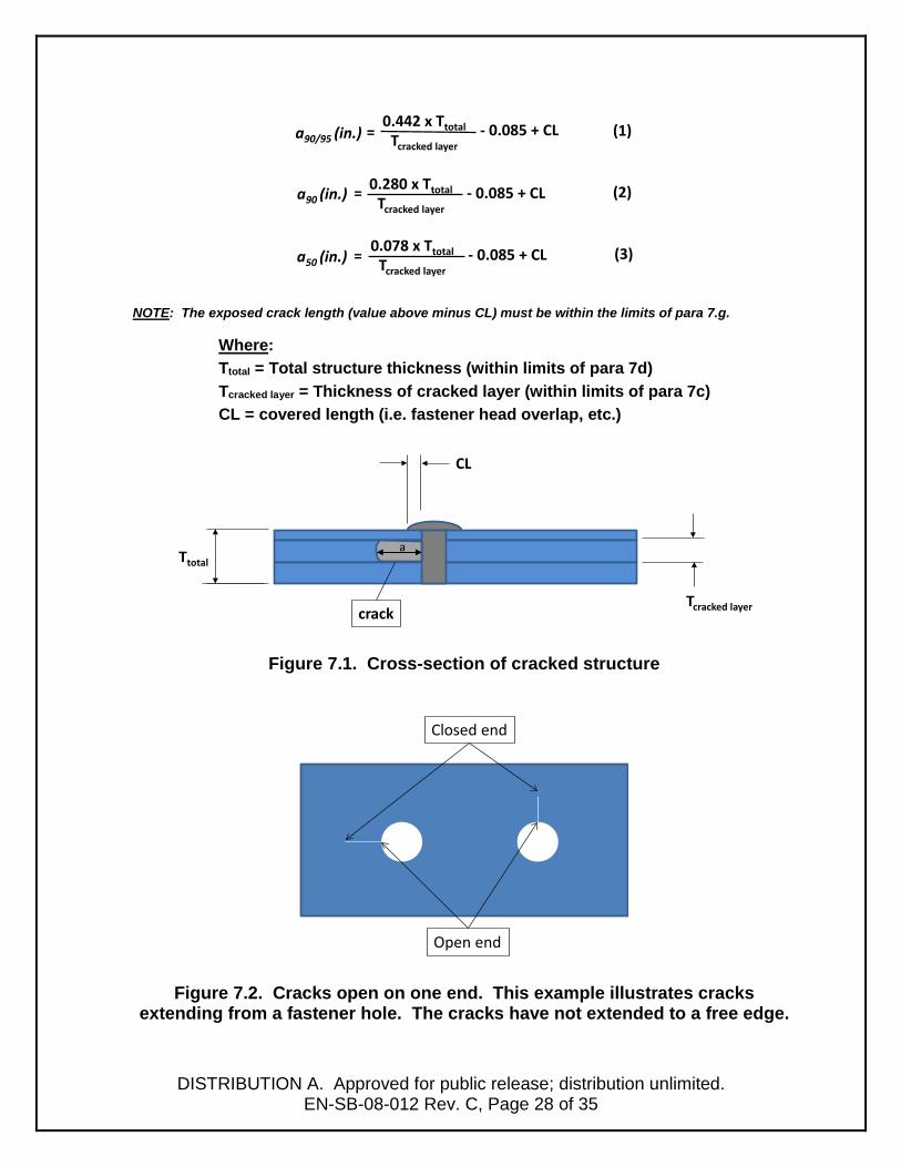
total section thickness, to include all layers between the source and imaging media (film or imaging plate). Formulas 1 through 3 calculate POD crack lengths for a90/95, a90, and a50 respectively, with Figure 7.1 illustrating the formula parameters. Table 7.1 and Figure 7.2 are provided for clarity, illustrating the limits of the formulas. Tables 7.2 through 7.4 provide the same data, but in a simple lookup table.
6) The POD values were established for a limited range of applications (Reference 29): a. Aluminum airframe fatigue cracks grown from a fastener hole (i.e. crack open
on one end only, see Figure 7.2) b. Through thickness cracks (in the cracked layer) c. Crack layer thickness from 0.040 inch to 0.375 inch d. Total cross-section thickness from 0.375 inch to 1.125 inch e. All layers are aluminum. f. The CR POD estimates were developed without use of post-processing filters
on the CR images. g. Exposed crack lengths ranged from 0.137 to 1.100 inch. h. Lengths of cracks extending from opposite sides of a hole cannot be
summed. Each crack must be treated independently.
DISTRIBUTION A. Approved for public release; distribution unlimited.
EN-SB-08-012 Rev. C, Page 28 of 35
NOTE: The exposed crack length (value above minus CL) must be within the limits of para 7.g.
Where: Ttotal = Total structure thickness (within limits of para 7d) Tcracked layer = Thickness of cracked layer (within limits of para 7c) CL = covered length (i.e. fastener head overlap, etc.)
Figure 7.1. Cross-section of cracked structure
Figure 7.2. Cracks open on one end. This example illustrates cracks extending from a fastener hole. The cracks have not extended to a free edge.
a90/95 (in.) =0.442 x Ttotal - 0.085 + CL
a90 (in.) =
a50 (in.) =
(1)
(3)
(2)
Tcracked layer
0.280 x Ttotal - 0.085 + CLTcracked layer
0.078 x Ttotal - 0.085 + CLTcracked layer
CL
crackTcracked layer
Ttotala
Open end
Closed end

DISTRIBUTION A. Approved for public release; distribution unlimited.
EN-SB-08-012 Rev. C, Page 29 of 35
Table 7.1. Radiography (Film and CR) Crack Detection Capability Exposed Crack Length (in)*
* NOTE: The covered length (e.g. fastener head overlap, etc.) must be added to the values.
* NOTE: The covered length (e.g. fastener head overlap, etc.) must be added to the values.
Figure 7.3. Radiography (Film and CR) Crack Detection Capability
Exposed Crack Length*
10% 20% 30% 40% 50% 60% 70% 80% 90% 100%
a90/95 4.34 2.13 1.39 1.02 0.80 0.65 0.55 0.47 0.41 0.36
a90 2.72 1.32 0.85 0.62 0.48 0.38 0.32 0.27 0.23 0.20
a50 0.70 0.31 0.18 0.14 0.14 0.14 0.14 0.14 0.14 0.14
probabilitycrack layer as % total section thickness
Radiography not recommended
Radiography not recommended
0.00
0.20
0.40
0.60
0.80
1.00
0% 20% 40% 60% 80% 100%
crac
k le
ngth
(inc
hes)
% of total section thickness
CR Capability for crack length as a function of % of total section thickness (combined stackup POD)
a90/95
a90
a50

DISTRIBUTION A. Approved for public release; distribution unlimited.
EN-SB-08-012 Rev. C, Page 30 of 35
Table 7.2. Radiography (Film and CR) a90/95 Crack Detection Capability Exposed Crack Length*
* NOTE: The covered length (e.g. fastener head overlap, etc.) must be added to the values.
Table 7.3. Radiography (Film and CR) a90 Crack Detection Capability
Exposed Crack Length *
* NOTE: The covered length (e.g. fastener head overlap, etc.) must be added to the values.
a90/95
0.375 0.425 0.475 0.525 0.575 0.625 0.675 0.725 0.775 0.825 0.875 0.925 0.975 1.025 1.075 1.1250.040 4.06 4.61 5.16 5.72 6.27 6.82 7.37 7.93 8.48 9.03 9.58 10.14 10.69 11.24 11.79 12.350.050 3.23 3.67 4.11 4.56 5.00 5.44 5.88 6.32 6.77 7.21 7.65 8.09 8.53 8.98 9.42 9.860.060 2.68 3.05 3.41 3.78 4.15 4.52 4.89 5.26 5.62 5.99 6.36 6.73 7.10 7.47 7.83 8.200.070 2.28 2.60 2.91 3.23 3.55 3.86 4.18 4.49 4.81 5.12 5.44 5.76 6.07 6.39 6.70 7.020.080 1.99 2.26 2.54 2.82 3.09 3.37 3.64 3.92 4.20 4.47 4.75 5.03 5.30 5.58 5.85 6.130.090 1.76 2.00 2.25 2.49 2.74 2.98 3.23 3.48 3.72 3.97 4.21 4.46 4.70 4.95 5.19 5.440.100 1.57 1.79 2.01 2.24 2.46 2.68 2.90 3.12 3.34 3.56 3.78 4.00 4.22 4.45 4.67 4.890.110 1.42 1.62 1.82 2.02 2.23 2.43 2.63 2.83 3.03 3.23 3.43 3.63 3.83 4.03 4.23 4.440.120 1.30 1.48 1.66 1.85 2.03 2.22 2.40 2.59 2.77 2.95 3.14 3.32 3.51 3.69 3.87 4.060.130 1.19 1.36 1.53 1.70 1.87 2.04 2.21 2.38 2.55 2.72 2.89 3.06 3.23 3.40 3.57 3.740.140 1.10 1.26 1.41 1.57 1.73 1.89 2.05 2.20 2.36 2.52 2.68 2.84 2.99 3.15 3.31 3.470.150 1.02 1.17 1.31 1.46 1.61 1.76 1.90 2.05 2.20 2.35 2.49 2.64 2.79 2.94 3.08 3.230.160 0.95 1.09 1.23 1.37 1.50 1.64 1.78 1.92 2.06 2.19 2.33 2.47 2.61 2.75 2.88 3.020.170 0.89 1.02 1.15 1.28 1.41 1.54 1.67 1.80 1.93 2.06 2.19 2.32 2.45 2.58 2.71 2.840.180 0.84 0.96 1.08 1.20 1.33 1.45 1.57 1.70 1.82 1.94 2.06 2.19 2.31 2.43 2.55 2.680.190 0.79 0.90 1.02 1.14 1.25 1.37 1.49 1.60 1.72 1.83 1.95 2.07 2.18 2.30 2.42 2.530.200 0.74 0.85 0.96 1.08 1.19 1.30 1.41 1.52 1.63 1.74 1.85 1.96 2.07 2.18 2.29 2.400.210 0.70 0.81 0.91 1.02 1.13 1.23 1.34 1.44 1.55 1.65 1.76 1.86 1.97 2.07 2.18 2.280.220 0.67 0.77 0.87 0.97 1.07 1.17 1.27 1.37 1.47 1.57 1.67 1.77 1.87 1.97 2.07 2.180.230 0.64 0.73 0.83 0.92 1.02 1.12 1.21 1.31 1.40 1.50 1.60 1.69 1.79 1.88 1.98 2.080.240 0.61 0.70 0.79 0.88 0.97 1.07 1.16 1.25 1.34 1.43 1.53 1.62 1.71 1.80 1.89 1.990.250 0.58 0.67 0.75 0.84 0.93 1.02 1.11 1.20 1.29 1.37 1.46 1.55 1.64 1.73 1.82 1.900.260 0.55 0.64 0.72 0.81 0.89 0.98 1.06 1.15 1.23 1.32 1.40 1.49 1.57 1.66 1.74 1.830.270 0.53 0.61 0.69 0.77 0.86 0.94 1.02 1.10 1.18 1.27 1.35 1.43 1.51 1.59 1.67 1.760.280 0.51 0.59 0.66 0.74 0.82 0.90 0.98 1.06 1.14 1.22 1.30 1.38 1.45 1.53 1.61 1.690.290 0.49 0.56 0.64 0.72 0.79 0.87 0.94 1.02 1.10 1.17 1.25 1.32 1.40 1.48 1.55 1.630.300 0.47 0.54 0.61 0.69 0.76 0.84 0.91 0.98 1.06 1.13 1.20 1.28 1.35 1.43 1.50 1.570.310 0.45 0.52 0.59 0.66 0.73 0.81 0.88 0.95 1.02 1.09 1.16 1.23 1.31 1.38 1.45 1.520.320 0.43 0.50 0.57 0.64 0.71 0.78 0.85 0.92 0.99 1.05 1.12 1.19 1.26 1.33 1.40 1.470.330 0.42 0.48 0.55 0.62 0.69 0.75 0.82 0.89 0.95 1.02 1.09 1.15 1.22 1.29 1.35 1.420.340 0.40 0.47 0.53 0.60 0.66 0.73 0.79 0.86 0.92 0.99 1.05 1.12 1.18 1.25 1.31 1.380.350 0.39 0.45 0.51 0.58 0.64 0.70 0.77 0.83 0.89 0.96 1.02 1.08 1.15 1.21 1.27 1.340.360 0.38 0.44 0.50 0.56 0.62 0.68 0.74 0.81 0.87 0.93 0.99 1.05 1.11 1.17 1.23 1.300.370 0.36 0.42 0.48 0.54 0.60 0.66 0.72 0.78 0.84 0.90 0.96 1.02 1.08 1.14 1.20 1.260.375 0.36 0.42 0.47 0.53 0.59 0.65 0.71 0.77 0.83 0.89 0.95 1.01 1.06 1.12 1.18 1.24
total stackup thickness (in)crack layer thickness (in)
a90
0.375 0.425 0.475 0.525 0.575 0.625 0.675 0.725 0.775 0.825 0.875 0.925 0.975 1.025 1.075 1.1250.040 2.54 2.89 3.24 3.59 3.94 4.29 4.64 4.99 5.34 5.69 6.04 6.39 6.74 7.09 7.44 7.790.050 2.02 2.30 2.58 2.86 3.14 3.42 3.70 3.98 4.26 4.54 4.82 5.10 5.38 5.66 5.94 6.220.060 1.67 1.90 2.13 2.37 2.60 2.83 3.07 3.30 3.53 3.77 4.00 4.23 4.47 4.70 4.93 5.170.070 1.42 1.62 1.82 2.02 2.22 2.42 2.62 2.82 3.02 3.22 3.42 3.62 3.82 4.02 4.22 4.420.080 1.23 1.40 1.58 1.75 1.93 2.10 2.28 2.45 2.63 2.80 2.98 3.15 3.33 3.50 3.68 3.850.090 1.08 1.24 1.39 1.55 1.70 1.86 2.02 2.17 2.33 2.48 2.64 2.79 2.95 3.10 3.26 3.420.100 0.97 1.11 1.25 1.39 1.53 1.67 1.81 1.95 2.09 2.23 2.37 2.51 2.65 2.79 2.93 3.070.110 0.87 1.00 1.12 1.25 1.38 1.51 1.63 1.76 1.89 2.02 2.14 2.27 2.40 2.52 2.65 2.780.120 0.79 0.91 1.02 1.14 1.26 1.37 1.49 1.61 1.72 1.84 1.96 2.07 2.19 2.31 2.42 2.540.130 0.72 0.83 0.94 1.05 1.15 1.26 1.37 1.48 1.58 1.69 1.80 1.91 2.02 2.12 2.23 2.340.140 0.67 0.77 0.87 0.97 1.07 1.17 1.27 1.37 1.47 1.57 1.67 1.77 1.87 1.97 2.07 2.170.150 0.62 0.71 0.80 0.90 0.99 1.08 1.18 1.27 1.36 1.46 1.55 1.64 1.74 1.83 1.92 2.020.160 0.57 0.66 0.75 0.83 0.92 1.01 1.10 1.18 1.27 1.36 1.45 1.53 1.62 1.71 1.80 1.880.170 0.53 0.62 0.70 0.78 0.86 0.94 1.03 1.11 1.19 1.27 1.36 1.44 1.52 1.60 1.69 1.770.180 0.50 0.58 0.65 0.73 0.81 0.89 0.97 1.04 1.12 1.20 1.28 1.35 1.43 1.51 1.59 1.670.190 0.47 0.54 0.62 0.69 0.76 0.84 0.91 0.98 1.06 1.13 1.20 1.28 1.35 1.43 1.50 1.570.200 0.44 0.51 0.58 0.65 0.72 0.79 0.86 0.93 1.00 1.07 1.14 1.21 1.28 1.35 1.42 1.490.210 0.42 0.48 0.55 0.62 0.68 0.75 0.82 0.88 0.95 1.02 1.08 1.15 1.22 1.28 1.35 1.420.220 0.39 0.46 0.52 0.58 0.65 0.71 0.77 0.84 0.90 0.97 1.03 1.09 1.16 1.22 1.28 1.350.230 0.37 0.43 0.49 0.55 0.62 0.68 0.74 0.80 0.86 0.92 0.98 1.04 1.10 1.16 1.22 1.280.240 0.35 0.41 0.47 0.53 0.59 0.64 0.70 0.76 0.82 0.88 0.94 0.99 1.05 1.11 1.17 1.230.250 0.34 0.39 0.45 0.50 0.56 0.62 0.67 0.73 0.78 0.84 0.90 0.95 1.01 1.06 1.12 1.180.260 0.32 0.37 0.43 0.48 0.53 0.59 0.64 0.70 0.75 0.80 0.86 0.91 0.97 1.02 1.07 1.130.270 0.30 0.36 0.41 0.46 0.51 0.56 0.62 0.67 0.72 0.77 0.82 0.87 0.93 0.98 1.03 1.080.280 0.29 0.34 0.39 0.44 0.49 0.54 0.59 0.64 0.69 0.74 0.79 0.84 0.89 0.94 0.99 1.040.290 0.28 0.33 0.37 0.42 0.47 0.52 0.57 0.62 0.66 0.71 0.76 0.81 0.86 0.90 0.95 1.000.300 0.27 0.31 0.36 0.41 0.45 0.50 0.55 0.59 0.64 0.69 0.73 0.78 0.83 0.87 0.92 0.970.310 0.25 0.30 0.34 0.39 0.43 0.48 0.52 0.57 0.62 0.66 0.71 0.75 0.80 0.84 0.89 0.930.320 0.24 0.29 0.33 0.37 0.42 0.46 0.51 0.55 0.59 0.64 0.68 0.72 0.77 0.81 0.86 0.900.330 0.23 0.28 0.32 0.36 0.40 0.45 0.49 0.53 0.57 0.62 0.66 0.70 0.74 0.78 0.83 0.870.340 0.22 0.27 0.31 0.35 0.39 0.43 0.47 0.51 0.55 0.59 0.64 0.68 0.72 0.76 0.80 0.840.350 0.22 0.26 0.30 0.34 0.38 0.42 0.46 0.50 0.54 0.58 0.62 0.66 0.70 0.74 0.78 0.820.360 0.21 0.25 0.28 0.32 0.36 0.40 0.44 0.48 0.52 0.56 0.60 0.63 0.67 0.71 0.75 0.790.370 0.20 0.24 0.27 0.31 0.35 0.39 0.43 0.46 0.50 0.54 0.58 0.62 0.65 0.69 0.73 0.770.375 0.20 0.23 0.27 0.31 0.34 0.38 0.42 0.46 0.49 0.53 0.57 0.61 0.64 0.68 0.72 0.76
crack layer thickness (in)
total stackup thickness (in)

DISTRIBUTION A. Approved for public release; distribution unlimited.
EN-SB-08-012 Rev. C, Page 31 of 35
Table 7.4. Radiography (Film and CR) a50 Crack Detection Capability Exposed Crack Length * **
* NOTE: The covered length (e.g. fastener head overlap, etc.) must be added to the values.
** NOTE: Gray shaded cells are the minimum crack length used in the POD study. 7) The effect of variables that may improve or degrade POD values shall be assessed
by the responsible level 3 and incorporated into the POD estimation. Some variables to consider include:
a. Cracks that grow to a free edge may be wider than cracks that are “closed”, which may improve detection capability.
b. Cracks under compressive loading may have degraded detection capability (e.g. lower wing skin with full fuel loading). Conversely, cracks under tensile loading may have improved detection capability (e.g. lower wing skin with jack loading)
c. Use of CR post processing filters shall be approved by the responsible NDI Level 3 and the indication shall still be visible when filters are removed.
a50
0.375 0.425 0.475 0.525 0.575 0.625 0.675 0.725 0.775 0.825 0.875 0.925 0.975 1.025 1.075 1.1250.040 0.65 0.74 0.84 0.94 1.04 1.13 1.23 1.33 1.43 1.52 1.62 1.72 1.82 1.91 2.01 2.110.050 0.50 0.58 0.66 0.73 0.81 0.89 0.97 1.05 1.12 1.20 1.28 1.36 1.44 1.51 1.59 1.670.060 0.40 0.47 0.53 0.60 0.66 0.73 0.79 0.86 0.92 0.99 1.05 1.12 1.18 1.25 1.31 1.380.070 0.33 0.39 0.44 0.50 0.56 0.61 0.67 0.72 0.78 0.83 0.89 0.95 1.00 1.06 1.11 1.170.080 0.28 0.33 0.38 0.43 0.48 0.52 0.57 0.62 0.67 0.72 0.77 0.82 0.87 0.91 0.96 1.010.090 0.24 0.28 0.33 0.37 0.41 0.46 0.50 0.54 0.59 0.63 0.67 0.72 0.76 0.80 0.85 0.890.100 0.21 0.25 0.29 0.32 0.36 0.40 0.44 0.48 0.52 0.56 0.60 0.64 0.68 0.71 0.75 0.790.110 0.18 0.22 0.25 0.29 0.32 0.36 0.39 0.43 0.46 0.50 0.54 0.57 0.61 0.64 0.68 0.710.120 0.16 0.19 0.22 0.26 0.29 0.32 0.35 0.39 0.42 0.45 0.48 0.52 0.55 0.58 0.61 0.650.130 0.14 0.17 0.20 0.23 0.26 0.29 0.32 0.35 0.38 0.41 0.44 0.47 0.50 0.53 0.56 0.590.140 0.14 0.15 0.18 0.21 0.24 0.26 0.29 0.32 0.35 0.37 0.40 0.43 0.46 0.49 0.51 0.540.150 0.14 0.14 0.16 0.19 0.21 0.24 0.27 0.29 0.32 0.34 0.37 0.40 0.42 0.45 0.47 0.500.160 0.14 0.14 0.15 0.17 0.20 0.22 0.24 0.27 0.29 0.32 0.34 0.37 0.39 0.41 0.44 0.460.170 0.14 0.14 0.14 0.16 0.18 0.20 0.22 0.25 0.27 0.29 0.32 0.34 0.36 0.39 0.41 0.430.180 0.14 0.14 0.14 0.14 0.16 0.19 0.21 0.23 0.25 0.27 0.29 0.32 0.34 0.36 0.38 0.400.190 0.14 0.14 0.14 0.14 0.15 0.17 0.19 0.21 0.23 0.25 0.27 0.29 0.32 0.34 0.36 0.380.200 0.14 0.14 0.14 0.14 0.14 0.16 0.18 0.20 0.22 0.24 0.26 0.28 0.30 0.31 0.33 0.350.210 0.14 0.14 0.14 0.14 0.14 0.15 0.17 0.18 0.20 0.22 0.24 0.26 0.28 0.30 0.31 0.330.220 0.14 0.14 0.14 0.14 0.14 0.14 0.15 0.17 0.19 0.21 0.23 0.24 0.26 0.28 0.30 0.310.230 0.14 0.14 0.14 0.14 0.14 0.14 0.14 0.16 0.18 0.19 0.21 0.23 0.25 0.26 0.28 0.300.240 0.14 0.14 0.14 0.14 0.14 0.14 0.14 0.15 0.17 0.18 0.20 0.22 0.23 0.25 0.26 0.280.250 0.14 0.14 0.14 0.14 0.14 0.14 0.14 0.14 0.16 0.17 0.19 0.20 0.22 0.23 0.25 0.270.260 0.14 0.14 0.14 0.14 0.14 0.14 0.14 0.14 0.15 0.16 0.18 0.19 0.21 0.22 0.24 0.250.270 0.14 0.14 0.14 0.14 0.14 0.14 0.14 0.14 0.14 0.15 0.17 0.18 0.20 0.21 0.23 0.240.280 0.14 0.14 0.14 0.14 0.14 0.14 0.14 0.14 0.14 0.14 0.16 0.17 0.19 0.20 0.21 0.230.290 0.14 0.14 0.14 0.14 0.14 0.14 0.14 0.14 0.14 0.14 0.15 0.16 0.18 0.19 0.20 0.220.300 0.14 0.14 0.14 0.14 0.14 0.14 0.14 0.14 0.14 0.14 0.14 0.16 0.17 0.18 0.19 0.210.310 0.14 0.14 0.14 0.14 0.14 0.14 0.14 0.14 0.14 0.14 0.14 0.15 0.16 0.17 0.19 0.200.320 0.14 0.14 0.14 0.14 0.14 0.14 0.14 0.14 0.14 0.14 0.14 0.14 0.15 0.16 0.18 0.190.330 0.14 0.14 0.14 0.14 0.14 0.14 0.14 0.14 0.14 0.14 0.14 0.14 0.15 0.16 0.17 0.180.340 0.14 0.14 0.14 0.14 0.14 0.14 0.14 0.14 0.14 0.14 0.14 0.14 0.14 0.15 0.16 0.170.350 0.14 0.14 0.14 0.14 0.14 0.14 0.14 0.14 0.14 0.14 0.14 0.14 0.14 0.14 0.15 0.170.360 0.14 0.14 0.14 0.14 0.14 0.14 0.14 0.14 0.14 0.14 0.14 0.14 0.14 0.14 0.15 0.160.370 0.14 0.14 0.14 0.14 0.14 0.14 0.14 0.14 0.14 0.14 0.14 0.14 0.14 0.14 0.14 0.150.375 0.14 0.14 0.14 0.14 0.14 0.14 0.14 0.14 0.14 0.14 0.14 0.14 0.14 0.14 0.14 0.15
crack layer thickness (in)
total stackup thickness (in)

DISTRIBUTION A. Approved for public release; distribution unlimited.
EN-SB-08-012 Rev. C, Page 32 of 35
8.0 NDI Capability Adjustment Factors Conditions such as difficult access, large inspection areas, complex geometries, challenging signal interpretation, etc. may require adjustments to be made to the aNDI detectable crack size capabilities specified previously in this document. It is the responsibility of the NDI Level 3 to consider the use of adjustment factors for specific applications. These adjustment factors, account for human induced variables, typically range from 1.0 to 2.0, and are applied as a multiplicative factor to the crack sizes identified previously in this document. General guidelines for applying adjustment factors can be found in Recommended Processes and Best Practices for Nondestructive Inspection of Safety of Flight Structures, Section 6.0 (Reference 4).

DISTRIBUTION A. Approved for public release; distribution unlimited.
EN-SB-08-012 Rev. C, Page 33 of 35
APPENDIX – FIGURES
(a) (b)
Figure A.1. Crack profiles for surface inspections.
(a) (b)
(d) (c)
Figure A.2. Crack profiles for inspection around fastener heads.
Inspection Surface
c
a
Fastener head overlap (fho)
t
Inspection Surface
DISTRIBUTION A. Approved for public release; distribution unlimited.
EN-SB-08-012 Rev. C, Page 34 of 35
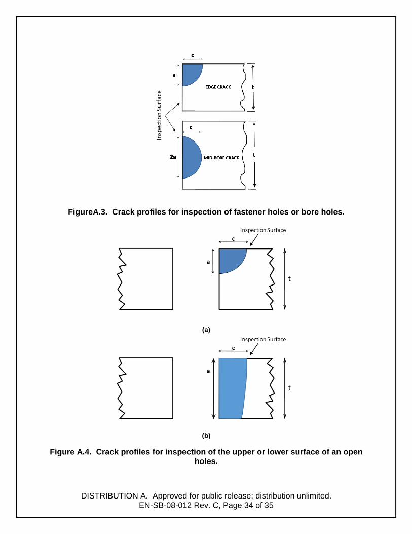
FigureA.3. Crack profiles for inspection of fastener holes or bore holes.
(a)
(b)
Figure A.4. Crack profiles for inspection of the upper or lower surface of an open holes.
Insp
ectio
n Su
rfac
e
DISTRIBUTION A. Approved for public release; distribution unlimited.
EN-SB-08-012 Rev. C, Page 35 of 35
Approved by: _________________________ _______________________ Dr. Gregory Schoeppner Charles A Babish IV Technical Advisor, Structures Technical Advisor, ASIP AFLCMC/EZFS AFLCMC/EZ WPAFB, Ohio WPAFB, Ohio Coordination Name Function Email Initials Robert Bair Structures Branch Chief [email protected] Mike Paulk Chief, AF NDI Office [email protected] John Brausch NDI Lead Engineer [email protected] Eric Lindgren NDE Technology Lead [email protected] David Campbell Tinker AFB NDI Manager [email protected] Ward Fong Hill AFB NDI Manager [email protected] Tommy Mullis Robins AFB NDI Manager [email protected]