STRUCTURED CODESIGN FOR MANYCORE SYSTEMS Jürg Gutknecht & Lisa (Ling) Liu, ETH Zürich Sofsem Novy...
65
STRUCTURED CODESIGN FOR MANYCORE SYSTEMS Jürg Gutknecht & Lisa (Ling) Liu, ETH Zürich Sofsem Novy Smokovec, January 2011
-
Upload
loren-herde -
Category
Documents
-
view
217 -
download
0
Transcript of STRUCTURED CODESIGN FOR MANYCORE SYSTEMS Jürg Gutknecht & Lisa (Ling) Liu, ETH Zürich Sofsem Novy...

STRUCTURED CODESIGN FOR MANYCORE SYSTEMSJürg Gutknecht & Lisa (Ling) Liu, ETH Zürich
Sofsem Novy Smokovec, January 2011

About Me
1968 System programming at Swissair
1977 PhD in Mathematics 1981 Joined Niklaus
Wirth's Lilith/ Modula team 1985 Sabbatial stay at
Xerox PARC 1986 Project Oberon
together with Wirth 2000 Academic languages
researcher at MSR

Outline of Talk
Context & Vision A Structured Approach Use Cases Programming Language & Compiler Power Management Codesign Hardware Library

Some context of the project and a vision
Context & Vision
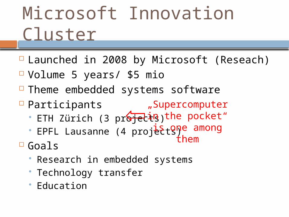
Microsoft Innovation Cluster
Launched in 2008 by Microsoft (Reseach) Volume 5 years/ $5 mio Theme embedded systems software Participants
ETH Zürich (3 projects) EPFL Lausanne (4 projects)
Goals Research in embedded systems Technology transfer Education
„Supercomputerin the pocket“ is one among them

Supercomputer in the Pocket
Manycore architecture for embedded systems on the basis of programmable hardware (FPGA)
High-performance computing in the small Generic technology for wide range of apps
Sensor driven medical IT Data streaming in financial apps Running robot with limb control Real time audio processing
Hardware/ software design from the ground up
will be focussed in this talk

People Involved
Microsoft Research Chuck Thacker (consultant)
ETH Zürich Niklaus Wirth (processor design) Jürg Gutknecht (project leader) Lisa (Ling) Liu (hardware design) Felix Friedrich (compiler)
University Hospital Basel Alexej Morozow (medical IT app)

The Vision
Custom hardware design for embedded systems
Programmers need no hardware knowledge
System design process at high level of abstraction
Fully automated mapping process to FPGA
FPGA resources are used efficiently

Semantic Gap
Object Thread Data structure Statement Communication I/O ...
Lookup tables (LUT)
Block RAMs (BRAM),
DSP slices …
Program Constructs FPGA Resources
Map

Big picture of our structured codesign approach
An Structured Approach
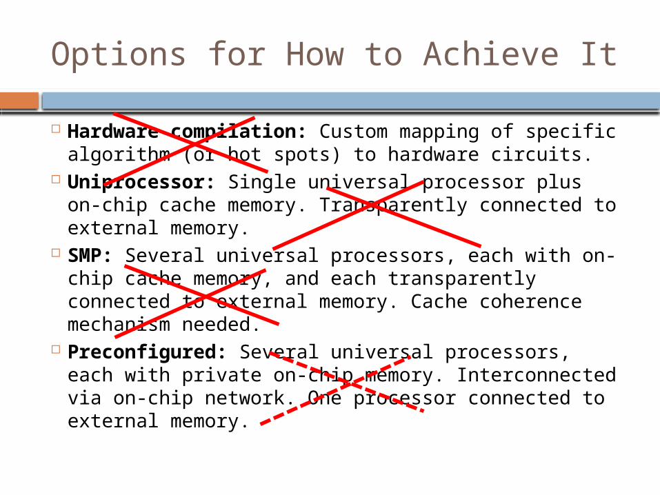
Options for How to Achieve It
Hardware compilation: Custom mapping of specific algorithm (or hot spots) to hardware circuits.
Uniprocessor: Single universal processor plus on-chip cache memory. Transparently connected to external memory.
SMP: Several universal processors, each with on-chip cache memory, and each transparently connected to external memory. Cache coherence mechanism needed.
Preconfigured: Several universal processors, each with private on-chip memory. Interconnected via on-chip network. One processor connected to external memory.

A Better Approach
Hardware/ software codesign based on a suitable high-level computing model and programming language
Fully automated mapping/ synthesizing to FPGA hardware based on suitable library of highly configurable hardware components
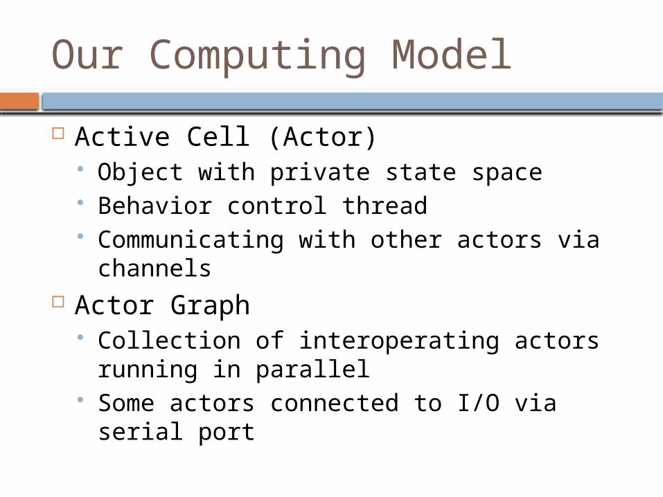
Our Computing Model
Active Cell (Actor) Object with private state space Behavior control thread Communicating with other actors via
channels Actor Graph
Collection of interoperating actors running in parallel
Some actors connected to I/O via serial port

Our Hardware Library
TRM processor (Tiny Register Machine) Extremely simple Two level pipelined instruction execution Several variants
VTRM (vectors via DSP), DTRM (DMA) Communication FIFO
Ring buffer Sizes 32, 64, 128, 1024
I/O controllers DDR2, CF, LCD, UART

Mapping
Actor
Communication channel
I/ O
TRM processor („core“)
Instruction memory Data memory FIFO buffer
I/ O controllers connected to cores
Actor Graph FPGA
Map

TRM/ FIFO Cooperation
TRM M
FIFO
FIFOchannel
channel
rec
vse
nd
•fully orchestrated by TRM•no interrupts!
Two data driven applications of our system
Use Cases

Realtime Multichannel ECG Monitor Analyze the activity of the heart, the
morphology of the corresponding waves, and the heart rate variability (HRV), with the aim of detecting and classifying potential anomalies
The signal to be analyzed decomposes into 8 physical channels, each of them sampled at 500 Hz

Decomposition into Actor Graph
Signal
input
Wave proc_
1
QRSdete
ct
HRV analys
is
Disease
classifier
Wave proc_
2
Wave proc_
8
ECGbitstream
outstream
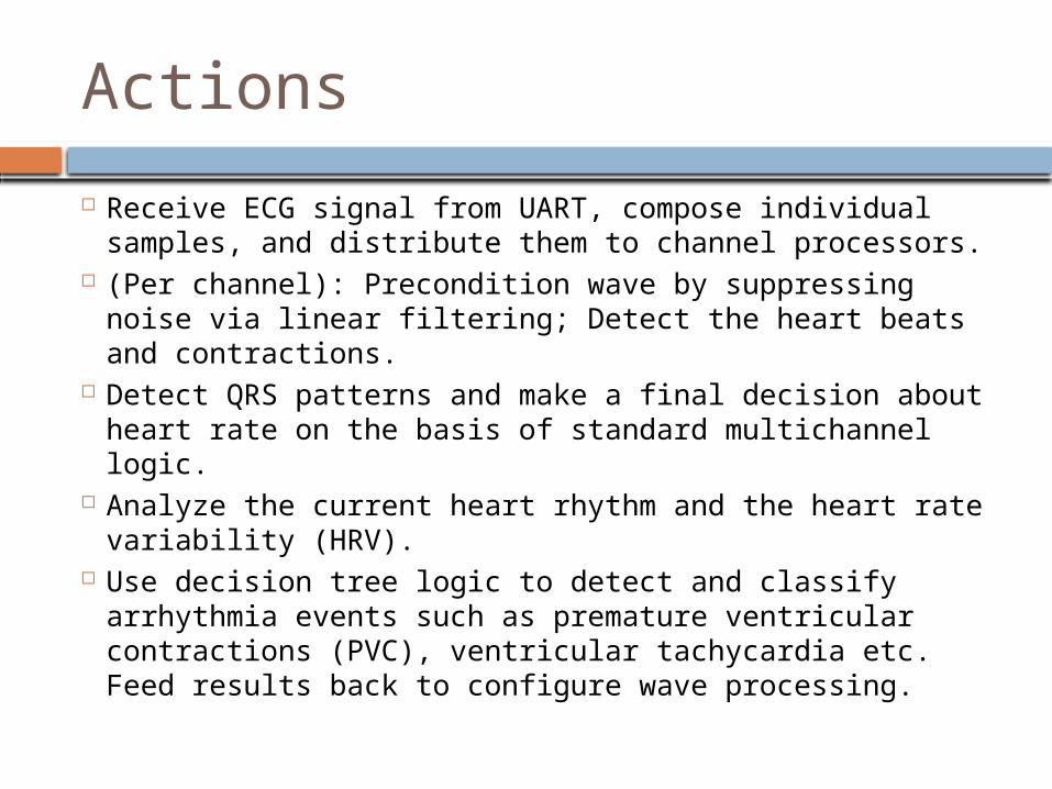
Actions
Receive ECG signal from UART, compose individual samples, and distribute them to channel processors.
(Per channel): Precondition wave by suppressing noise via linear filtering; Detect the heart beats and contractions.
Detect QRS patterns and make a final decision about heart rate on the basis of standard multichannel logic.
Analyze the current heart rhythm and the heart rate variability (HRV).
Use decision tree logic to detect and classify arrhythmia events such as premature ventricular contractions (PVC), ventricular tachycardia etc. Feed results back to configure wave processing.

Development board
Xilinx Virtex-5 FPGA

ECG
TRM12
UART
Ctrl
LCD
Ctrl
CFCtrl
RS232 CF
LCD
TRM11
TRM10
TRM2
TRM3
TRM9
TRM1
TRM4
FIFO1
FIFO8
FIFO9
FIFO16
FIFO17 FIFO18
FIFO19
FIFO20
FIFO33
FIFO34
ResultingFPGA
configuration
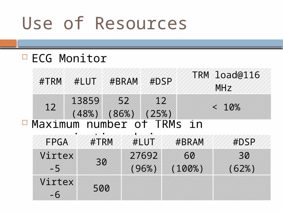
ECG Monitor
Maximum number of TRMs in communication chain
Use of Resources
#TRM
#LUT#BRA
M#DSP
TRM load@116 MHz
121385
9(48%)
52(86%)
12(25%)
< 10%
FPGA #TRM #LUT #BRAM #DSP
Virtex-5
3027692(96%)
60(100%)
30(62%)
Virtex-6
500

Preconfigured Version
Column 0
Column 1
Column 2
Column 3
H0H1H2H3
TRM1
TRM2
TRM3
TRM7
TRM8
TRM9
TRM4
TRM5
TRM6
TRM10
TRM11
TRM12
inbound arbiteroutbound arbiter
inbound arbiteroutbound arbiter
inbound arbiteroutbound arbiter
inbound arbiteroutbound arbiter
UART controller
CF controller
LCD controller
Virtex-5LX50T FPGA
CF
LCD
RS232
Xilinx ML505 board
ECG Sensor

Comparative Power Usage
Preconfigured FPGA (TRM, IM/ DM, I/O, interconnect)
Fully configurable
System
Quiescent
power (W)
Dynamicpower
(W)
Preconfigured
3.43823 0.58988
Dynamically
configured0.49742 0.48060
86% saving!

Graphics Based Motion Detection Problem: Detect moving objects in a
series of image frames Approach: Parallelize detection process
by domain decomposition (into 4 parts) Design: A reader process continuously
reads frames from external memory and forwards them to (4) part-detection processes running in parallel and reporting detected movements

FPGA Configuration

Performance Results
Data base 10 frames of resolution 576 x 768 (432 KP)
Estimated performance Transfer from external DDR2 memory ca. 40
MP/sec Computation: 4 x 31 MP/sec Total time used per frame 55 ms Total throughput 18 frames/ sec

Programming language & automated mapping
Program Language & Compiler

The ActiveCells Language
History & Profile Evolution of Pascal, Modula, Oberon Actor based Compositional
Active cell (Actor) Object with active behavior, communicating via
channels Assembly
Network of interoperating active cells Reusable software component with ports
interface

Example of Functional Actor
F = actor (in1, in2: instr; out: outstr); var i, j: integer;begin loop recv(in1, i); recv(in2, j); send(out, someOp(i, j)) endend

Example of User Interface Actor UI = actor (out1, out2: outstr; in: instr);
var i, j, k: INTEGER;begin loop RS232.RecvInt(i); RS232.RecvInt(j); send(out1, i); send(out2, j); recv(in, k); RS232.SendInt(k) endend

Examples of Assemblies
Assembly without ports
Assembly with ports
UIout1out2
inF
in1 in2
out
connect
Gin1 in2
out
Fin1 in2
outF
in1 in2
out
delegate
RS232 actor
in1 in2 in3 in4
out
A B
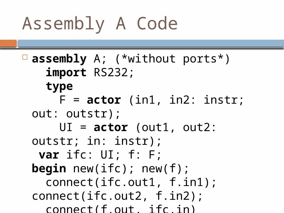
Assembly A Code
assembly A; (*without ports*) import RS232; type F = actor (in1, in2: instr; out: outstr); UI = actor (out1, out2: outstr; in: instr); var ifc: UI; f: F;begin new(ifc); new(f); connect(ifc.out1, f.in1); connect(ifc.out2, f.in2); connect(f.out, ifc.in)end A.

Assembly B Code
Assembly B (in1, in2, in3, in4: instr; out: outstr); (*with five ports*) type F, G = actor (in1, in2: instr; out: outstr); var f1, f2: F; g: G;begin new(f1); new(f2); new(g); connect(f1.out, g.in1); connect(f2.out2, g.in2); delegate(in1, f1.in1); delegate(in2, f1.in2); delegate(in3, f2.in1); delegate(in4, f2.in2); delegate(out, g.out)end B.
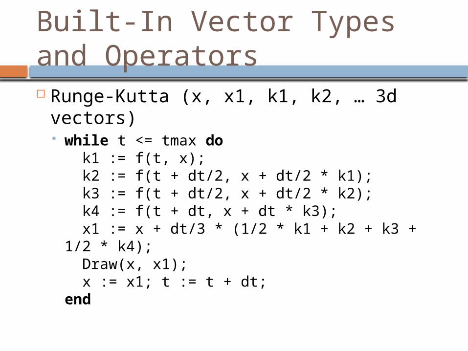
Built-In Vector Types and Operators Runge-Kutta (x, x1, k1, k2, … 3d vectors)
while t <= tmax do k1 := f(t, x); k2 := f(t + dt/2, x + dt/2 * k1); k3 := f(t + dt/2, x + dt/2 * k2); k4 := f(t + dt, x + dt * k3); x1 := x + dt/3 * (1/2 * k1 + k2 + k3 + 1/2 * k4); Draw(x, x1); x := x1; t := t + dt;end
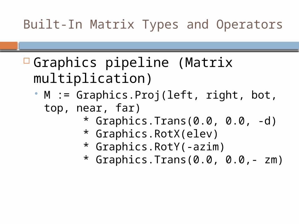
Built-In Matrix Types and Operators
Graphics pipeline (Matrix multiplication) M := Graphics.Proj(left, right, bot, top, near,
far) * Graphics.Trans(0.0, 0.0, -d) * Graphics.RotX(elev) * Graphics.RotY(-azim) * Graphics.Trans(0.0, 0.0,- zm)

Hybrid Compilation
Code body
Role Compilation method
Actor Business logic
Software compilation (TRM/ DSP)
Assembly
Creating actor graph (wiring)
Hardware compilation (Verilog)

Actor Code
F = actor (in1, in2: instr; out: outstr); var i, j: integer;begin loop recv(in1, i); recv(in2, j); send(out, someOp(i, j)) endend
TRM

Assembly Code
assembly B (in1, in2, in3, in4: instr; out: outstr); type F, G = actor (in1, in2: instr; out: outstr); var f1, f2: F; g: G;begin new(f1); new(f2); new(g); connect(f1.out, g.in1); connect(f2.out2, g.in2); delegate(in1, f1.in1); delegate(in2, f1.in2); delegate(in3, f2.in1); delegate(in4, f2.in2); delegate(out, g.out)end B.
Verilog

Automated Mapping to FPGA
source program
hybridcompiler
memory images.mem
Verilog codescripts
make.tcl, ram.bmm
Xilinxsynthesizer
bits
runtime
library
hardware
library
TRMcode

Program Model Refinement
Each thread may spawn any number mutually independent sub-threads
Advantages Allows (lock-free) fine-grained parallel
computing Requirements
Needs core clustering Needs runtime scheduling support Needs barrier mechanism
spawn
barrier
AA1
A2
A1
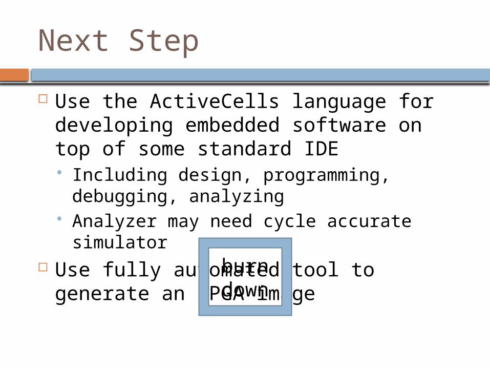
Next Step
Use the ActiveCells language for developing embedded software on top of some standard IDE Including design, programming, debugging,
analyzing Analyzer may need cycle accurate
simulator Use fully automated tool to generate an
FPGA imageburndown

Integrated HW/SW power management systemCollaboration with Prof. Shiao-Li Tsao, National Chiao Tung University, Taiwan
Power Management Codesign

Perfomance/ Energy Space

P/ E Profiling
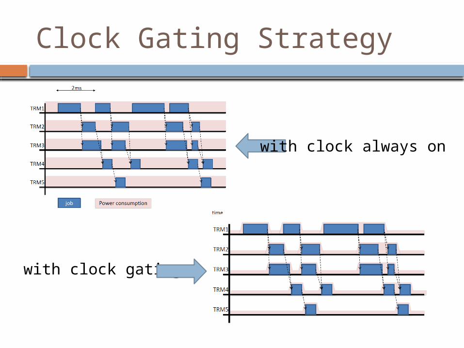
Clock Gating Strategy
with clock always on
with clock gating
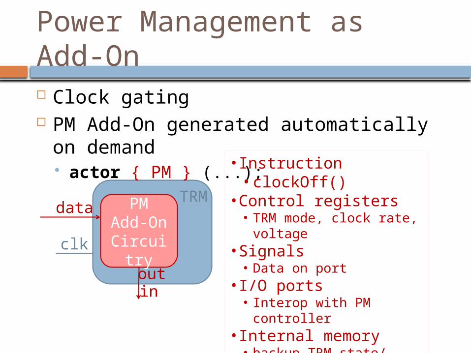
Power Management as Add-On Clock gating PM Add-On generated automatically on
demand actor { PM } (...);
PMAdd-On Circuitr
y
TRM
clk
outin
•Instruction• clockOff()
•Control registers• TRM mode, clock rate,
voltage•Signals
• Data on port•I/O ports
• Interop with PM controller•Internal memory
• backup TRM state/ registers
data

Clock Gating Off Procedure
Clo
ckM
an
ag
er
PMControll
er
PM Add-On Circuitr
y
TRMdata
clk
clk
outin
signal PM controller
stop clock
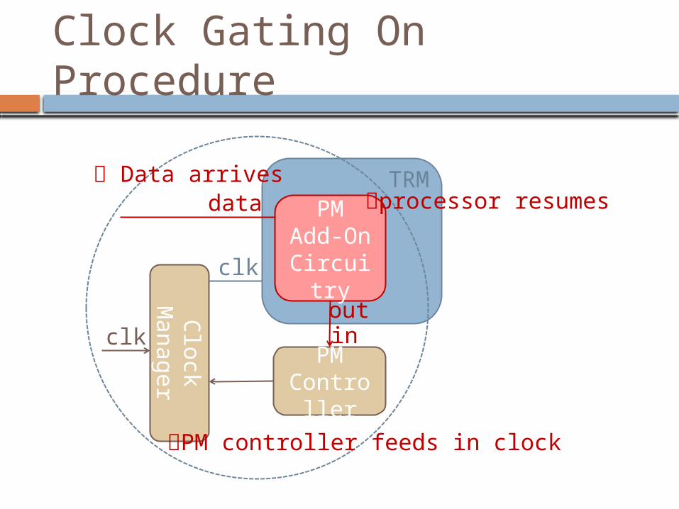
Clock Gating On Procedure
Clo
ckM
an
ag
er
PMControll
er
PM Add-On Circuitr
y
TRMdata
clk
clk
outin
Data arrives
PM controller feeds in clock
processor resumes
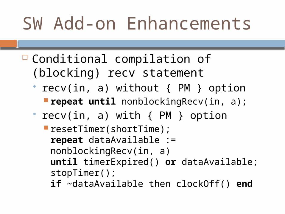
SW Add-on Enhancements
Conditional compilation of (blocking) recv statement recv(in, a) without { PM } option
repeat until nonblockingRecv(in, a); recv(in, a) with { PM } option
resetTimer(shortTime);repeat dataAvailable := nonblockingRecv(in, a)until timerExpired() or dataAvailable;stopTimer();if ~dataAvailable then clockOff() end

Next Step for Real Time Software begin { T } ... (* statements *) end
Adjust idle/ busy periods or clock rate between begin ... end to just meet indicated time limit T
Bridge the semantic gap between software functions and hardware circuitry
Hardware Library
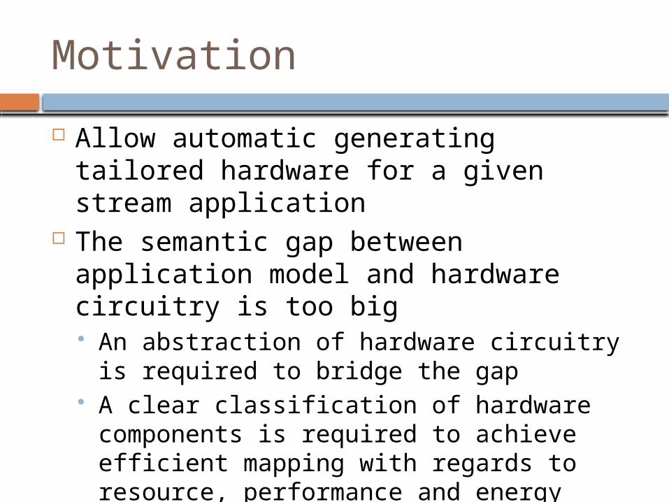
Motivation
Allow automatic generating tailored hardware for a given stream application
The semantic gap between application model and hardware circuitry is too big An abstraction of hardware circuitry is
required to bridge the gap A clear classification of hardware
components is required to achieve efficient mapping with regards to resource, performance and energy

Hardware Components Classification
Computation Components
• General purpose minimal machine: TRM
• Vector machine: VTRM
Communication Components
• FIFOs• 32 * 128• 512 * 128• 32, 64, 128, 1k * 32
Storage Components
• DMA + TRM: DTRM
• direct transfer vector from DDR to VTRM
I/O Components
• TRM + I/O access: IOTRM
• packing/unpacking I/O data to vectors or words

Abstraction
Hardware interfaces Computation components
#(IMB, DMB) TRM (input clk, rst, irq0, irq1, input[31:0] inbus,
output[5:0] ioadr, output iowr, iord, output[31:0] outbus)
#(VL, IMB) VTRM (input clk, rst, input[VL*32-1:0] inbus, output[5:0] ioadr, output iowr, iord, output[VL*32-1:0] outbus)
Communication components#(Width, Depth) ParChannel (input clk, rst, input[Width-
1:0] inData, input wreq, rdreq, output[Width-1:0] outData, output[31:0] status)

Storage component#(DataWidth) DTRM (input clk, rst,
input[DataWidth-1:0] inbus, output[5:0] ioadr, output iowr, iord, output[DataWidth-1:0] outbus)
IO component#(VL) IOTRM (input clk, rst, input [VL*32-1:0] inbus, output [5:0] ioadr, output iowr, iord, output[VL*32-1:0] outbus)

TRM (Tiny Register Machine)
2-address register machine (8 registers) Configurable instruction/ data memory Optional I/O controller added
IMemory(4K x 18
bits)
DMemory(1K x 32
bits)
Decoder
Registers18
32
ALU
116 MHz

Vector TRM
8 vector registers (each 8 32-bit floats) Vector add/ multiply takes 4 cycles Horizontal addition takes 10 cycles
IMemory(4K x 18
bits)
DMemory(8K x 32
bits)
TRM
Vector
256
256

DMA TRM
256 bits wide data bus Loading 256 bits from DMA takes 2
cycles Storing 256 bits to DMA takes 1 cycle
IMemory(4K x 18
bits)
DMemory(1K x 32
bits)TRM
DMA
I/O data bus
256
256

Area, Performance Features (on Virtex-5LX50T)
System clock speed: 116MHz TRM : 2% LUTs, 1 DSP, 5 cycles for multiplication VTRM
integer vector unit, VL=4: 8% LUTs, 8 DSPs, 5 cycles for Vector multiplication, 3 cycles for horizontal vector addition
Floating point vection unit, VL = 4: 18% LUTs, 9 DSPs DMA: 10% LUTs, 1 DSP, 2 cycles for loading a
block from DDR2 controller buffer, 1 cycle for writing a block into DDR2 controller buffer
IOTRM: 5% LUTs, 1 DSP, 2 cycles for loading a vector, 1 cycle for writing a vector

References
http://www.nativesystems.inf.ethz.ch/ Reference papers
Ling Liu, Oleksii Morozov, A Process-Oriented Streaming System Design Paradigm for FPGAs, Reconfig’2010, Cancun, Mexico, December 13-15, 2010.
Ling Liu, Oleksii Morozov, Yuxing Han, Jürg Gutknecht, Patrick Hunziker, Automatic SoC Design Flow on Many-core Processors: a Software Hardware Co-Design Approach for FPGAs, FPGA’2011, Monterey California, February 27 ~ March 1, 2011.

Reserve Slides
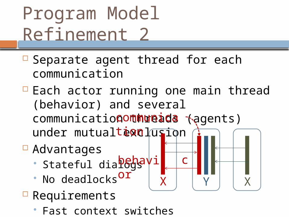
Program Model Refinement 2 Separate agent thread for each
communication Each actor running one main thread
(behavior) and several communication threads (agents) under mutual exclusion
Advantages Stateful dialogs No deadlocks
Requirements Fast context switches
Y XX
behavior
communication
c

Wiring Integrated into Actorsmodule M; var x1, x2: X; y: Y; type X = object … end X; Y = object … end Y; begin new(y); new(x1, y); new (x2, y)end M.
X = object var c: Y.C; activity A; var i, j, k: integer; begin (*behave*) …; c(i, j); …; c(k); … end A; procedure X (y: Y); begin (*build object*) …; new (c); … end X;begin new A (*launch behavior*)end X;
Y = object activity A; begin (*behave*) … end A; activity C; var u, v, w: integer; begin (*communicate*) …; accept(u, v); …; accept(w); … end C; procedure Y; begin (*construct*) … end Y; begin new A end Y;