College of LSA | U-M LSA U-M College of LSA€¦ · Created Date: 11/8/2007 1:27:17 PM

AD-A255 026 C,u T
N& SEP i 1992ý`,,Y
STRUCTURED ANALYSIS/DESIGN
LSA TASK 302
SUPPORT SYSTEM ALTERNATIVES
SUBTASK 302.2.3 & 302.2.4ALTERNATIVE SUPPORT PLANS &
UPDATED ALTERNATIVE SUPPORT PLANSAPJ 966-235
1'CENTFI
MILITARYAClENTIFICRESEARCH
_
92-241800.9IENIIUDII

SECURITY CLASSIFICATION OF THIS PAGE
Form Approved.REPORT DOCUMENTATION PAGE OMBNo. 0O74-8l
la. REPORT SECURITY CLASSIFICATION lb. RESTRICTIVE MARKINGSUNCLASSIFIED
2a. SECURITY CLASSIFICATION AUTHORITY 3. DISTRIBUTION/AVAILABILITY OF REPORT
2b. DECLASSIFICATION /DOWNGRADING SCHEDULE UNLIMITED
4. PERFORMING ORGANIZATION REPORT NUMBER(S) 5. MONITORING ORGANIZATION REPORT NUMBER(S)
6a. NAME OF PERFORMING ORGANIZATION 6b. OFFICE SYMBOL 7a. NAME OF MONITORING ORGANIZATION(If applicable)
AMCCOM, Army AMSMC-MAE-EA
6c. ADDRESS (City, State, and ZIP Code) 7b. ADDRESS (City, State, and ZIP Code)
Rock Island ArsenalRock Island, IL 61299-6000
&a. NAME OF FUNDING/SPONSORING 8b. OFFICE SYMBOL 9. PROCUREMENT INSTRUMENT IDENTIFICATION NUMBERORGANIZATION (If applicable)
8c. ADDRESS(City, State, and ZIP Code) 10. SOURCE OF FUNDING NUMBERSPROGRAM PROJECT TASK IWORK UNITELEMENT NO. NO. NO. jCCESSION NO.
11. TITLE (Include Security Classification) Structured Analysis and Structured Design for theLogistic Support Analysis (LSA) Tasks, LSA Subtask 302.2.3, "AlternativeSupport Plans", and 302.2.4, "Updated Alternative Support Plans" (A 966-235).12. PERSONAL AUTHOR(S)DUCLOS, RONALD SHEPHERD, NED kmk13a. TYPE OF REPORT 13b. TIME COVERED 14. DATE OF REPORT (Year, Month, Day) 715. PAGE COUNTFINAL FROM TO Dec 1989 152
16. SUPPLEMENTARY NOTATION
17. COSATI CODES 18. SUBJECT TERMS (Continue on reverse if necessary and identify by block number)
FIELD GROUP SUB-GROUP STRUCTURED ANALYSIS, STRUCTURED DESIGN, LOGISTICSUPPORT ANALYSIS, LSA, DATA FLOW DIAGRAMS, DFDs,PROCESSES, DATA FLOWS, DATA STORES, over
19, ABSTRACT (Continue on reverse if necessary and identify by block number)This report consolidates the Structured Analysis and Structured Design forthe Logistic Support Analysis (LSA) Tasks. Included are the Data FlowsDiagrams (DFDs) for the LSA Subtask 302.2.3, "Alternative Support Plans",and 302.2.4, "Updated Alternative Support Plans", with the correspondingdescriptions of the processes, data flows, data stores, and externalentities identified on each DFD. The DFDs are further developed intoprocedures which identifies how to use the data to carry out the processesand accomplish the LSA Subtask. Venture Evaluation Review Technique (VERT)Batch Input files are also provided to assist, as tools, giving bothtechnical and managerial aspects of a task.
20. DISTRIBUTION /AVAILABILITY OF ABSTRACT 21. ABSTRACT SECURITY CLASSIFICATIONX&IUNCLASSIFIED/UNLIMITED 0 SAME AS RPT. 0 DTIC USERS UNCLASSIFIED
22a. NAME OF RESPONSIBLE INDIVIDUAL 22b. TELEPHONE (Include Area Code) 22c. OFFICE SYMBOL
NED SHEPHERD (309) 782-2479 AMSMC-MAE-EA
DD Form 1473, JUN 86 Previor,s editionsare obsolete. .ECURil;Y CLASSIFICATION OF ;HIS PAGE

18Z SUBJECT TERMS - continued:EXTERNAL ENTITIES, PROCEDURES, VENTURE EVALUATION REVIEW TECHNIQUE,VERT, PROCESS FLOWS, OVERALL SYSTEMS DEVELOPMENT PROCESS, ALTERNATIVESUPPORT PLANS, UPDATED ALTERNATIVE SUPPORT PLANS

APJ 966-235
STRUCTURED ANALYSIS/DESIGN
LSA TASK 302SUPPORT SYSTEM ALTERNATIVES
SUBTASK 302.2.3 & 302.2.4 ; ,:,ALTERNATIVE SUPPORT PLANS &
UPDATED ALTERNATIVE SUPPORT PLANS ,' .
under
CONTRACT DAAA21-86-D-0025
for
HQ, US AMCCOMINTEGRATED LOGISTIC SUPPORT OFFICE
AMSMC-LSPROCK ISLAND, IL
DTIC QUALITY INSPECTED 3
by
AMERICAN POWER JET COMPANY
RIDGEFIELD, NJ FALLS CHURCH, VA
WILLIAMSBURG, VA ST. LOUIS, MO
December 1989

FOREWORD
APJ, under contract to HQs, AMCCOM, has initiated theautomation of the LSA Tasks (MIL-STD-1388-1), and theassessment of the ILS elements (AR 700-127). A major goal is tounify military and contractor approach to the performance of ILSand LSA.
Detailed to meet all requirements of ILS and LSA, theautomated process will continue to provide the flexibility inselecting tasks and elements to be addressed at each life cyclestage. A major advantage of this approach is to insure that theapplication of each task is consistent with prescribed Armypolicies and procedures.
This report consolidates the Structured Analysis andStructured Design under one cover for the respective LSA Tasks.Structured Analysis provides a logical model of the method toperform and LSA Task. This logical model facilitates thedevelopment of a Structured Design that provides the detailedprocedures to perform the analysis. Both the logical model anddetailed procedures are used to develop the application softwareprograms which will be provided to Government and contractorpersonnel to assist in the performance of the LSA Task.
Included in this report are the Data Flow Diagrams (DFDs)for LSA Subtask 302.2.3, "Alternative Support Plans" and302.2.4, "Updated Alternative Support Plans" as well as thecorresponding descriptions of the processes, data flows, datastores, and external entities identified on each DFD (Annex B).In addition, the DFDs are further developed into step-by-stepprocedures (Annex C) which identifies how to use the data tocarry out the processes which ultimately lead to accomplishingthe LSA Subtask.
To assist managers in planning and controlling this task,venture Evaluation Review Technique (VERT) Batch Input Files areprovided (Annex D). These VERT tools provide governmentagencies with complete packages to give contractors that coverboth technical and managerial aspects of a task. This approachestablishes a 4tandardized form of communication and managementbetween contractors performing the task and government personnelreviewing the task.
To view this work in context, Annex E of this report alsopresents a brief overview of Structured Analysis and its placein the overall systems development process. The overview andcertain portions of the introductory text are repeated verbatimin every report in this series so that each report is freestanding.
ii
TABLE OF CONTENTS
TITLE PAGEPurpose .............................................. 1Background ........................................... 1Scope ................................................ 1Structured Analysis and Design for LSA Subtask302.2.3 and 302.2.4 ................................. 2
LSA Subtask 302.2.3 Description ........................... 2LSA Subtask 302.2.4 Description ........................... 3Approach ............................................. 3VERT Diagrams ........................................ 4
ANNEX A:LSA Task 302 Description - Support SystemAlternatives ............. ..................... A-1
ANNEX B:LSA Subtask 302.2.3 & 302.2.4 - Alternative
Support Plans & Updated Alternative SupportPlans, Data Flow Diagrams, and DataDictionary .................................... B-i
ANNEX C:LSA Subtask 302.2.3 & 302.2.4 - AlternativeSupport Plans & Updated Alternative SupportPlans Structured Design ............................. C-1
ANNEX D:VERT Batch Input Files ......................... D-1
ANNEX E:Structured Systems Analysis - Fundamentals ..... E-I
LIST OF FIGURES
FIGURE NO. TITLE PAGE
1 Structured Analysis and StructuredSystems Design Organization ................. E-4
2 Standard DFD Symbol Definitions ............ E-5
iii

INTRODUCTION
PURPOSE
The purpose of this report series is to present the resultsof the APJ efforts under Contract DAAA21-86-D-0025 forcoordination with the AMCCOM Program Manager prior to in-depthprogramming of ILS and LSA functions and processes. LSA Task302, "Support System Alternatives" (LSA Subtask 302.2.3 and302.2.4 "Alternative Support Plans" and "Updated AlternativeSupport Plans") is addressed in this report.
BACKGROUND
The Department of the Army has a requirement for managementcontrol over contractor and Government agency response to therequirements of AR 700-127, "Integrated Logistic Support", andMIL-STD-1388-1, "Logistic Support Analysis". HQs AMCCOM hasinitiated action to structure each of the LSA tasks, theassessment of each ILS element, the form of the results, and thedetailed processed to insure consistency with current Armypolicies, procedures, and techniques.
This approach (undertaken by AMCCOM and APJ) will insureuniformity in efforts and products, reproducibility of analyses,and a well-defined structure which can be coordinated among allparticipants in the logistic process to arrive at commonunderstanding and procedures.
SCOPE
This report summarizes the results of the StructuredAnalysis of LSA Subtasks 302.2.3 and 302.2.4, "AlternativeSupport Plans" and "Updated Alternative Support Plans" andpresents the associated Data Flow Diagrams (DFDs) developed fromthe Structured Analysis. The portions of the Data Dictionaryrelating to labels, names, descriptions, processes, data flows,data stores, and external entities are included in their presentdegree of completeness. (The Data Dictionary is a "livingdocument" that evolves through the analysis and design process)
The Data Dictionaries developed for each of the individualLSA Subtasks are integrated together into a Master DataDictionary. Integration of the individual Data Dictionaryinvolves the combination of simular Data Flows, Data Stores, andExternal Entities. The resulting Master Data Dictionary maywell contain some minor differences from the definitions thatappear in this report. All processes, and of course, thecontent of the structured design will remain identical.
1

The Structured Design portion of this report develops theprocesses and data flows developed in the DFDs into procedureswhich are used to accomplish the LSA Tasks. The DFDs providethe method and the Design implements it, by formulating a guidefor programmers to write software applications.
This report presents a brief overview of StructuredAnalysis and its place in the overall systems design process toassist the reader who may not be fully briefed on the symbolsand conventions used. It is supported by Annex E, which defineseach element in Structured Analysis, and by a separate Glossary.
LSA SUBTASK 302.2.3 & 302.2.4 - DATA FLOW DIAGRAMS (DFD)
The Data Flow Diagram is a tool that shows the flow ofdata, (i.e., data flows from sources) and is processed byactivities to produce intermediate or final products.
The DFD provides a useful and meaningful partitioning of asystem from the viewpoint of identification and separation ofall functions, actions, or processes so that each can beintroduced, changed, added, or deleted with minimal disruptionof the overall program, i.e., it emphasizes the underlyingconcept of modularity and identifiable transformations of datainto actionable products.
A series of two (2) DFDs have been developed to structureboth LSA subtasks relative to plan development and update asfollows:
1. 302.2.3, "Alternative Support Plan"2. 302.2.4, "Updated Alternative Support Plan"
Four standard symbols are used in the drawing of a DFD (seeAnnex E, Figure 2).
A copy of each DFD is presented in Annex B, accompanied bythe Data Dictionary process elements. Each entry made in theDFDs has a corresponding entry in the Data Dictionary,immediately following each of the DFDs.
LSA SUBTASK 302.2.3 & 302.2.4 - DESCRIPTION
Both the 302.2.3 and 302.2.4 LSA subtasks addressthemselves to the development of viable Support PlanAlternatives and the update of each viable Support PlanAlternative. In all cases, a plan is developed for each viableSupport Concept Alternative fulfilling the needs of eachSystem/Equipment Alternative.
2

LSA Subtask 302.2.3 - Provides for:
1. Identification of the System/Equipment hardware belowthe Subsystem/Subequipment levels (i.e., indenturelevel 3 and lower).
2. The determination of the logistic support resourcesnecessary to maintain and operate the lower levelhardware.
3. The incorporation of the System/Subsystem orEquipment/Subequipment level viable Support Conceptsinto the Support Plan. This newly developed supportresource requirements incorporates with theestablished concept level resource requirement toarrive at a total support resource package coveringall indenture levels (from the Top level down) of theSystem/Equipment under consideration.
LSA Subtask 302.2.4 - Provides fcr the update of the viableSupport Plan after the plan has undergone Trade-Off Analysis inaccordance with LSA Task 303 or the viable Support ConceptAlternative has undergone update in accordance with Subtask302.2.2.
The descriptions and definitions of LSA Task 302 and LSAsubtasks 302.2.3 and 302.2.4 indicated in MIL-STD-1388-1A areincluded herein as Annex A.
APPROACH
The APJ approach to Structured Analysis of the LSA task is:
1. Scope the process defined in MIL-STD-1388-1A inthe context of the other LSA tasks.
2. Review the guidance provided in AMC PAM 700-11,"Logistics Support Analysis Review Team Guide".
3. Review the applicable Data Item Descriptions(DIDs) from the Acquisition Management Systemsand Data Requirements Control List (AMSDL)published by the Department of Defense.
4. Review all source documents referenced in theAMSDL as applicable to the referenced DIDs ofinterest.
3

5. Apply staff experience in logistic supportanalysis to assure that the topic has beenexhaustively addressed.
6. From the completed DFDs prepare the step-by-stepprocedures that form the structured design.
7. Review Data Item Description and other applicablematerial to develop output reports.
8. If required revise DFDs and Data Dictionary basedon preparation of detailed procedures.
9. Validate results in discussions with Armyactivities and personnel directly involved in theapplicable or related LSA tasks.
NOTE: Structured Analysis and preparation of Data FlowDiagrams (DFDs) was further assisted by theapplication of Structured Analysis software.Licensed by Index Technology Corporation,Excelerator provides for automated tracking ofnames, labels, descriptions, multiple levels ofdetail in the data flow diagrams, and industrystandards in symbols and diagramming practices.
VERT DIAGRAMS
The Venture Evaluation Review Technique (VERT) wasdeveloped as a network analysis technique to facilitatemanagement decision making. It allows systematic planning andcontrol of programs and enables managers to find solutions toreal life managerial problems. The VERT Diagrams and INputFiles for this task can be found in Annex D. In order tounderstand how these Input Files were developed, a briefdiscussion of the methodology used is provided. The sameexplanation is repeated verbatim in every report.
4

ANNEX A
LSA TASK 302SUPPORT SYSTEM ALTERNATIVES
LSA SUBTASKS 302.2.3 & 302.2.4ALTERNATIVE SUPPORT PLANS
ANDUPDATED ALTERNATIVE SUPPORT PLANS

ANNEX A
LSA TASK 302 DESCRIPTION
SUPPORT SYSTEM ALTERNATIVES
302.1 PURPOSE. To establish viable support systemalternatives for the new system/equipment for evaluation, trade-off analysis, and determination of the best system fordevelopment.
302.2 TASK DESCRIPTION
302.2.3 Develop and document viable alternative support plansfor the new system/equipment to a level of detail commensuratewith the hardware, software, and operational scenariodevelopment.
302.2.4 Update and refine the alternative support plans astrade-offs are conducted and the new system/equipment's designand operational scenario become better defined.
1/ Abstracted verbatim from MIL-STD-1388-1A, April 11, 1983,
Pages 36-37.
A-i

ANNEX B
LSA TASK 302SUPPORT SYSTEM ALTERNATIVES
SUBTASKS 302.2.3 & 302.2.4,ALTERNATIVE SUPPORT PLANS &
UPDATED ALTERNATIVE SUPPORT PLANS
DATA FLOW DIAGRAMS AND PROCESS DATA DICTIONARY

PROGRAM4 32.2.LT1OM /AB
hiaaAaZR S /8 302.2.1/
DATA FILM NTEIWrRSYTWOI 0..
ACTION ANALYSIS ALANAGE
TO TASSK
TASK~~RO 30 WSCRFK
30202.3.2
302.2. ALTRNAE SPPOT PA
CPROGRAM byr 510RV~~DAT byr 12
BDateM WORKd 2-EC9
Mar ~ ~ ~ ~ ~ ~ - ____ HM9 OMAIO BUCI

DATA PILE30.41
SBLSC 07-rRON TASK 303
SELECTEDSYSTEMEQUIPSI6WALTEANATMV
302.24.2 ROH TASKSZLICT302.2.2
DATA AILE
EEDIHERIM SVPAL SW? ~ SPCOMMIT CCgICEPT
D0C~STA~bOALTUIIATIV
DAT TASK
UPDAACK LSA
TO~~FRS TAKASiK DT3 0 2 . 2 . 2 3 0 2 2 . 4 .32p m 2 .2
REVISED C-TASK 30S3
ALTURIEATIV
A0LT. ALT SW? PLOn CYDATPTOASK 303 LJA a byO
RevCedIOW52
"DIN ab~qmmhlOE-S
MATZO

7T: 21-DEC-89 APJ 966-235 PAGE 1N: 15:43 PROCESSES EXCELERATOR 1.84
ame Label Description
302.2.3.1 SELECT ALT THE DATA IN ITS ENTIRETY REPRESENTING EACH UPDATED/REVISED/NEWSYS/EQUIP ALTERNATIVE SYSTEN/EQUIPMENT IS PAAGE AND IDENTIFIED AND READIED FORFOR USE IN THE DEVELOPMENT OF A SUPPORT PIN ALTERATIVE.ANALYSIS
302.2.3.2 SELECT TIE VIABLE SUPPORT CONCEPT ALTERNATIVES, BOTH NEW AND UPDATED,VIABLE SUP DEVELOPED IN PROCESS 302.2.1.6 AND 302.2.2.5, ARE IDENTIFIED AND THEIRCONCEPT DATA ACCUMULATED FOR EACH SYSTEWFEQUIPMIT UNDER CONSIDERATION.ALTERNATIV UNINCORPORATED TRADE-OFF ANALYSIS (TOA) ACTIONS AND ENGINEERING CHANG
ARE GATHERED AT THIS TIME AND RESUBMITTED FOR UPDATE OF EACH CONCEPT INPROCESS 302.2.2.5.
302.2.3.3 DEVELOP SYST/QUIPMEN HARDWARE INDENTURE LEVELS BELOW LEVEL 2 AS DEFINED INPOTENTIAL MIL-STD-881A ARE DEVELOPED AND PREPARED FOR ANY ADDITIONAL ILS ELU(ENTALTERNATIV AND READINESS CONSIDERATIONS. REQUANTIFICATION OF EITHER THE ILSSUPP PLANS ELEMENTS OR READINESS REQUIRCIENTS ARE ACCOMPLISHED IN PROCESS
302.2.1.5 OR 302.2.2.4.
302.2.3.4 VIABLE IN THIS PROCESS THE EXPANDED VIABLE SUPPORT CONCEPT ALTERNATIVE PLUSALTERNATIV THE INCLUSION OF ALL EXISTING LOWER INDMU LEVEL SUPPORTSUPP PLAN REQUIREMNTS CONSTITUTING THE POTENTIAL SUPPORT PLAN ARE RECEIVED AND
ANALYZED FOR VIABILITY AS A ALTERNATIVE SUPPORT PLAN (i.e., SUPPORTREQUIREENTS ARE WITHIN SUPPORT CONSTRAINTS). SELECTED SUPPORT PLANALTERNATIVES AND THEIR DOCUMENTATION ARE RETAINED FOR TRADEOFF ANALYSISIN LSA TASK 303.
302.2.4.1 SELECT UP- SYSTEN/EQUIPMENT ALTERNATIVES HAVING UNDERGONE TRADE-OFF ANALYSIS ORDATED SYS/ NEW SYSTEM/EQUIPHENT ALTERNATIVES DEVELOPED AS A RESULT OF TRADE-OFFEQPT FOR ANALYSIS ARE IDENTIFIED AND READIED FOR ANALYSIS AND USE IN THE UPGRADEANALYSIS OF THE SUPPORT PLAN ALTERNATIVE.
302.2.4.2 SELECT FROM THE UPDATED VIABLE SUPPORT CONCEPT PROCESSED IN SUBTASK 302.2.2.1,UPDATED THOSE CONCEPTS REPRESENTING THE SYSTE /EQUIPHENT ALTERNATIVES UNDERVIABLE SUP CONSIDERATIONS ARE SELECTED AND ACCUMULATED FOR INTEGRATION WITH THECONCEPT UPDATED DOCUMETATION AND REPRESENTS THE BALANCE OF UPDATED LOWER LEVEL
POTENTIAL ALTERNATIVE SUPPORT REQUIREMNTS.
302.2.4.3 UPDATED LSA TOA AND ENGINEERING TOA ACTIONS AFFECTING SUPPORT CONSIDERATIONSPOTENTIAL FOR LEVEL 3 PER MIL-STD-881A AND LOWER INDENTU LEVEL HARDWARE AREALT SUPP INCORPORATED INTO EACH POTENTIAL SUPPORT PLAN ALTERNATIVE AND, WHEREPLANS APPLICABLE, THE DATA IS ACCUMULATED AND UTILIZED IN SUBTASK 302.2.2 TO
UPDATE ILS ELEMENT DOCMNTATION AND READINESS REQUIRp N DATA.
302.2.4.4 UPDATED THE UPDATED QUANTIFIED ILS MELENT DOCUMENTATION AND UPDATED QUANTIFIEDVIABLE ALT READINESS DATA ARE ASSESSED FOR COMPATIBILITY WITH THE CONSTRAINTSSUPPORT ESTABLISHED FOR THE SYSTEK/EQUIPNENT. WHERE REQUIREIENTS EXCEED THEPLAN CONSTRAINT THRESHOLD LEVEL, THE ALTERNATIVE SUPPORT PLAN IN ITS
ERYIRETY, SHALL BE CONSIDERED UNACCEPTABLE. ACCEPTABLE SUPPORT PLANALTERNATIVE DOCUMENTATION ARE READIED FOR FURTHER TOA ACTIONS PER LSATASK 303.
B-3

M: 21-DEC-89 APJ 966-235 PAE[ME: 15:42 DATA FLOW EXCELERATOR 1.84
Name Label Description
BCS BASELINE THE BASELINE COMPARISON SYSTEM DOCMWATION PROVIDES INPUT DATA FORCOMPARISON THE ANALYSIS AND PROJECTION OF POTENTIAL SYSTlE4 READINESS,SYSTEM MANPOER AND PERSONNEL REQUIREMENS, AND 0 & S COSTS FOR EACHDATA POTENTIAL SUPPORT CONCEPT FOR EACH ALTERNATIVE SYSTEK/EQUIPMENT.
REFERENCE: LSA TASK 203.
ENG/CRANGE/DOC ENGINEERING ACRONYM: TOA, ECNCHANGEDOUM ATIO ENGINEERING CHANGE DOCUMENTATION - ENGINEERING TOA ACTION,
DOCUMENTATION, UNINCORPORATED EC1's, NEW OR EXPANDED SYSTE4/EQUIPMENTDEFINITION OR OTHER ENGINEERING EFFORTS AND DOCUMENTATION HAVING ABEARING ON THE DEVELOPMENT OR REQUIRING UPDATED OF THE SUPPORT CONCEPTOR THE SUPPORT PLAN.
ENG/DATA ENGINEERING ENGINEERING DRAWINGS, PARTS LISTS AND OTHER ENGINEERING. DOCUMENTATIONDATA DEFINED IN DOD-STD-1000 AND MIL-STD-100 HAVING A BEARING ON THE
DEVELOPMENT OR UPDATE OF THE SUPPORT CONCEPT, SUPPORT PLAN OR OTHER IISACTIVITY.
INIT/ACT INITIATION ACRONYMS: ILS - INTEGRATED LOGISTIC SYSTEMSACTION
THE REQUIRED ACTIONS OF THOSE (IF MORS THAN ONE) ACTIVITIES NECESSARYTO ACTUATE AN ILS UELENT ASSESSMENT FOR A SYSTEM AND/OR EQUIPMENTPROVIDES THE FORMAL HTORIZATION FOR THE PERFORMANCE Of AN 115 EFFORT.
JSOR JOINT ACRONYM: JSOR - JOINT SERVICES OPERATIONAL REQUIREMENTSSERVICESOPERATIONAL PORTION OF THE JSOR DATA ARE UTILIZED TO ESTABLISH THE POTENTIALREQUIREMENTS SUPPORT CONCEPTS, READINESS FACTOR, AND COSTS INORDER TO DETERMINE THE
VIABLE SUPPORT CONCEPT ALTERNATIVES.
NEW/REV/UPDTD/ILS/DA NEW REVISED ACRONYMS: ILS - INTEGATED LOGISTIC SYSTEMUPDATED ILSMOM DATA NEW/REVISED/UPDATED ILS ELUENT DATA - DATA AFFECTING EXISTING
QUANTIFIED ILS ELEMENTS AND THEIR DOCUMENTATION ARE ACCUMULATED FORCONSIDERATION IN THE REVISION AND/OR UPDATE OF THE QUANTIFIED DATA.
REW/REV/UPDTD/READ/D NEW REVISED NEW/REVISED/UPDATED READINESS DATA - DATA AFFECTING EXISTING QUANTIFIEDUPDATED READINESS REQUIR•MENTS AND THEIR DOCUMENTATION ARE ACCUMULATED FORREADINESS CONSIDERATION IN THE REVISION AND/OR UPDATE OF THE QUANTIFIED DATA.DATA
POT/SUPP/PLAN/ALT POTENTIAL POTENTIAL SUPPORT PLAN ALTERNATIVE - THE INITIAL COMPILATION OF THESUPPORT PLAN ALTERNATIVE SUPPORT CONCEPT, THE IDENTIFIED LOWER INDENTURE LVALTERNATIVE HARDWARE AND THEIR SUPPORT REQUIREPMNTS.
REV/QUANT/ILS/EE/DA REVISED UP- ACRONYMS: TOA, ILSDATED QUANTILS ELENS REVISED/UPDATED QUANTIFIED ILS ELEMENT DATA - REVISED AND/OR UPDATED ILSDATA ELEMENTS AND THEIR DOCUMENTATION REFLECTING TOA ACTIONS AND OTHER
CHANGES OR CONSIDERATIONS HAVING A BEARING ON REQUIRED SYSTD4/EQUIPMENTLOGISTIC SUPPORT.
B-4
MTE: 21-DEC-89 APJ 966-235 PAGS 2US: 15:42 DATA FLOW EXCELER 1.84
Name Label Description
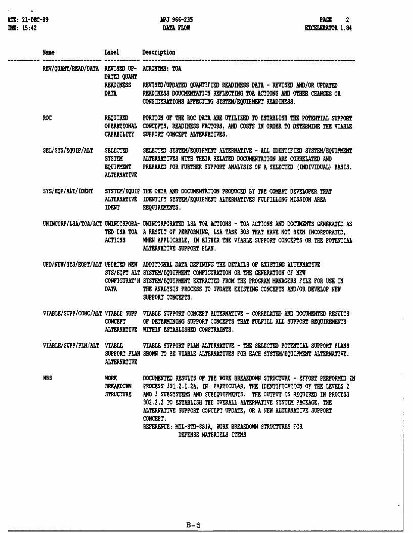
RCV/QUANT/READ/DATA REVISED UP- ACRONYM: TOADATED QUANTREADINESS REVISED/UPDATED QUANTIFIED READINESS DATA - REVISED •MD/OR UPDATEDDATA READINESS DOUCHENTATION REFLECTING TOA ACTIONS MAD OTHER CHANGES OR
CONSIDERATIONS AFFECTING SYSTW/EQUIPMENT READINESS.
ROC REQUIRED PORTION OF THE ROC DATA ARE UTILIZED TO ESTABLISH THE POTENTIAL SUPPORTOPERATIONAL CONCEPTS, READINESS FACTORS, AND COSTS IN ORDER TO DETERMINE THE VIABLECAPABILITY SUPPORT CONCEPT ALTERNATIVES.
SEL/SYS/EQUIP/ALT SELECTED SELECTED SYSTEM/EQUIPHENT ALTERNATIVE - ALL IDENTIFIED SYSTED/EQUIPMENTSYSTEM ALTERNATIVES WITH THEIR RELATED DOCUMENTATION ARE CORRELATED ANDEQUIPMENT PREPARED FOR FURTHER SUPPORT ANALYSIS ON A SELECTED (INDIVIDUAL) BASIS.ALTERNATIVE
SYS/EQP/ALT/IDENT SYSTER/EQUIP THE DATA AND DOCUMENTATION PRODUCED BY THE COMBAT DEVELOPER THATALTERNATIVE IDENTIFY SYSTEN/EQUIPMENT ALTERNATIVES FULFILLING MISSION AREAIDENT REQUIRENENTS.
UNINCORP/LSA/TOA/ACT UNINCORPORA- UNINCORPORATED LSA TOA ACTIONS - TOA ACTIONS AND DOCUMENTS GENERATED ASTED LSA TOA A RESULT OF PERFORMING, LSA TASK 303 THAT HAVE NOT BEEN INCORPORATED,ACTIONS WHEN APPLICABLE, IN EITHER THE VIABLE SUPPORT CONCEPTS OR THE POTENTIAL
ALTERNATIVE SUPPORT PLAN.
UPD/NEW/SYS/EQPT/ALT UPDATED NEW ADDITIONAL DATA DEFINING THE DETAILS OF EXISTING ALTERNATIVESYS/EQPT ALT SYSTEf/EQUIPMENT CONFIGURATION OR THE GENERATION OF NEWCONFIGURAT'N SYSTEK/EQUIPHENT EXTRACTED FROM THE PROGRAM MANAGERS FILE FOR USE INDATA THE ANALYSIS PROCESS TO UPDATE EXISTING CONCEPTS AND/OR DEVELOP NEW
SUPPORT CONCEPTS.
VIABLE/SUPP/CONC/ALT VIABLE SUPP VIABLE SUPPORT CONCEPT ALTERNATIVE - CORRELATED AND DOCUMENTED RESULTSCONCEPT OF DETERMINING SUPPORT CONCEPTS THAT FULFILL ALL SUPPORT REQUIREMENTSALTERNATIVE WITHIN ESTABLISHED CONSTRAINTS.
VIABLE/SUPP/PLN'ALT VIABLE VIABLE SUPPORT PLAN ALTERNATIVE - THE SELECTED POTENTIAL SUPPORT PLANSSUPPORT PLAN SHOWN TO BE VIABLE ALTERNATIVES FOR EACH SYSTEl/EQUIPMENT ALTERNATIVE.ALTERNATIVE
NBS WORK DOCUMENTED RESULTS OF THE WORK BRE.ADOWN STRUCTURE - EFFORT PERFORMED INBREAKDOWN PROCESS 301.2.1.2A, IN PARTICUIAR, THE IDENTIFICATION OF THE LEVELS 2STRUCTURE AND 3 SUBSYSTEMS AND SUBEQUIPMENTS. THE OUTPUT IS REQUIRED IN PROCESS
302.2.2 TO ESTABLISH THE OVERALL ALTERNATIVE SYSTE4 PACKAGE, THEALTERNATIVE SUPPORT CONCEPT UPDATE, OR A NEW ALTERNATIVE SUPPORTCONCEPT.REFERENCE: MIL-STD-881A, WORK BREAKDOWN STRUCTURES FOR
DEFENSE MATERIELS ITEMS
B-5

',AT: 21-DEC-89 APJ 966-235 PAG 1'29U: 15:42 DATA STORE EX"CELERATOR 1.84
NRae Label Description
P14/DF PROGRAM MANAGER CONTAINS THOSE FILES AND DATA WHICH ARE NORALLY DEVELOPED BY AND/ORDATA FILE RETAINED BY THE PROGRAM HMGER FOR PROPER MANAQMDET OF THE DEVELOPMENT
PROGRAM. THESE FILES INCLUDE:1. ENGINEERING DRAWING2. ENGINEERING CHARACTERISTICS3. DT/OT RESULTS4. CONCEPT FORIILATION PACKAGZ (CFP)5. DESIGN CONCEPT PAPER (DCP)6. TYPE TECHNICAL REVIEWS REWUIRED7. MILESTONE SCHEDULES8. FUNDING PROFILES9. REQUIRED OPERATIONAL CAPABILITIES (ROC)
10. ITE•/EQUIPHENT SPECIFICATIONS11. ITEM/EQUIPHENT MISSIONS & FUNCTIONS12. EQUIPMENT, MANPOWER, AND TECHNICAL RISK ASSESSMENTS (FROM
LSA TASK 301.2.313. TRADE OFF DETERMINATION ANALYSIS (TOD)14. TRADE OFF ANALYSIS (TOA)15.BEST TECHNICAL APPROACH ANALYSIS (BTA)16. COST AND OPERATIONAL-EFFECTIVENESS ANALYSIS (COEA)
B-6

T: 21-DEC-89 APJ 966-235 PAGE 1MH: 15:42 ETEN ENITY EXCELERATOR 1.84
Name Label Description------ ------------------ ------------------------------------------------------------------------
PM/ILSMT PROGRAM THE PROGRAM MANAGER OR THOSE ACTIVITIES, AGENCIES, OR AUTHORITIES THATMANAGER ARE RESPONSIBLE FOR THE INITITATION OF THE REQUIREMENT FOR AN ILSDATA FILE ELEIENT ASSESSMIT DURING A DEVELOPMENT PROGRAM FOR A SYSTEM AND/OR
EQUIPMENT IN ACCORDANCE WITH AR 700-127. THE IEY ACTION (OUTPUT)REQUIRED OF THIS EXTERNAL ENTITY IS THE DIRECTIVE, AUTHORITY, OR OTHERDOCUMENTATION THE INITIATES THE REQUIRMfT FOR THE APPLICATION OF THISILS ASSESSMENT TO A SPECIFIC SYSTEM/EQUIPHENT DEVELOPMENT PROGRAM AT ASPECIFIED POINT IN ITS LIFE CYCLE.
B-7
ANNEX C
SUBTASK 302.2.3 & 302.2.4ALTERNATIVE SUPPORT PLANS &
UPDATED ALTERNATIVE SUPPORT PLANS

SUBTASK 302.2.3ALTERNATIVE SUPPORT PLANS
PROCESS 302.2.3.1 - Select System/Equipment Alternativefor Analysis
PURPOSE:
To identify the System/Equipment Alternative and obtain therelated engineering documentation originally developed inProcess 302.2.1.1 or by the Combat Developer.
PROCEDURES:
1. From Subtask 302.2.1 and 302.2.2, obtain the previouslydeveloped technical information identifying each viableSystem/Equipment Alternative, as well as the following:
a. The Baseline Comparison System documentationapplicable to each System/Equipment Alternative.
b. All developed and completed quantitative andqualitative forms (if any) applicable to each System/Equipment Alternative.
C. All engineering data (including engineering drawings)applicable to and utilized in the development of eachSystem/Equipment Alternative.
2. If not accomplished, package each set of documentation,including the completed forms and their background data, torepresent each viable System/Equipment Alternative.
3. Select one (1) System/Equipment Alternative (if more thanone), and its related documentation package for analysis inProcesses 302.2.3.2 through 302.2.3.4.
NOTE: Repeat the System/Equipment Alternative selectionprocess and analysis until all System/EquipmentAlternatives have undergone and completed thisSubtask in its entirety.
C-1

REFERENCES:
The following references may be useful:
- Program Manager's Data File- Acquiring Activity File- LSA Task 203, Comparative Analysis Documentation- AR 700-127, Integrated Logistic Support- AMC/TRADOC PAM 70-2, Materiel Acquisition Handbook
Chapters 9 & 10.
PROCESS 302.2.3.2 - Select Viable Support Concept Alternatives
PURPOSE:
To identify those Support Concept Alternatives provenviable and applicable to the System/Equipment Alternative underconsideration.
PROCEDURE:
1. From Subtasks 302.2.1 and/or 302.2.2, or from documentationprepared using APJ Report 966-234, "Support SystemAlternatives", paragraph l.b of Process 302.2.3.1, identifyand obtain all viable Support Concept Alternativesapplicable to the System/Equipment under consideration.
2. From LSA Trade-Off Analysis (TOA) activities in Task 303,or from the Program Manager's Data File, identify andobtain any outstanding documentation relative to TOAactions and results that have not been incorporated in allor any existing viable Support Concept Alternatives.Review the documentation and determine the following:
a. Review each ILS element to identify changes torequirements affecting the System/Subsystem supportconcept.
b. Identify existence of changes in the following areasof the System/Subsystem levels of Alternatives:
(1) Functional characteristics(2) Operational characteristics(3) Configuration characteristics(4) Environmental conditions.
C-2

LSA TOA genezated changes affecting all or any existingviable Support Concept Alternative shall have the LSA TOAdocumentation accumulated for further analysis and considerationin accordance with the update provisions of LSA Subtask 302.2.2.
3. Perform the same review and data accumulation as outlinedin paragraph 2 above, except substitute outstandingengineering TOA documentation, Engineering Change Notices(ECNs), and any other Engineering Change/Update Documentsthat could have a bearing on the viability of existingSupport Concept Alternatives.
NOTE:- Viable Support Concept Alternatives affected by
Engineering changes shall be updated simultaneouslywith any LSA TOA generated changes in accordancewith the provisions of Subtask 302.2.2.
- As Support Concept Alternatives only encompassLevels 1 and 2 equipments, as defined in MIL-STD-881A, any data accumulation pertaining to lowerindenture levels of the System/Equipment underconsideration shall be retained for use inestablishing the overall support plan (Ref.: APJReport 966-234 "Support System Alternatives",Processes 302.2.3.3 and 302.2.3.4).
REFERENCES:
The following references may be useful:
-. Program Manger's Data File- LSA Task 303, Evaluation of Alternatives and Trade-off
Analysis- MIL-STD-881A, Work Breakdown Structure- AMC/TRADOC PAM 70-2, Materiel Acquisition Handbook
Chapters 9, 10, and 12- AR 70-37, Configuration Management- MIL-STD-480, Configuration Management- MIL-STD-483, Configuration Management Practices in
Systems, Equipments, Munitions and Computer Programs- MIL-T-60530, Technical Data Packages for AMC Materiel
C-3

PROCESS 302.2.3.3 - Develop Potential Alternative Support Plans
PURPOSE:
To establish the base that will constitute the initialformulation and identification of all possible support plansthat can be applied towards a given System/EquipmentAlternative.
NOTE: The analyst shall keep in mind that every viablesupport concept alternative requires thegeneration of a support plan.
1. Establish/complete/enlarge, as applicable, Level 3requirements of the Work Breakdown Structure documentation perMIL-STD-881A by performing the following:
a. From LSA Subtask 302.2.2 - "Updated Support SystemAlternatives", obtain the Work Breakdown Structuredocumentation applicable to the System/EquipmentAlternatives under considerations.
b. From the Program Manager's Data File, obtain thefollowing data identifying the current designparameters:
(1) Detail engineering drawings, including thesub-subsystem/sub-subequipment and all lowerindenture levels of the system/equipment.
(2) Approved ECNs not incorporated in engineeringdocumentation.
(3) Engineering TOA actions and results whosedocumentation have not been incorporated intothe engineering drawings or related engineeringdata.
(4) Baseline Comparison System documentationrepresenting the system/equipment underconsideration.
(5) ROC & JSOR
C-4
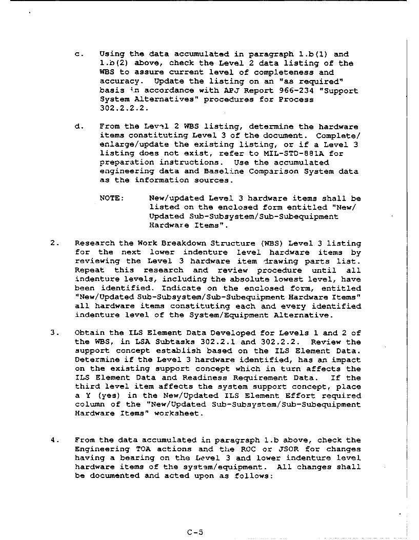
c. Using the data accumulated in paragraph l.b(1) andl.b(2) above, check the Level 2 data listing of theWBS to assure current level of completeness andaccuracy. Update the listing on an "as required"basis 4.n accordance with APJ Report 966-234 "SupportSystem Alternatives" procedures for Process302.2.2.2.
d. From the Levil 2 WBS listing, determine the hardwareitems constituting Level 3 of the document. Complete/enlarge/update the existing listing, or if a Level 3listing does not exist, refer to MIL-STD-881A forpreparation instructions. Use the accumulatedengineering data and Baseline Comparison System dataas the information sources.
NOTE: New/updated Level 3 hardware items shall belisted on the enclosed form entitled "New/Updated Sub-Subsystem/Sub-SubequipmentHardware Items".
2. Research the Work Breakdown Structure (WBS) Level 3 listingfor the next lower indenture level hardware items byreviewing the Level 3 hardware item drawing parts list.Repeat this research and review procedure until allindenture levels, including the absolute lowest level, havebeen identified. Indicate on the enclosed form, entitled"New/Updated Sub-Subsystem/Sub-Subequipment Hardware Items"all hardware items constituting each and every identifiedindenture level of the System/Equipment Alternative.
3. Obtain the ILS Element Data Developed for Levels 1 and 2 ofthe WBS, in LSA Subtasks 302.2.1 and 302.2.2. Review thesupport concept establish based on the ILS Element Data.Determine if the Level 3 hardware identified, has an impacton the existing support concept which in turn affects theILS Element Data and Readiness Requirement Data. If thethird level item affects the system support concept, placea Y (yes) in the New/Updated ILS Element Effort requiredcolumn of the "New/Updated Sub-Subsystem/Sub-SubequipmentHardware Items" worksheet.
4. From the data accumulated in paragraph l.b above, check theEngineering TOA actions and the ROC or JSOR for changeshaving a bearing on the Level 3 and lower indenture levelhardware items of the system/equipment. All changes shallbe documented and acted upon as follows:
C-5
a. Review the engineering data and any engineering TOAactions and data identifying the followingcharacteristics of all WBS Level 3 hardware itemsand all lower level subsystem/subequipment componentsand assemblies:
(1) Functional characteristics(2) Operational characteristics(3) Environmental conditions(4) Configuration characteristics
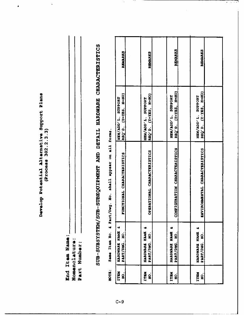
Identified characteristics and conditions affectingexisting ILS element data or readiness requirements shallbe listed on the enclosed form entitled "Sub-Subsystem/Sub-Subequipment and Detail Hardware Characteristics".
b. Revised ROC or JSOR documentation, if any, shall bereviewed for changes, additions, and deletionsaffecting any of the existing ILS elements data andreadiness requirements data for any level ofsystem/equipment hardware. Indicate any changes,additions, or deletions to hardware items on the formentitled: New/Updated Sub-Subsystem/Sub-Subequipmentand Detail Hardware Characteristics". Similarly,changed equipment characteristics and conditions shallbe indicated on the form entitled: "Sub-Subsystem/Sub-Subequipment and Detail HardwareCharacteristics"/
c. Upon completion of the forms mentioned in a and babove, check each new Hardware and Characteristicslisting therein for existing ILS element data coverageand Readiness Requiiement data coverage in theBaseline Comparison System documentation. Coveragesthat are complete and usable "as is" shall beincorporated as part of the Potential AlternativeSupport Plan. All other hardware and characteristicslistings on the two forms shall undergo assessment andanalysis in accordance with LSA Subtask 302.2.1 and302.2.2 and Processes 302.2.1.5A and 302.2.2.4described in APJ Report 966-234 "Support SystemAlternatives". Attach all ILS and Readiness forms tothe completed "New/Updated Sub-Subsystem/Sub-Subequipment Hardware Items" form and "Sub-Subsystem/Sub-Subequipment and Detail HardwareCharacteristics" form.
C-6
REFERENCES:
The following references may be useful:
- MIL-STD-881A, Work Breakdown Structure- Program Manager's Data File- LSA TAsk 203, Comparative Analysis- AMC/TRADOC PAM 70-2, Materiel Acquisition Handbook,
Chapters 3, 9 & 12- AR 70-37, Technical Data Packages.
PROCESS 302.2.3.4 - Viable Support Plan Alternative
PURPOSE:
To establish Viable Support Plan Alternatives that willsatisfy the functional and operational requirements of theSystem/Equipment Alternative.
PROCEDURES:
1. Review the completed, updated Readiness forms developed inProcess 302.2.2.4 (see APJ Report 966-234 for a descriptionof the process) and compare the Readiness constraints withthe calculated Sub-Subsystem/Sub-Subequipment and lowerindenture level hardware Readiness requirements. Where thecalculated requirements exceed the established LSA Subtask303.2.2 "Support System Alternatives", threshold level ofthe Sub-Subsystem/Sub-Subequipment and lower indenturelevel hardware constraints (if any), or requirements causethe System/Subsystem constraints to be exceeded, thepackage representing the Viable Support Concept for theSystem/Subsystem/Equipment/Subequipments (Levels 1 and 2per MIL-STD-881A) under consideration shall be consideredunacceptable.
2. For LSA Task 303 purposes, consolidate the ViableAlternative Support Concept Data with the Level 3 and lowerindenture level hardware data which represents the supportneeds of the system/equipment under consideration.
C-7

H 0a A~
1-4 1440o$40
0 ~ ~~~~ of___ OR _______
04.0
> 14 __ _ _ _ _
E4Y
.94 H 1 ._ _ _ 4
Ot ~~ $4 )
C)14 44 00
H 0m 0 M0tog EA)N
o f>0 0
a 04ul00 .1 "QC
4 At $4 r-4
4-) a w 9
414
C- 8
H I I1
14
0;0
A 0 0-4 0 ~ 02 OR
a$ as 00. 0.-CD U t ý 0
0-
.JC: r4al
4J 02 0 4to 0 0 H
u 1-4 H4m E 4 0 )E-4 '.) Hi
A. 14
40 EM41 14
0a ot 0
*4E4
C- 9
SUBTASK 302.2.4ALTERNATIVE SUPPORT PLAN UPDATE
NOTE: 1. Each System/Equipment Alternative andrelated Support System Concept Alternatives,having undergone Trade-Off Analysis shall,on an individual basis, proceed throughSubtask 302.2.2 prior to initiation ofSupport Plan update.
2. This subtask does not include TOA generatednew System/Equipment Alternatives or newSupport System Concept Alternatives. Eachnew Alternative shall be processed inaccordance with LSA Subtask 302.2.1.
PROCESS 302.2.4.1 - Select Updated System/Equipment Alternatives
PURPOSE:
Identify all System/Equipment Alternatives generated in LSASubtasks 302.2.2 or 302.2.3 having undergone revision or updateas a result of TOA actions or other authorized LSA/Engineeringactivities.
PROCEDURES:
1. From Subtask 302.2.3, obtain all related revised System/Equipment Alternatives.
2. Check each identified System/Equipment Alternative with theAlternatives identified in Process 302.2.3.1. Eliminatefrom consideration in this subtask, the following:
a. System/Equipment Alternatives from Subtask 302.2.1that were analyzed in Subtask 302.2.3, but notsubjected to Task 303 analysis.
b. Updated System/Equipment Alternatives from Subtask302.2.2 that were previously analyzed in Subtask302.2.3, but not subjected to Task 303 analysis.
c. System/Equipment Alternatives and Updated System/Equipments having full ILS element data coverage andfull Readiness data coverage usable in an "as is"condition in the Baseline Comparison Systemdocumentation.
C-10

3. Select one System/Equipment Alternative or Updated System/Equipment Alternative (if more than one), its relatedEngineering data, Support Plan data, and BaselineComparison System documentation for use and analysis inProcess 302.2.4.2 through 302.2.4.4.
NOTE: Repeat the System/Equipment Alternativesselection and analysis process until all System/Equipment Alternatives have undergone andcompleted this Subtask in its entirety.
REFERENCES:
The following references may be useful:
- LSA Task 203, Baseline Comparison System- LSA Subtasks 302.2.1 and 302.2.2, Support Concept
Alternatives Development and Update.
PROCESS 302.2.4.2 - Select Updated Viable Support Concept
PURPOSE:
Identify and obtain all related documentation applicable tothe Support Concept Alternatives generated in Subtask 302.2.2 asa result of TOA actions or other authorized LSA/Engineeringactivities.
PROCEDURES:
1. From Subtask 302.2.2 "Updated Support System Alternatives",obtain all updated Support System Concept Alternativesrepresenting the System/Equipment Alternative underconsideration.
2. Accumulate the updated data representing each SupportSystem Concept Alternative, including all TOA actions andother documentation for incorporation in the update of thePotential Alternative Support Plan package.
PROCESS 302.2.4.3 - Updated Potential Support Plans
NOTE: Any new Support System Concepts accumulated asa result of actions taken in Process 302.2.4.2shall not be processed in accordance with thisupdate procedure. The development of newPotential Support Plans shall be accomplished inaccordance with Process 302.2.3.
C-l1
PURPOSE:
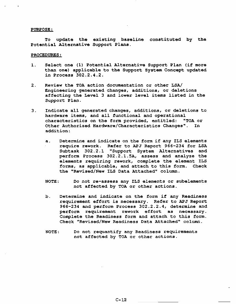
To update the existing baseline constituted by thePotential Alternative Support Plans.
PROCEDURES:
1. Select one (1) Potential Alternative Support Plan (if morethan one) applicable to the Support System Concept updatedin Process 302.2.4.2.
2. Review the TOA action documentation or other LSA/Engineering generated changes, additions, or deletionsaffecting the Level 3 and lower level items listed in theSupport Plan.
3. Indicate all generated changes, additions, or deletions tohardware items, and all functional and operationalcharacteristics on the form provided, entitled: "TOA orOther Authorized Hardware/Characteristics Changes". Inaddition:
a. Determine and indicate on the form if any ILS elementsrequire rework. Refer to APJ Report 966-234 for LSASubtask 302.2.1 "Support System Alternatives andperform Process 302.2.1.5A, assess and analyze theelements requiring rework, complete the element ILSforms, as applicable, and attach to this form. Checkthe "Revised/New ILS Data Attached" column.
NOTE: Do not re-assess any ILS elements or subelementsnot affected by TOA or other actions.
b. Determine and indicate on the form if any Readinessrequirement effort is necessary. Refer to APJ Report966-234 and perform Process 302.2.2.4, determine andperform requirement rework effort as necessary.Complete the Readiness form and attach to this form.Check "Revised/New Readiness Data Attached" column.
NOTE: Do not requantify any Readiness requirementsnot affected by TOA or other actions.
C-.12

REFERENCES:
The following references may be useful:
- LSA 303, Evaluation of Alternatives and Trade-offAnalysis
- AR 70-37, Configuration Management
C-13

mom
040
0l
H aON
0)0
0.C
0 b4
.944
0 c
00 0
IV 0
C- 1

PROCESS 302.2.4.4 - Updated Viable Support Plan Alternatives
PURPOSE:
To establish updated Viable Support Plan Alternatives thatwill satisfy the functional and operational requirements of theSystem/Equipment Alternatives.
PROCEDURES:
1. Review the Updated Readiness forms that resulted incompleting Process 302.2.2.4 and compare the Readinessconstraints with the calculated updated Sub-Subsystem/Sub-Subequipment and lower indenture level hardware Readinessrequirements. Where calculated requitements exceed theestablished threshold level of the system/equipment and itssub-level hardware constraints, will make the viableSupport Concept Alternative and the related PotentialSupport Plan, for the system/equipment under consideration,unacceptable.
2. Each viable Support Plan Alternatives fulfilling thesupport needs of the system/equipment alternative shallhave its documentation assembled and packaged for Trade-OffAnalysis in accordance with LSA Task 303.
C-15

ANNEX D
VERT BATCH INPUT FILESFOR
LSA SUBTASKS 302.2.3 AND 302.2.4

VERT APPLICATION METHODOLOGY
BACKGROUND:
Venture Evaluation and Review Technique (VERT) wasdeveloped as a network analysis technique to facilitatemanagement decision making. It allows a systematic planning andcontrol of programs and enables managers to find solutions toreal life managerial problems.
The terms of the APJ contract require the provision ofbatch files for each of the VERT networks associated with thevarious Data Flow Diagrams in the APJ 966 projects.
APJ has been successful in adopting a method for thecreation of these networks using the existing EXCELERATORsoftware package and establishing a naming convention compatiblewith that used in the Data Flow Diagrams. To do this APJ hasmade use of the PC model of VERT. A Structured Analysis projectwas used for this purpose. The prototype VERT network structurewas made for one top level and one lower level data flowdiagram.
The PC model of VERT has certain limitations built into it.To overcome some of these limitations, certain conventions wereused to create the input files. To maintain full generality aset of "dummy" default values were established. The modelallows the user to alter the default values of time, cost, andperformance to satisfy their specific requirements.
METHODOLOGY:
The basic symbols used to structure the network are
(i) SQUARES - to indicate NODES. These arein the project, or points beyond which the
project cannot proceed unless certain criteria aremet. There are two types of nodes, one which supportsinput operations and, the second type which supportsoutput operations.
(ii) LINMS - to indicate ARCS which are • thathave time, cost, and performance criteria associatedwith them.
In practice, however, both the arcs and nodes are similar,in that both have time, cost, and performance criteriaassociated with them. The arcs have a primary and a cumulativeset of time, cost, and performance criteria whereas the nodeshave only a single cumulative set.
D- I

(iii) NAMING CONVENTIONS - Efforts have been made to keepthe naming convention as compatible as possible tothe Data Flow Diagrams. The naming convention usedis displayed below.
NODES - All nodes are prefixed with the letter N. Theindividual Nodes are identified by a number and aletter. The number refers to the number of the nodewithin the diagram and the letter refers to thediagram number in the project. In the event that anode has been referenced in an earlier diagram theyalso carry the number of the node in the earlierdiagram as a prefix to the individual node number.
N2.4A
N - All nodes are prefixed with the letter N2 - Gives the number of the node it relates to in
a higher level diagram or an earlier data flowdiagram within the project.. In this case itrefers to node N2 of the top level diagram.
4 - Gives the number of the node in the presentdata flow diagram.
A - The nodes in each subsequent explosion arealloted an alphabetical suffix indicating thenumber of the explosion diagram in theparticular project. In this case it is thefirst lower level diagram within the project.
ARCS - All arcs are prefixed with either the letter Cor Z. The individual Arcs are identified by twonumbers. The first number refers to the number of thearc within the diagram and the second number refers tothe number of the diagram within the project. In theevent that an arc has been referenced in an earlierdiagram they also carry the number of the arc in theearlier diagram as a prefix to the individual arcnumber. The arcs which are identified by the letter Zhave direct reference to a process in thecorresponding data flow diagram and as such are namedthe same as the process itself.
C3.3.8.4 E12.1A2
C - All arcs are prefixed with the letter C. Insome cases, however, arcs carry a prefix of Z.These particular arcs correspond to a processwithin the data flow diagram and are thusnamed the same as the process itself.
D-2
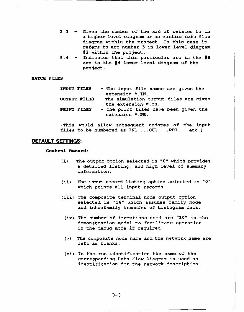
3.3 - Gives the number of the arc it relates to ina higher level diagram or an earlier data flowdiagram within the project. In this case itrefers to arc number 3 in lower level diagram#3 within the project.
8.4 Indicates that this particular arc is the #8arc in the #4 lower level diagram of theproject.
BATCH FILES
INPUT FILES - The input file names are given theextension *.IN.
OUTPUT FILES - The simulation output files are giventhe extension *.OU.
PRINT FILES - The print files have been given theextension *.PR.
(This would allow subsequent updates of the inputfiles to be numbered as INI...,OUI...,PR1... etc.)
DEFAULT SETflNGS:
Control Record:
(i) The output option selected is "0" which providesa detailed listing, and high level of summaryinformation.
(ii) The input record listing option selected is "0"which prints all input records.
(iii) The composite terminal node output optionselected is "16" which assumes family modeand intrafamily transfer of histogram data.
(iv) The number of iterations used are "10" in thedemonstration model to facilitate operationin the debug mode if required.
(v) The composite node name and the network name areleft as blanks.
(vi) In the run identification the name of thecorresponding Data Flow Diagram is used asidentification for the network description.
D-3

Arc Records:
(i) For each of the arcs the following records areprovided:(a) Master Arc Record(b) Time Distribution Satellite(c) Cost Distribution Satellite(d) Performance Distribution Satellite
(ii) The Distribution Satellite Records are created toprovide a uniform statistical distribution.
(iii) The default values used for the minimum andmaximum in each criteria are:
TIME 10.0 20.0COST 10.0 100.0PERFORMANCE 10.0 50.0
Node Records:
(i) Input Logic - The input logic for the nodes areeither "INITIAL" or "AND".
(ii) Output Logic - The output logic has beendefaulted to "AND" or "TERMINAL".
(iii) The output option indicator and the storageoption indicator are defaulted to read "0".
(iv) The node description has also been left blank.
(It is again noted that the user can change thedefault values to desired values as identified by theparticular requirement and applications.)
DOCUMENTATION:
With every project report APJ will be providing thefollowing documents relating to the VERT:
(i) A VERT network diagram corresponding to aparticular data flow diagram.
(ii) A print out of the VERT network inputs for theparticular data flow diagrams.
(iii) A floppy disc containing the sample input,print, and the simulation output files forthe default VERT network.
D-4
101T ~ ~ ~ ~ C .1 ADC.1X
ALL INTIT zDIVIE ALL
33002231
ALTXQP TORO
XMIT C.1 C31 INA
33NC"10223223
ALTRATV ogrnilIOUPTDRN
N7A
303.02 V33
ALT. abaqTd 1SC1
PLAN5

N E W N ETW 0 R K PAGE 11 2 3 4 5 6 7
1234567890123456789012345678901234567890123456789012345678901234567890121. 0016 10r ALTERNATE SUPPORT PLAN UPDATE
+ 4- 4- 4 + +- 4
2. C1.0 N1.0 N3.0 1.0 DEFINE SYSTEM/EQUIPMENT ALTERNATE CONFIGURA3. C1.0 DTIME 1 2 10.0 20.04. C1.0 DCOST 1 2 10.0 100.05. CI.0 DPERF 1 2 10.0 50.0
+ 4 +- 4- 4 + +
6. C2.0 N2.0 N3.0 1.0 DEFINE UNINCORPORATED TOA ACTIONS7. C2.0 DTIME 1 2 10.0 20.08. C2.0 DCOST 1 2 10.0 100.09. C2.0 DPERF 1 2 10.0 50.0
+ 4 4- 4 4 + +
10. E302241 N3.0 N5.0 1.0 SELECT UPDATED SYSTEM/EQUIPMENT FOR ANALYSI11. E302241 DTIME 1 2 10.0 20.012. E302241 DCOST 1 2 10.0 100.013. E302241 DPERF 1 2 10.0 50.0
+ 4- + + 4- 4- 4
14. C4.0 N4.0 N5.0 1.0 DEFINE VIABLE SUPPORT CONCEPT ALTERNATIVES15. C4.0 DTIME 1 2 10.0 20.016. C4.0 DCOST 1 2 10.0 100.017. C4.0 DPERF 1 2 10.0 50.0
4- + +- - 4- 4- 4
18. C5.0 N1.0 N6.0 1.0 DEFINE UNINCORPORATED TOA ACTIONS19. C5.0 DTIME 1 2 10.0 20.020. C5.0 DCOST 1 2 10.0 100.021. C5.0 DPERF 1 2 10.0 50.0
22. C6.0 N2.0 N6.0 1.0 IDENTIFY ENGINEERING CHANGE DOCUMENTS23. C6.0 DTIME 1 2 10.0 20.024. C6.0 DCOST 1 2 10.0 100.025. C6.0 DPERF 1 2 10.0 50.0
26. E302242 N5.0 N6.0 1.0 SELECT UPDATED VIABLE SUPPORT CONCEPT27. E302242 DTIME 1 2 10.0 20.028. E302242 DCOST 1 2 10.0 100.029. E302242 DPERF 1 2 10.0 50.0
- 4- 4- 4 + 4- 4
30. C8.0 N4.0 N7.0 1.0 DEFINE UPDATED QUANTIFIED ILS AND READINESS31. C8.0 DTIME 1 2 10.0 20.032. C8.0 DCOST 1 2 10.0 100.033. C8.0 DPERF 1 2 10.0 50.0
34. E302243 N6.0 N7.0 1.0 DEFINE UPDATED POTENTIAL ALTERNATIVE SUPPOR35. E302243 DTIME 1 2 10.0 20.036. E302243 DCOST 1 2 10.0 100.037. E302243 DPERF 1 2 10.0 50.0
38. E302244 N7.0 N8.0 1.0 DEFINE UPDATED VIABLE ALTERNATIVE SUPPORT P39. E302244 DTIME 1 2 10.0 20.040. E302244 DCOST 1 2 10.0 100.041. E302244 DPERF 1 2 10.0 50.0
+ + + + + + A.
42. ENDARC
43. N1.0 1 2 0 0
1 2 3 4 5 6 7
D-6

123456789012345678901234567890123456789012345678901234567890-123456789012N EW N ET WOR X PAGE 2
1 2 3 4 5 6 712345678901234567890123456789012345678 9012345678 901.234567890 123456789012
44. N3.0 2 2 0 0
45. N2.0 1 2 0 0
46. N45.0 2 2 0 0
47. N44.0 1 2 0 0
48. N6.0 2 20 0
49. N7.0 2 20 0
50. N48.0 2 10 0
5 1. ENDNODE1 2 3 4 5 6 7
123456789012345678901234567890123456789012345678901234567890123456789012i
D-7
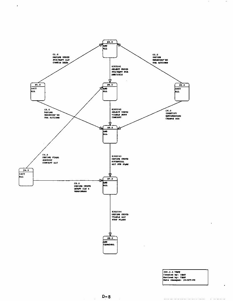
N3. 0
cl. 0 C2. 0Darius vrmw DgrlWgSYS/SQWT ALT MINCOMPIRDCONFIG DATA TOA ACTIONS
9302241SSLBCT vrmSYS/%QPT roaAm"Yolm
W1.0 W$. 0 192.0
MIT MITLL
cS.0 9302242 cd.0Darius SBLZCT 7POIM IVINTIryUNINCOMP, to VZAWA SUTF 9MIN&BRINGTOA ACTIONS .,omzrT CRANUS DOC
W6.0
C4.0Daring VIABL 9302243
SUPPORT Darius UFDTD
Co"cgFT ALT roTINTIA1.ALT SUP P1.104
T4.0in."
r-
C9.0 AM
Darius UVDTO ALL
QORWr ILS GRgAD1998S
2302244Darius MTOVIAML9 A.LTmvp PlAws
AMTSMUNAL
302.2.4 VgRTCc"tod byt CSAVftwised byl CMUDate changedf to-OCT-99
D- 8

N E W N E T W O R K PAGE 11 2 3 4 5 6 7
1234567890123456789012345678901234567890123456789012345678901234567890121. 0016 10 ALTERNATE SUPPORT PLANS
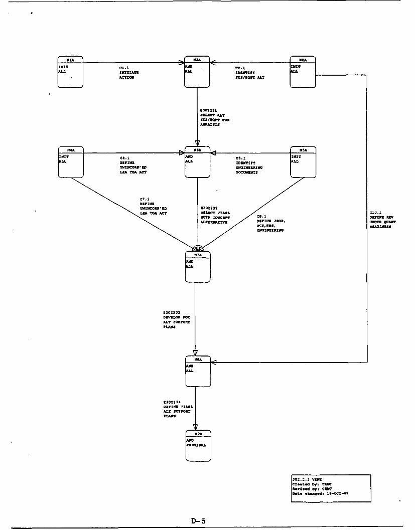
+ + 4- 4 + + .92. C1.1 NIA N3A 1.0 INITIATE ACTION3. C1.1 DTIME 1 2 10.0 20.04. C1.1 DCOST 1 2 10.0 100.05. CL.1 DPERF 1 2 10.0 50.0+ 4- - 4- 4- 4- .
6. C2.1 N2A N3A 1.0 IDENTIFY SYSTEM/EQUIPMENT ALTERNATIVES7. C2.1 DTIME 1 2 10.0 20.08. C2.1 DCOST 1 2 10.0 100.09. C2.1 DPERF 1 2 10.0 50.0
10. E302231 N3A N6A 1.0 SELECT ALTERNATE SYSTEM/EQUIPMENT FOR ANALY11. E302231 DTIME 1 2 10.0 20.012. E302231 DCOST 1 2 10.0 100.013. E302231 DPERF 1 2 10.0 50.0
4- + 4- 4- 4 + 4-14. C4.1 N4A N6A 1.0 DEFINE UNINCORPORATED LSA TOA ACTIONS15. C4.1 DTIME 1 2 10.0 20.016. C4.1 DCOST 1 2 10.0 100.017. C4.1 DPERF 1 2 10.0 50.0
18. C5.1 N5A N6A 1.0 IDENTIFY ENGINEERING DOCUMENTS19. C5.1 DTIME 1 2 10.0 20.020. C5.1 DCOST 1 2 10.0 100.021. C5.1 DPERF 1 2 10.0 50.0
22. E302232 N6A N7A 1.0 SELECT VIABLE SUPPORT CONCEPT ALTERNATIVE23. E302232 DTIME 1 2 10.0 20.024. E302232 DCOST 1 2 10.0 100.025. E302232 DPERF 1 2 10.0 50.0
26. C7.1 N4A N7A 1.0 DEFINE UNINCORPORATED LSA TOA ACTIONS27. C7.1 DTIME 1 2 10.0 20.028. C7.1 DCOST 1 2 10.0 100.029. C7.1 DPERF 1 z 10.0 50.0
30. C8.1 N5A N7A 1.0 DEFINE JSOR,BCS,WBS, ENGINEERING CHANGE DOC31. C8.1 DTIME 1 2 10.0 20.032. C8.1 DCOST 1 2 10.0 100.033. C8.1 DPERF 1 2 10.0 50.0
+ 4- 4- 4- 4- ..34. E302233 N7A NSA 1.0 DEVELOP POTENTIAL ALTERNATE SUPPORT PLANS35. E302233 DTIME 1 2 10.0 20.036. E302233 DCOST 1 2 10.0 100.037. E302233 DPERF 1 2 10.0 50.0
38. C10.1 N2A N8A 1.0 DEFINE REVISED UPDATED QUANTIFIED READINESS39. C10.1 DTIME 1 2 10.0 20.040. C10.1 DCOST 1 2 10.0 100.041. C10.1 DPERF 1 2 10.0 50.0
42. E302234 NSA N9A 1.0 DEFINE VIABLE ALTERNATE SUPPORT PLANS43. E302234 DTIME I 2 10.0 20.044. 3302234 DCOST 1 2 10.0 100.045. E302234 DPERF 1 2 10.0 50.0
D-9

12 3 4 5 6 71234567890123456789012345678901234567890123456 7 8901234567890123456789012
N EW N ET WORKX PAGE 21 2 3 4 5 6 7
12345 678 9012345 678 9012345 678 9012345 678 90 12345 678 9012345 678 9012345678 9012246. ENDARC
47. NlA 1 20 0
48. N3A 2 20 0
49. b*2A 1 2 0 0
50. N6A 2 20 0
51. N4A 1 20 0
52. N5A 1 20 0
53. N7A 2 2 00
54. NSA 2 20 0
55. N9A 2 1 00
56. ENDNODE1 2 3 4 5 6 7
1234567890123456789012345678902.23456789012345678901234567890123456789012
D -10
ANNEX Z
STRUCTURED SYSTEMS ANALYSIS/DESIGN
Fundamentals

ANNEX ESTRUCTURED SYSTEMS ANALYSIS
Fundamentals
Structured Systems Analysis (SSA) has recently become anindustry standard for generating Data Flow Diagrams (replacing"logic diagrams" or "flow charts") to aid in coordinating thefunctions to be performed by a computer program and itsassociated Inputs/Outputs (I/O). During the SSA, each set of"flow charts" can be checked by the potential user to assurethat there is complete agreement on what is to be done by theprogram, and how it is to be accomplished. It also providesconsiderable flexibility for updating or changing the program.
Six basic elements are used in SSA:
1. Process (PRC)2. Data Flow (DAF)3. Data Store (DAS)4. External Entity (EXT)5. Data Flow Diagram (DFD)6. Data Dictionary (DCT)
PROCESS (Represented by a Circle):
A function or operation to be performed which can be explainedby a set of instructions representing a single task, e.g.,"calculate interest on a loan", "prepare a draft report". Ifthe Process description is too complex to describe in a fewsteps, it may be necessary to develop a lower level description(see below).
DATA FLOW (Lines interconnecting Processes or I/Os):
Each function or Process cannot be a stand-alone in a complexnetwork. To have any meaning in a program, each process must beinitiated by a previous action and/or provided information onwhich to act. Furthermore, a Process must result in an outputwhich is the input to the next logical Process. These inputs,outputs, or initiating actions are identified as Data Flows, andare represented by the Data Flow lines indicating its point oforigin and the process to which it provides data.
E-l

DATA STORE (Represented by two parallel lines):
Although some Processes generate data used as input to asucceeding Process, there is often a need to "gather or collect"information from files in which it is stored. This informationmay come from an external source (such as a MIL-STD, Armyregulation, historical experience files, etc.), or an internalsource or file in which data is temporarily stored for use bysucceeding processes. These Data Stores can be visualized as a"file cabinet", in which the data are stored for laterretrieval).
EXTERNAL ENTITY (Represented by a Rectangle):
Each program or logical process must have an initiatingaction, a "point" of disposition of the results, and possibleinput guidance or instructions. Each of these have authorities,functions, or applications which are independent of the programProcess (although required by the program Process) . Thus, theseactivities, agencies, or facilities are considered "ExternalEntities" to the program.
DATA FLOW DIAGRAM:
The general arrangement of the above can be readily seen.First, the circle or Process describes what has to be done; theinterconnecting lines represent the Data Flows, together withthe specific description of all I/Os. The Data Stores identifythe source and/or file designation of a data base, and theExternal Entities represent those activities remote from theProcess, which are the source of guidance or the recipients ofthe program. This combination of Processes, Data Flows, DataStores, and External Entities constitutes a "Data FlowDiagram". The unique feature of the Data Flow Diagram (DFD) isthat each process can be considered independently, permitting achange to be made in one Process without a major change in theoverall program.
DATA DICTIONARY:
The Data Dictionary consists of a complete description of eachof the basic elements. For the Process, it contains astep-by-step description of what has to be performed. Thedescription of the Data Flow identifies the nomenclature of thedata, a detailed description of its content, and its source.The Data Stores and External Entities are described, includingpossible location.
E-2
The Data Dictionary (a living document) begins with adescription of the first Process and is continually built-up asthe Data Flow Diagrams are expanded, detailed, and eventuallycompleted.
APPROACH TO PERFORMING STRUCTURED SYSTEM ANALYSIS:
The best approach to Structured Systems Analysis is to assumethat the program consists of a series of processes, each ofwhich are to be assigned to an inexperienced analyst. Eachanalyst is to be walked through the assigned process of theProgram, explaining step-by-stepwhat functions have to beperformed or what actions have to be taken to accomplish theprocess. The analyst is also informed where the information iscoming from (input Data Flow), what is to be generated by eachprocess (output Data Flow), where the data base may to be found(Data Stores), and who to contact for guidance (ExternalEntities).
The best way to initiate a SSA is to set down the point oforigin of a program, its final goal(s), and the intermediatefunctions or actions needed to get from beginning to goal. Eachstep should be considered as a Process - some may be sequentialand others parallel. Then, the steps needed to accomplish theProcess should be described. If the description is complex andneeds intermediate steps, the Process is then a candidate for an"explosion". That is, the top (or upper) level Process isconsidered as a "project" and its own Data Flow Diagram isprepared.
When writing the step-by-step procedures in the Process,certain elements of data (or information) must be made availablefor the procedure. Each element of data is considered as aninput Data Flow, which is identified and described. Theproduct (or result) of a Process is an output Data Flow element.
Each Data Flow to the Process must originate from:
1. an earlier Process2. a Data Store (or file)3. an External Entity.
These sources are also identified, described and put into theData Dictionary. As soon as the last portion of the Data FlowDiagram has been described, the SSA is complete.
E-3

SURVEYOF PROBLEM
Structured DEFINIT IONS/EVALUATIONSjAnalysis
DATA FLOW DIAGRAMSDATA DICTIONARY INITIATION
Inte ace REVIEW/CRITIQUE/ACCEPTANCE OF DFD
StructuredSystemsDesign DATA DICTIONARY STRUCTURED ENGLISH
EXPANSION DATA STRUCTURE DIAGRAM
PROGRAM
ETEST
Figure 1. Structured Analysis & StructuredSystems Design Organization
E-4

REPRESENTS A PROCESS, FUNCTIONOR ACTION
REPRESENTS A DATA STORE OR ADATA FILE - OFTEN IDENTIFIED ASA REPOSITORY OF INFORMATION OFA SPECIFIC TYPE
REPRESENTS A DATA ELEMENTFLOW INDICATING OUTPUT FROMONE PROCESS AND INPUT TOANOTHER PROCESS
REPRESENTS AN EXTERNALENTITY - AN ACTIVITY NOT APART OF THE SYSTEM/PROCESSBEING MODELED.
Figure 2. Standard DFD Symbol Definitions
E-5


![[XLS] · Web view1 302 2 302 3 302 4 302 5 302 6 363 7 363 8 302 9 302 10 307 11 302 12 302 13 223244 14 302 15 302 16 224 17 302 18 302 19 302 20 302 21 302 22 23 24 25 26 302 27](https://static.fdocuments.in/doc/165x107/5b00c3a37f8b9a952f8d6104/xls-view1-302-2-302-3-302-4-302-5-302-6-363-7-363-8-302-9-302-10-307-11-302-12.jpg)