Structured, Active, In-Class Learning: Connecting the ... · Background Structured, active, in...
12
Paper ID #12384 Structured, Active, In-Class Learning: Connecting the Physical to the Math- ematical in an Introductory Biomechanics Course (Work in Progress) Dr. LeAnn Dourte Segan, University of Pennsylvania Dr. LeAnn Dourte Segan is a lecturer at the University of Pennsylvania in Philadelphia, PA. Her primary teaching focus is in the field of solid biomechanics at the undergraduate and graduate levels. Sarah Ilkhanipour Rooney, University of Pennsylvania Sarah I. Rooney is a Ph.D. candidate in the Bioengineering department at the University of Pennsylvania. She received her B.S.E. (2009) and M.S.E. (2010) in Biomedical Engineering from the University of Michigan (Ann Arbor). c American Society for Engineering Education, 2015 Page 26.1408.1
Transcript of Structured, Active, In-Class Learning: Connecting the ... · Background Structured, active, in...

Paper ID #12384
Structured, Active, In-Class Learning: Connecting the Physical to the Math-ematical in an Introductory Biomechanics Course (Work in Progress)
Dr. LeAnn Dourte Segan, University of Pennsylvania
Dr. LeAnn Dourte Segan is a lecturer at the University of Pennsylvania in Philadelphia, PA. Her primaryteaching focus is in the field of solid biomechanics at the undergraduate and graduate levels.
Sarah Ilkhanipour Rooney, University of Pennsylvania
Sarah I. Rooney is a Ph.D. candidate in the Bioengineering department at the University of Pennsylvania.She received her B.S.E. (2009) and M.S.E. (2010) in Biomedical Engineering from the University ofMichigan (Ann Arbor).
c©American Society for Engineering Education, 2015
Page 26.1408.1

Structured, Active, In-Class Learning: Connecting the Physical to
the Mathematical in an Introductory Biomechanics Course (Work
in Progress)
Introduction
Introduction to Biomechanics is a required sophomore course in the Bioengineering curriculum
at the University of Pennsylvania focusing on the application of statics and mechanics to biologic
systems. To be successful, students must have an understanding of both mathematical and
applicable physical/biologic constraints. While mechanics of materials is traditionally taught
from an instructor-led, problem solving approach, a complete understanding of the material
covered in a biomechanics course should also include a conceptual component which is
constrained by the physical world and human biology. Over the past three years of this
Introduction to Biomechanics course, it has been observed that students excel at problem solving
when the problem resembles an example they have encountered before, but often struggle
adapting their problem-solving process when presented with a novel or more complex scenario.
Additionally, students struggle to explain the physical meaning of the mathematical formula and
have difficulty approximating solutions within the physical bounds.
Previous studies have demonstrated that student-centered, active, inductive learning activities
can enhance problem-solving abilities, improve academic achievement and create more positive
attitudes toward learning.1-3
There is particular interest in incorporating active learning principles
into this course because of the dual need to understand both physical concepts and complex
mathematics. Historically, the course met twice a week for passive, instructor-led lectures with
weekly, small-group, TA-supervised problem solving recitations. Given the previously
mentioned student challenges, the course with an enrollment of 58 students was redesigned for
the Fall 2014 semester to incorporate active learning principles, with an emphasis on problem
scaffolding and connecting mathematical concepts to physical reality. This paper presents a work
in progress of the modified course. The course was developed with the following goals which
were hypothesized to produce better outcomes using a structured active learning environment.
1. Students should develop a problem-solving framework flexible enough to accommodate
new problems and deviations from examples, while still understanding the concepts well
enough to effectively communicate their thought process, including explicitly stating the
limitations associated with their answers and communicating these assumptions verbally
and numerically.
2. Students should gain physical insight into the mathematical equations and develop a
contextual instinct for the solution (e.g., magnitude of an answer, tension or compression)
Specifically, we utilized in-class, collaborative group problem solving activities, hands-on,
guided “discovery labs” and an instant feedback clicker system.
Page 26.1408.2

Background
Structured, active, in-class learning (SAIL) is a term used to describe classroom education with
an emphasis on learning-by-doing.2 Class time is built around a variety of activities with clear
educational goals meant to engage students in the learning process. These may include group
problem solving, interpreting data or evidence, or engaging in practices of the field, such as
justifying simplifications or estimating magnitude of an answer.
One specific type of SAIL activity is small-group, in-class solving of a problem based on real-
world applications. Students work in small groups to accomplish a common learning goal and
are encouraged to use the problem solving process of experienced decision makers: define the
situation, state the goal, generate ideas, prepare a plan, take action and check to see if the goal
was achieved.4 This type of collaborative learning activity has been shown to positively engage
students in the classroom and emphasize the process of solving a problem, not just the end-goal
of obtaining a solution.2,5,6
Even though the work is done in groups, individual performance,
attitudes and retention have all been shown to increase with collaborative instructional
methods.3,7,8
This technique also provides a support system for struggling students and develops
collaborative teamwork skills necessary for success in the engineering field.5,6
Another type of SAIL activity is guided, discovery based learning. Students are encouraged to
interact with objects, notice patterns and ultimately discover information within the provided
materials, but without explicit, instructor-led instruction.9,10
Debate continues as to the
limitations of unassisted discovery based learning; however, guided or enhanced discovery has
been shown to lead to greater learning than explicit instruction.9 Cooperative, hands-on activities
designed to serve as “discovery labs” can be used as a means to lead students from a physical
description of mechanics to a mathematical description. These kinesthetic/tactile activities can be
directly connected to deeper thinking about the how and why of the results.11,12
This type of
activity reflects a fundamental aspect of the engineering modeling process where an engineer
observes a physical phenomenon, e.g. mechanical behavior of a material, and develops ways to
quantify the behavior to use in a predictive manner in the future.
The scope of this paper focuses on the development, implementation and planned assessment of
SAIL techniques in a Biomechanics course to address our goals and is a work in progress. We
dedicated 50% of class time to group problem solving sessions and physical, hands-on activities,
and 50% to lectures supplemented with discussion and short feedback questions.
Implementation
To improve students’ problem solving abilities, the class was divided into groups of three with
each member assigned a specific role (Appendix A). Both groups and roles rotated throughout
Page 26.1408.3

the semester. For the group problem solving sessions, a biologically motivated mechanics
problem with a design and/or estimation component was distributed to each group. The
fundamental mechanics concepts needed to solve the problem were presented in class in the
preceding lectures and now students were asked to analyze the problem within the context of the
information they had already learned. A problem-solving outline was also provided and began
with an estimation of the expected answer and/or a question about simplifying the given
information into a solvable statics or mechanics problem to reinforce the course goals.
Additional steps required groups to express their equations symbolically before plugging in
numbers, identify assumptions and limitations of their methods, and evaluate the practicality of
their final answer. Outlines contained more detailed guidance in the beginning of the semester
(see Appendix B) and became less detailed as the semester progressed. Students were
encouraged to discuss and develop conclusions together and to ensure all members of the group
were confident in the steps before moving forward. During the problem solving sessions, two
faculty members and two graduate TAs circulated throughout the room to help answer questions.
To aid in gauging class progress, groups had access to a flag system (e.g. green, yellow and red
flags in a block on the table). This method helped identify if there was a particularly difficult step
which the class as a whole needed to regroup and clarify or if students were progressing rapidly
through the material and future problems should be made more challenging. Solutions to the
problems were posted online after class, and assignments were graded with emphasis on the
problem solving process instead of the final answer.
Hands-on activities introduced concepts that the students had not previously studied. Rather than
presenting the mathematical derivation as the introduction to a topic, students were again divided
into groups and given materials and actions to impose on these materials, e.g. loading in bending.
A provided outline for these “discovery labs” aimed to help the students to first observe and
describe a physical phenomenon and then describe it mathematically. For example, this past
semester we had students build different types of supports out of wood, screws and string to
represent different joints in the body, i.e. the elbow as a hinge between two pieces of wood. They
were then asked how these joints resisted translational and rotational motion – the physical
corollary to reactions in mechanics. Other hands-on activities included deriving the quantities of
stress and strain using elastic and a spring scale (see Appendix C), observing shear strains under
torsional loading in a foam pool noodle and exploring beam bending with a piece of Neoprene.
In order to transition these activities into the course, some of the traditional lecture material was
moved outside of class time. Three video lectures were created to follow some of the hands-on
activities for online, post-class viewing. These lectures were limited to a maximum of 15 minutes
and focused on connecting the hands-on activity performed by the students to the mathematical
description of the phenomena. In order to encourage students to take an active role in their own
learning and to ensure students were participating in the out-of-class material, we also instituted
short, online comprehension quizzes to be completed after viewing the videos for a minimal
Page 26.1408.4

portion of the final grade. Material that had previously been identified as problematic for
introductory students remained in lecture format punctuated by interactive questions. To engage
the class, Learning Catalytics, an instant feedback system where answers are recorded using a
student’s laptop, tablet or smartphone, was utilized. Questions ranged from stating a basic
concept to computing a mathematical answer for a simplified problem.
Assessment
Three exams were administered during the semester and incorporated “big-picture” concept
questions in addition to traditional, numerical mechanics problems. Throughout the semester,
instant feedback “clicker questions” in multiple choice or short answer format were utilized to
review material, assess student understanding and prepare for the concept questions on the
exams. Because exam solutions are released each year, matched exam questions with previous,
non-SAIL formatted years are not feasible. However, the topic(s) and goal for each problem
along with the average problem score will be tabulated and compared across years to identify if
any patterns exist.
A variety of non-exam assessments were also administered in collaboration with the University’s
Center for Teaching and Learning. A concept inventory quiz was administered at the beginning
and end of the semester based on previously published question inventories.13,14
The questions
included concepts that should have been recalled from prerequisite courses as well as material
that would be learned throughout the course of the semester. These same concept inventories
were administered the year before in the non-SAIL formatted course and will be compared to the
SAIL formatted course. The concept inventories will be evaluated for increases in new
knowledge (beginning to end of the semester) but also for trends in solidifying fundamental
physics concepts that may have been forgotten coming into the semester.
Additional evaluation will be conducted using a pre-, mid- and post-semester survey distributed
using the online survey system Qualtrics. Once compiled, this software will allow for correlation
between student comments, ratings, confidence in their abilities, preparation for class and global
trends associated with final grades in the course blinded to the instructors. The survey will also
evaluate if previous exposure to a SAIL formatted course influences student expectations. Since
SAIL freshman course offerings are becoming more common at our University, we plan on
continuing to evaluate the results in the years ahead.
Summary
Moving forward, the assessment data associated with the Fall 2014 semester will be analyzed
and faculty impressions recorded before deciding which aspects of the course were most
successful. Preliminary qualitative feedback suggests that while students were initially wary of
Page 26.1408.5

the new format, as the course progressed they found the activities beneficial. Students often
reflected on how much they liked the support of their peers in group sessions and how it was
encouraging to know that there were others struggling with difficult concepts. Initial faculty
impressions are that the SAIL activities deepened student understanding and while there is
always room for improvement, the general concepts will be reused in future iterations of the
course.
Acknowledgements
The authors wish to thank Dr. David Meaney for his help in implementing this course. The
authors acknowledge support for this work through a grant to the University of Pennsylvania as a
project site for the AAU Undergraduate STEM Education Initiative.
References
1. Hake RR. Interactive-Engagement versus Traditional Methods: A Six-Thousand-Student Survey of Mechanics
Test Data for Introductory Physics Courses. American Journal of Physics. 1998; 66(1):64-74.
2. Prince M. Does Active Learning Work? A Review of the Research. Journal of Engineering Education. 2004;
93(3):223-231.
3. Springer L, Stanne ME, Donovan SS. Effects of Small-Group Learning on Undergraduates in Science,
Mathematics, Engineering, and Technology: A Meta-Analysis. Review of Educational Research. 1999;
69(1):21-51.
4. Wales CE, Stager RA. Thinking with Equations: Problem Solving in Math & Science. Morgantown, West
Virginia: C.E. Wales; 1990.
5. National Research Council. Educating the Engineer of 2020: Adapting Engineering Education to the New
Century. Washington, DC: The National Academies Press; 2005.
6. Duderstadt JJ. Engineering for a Changing World: A Roadmap to the Future of American Engineering Practice,
Research, and Education. In: Domenico G, Burkins MB, eds. Holistic Engineering Education: Beyond
Technology. New York: Springer; 2010: 17-35.
7. Johnson D, Johnson R, Smith K. Cooperative Leraning Returns to College: What Evidence is there that it
Works? Change. 1998; 30(4):26-35.
8. Bowen CW. A Quantitative Literature Review of Cooperative Learning Effects on High School and College
Chemistry Achievement. Journal of Chemical Education. 2000; 77(1):116.
9. Alfieri L, Brooks PJ, Aldrich NJ, Tenenbaum HR. Does Discovery-Based Instruction Enhance Learning?
Journal of Educational Psychology. 2011; 103(1):1-18.
10. Felder RM, Brent R. The ABC's of engineering education: ABET, bloom's taxonomy, cooperative learning, and
so on. Proceedings of the 2004 American Society for Engineering Education Conference and Exposition, Salt
Lake City, UT. 2004.
11. Fleming ND. VARK—A guide to learning styles. www.vark-learn.com. 2002.
12. Felder RM, Silverman LK. Learning and Teaching Styles in Engineering Education. Engineering education.
1988; 78(7):674-681.
13. Hestenes D, Wells M, Swackhamer G. Force Concept Inventory. The Physics Teacher. 1992; 30:141-158.
14. Richardson J, Morgan J, Evans D. Development of an engineering strength of material concept inventory
assessment instrument. Proceedings of the 33rd
ASEE/IEEE Frontiers in Education Conference, Boulder, CO.
2003.
Page 26.1408.6
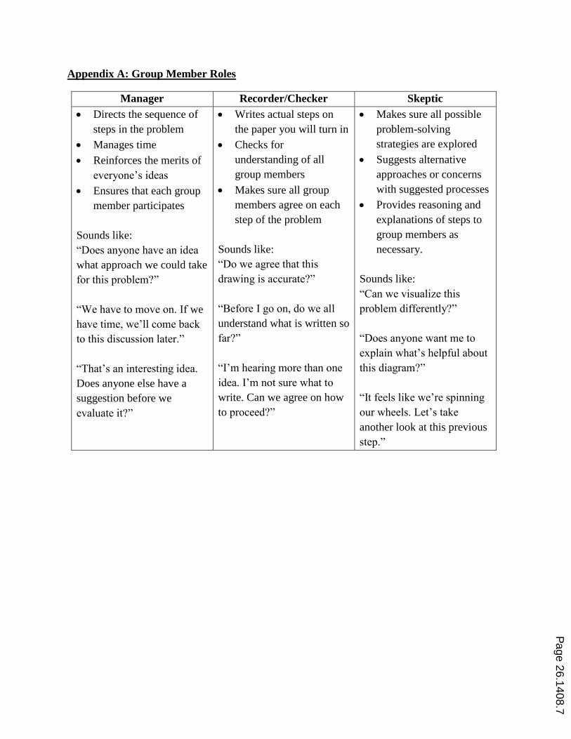
Appendix A: Group Member Roles
Manager Recorder/Checker Skeptic
Directs the sequence of
steps in the problem
Manages time
Reinforces the merits of
everyone’s ideas
Ensures that each group
member participates
Sounds like:
“Does anyone have an idea
what approach we could take
for this problem?”
“We have to move on. If we
have time, we’ll come back
to this discussion later.”
“That’s an interesting idea.
Does anyone else have a
suggestion before we
evaluate it?”
Writes actual steps on
the paper you will turn in
Checks for
understanding of all
group members
Makes sure all group
members agree on each
step of the problem
Sounds like:
“Do we agree that this
drawing is accurate?”
“Before I go on, do we all
understand what is written so
far?”
“I’m hearing more than one
idea. I’m not sure what to
write. Can we agree on how
to proceed?”
Makes sure all possible
problem-solving
strategies are explored
Suggests alternative
approaches or concerns
with suggested processes
Provides reasoning and
explanations of steps to
group members as
necessary.
Sounds like:
“Can we visualize this
problem differently?”
“Does anyone want me to
explain what’s helpful about
this diagram?”
“It feels like we’re spinning
our wheels. Let’s take
another look at this previous
step.”
Page 26.1408.7
Appendix B: Sample Group Problem and Provided Outline: Higher level of detail as
presented in the beginning of the semester
Name (printed) Name (signed)
Manager: _______________________ _______________________
Recorder/Checker: _______________________ _______________________
Skeptic: _______________________ _______________________
IN-CLASS GROUP PROBLEMS: MUSCULOSKELETAL ANATOMY AND STATICS
To be completed during class. Please pay particular attention to the recommended times for each
section and contact an instructor if your group is significantly surpassing these time
recommendations.
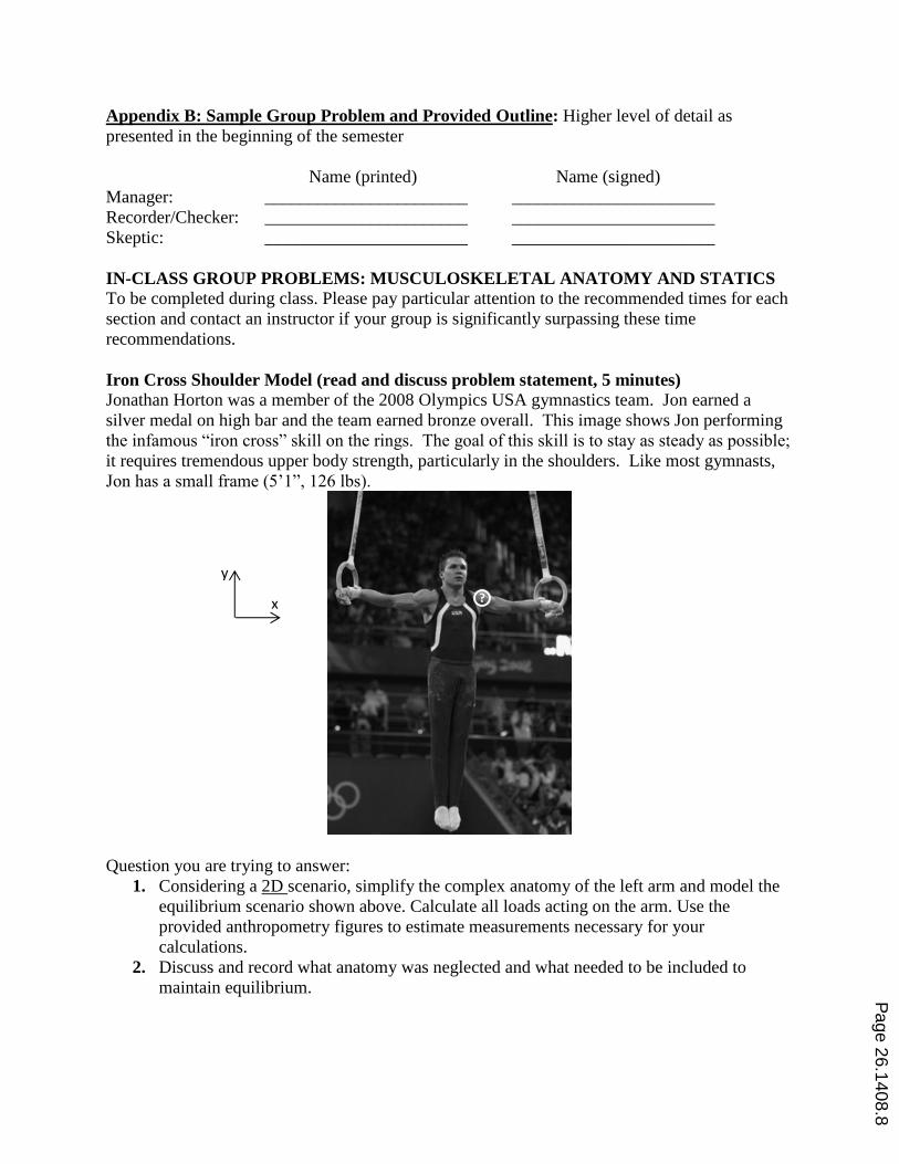
Iron Cross Shoulder Model (read and discuss problem statement, 5 minutes)
Jonathan Horton was a member of the 2008 Olympics USA gymnastics team. Jon earned a
silver medal on high bar and the team earned bronze overall. This image shows Jon performing
the infamous “iron cross” skill on the rings. The goal of this skill is to stay as steady as possible;
it requires tremendous upper body strength, particularly in the shoulders. Like most gymnasts,
Jon has a small frame (5’1”, 126 lbs).
Question you are trying to answer:
1. Considering a 2D scenario, simplify the complex anatomy of the left arm and model the
equilibrium scenario shown above. Calculate all loads acting on the arm. Use the
provided anthropometry figures to estimate measurements necessary for your
calculations.
2. Discuss and record what anatomy was neglected and what needed to be included to
maintain equilibrium.
x
y
Page 26.1408.8

I. Estimate (5 minutes)
Does your shoulder joint resist translational motion in the xy plane? Does it resist rotational
motion within the xy plane (be clear which axis this is about)? Record your observations.
What reactions will be involved at the shoulder?
II. Focus the Problem (5 minutes)
Draw all appropriate FBD(s) to determine all loads acting on the arm.
Don’t even look at the anthropometry data yet, just label the distances as variables and
assume you’ll be able to find them.
(Hint: what FBD must you draw before drawing the FBD of the shoulder?)
Outline the approach to be taken. Be specific.
III. Describe the Mechanics (15 minutes)
Identify and record the knowns and unknowns.
State which mechanics principles/equations you can use. How many equations is this?
Specifically consider rotational equilibrium, ∑𝑀 = 0
With your current FBD of the arm, will it be satisfied? Justify.
If you answered yes, discuss with your group conceptually what is physically maintaining
equilibrium when you sum moments at the shoulder. Record your answer.
If you answered no, discuss with your group what you need to add to your model. Be
specific (with words) if you are modeling an applied moment (something created by a
force on your FBD) or a reaction moment (resistance to rotation provided by a support).
Record your answer. Include your conclusions on your FBD.
IV. Do the Math (10 minutes)
Translate your mechanics descriptions into equations with variables.
Combine these equations to get the equation(s) for your target variable(s) (don’t substitute in
your numbers yet!).
V. Put in the Numbers (15 minutes)
Put real numbers into your equations and determine numerical values.
VI. Evaluate the Answer (10 minutes)
Are the units correct?
Is the answer unreasonable? Justify.
VII. Answer the Questions (10 minutes)
1. Considering a 2D scenario, simplify the complex anatomy of the left arm and model the
equilibrium scenario shown above. Calculate all loads acting on the arm.
Double check that your work above answers these questions.
2. Discuss what anatomy was neglected and what needed to be included to maintain
equilibrium.
Double check that these assumptions have been appropriately discussed above or
restate here as needed.
Use your own arm and knowledge of arm anatomy to discuss what may have been
neglected.
Page 26.1408.9

Appendix C: Sample Hands-On Discovery Lab: Students were provided with elastic
measuring 5, 10, 15 and 20 cm in length each with a safety pin through each end as well as three
pieces 10cm long pinned together at their ends.
Name (printed) Name (signed)
Manager: _______________________ _______________________
Recorder/Checker: _______________________ _______________________
Skeptic: _______________________ _______________________
HANDS-ON ACTIVITY: STRESS-STRAIN
Goals
1) Understand why stress and strain are important engineering calculations
2) Deduce the strain equation
3) Deduce the stress equation
Materials
Elastic Ruler
Spring scale Safety pins
Background
So far, we have been doing rigid body mechanics; however, we know that in reality, all
materials undergo some finite amount of deformation when loaded. Now, we will learn
about deformable bodies and mechanics of materials.
The length of an unloaded material is known as the original or “gauge” length, Lo. Your
gauge length is between the applied loads exerted by the safety pins.
The term “load” can mean an applied force or moment. If you are talking about
deformation along an axis, the “load” is a force.
Reminder: To reduce error, repeated measurements are needed
At the end of this hands-on activity, you should be able to 1) understand how material
geometry may play an important role in mechanics and 2) write the equations for stress
and strain.
PART 1: STRAIN (30 minutes allotted)
“Strain” is an engineering term used to describe how much a material deforms. Using the
materials in front of you, explore how the length of the material influences the amount of axial
deformation when a load is applied. You will develop a relationship between length and
deformation.
1. In front of you, you will find 4 pieces of elastic cut to different gauge lengths. Apply 2N
of load to each piece of elastic and measure the corresponding deformation. The length
of the material should be measured from the pins. Record your findings in a table. Note
any sources of error in your measurements.
Page 26.1408.10

2. Using the provided graph paper or your computer, create a graph that demonstrates the
relationship between the deformation of the elastic (change in length, ΔL, y-axis) and the
gauge length (Lo, x-axis). Determine the linear relationship.
3. Fact: All of these materials underwent the same amount of strain. The symbol for
strain is ε. Using your graph, discuss what this must mean and use your observations to
write the equation for strain in terms of ΔL and Lo. How much strain did your specimens
undergo?
4. What are the units of strain?
5. For the same strain as this experiment, use your equation to predict the axial deformation
of a piece of elastic that is the length around the equator of the earth (40075 km). What is
the total length of the stretched elastic?
Record answers to all the above questions to turn in. Raise your green flag when you are
finished and begin Part 2. When the entire class has completed Part 1, we will momentarily
pause to discuss your results as a class.
PART 2: STRESS (20 minutes allotted)
“Stress” is an engineering term used to describe the load a material experiences when it is
deformed. Using the materials in front of you, you will explore how the cross-sectional area of
the material influences the amount of load that can be applied to achieve the same deformation.
You will develop a relationship between area and load.
1. In front of you, you will find 3 pieces of elastic that are the same gauge length safety-
pinned together. What is the cross-sectional area of your material? Given the small
thickness of your elastic and the limited resolution of your ruler, what can you do to
increase the thickness dimension to reduce error in your measurement? Determine the
amount of load required to deform the material by 1 cm. Record your findings in a table.
Note any sources of error in your measurements.
2. Now, without changing the gauge length of the material, remove one piece of elastic.
What is the new cross-sectional area of your material? Determine the amount of load
required to deform the material by 1 cm. Add your findings to your table.
3. Finally, repeat the above steps with a single piece of elastic. What is the cross-sectional
area? What is the load required to deform the material by 1 cm? Add your findings to
your table.
4. Using the provided graph paper or your computer, create a graph that demonstrates the
relationship between the cross-sectional area of the elastic (x-axis) and the load required
to achieve the same change in length (y-axis). Determine the linear relationship.
5. Fact: All of these samples experienced the same amount of stress. The symbol for
stress is σ. Using your graph, discuss what this must mean and use your observations to
write the equation for stress. How much stress did your specimens experience?
6. What are the units of stress?
Page 26.1408.11

7. Using your equation, predict the load required to deform 1 cm a piece of elastic the same
length as you tested in this section of the assignment with the same cross-sectional area
as the earth (~1.275 x 10¹⁴
m2).
Please put all supplies back in the bag. Record answers to all the above questions to turn in.
Raise your green flag when you are finished and begin Part 3.
PART 3: SUMMARY QUESTIONS (15 minutes allotted)
1. In part 2, were your 3 samples experiencing the same amount of strain? Explain.
2. In part 1, were your 4 samples experiencing the same amount of stress? Explain.
3. You know from experience and physics that load and deformation are related, often
linearly as in the case of a linear spring. The term relating force and deformation is called
stiffness, k. Recall Hooke’s Law: 𝐹 = 𝑘 ∗ ∆𝐿. A similar relationship between stress and
strain exists, and when linear, is called the Modulus of Elasticity, E. 𝜎 = 𝐸 ∗ 𝜀.
a. Consider a piece of steel and a piece of elastic with the same amount of load
applied to each. Using what you know about the difference between steel and
elastic, describe in relative terms (not numbers) what the geometry of these two
materials must be to experience the same amount of strain under the same
amount of load.
b. Describe the relative geometry of the two materials when they experience the
same amount of stress as they are undergoing the same amount of
deformation.
4. Explain why stress and strain are important engineering concepts in addition to load and
deformation. To aid in your discussion, consider describing to a fellow engineer the
failure stress, failure strain, failure load and failure deformation of a specific piece of hair
(geometry known) versus hair in general.
Record answers to all the above questions to turn in.
Page 26.1408.12