Structure, Properties and Processing of Plastics and...
50
Structure, Properties and Processing of Plastics and Reinforced Plastics (Chap10 in Kalpakjian and Schmid)
Transcript of Structure, Properties and Processing of Plastics and...
Structure, Properties and Processing of �
Plastics and Reinforced Plastics
(Chap10 in Kalpakjian and Schmid)
Objectives
• Thermoplastics, thermosets, elastomers, and reinforced plastics Structure
Property
Applications
Processing
Introduction
• Plastics ~ polymers
• Plastics are engineered materials Large molecules composed of smaller molecules
Made from natural or synthetic resins and compounds
Low density, low tooling costs, good corrosion resistance, low cost
Can be molded, extruded, cast, or used for coatings
Plastics are very versatile materials and are used more than steel, aluminum, and copper combined in the United States
Used as food and beverage containers, packaging, signs, housewares, foams, paints, toys, etc
An important group: reinforced plastics (composites)
Molecular Structure of Polymers
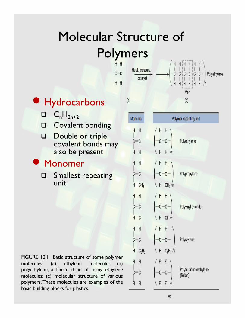
• Hydrocarbons CnH2n+2 Covalent bonding Double or triple
covalent bonds may also be present • Monomer
Smallest repeating unit
FIGURE 10.1 Basic structure of some polymer molecules: (a) ethylene molecule; (b) polyethylene, a linear chain of many ethylene molecules; (c) molecular structure of various polymers. These molecules are examples of the basic building blocks for plastics.

Characteristics of Polymers
• Molecular weight Sum of the molecular weight of the mers in polymer chain
• Bonding Primary bonds: covalent
Secondary bonds: van der Waals , hydrogen bonds, ionic bonds…
• Arrangement of the polymer chains Linear polymer
Branched polymer
Cross-linked polymer (thermosets) and network polymers (3 active covalent bonds)
Effect of Molecular Weight
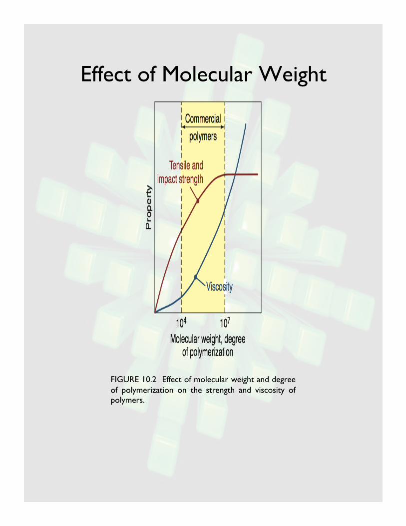
FIGURE 10.2 Effect of molecular weight and degree of polymerization on the strength and viscosity of polymers.

Arrangement of Polymer Chains
FIGURE 10.3 Schematic illustration of polymer chains. (a) Linear structure; thermoplastics such as acrylics, nylons, polyethylene, and polyvinyl chloride have linear structures. (b) Branched structure, such as polyethylene. (c) Cross-linked structure; many rubbers and elastomers have this structure. Vulcanization of rubber produces this structure. (d) Network structure, which is basically highly cross-linked; examples include thermosetting plastics such as epoxies and phenolics.

Crystallinity
• Polymer can be partially crystalline
• Orderly arrangement of molecules in crystalline region (crystallite)
• The higher the crystallinity, the harder, stiffer, and less ductile the polymer
• Can never be 100% crystalline
• Linear polymer is easier to crystallize than branched
• Color:
• Opaque for crystalline
• Transparent for amorphous
FIGURE 10.5 Amorphous and crystalline regions in a polymer.
Effect of Temperature, Crystallinity, Crosslinking
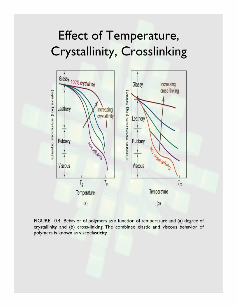
FIGURE 10.4 Behavior of polymers as a function of temperature and (a) degree of crystallinity and (b) cross-linking. The combined elastic and viscous behavior of polymers is known as viscoelasticity.
Glass-Transition Temperature
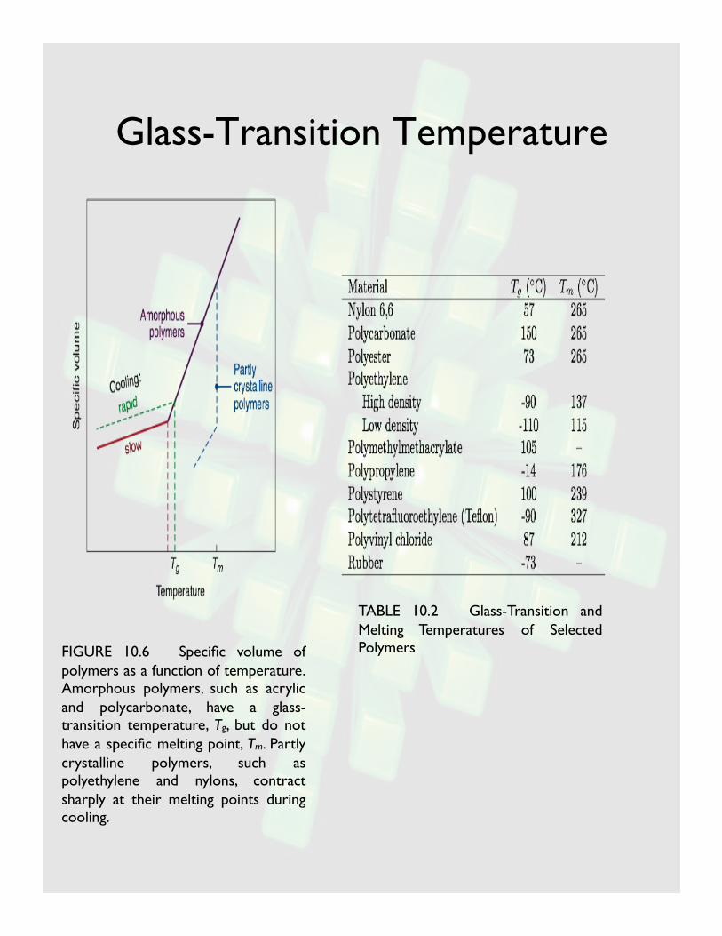
FIGURE 10.6 Specific volume of polymers as a function of temperature. Amorphous polymers, such as acrylic and polycarbonate, have a glass-transition temperature, Tg, but do not have a specific melting point, Tm. Partly crystalline polymers, such as polyethylene and nylons, contract sharply at their melting points during cooling.
TABLE 10.2 Glass-Transition and Melting Temperatures of Selected Polymers
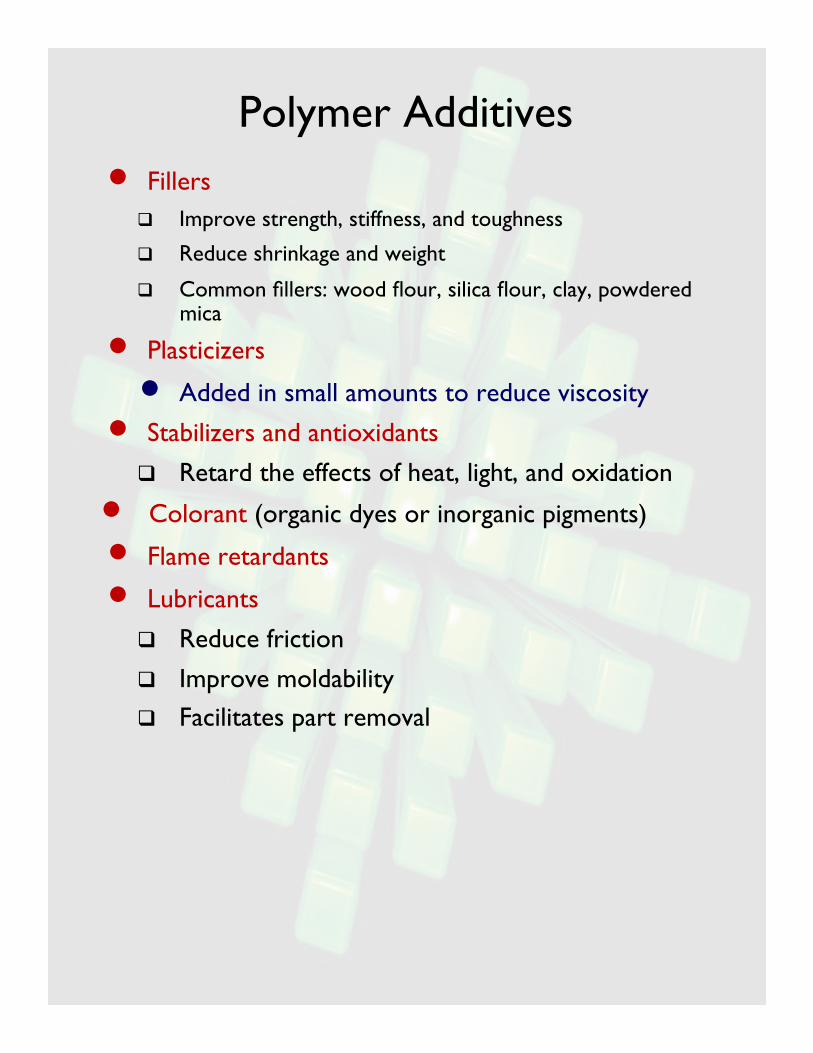
Polymer Additives • Fillers
Improve strength, stiffness, and toughness
Reduce shrinkage and weight
Common fillers: wood flour, silica flour, clay, powdered mica
• Plasticizers
• Added in small amounts to reduce viscosity
• Stabilizers and antioxidants
Retard the effects of heat, light, and oxidation
• Colorant (organic dyes or inorganic pigments)
• Flame retardants
• Lubricants
Reduce friction
Improve moldability
Facilitates part removal

Thermoplastics and Thermosets
• Thermoplastics and thermosets are classified based on their response to heat Internal bonding is covalent (primary)
Intermolecular bonds are van der Waal forces (secondary)
Secondary bond is much weaker than primary
Secondary bonds determine the overall strength of polymers
Heat treatment for thermoplastics is reversible, for thermosets irreversible

Thermoplastics
• Contain molecules of different lengths
• Above the melting temperature, the material can be poured and cast or molded; once cooled, returns to original strength and harness (reversible)
• Application of a force deforms the material both elastically and plastically Plastic deformation occurs by adjacent
chains slipping past one another
• Common thermoplastics Polyethylene (PE)
Polypropylene (PP)
Polystyrene (PS)
Polyvinyl Chloride (PVC)

Thermosets
• Highly cross-linked
• Three-dimensional framework connected by covalent bonds (one giant molecule)
• Typically produced by condensation polymerization Elevated temperatures produce an
irreversible reaction
Once set, subsequent heating will not soften the material
At substantially high temperature, burns up, degrade or char

Properties of Thermosets
• Significantly stronger and more rigid than thermoplastics • Able to resist higher temperatures • Greater dimensional stability • Lower ductility • Strength and hardness are not affected by
temperature and strain rate • Poorer impact properties • Heating changes their structure
permanently • The setting time is very important
because it can not be repeated
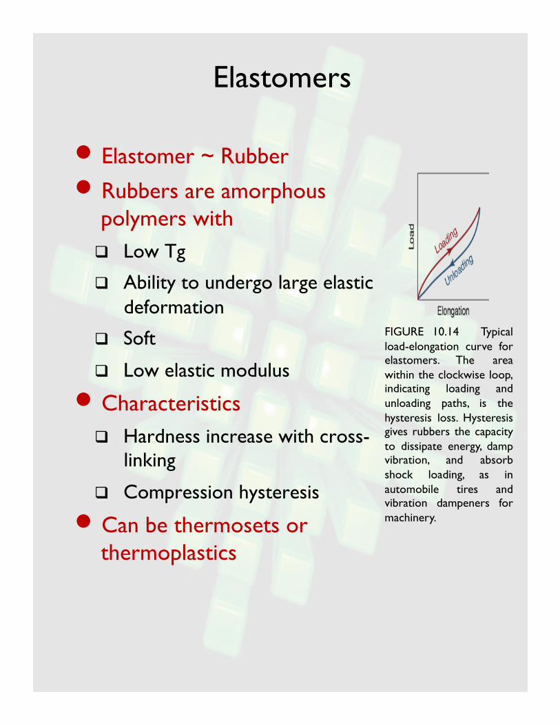
Elastomers
• Elastomer ~ Rubber
• Rubbers are amorphous polymers with Low Tg
Ability to undergo large elastic deformation
Soft
Low elastic modulus
• Characteristics Hardness increase with cross-
linking
Compression hysteresis
• Can be thermosets or thermoplastics
FIGURE 10.14 Typical load-elongation curve for elastomers. The area within the clockwise loop, indicating loading and unloading paths, is the hysteresis loss. Hysteresis gives rubbers the capacity to dissipate energy, damp vibration, and absorb shock loading, as in automobile tires and vibration dampeners for machinery.

Summary
• What is polymer/plastics
• Structure of polymers: mer vs polymer
• Characteristics of polymers
• Thermoplastics vs thermosets Difference
Characteristics
• Elastomers

Behavior of Thermoplastics
• Temperature effect
• Large elongation and orientation under tension
• Strain rate effect
• Viscoelasticity
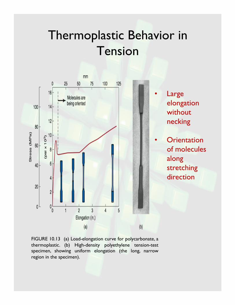
Thermoplastic Behavior in Tension
FIGURE 10.13 (a) Load-elongation curve for polycarbonate, a thermoplastic. (b) High-density polyethylene tension-test specimen, showing uniform elongation (the long, narrow region in the specimen).
• Large elongation without necking
• Orientation of molecules along stretching direction

Viscosity of Melted Polymers
• Measure of resistance of the polymer molecules in sliding along each other
• Depends on
Temperature
Pressure
Polymer structure
Molecular weight
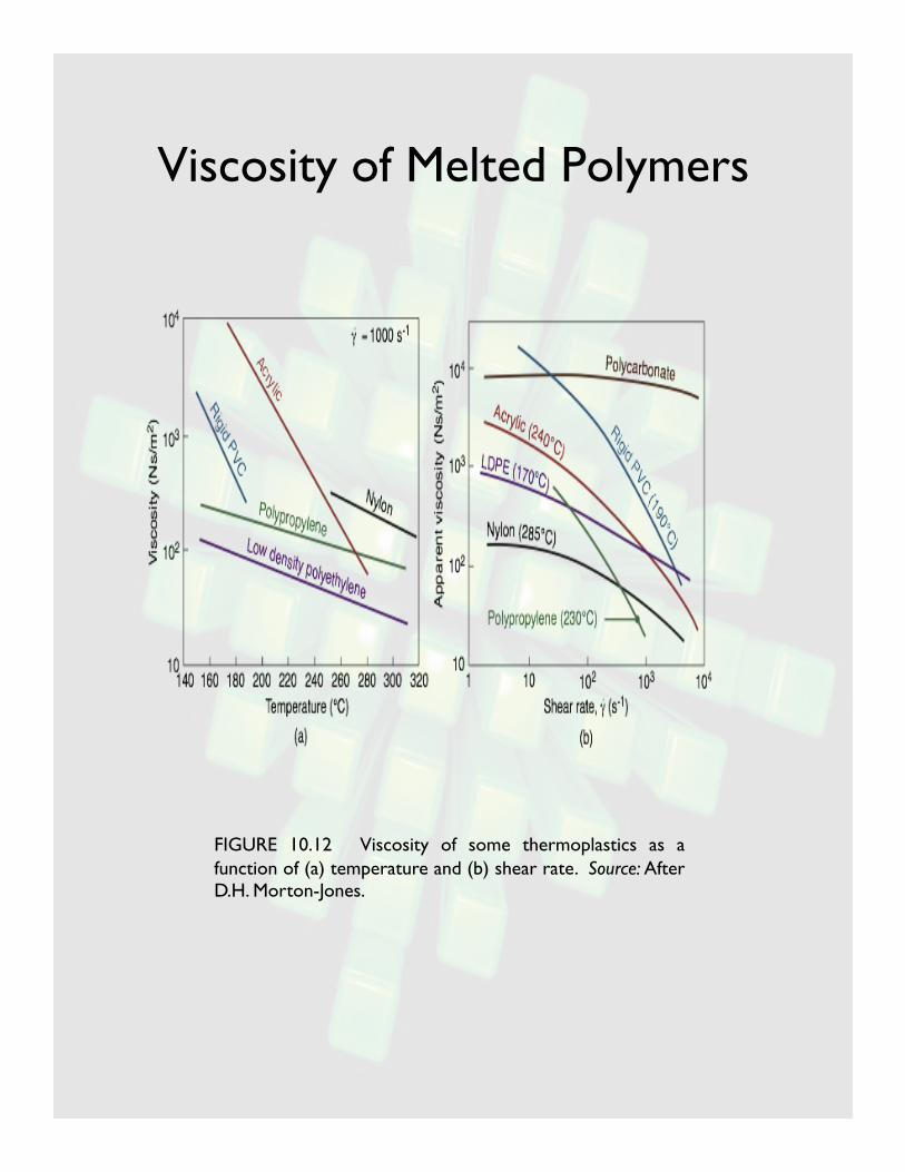
Viscosity of Melted Polymers
FIGURE 10.12 Viscosity of some thermoplastics as a function of (a) temperature and (b) shear rate. Source: After D.H. Morton-Jones.
Reinforced Plastics
• Composites
Combination of two or more chemically distinct and insoluble phases whose properties and structural performances are superior to the constituents acting independently
Types of Composites
• Polymer matrix (reinforced plastics)
• Metal matrix
• Properties of composites depend on:
Properties of individual components
Relative amounts
Size, shape, and distribution
Orientation
Degree of bonding
Applications of Reinforced Plastics
• Aerospace, automotive, marine, and construction industries.….
• Example: Boeing 787 Dreamliner
50% carbon-fiber composite (CFRP), in the fuselage, wings, tail, and interior components (100% of the skin, 80% by volume)
20% aluminum, primarily on the wing and tail leading edges
15% titanium, primarily in the engines
10% steel
5% other materials

Reinforced Plastics
FIGURE 10.15 Schematic illustration of types of reinforcing plastics. (a) Matrix with particles; (b) matrix with short or long fibers or flakes; (c) continuous fibers; and (d) and (e) laminate or sandwich composite structures using a foam or honeycomb core (see also Fig. 7.48 on making of honeycombs).
Matrix Materials
• Common matrix Usually thermosets
• Epoxy (80% of all reinforced plastics)
• Polyester (less expensive)
• Polyimides (for high temperature)
Thermoplastics
• PEEK (polyethetherketone) – high stiffness, low T resistance
• Matrix functions Support and transfer load to the fibers
Protect fibers against physical damage and environment
Reduce propagation of cracks by virtue of ductility and toughness

Reinforcing Fibers
• Common reinforcing fibers Polymer ( Kevlar (Aramid ), Spectra (PE)
Glass: S and E
Graphite (carbon)
Boron: CVD on W
• Fiber Length Short fiber (L/d=20-60)
Long fiber (L/d= 200-500)

Properties of Reinforcing Fibers
FIGURE 10.16 Specific tensile strength (ratio of tensile strength-to-density) and specific tensile modulus (ratio of modulus of elasticity-to-density) for various fibers used in reinforced plastics. Note the wide range of specific strength and stiffness available.
TABLE 10.4 Typical properties of reinforcing fibers.

Effect of Fibers
FIGURE 10.19 Effect of the percentage of reinforcing fibers and fiber length on the mechanical properties of reinforced nylon. Note the significant improvement with increasing percentage of fiber reinforcement. Source: Courtesy of Wilson Fiberfill International.

Strength and Fracture of Composites
FIGURE 10.20 (a) Fracture surface of glass-fiber-reinforced epoxy composite. The fibers are 10 µm (400 µin.) in diameter and have random orientation. (b) Fracture surface of a graphite-fiber-reinforced epoxy composite. The fibers are 9-11 µm in diameter. Note that the fibers are in bundles and are all aligned in the same direction.
FIGURE 10.21 Tensile strength of glass-reinforced polyester as a function of fiber content and fiber direction in the matrix. Source: After R.M. Ogorkiewicz.
Properties of Fiber-reinforced Composites
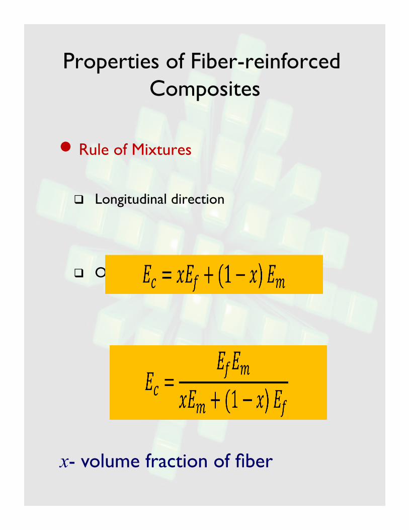
• Rule of Mixtures
Longitudinal direction
Orthogonal direction
x- volume fraction of fiber

Example
Assume that a graphite-epoxy-reinforced plastic with longitudinal fibers contains 20% graphite fibers, which have a strength of 2500 MPa, and elastic modulus of 300 GPa,. The strength of the epoxy matrix is 120 MPa, and it has an elastic modulus of 100 GPa.
Calculate:
a) The elastic modulus of the composite in the fiber direction
b) The fraction of load supported by the fiber if the load is applied in the fiber direction

Processing Techniques
• Plastics Extrusion
Injection molding
Blow molding
Thermoforming
• Reinforced plastics Impregnation
Molding processes
Filament winding, pultrusion, pulforming

Extrusion
• Accounts for largest production volume
• Produce long and uniform, solid and hollow parts Bars, tubes, sheets and films
• Mostly for thermoplastics
• High production rates, low tooling cost

Extrusion
• Hopper: feed raw materials (pellets, granules, powders)
• Screw: blends and conveys pellets down the barrel
Three sections: feed, melt (transition), melt-pumping
• Internal friction, shear stress & heater heats and liquefies pellets

Important Extrusion Parameters
• Process control parameters Temperature
Back pressure
Screw speed
Injection rate
Cooling after extrusion: air or water cool
• Typical geometric parameters D = 1 ~ 8 in.
L/D=5~30
• Difference from metal extrusion: screw

Injection Molding
• 3-D complex shapes
Cups, containers, housing, knobs, electrical components
• ~hot-chamber die casting
• Delivery of plastic Hydraulic plunger
Rotating screw
• Shape Split-die chamber
FIGURE 10.27 Injection molding with (a) a plunger and (b) a reciprocating rotating screw.
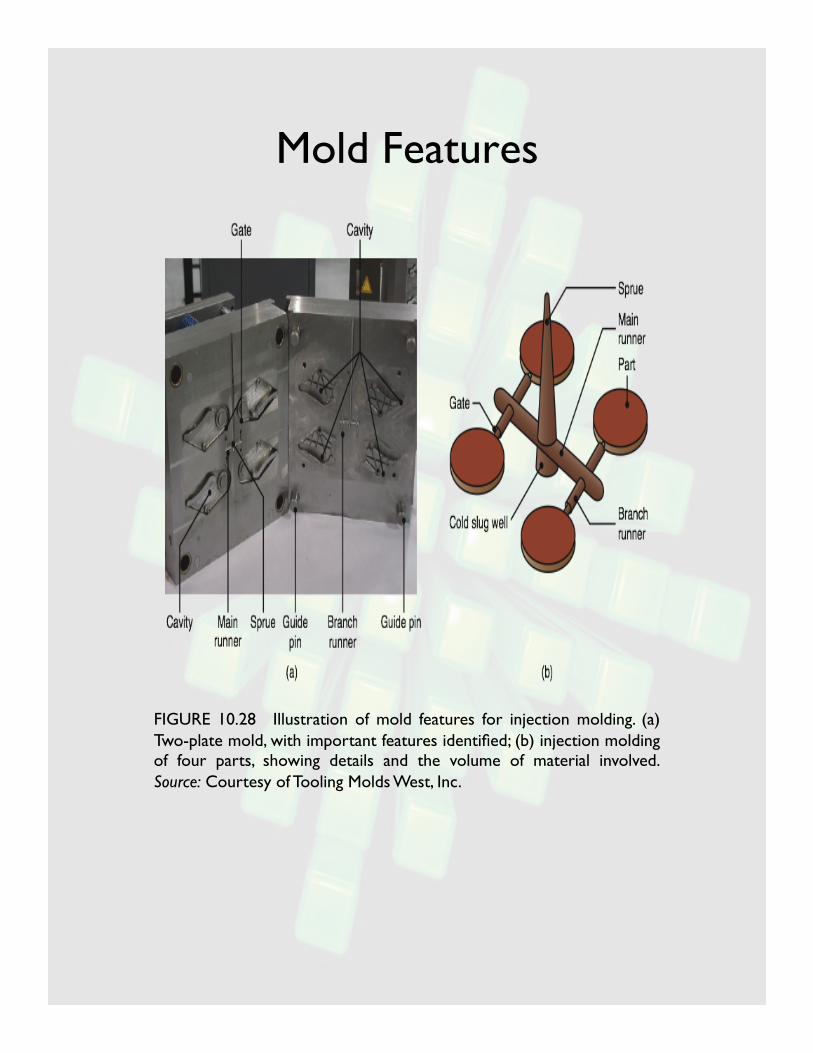
Mold Features
FIGURE 10.28 Illustration of mold features for injection molding. (a) Two-plate mold, with important features identified; (b) injection molding of four parts, showing details and the volume of material involved. Source: Courtesy of Tooling Molds West, Inc.

Insert Molding�
Metal components can be placed in the mold cavity (insert) to be integrated in the injection molded product
FIGURE 10.30 Products made by insert injection molding. Metallic components are embedded in these parts during molding. Source: (a) Courtesy of Plainfield Molding, Inc., and (b) Courtesy of Rayco Mold and Mfg. LLC.
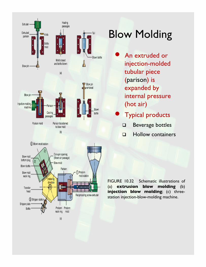
Blow Molding
• An extruded or injection-molded tubular piece (parison) is expanded by internal pressure (hot air)
• Typical products
Beverage bottles
Hollow containers
FIGURE 10.32 Schematic illustrations of (a) extrusion blow molding (b) injection blow molding; (c) three-station injection-blow-molding machine.

Thermoforming
• Forming thermoplastic sheet or film over a mold through applied heat and pressure or vacuum
• Procedure
Sheet is heated to sag point (softening, but below Tm)
Placed on mold, apply vacuum or pressure
Not applicable to parts with holes
Hollow parts can be made with twin sheets
FIGURE 10.35 Various thermoforming processes for thermoplastic sheet. These processes are commonly used in making advertising signs, cookie and candy trays, panels for shower stalls, and packaging.
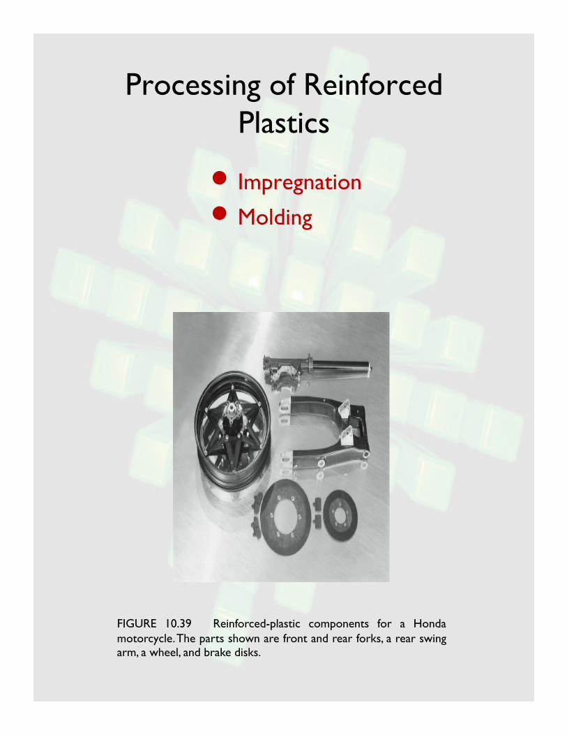
Processing of Reinforced Plastics
• Impregnation
• Molding
FIGURE 10.39 Reinforced-plastic components for a Honda motorcycle. The parts shown are front and rear forks, a rear swing arm, a wheel, and brake disks.
Impregnation of Fibers
• Surface treatment of reinforcing fibers (sizing)
• Partially cured sheets are referred to as: Prepregs
Sheet-molding compounds (SMC)
Bulk-molding compounds (BMC)
Thick-molding compounds (TMC)

Manufacture of Prepregs and SMCs
FIGURE 10.40 (a) Manufacturing process for polymer-matrix composite. Source: After T.-W. Chou, R.L. McCullough, and R.B. Pipes. (b) Boron-epoxy prepreg tape. Source: Textron Systems.
FIGURE 10.41 Manufacturing process for producing reinforced-plastic sheets. The sheet is still viscous at this stage and can later be shaped into various products. Source: After T.-W. Chou, R. L. McCullough, and R. B. Pipes. Example of SMC

Vacuum and Pressure Molding
FIGURE 10.42 (a) Vacuum-bag forming. (b) Pressure-bag forming. Source: After T. H. Meister.
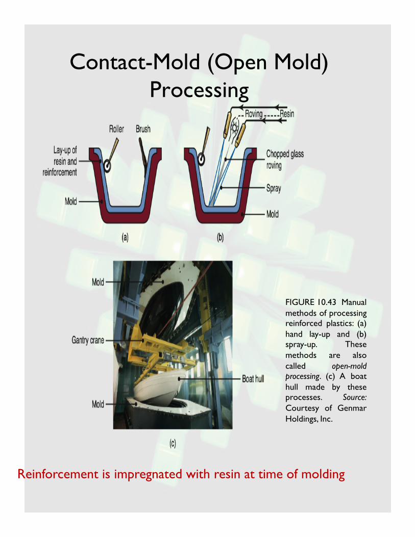
Contact-Mold (Open Mold) Processing
FIGURE 10.43 Manual methods of processing reinforced plastics: (a) hand lay-up and (b) spray-up. These methods are also called open-mold processing. (c) A boat hull made by these processes. Source: Courtesy of Genmar Holdings, Inc.
Reinforcement is impregnated with resin at time of molding
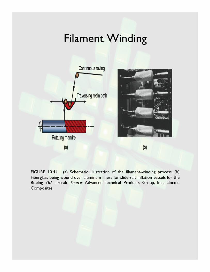
Filament Winding
FIGURE 10.44 (a) Schematic illustration of the filament-winding process. (b) Fiberglass being wound over aluminum liners for slide-raft inflation vessels for the Boeing 767 aircraft. Source: Advanced Technical Products Group, Inc., Lincoln Composites.

Pultrusion
FIGURE 10.45 (a) Schematic illustration of the pultrusion process. (b) Examples of parts made by pultrusion. Source: Courtesy of Strongwell Corporation.
Summary
• Processing of plastics
• Extrusion
• Injection molding
• Blow molding
• Thermoforming
• Processing of reinforced plastics
Impregnation
Molding
• Compression molding
• Vacuum bag molding
• Contact molding
• …
Other techniques
• Filament winding, pultrusion, pulforming
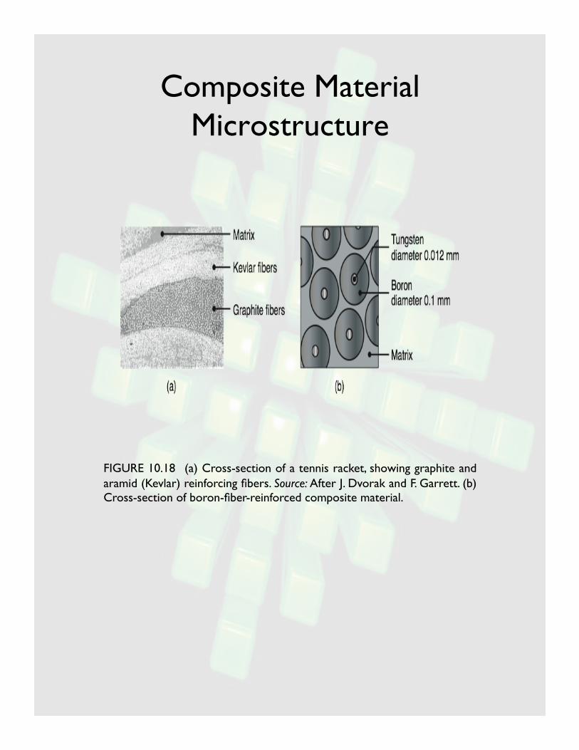
Composite Material Microstructure
FIGURE 10.18 (a) Cross-section of a tennis racket, showing graphite and aramid (Kevlar) reinforcing fibers. Source: After J. Dvorak and F. Garrett. (b) Cross-section of boron-fiber-reinforced composite material.

Applications for Plastics
TABLE 10.3 General recommendations for plastic products.