Structure Inspection Manual · Structure Inspection Manual . October 2018 1-3-4 8. Underwater...
35
Structure Inspection Manual October 2018 1-3-1 Table of Contents 1.3 Types of Bridge Inspections and Assessments .................................................................. 3 1.3.1 Introduction................................................................................................................. 3 1.3.2 Initial Inspection .......................................................................................................... 3 1.3.2.1 Purpose .............................................................................................................. 3 1.3.2.2 Precision ............................................................................................................. 5 1.3.2.3 Inventory Update/Rating of Repairs .................................................................... 5 1.3.2.4 Inspection Frequency .......................................................................................... 5 1.3.3 Routine Inspection ...................................................................................................... 5 1.3.3.1 Purpose .............................................................................................................. 5 1.3.3.2 Precision ............................................................................................................. 5 1.3.3.3 Routine Inspection Frequency............................................................................. 6 1.3.4 In-Depth Inspection .................................................................................................... 6 1.3.4.1 Purpose .............................................................................................................. 6 1.3.4.2 Precision ............................................................................................................. 8 1.3.4.3 In-Depth Inspection Frequency ........................................................................... 8 1.3.5 Fracture Critical Inspection ......................................................................................... 9 1.3.5.1 Purpose .............................................................................................................. 9 1.3.5.2 Precision ........................................................................................................... 10 1.3.5.3 Fracture Critical Inspection Frequency .............................................................. 11 1.3.6 Underwater Profile .................................................................................................... 12 1.3.6.1 Purpose ............................................................................................................ 12 1.3.6.2 Precision ........................................................................................................... 14 1.3.6.3 Inspection Frequency ........................................................................................ 15 1.3.6.4 Equipment......................................................................................................... 16 1.3.7 Underwater Inspection .............................................................................................. 16 1.3.7.1 Purpose ............................................................................................................ 16 1.3.7.2 Precision ........................................................................................................... 17 1.3.7.3 Underwater Diving Inspection Frequency .......................................................... 20 1.3.7.4 Methods of Underwater Inspection .................................................................... 21 1.3.7.5 Inspection Equipment and Tools ....................................................................... 22 1.3.8 Underwater Probing/Visual (Wading) Activity............................................................ 25 1.3.8.1 Inspection Equipment and Tools ....................................................................... 26 1.3.8.2 Underwater Probing/Visual Inspection Frequency ............................................. 26
Transcript of Structure Inspection Manual · Structure Inspection Manual . October 2018 1-3-4 8. Underwater...

Structure Inspection Manual
October 2018 1-3-1
Table of Contents
1.3 Types of Bridge Inspections and Assessments .................................................................. 3
1.3.1 Introduction ................................................................................................................. 3
1.3.2 Initial Inspection .......................................................................................................... 3
1.3.2.1 Purpose .............................................................................................................. 3
1.3.2.2 Precision ............................................................................................................. 5
1.3.2.3 Inventory Update/Rating of Repairs .................................................................... 5
1.3.2.4 Inspection Frequency .......................................................................................... 5
1.3.3 Routine Inspection ...................................................................................................... 5
1.3.3.1 Purpose .............................................................................................................. 5
1.3.3.2 Precision ............................................................................................................. 5
1.3.3.3 Routine Inspection Frequency ............................................................................. 6
1.3.4 In-Depth Inspection .................................................................................................... 6
1.3.4.1 Purpose .............................................................................................................. 6
1.3.4.2 Precision ............................................................................................................. 8
1.3.4.3 In-Depth Inspection Frequency ........................................................................... 8
1.3.5 Fracture Critical Inspection ......................................................................................... 9
1.3.5.1 Purpose .............................................................................................................. 9
1.3.5.2 Precision ........................................................................................................... 10
1.3.5.3 Fracture Critical Inspection Frequency .............................................................. 11
1.3.6 Underwater Profile .................................................................................................... 12
1.3.6.1 Purpose ............................................................................................................ 12
1.3.6.2 Precision ........................................................................................................... 14
1.3.6.3 Inspection Frequency ........................................................................................ 15
1.3.6.4 Equipment ......................................................................................................... 16
1.3.7 Underwater Inspection .............................................................................................. 16
1.3.7.1 Purpose ............................................................................................................ 16
1.3.7.2 Precision ........................................................................................................... 17
1.3.7.3 Underwater Diving Inspection Frequency .......................................................... 20
1.3.7.4 Methods of Underwater Inspection .................................................................... 21
1.3.7.5 Inspection Equipment and Tools ....................................................................... 22
1.3.8 Underwater Probing/Visual (Wading) Activity ............................................................ 25
1.3.8.1 Inspection Equipment and Tools ....................................................................... 26
1.3.8.2 Underwater Probing/Visual Inspection Frequency ............................................. 26

Structure Inspection Manual
October 2018 1-3-2
1.3.9 Interim Inspection ..................................................................................................... 26
1.3.9.1 Purpose ............................................................................................................ 26
1.3.9.2 Precision ........................................................................................................... 27
1.3.9.3 Interim Inspection Frequency ............................................................................ 28
1.3.10 Damage Inspection ................................................................................................. 28
1.3.10.1 Purpose .......................................................................................................... 28
1.3.10.2 Precision ......................................................................................................... 29
1.3.10.3 Damage Inspection Frequency ....................................................................... 29
1.3.11 Complex Bridge Inspection ..................................................................................... 30
1.3.11.1 Purpose .......................................................................................................... 30
1.3.12 Closed Bridge Inspection ........................................................................................ 30
1.3.12.1 Purpose .......................................................................................................... 30
1.3.12.2 Frequency ....................................................................................................... 31
1.3.13 Load Posted Verification ......................................................................................... 31
1.3.13.1 Purpose .......................................................................................................... 31
1.3.13.2 Precision ......................................................................................................... 31
1.3.13.3 Frequency ....................................................................................................... 32
1.3.14 Deck Evaluation ...................................................................................................... 32
1.3.14.1 Purpose .......................................................................................................... 32
1.3.14.2 Precision ......................................................................................................... 32
1.3.14.3 Frequency ....................................................................................................... 32
1.3.15 Scour Plan of Action ............................................................................................... 32
1.3.15.1 Purpose .......................................................................................................... 32
1.3.15.2 Precision ......................................................................................................... 33
1.3.15.3 Frequency ....................................................................................................... 33
1.3.16 Vertical Clearance Measured Activity ..................................................................... 33
1.3.16.1 Purpose .......................................................................................................... 33
1.3.16.2 Precision ......................................................................................................... 34
1.3.16.3 Frequency ....................................................................................................... 34
1.3.17 Critical Findings Activity .......................................................................................... 34
1.3.17.1 Purpose .......................................................................................................... 34
1.3.17.2 Precision ......................................................................................................... 35
1.3.17.3 Frequency ....................................................................................................... 35
Structure Inspection Manual
October 2018 1-3-3
1.3 TYPES OF BRIDGE INSPECTIONS AND ASSESSMENTS
1.3.1 Introduction
There are numerous types of bridge inspections. Each inspection type has been designed to obtain specific information from a structure. For instance, when a structure is built, an Initial Inspection is done to document the as-built condition of the structure and its structural elements. This is the baseline inspection, and all future inspection findings are compared to this information. Routine Inspections are performed at regular intervals to monitor the working condition of structure elements. This is the most common type of inspection. The results from a Routine Inspection are used to assess structure safety and structure maintenance needs. Interim Inspections are used to monitor known defects in a structure.
All of the inspection types that are used by the Wisconsin Department of Transportation (WisDOT) help to create a complete picture of a structure’s condition and are described in detail in this chapter.
1.3.2 Initial Inspection
1.3.2.1 Purpose
CFR 650.305 states: Initial Inspection. The first inspection of a bridge as it becomes a part of the bridge file to provide all Structure Inventory and Appraisal (SI&A) data and other relevant data and to determine baseline structural conditions.
An Initial Inspection is the baseline inspection that shall be completed on every new structure preferably before but no later than 30 days after the structure is open to public traffic. An Initial Inspection is a fully documented inspection, using the structure plans, to determine basic data about the structure for entry into the Highway Structures Information System (HSIS) file.
Data gathered for Initial Inspections should include the following:
1. An existing set of plans, as-builts, shop drawings, design computations, and hydraulic computations for the bridge (if applicable).
2. An analytical determination of load capacity (performed by a qualified Wisconsin professional engineer).
3. All Structure Inventory and Appraisal (SI&A) data required by federal and state regulations.
4. Other relevant information required by the department to maintain an accurate bridge file.
5. Baseline structural conditions and element quantities.
6. Any existing problems or locations in the structure that may have potential problems.
7. Location and condition of any fracture critical members or details.

Structure Inspection Manual
October 2018 1-3-4
8. Underwater channel profiles at the upstream and downstream fascia (for structures over water).
9. Using the profile information, assessment of the need for future underwater dive inspections.
When an initial inspection is conducted, a Structure Inventory and Appraisal Field Review must be completed and entered into the Highway Structures Information (HSI) System. This form can be generated by the HSI software for each bridge in the state and must be verified for accuracy at least once every 48 months.
As part of the Initial Inspection, inspectors need to review the appropriate inspection types required on the structure, and verify that the HSIS system has those inspection types flagged.
For instance, imagine a steel bridge with a two-girder superstructure system spanning a waterway. The bridge has a supporting pier in the middle of the channel. First, a two-girder superstructure system does not provide redundant load paths. Should one girder fail, the entire bridge will collapse, and therefore the structure is fracture critical. Next, the pier in the channel has affected the normal flow pattern of the water. As a result, the stream channel and the pier foundation may be subject to scour action. Finally, the depth of the stream or the turbidity of the water may obscure the visibility of the pier foundation. It is foreseeable, then, that this bridge will require a fracture critical inspection, and possibly an underwater inspection. Once the inspector has decided what inspection types the structure will require, he/she should complete the appropriate boxes for the associated inspection frequencies in HSIS and notify the Inspection Program Manager.
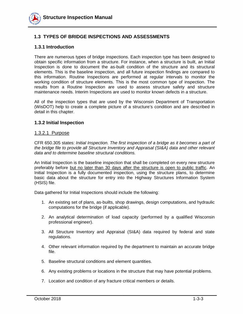
Figure 1.3.2.1-1: Inspector Performing an Initial Inspection.

Structure Inspection Manual
October 2018 1-3-5
1.3.2.2 Precision
The Initial Inspection is required to document “as-built” conditions, not whether the structure was constructed per Plans and Specifications. Since this is a baseline inspection, all deficiencies, cracks, construction errors, alignment problems, etc. should be quantified and documented. The compiled documentation will be used during future inspections to determine if defects discover in the future existed when the structure was constructed or if they have materialized from the loading applied to the structure.
1.3.2.3 Inventory Update/Rating of Repairs
Since both the National Bridge Inventory (NBI) and Element Level rating scales are based upon existing structural conditions, repairs may improve the condition ratings assigned to a structure. When work is completed on an existing structure, an Interim inspection shall be entered into the HSIS that takes into account the new structural condition.
1.3.2.4 Inspection Frequency
Each newly constructed or rehabilitated structure shall receive an Initial Inspection or Interim Inspection within 30 days of opening the structure to traffic. WisDOT prefers that an Initial Inspection be completed before the structure is open to traffic. An initial inspection should preferably be completed before a construction contract can be finalized.
1.3.3 Routine Inspection
1.3.3.1 Purpose
CFR 650.305 states: Routine Inspection. Regularly scheduled inspection consisting of observations and/or measurements needed to determine the physical and functional condition of the bridge, to identify any changes from initial or previously recorded conditions, and to ensure that the structure continues to satisfy present service requirements.
1.3.3.2 Precision
Routine inspections are generally conducted from the deck, ground, or water level or from permanent work platforms and walkways. If any element of the bridge appears to be distressed, the inspector should take a closer look at that element. Critical load-carrying members (e.g., steel and concrete girders, decks, slabs, concrete box girders, piers and bents, bearings, abutments) should be closely monitored. Failure prone details or elements should receive a detailed, close-up (arm’s length) inspection. See Section 3.6, Fracture Critical Inspection and Part 2 Appendix D, Fatigue Prone Details for typical critical details. Inspection of underwater portions of the substructure is limited to observations during low-flow periods, probing for signs of undermining, and streambed profile measurements where applicable. This is further discussed in Section 3.9 All inspection results should be fully documented on the report form stored in HSIS.
Any changed or deteriorated structural conditions that might affect previously recorded bridge load ratings should be noted on the inspection form. If the inspector determines that a new load rating is warranted, the “load rating” box should be marked with a “Y”. The owner is responsible for rating the structure. That owner is also responsible for getting the updated

Structure Inspection Manual
October 2018 1-3-6
structure data into the appropriate structure file(s) located in the HSI. The HSI electronic file is the Official Bridge File in accordance with Metric 15 of the NBIS Metrics for the Overview of the National Bridge Inspection Program.
Public safety is the primary concern of the structure inspector. Therefore, the inspector should make sure Wisconsin’s structures are physically safe as well as structurally stable. Special attention should be paid to the condition of parapets, railings, pedestrian fencing, guardrail, sidewalks, spalling concrete surfaces, and other safety related members. The following are examples of conditions that may warrant documentation and notification of the Local, County or Region Manager:
1. trip hazards, severe approach settlement, or large spalls on sidewalks;
2. rebar protruding from decks, walks, or parapets;
3. loose, missing, or damaged railings or parapets;
4. missing or damaged guardrail;
5. loose concrete that could fall onto a traveled way (road, walk, bike path, waterway, or rail line); and
6. any other condition that the inspector perceives as a threat to public safety.
The inspector may have several documents available to assist him in organizing and performing the inspection. These documents include: as-built plans, original shop drawings, as-built repair plans and shop drawings, and previous inspection reports.
1.3.3.3 Routine Inspection Frequency
For structures that:
• Are load posted at less than 40 tons, or
• Have a NBI file value for Superstructure (Item 59), Substructure (Item 60), or Culvert (Item 62) of 4 or less
These structures are considered High-Risk and shall have a Routine inspection every 12 months.
For all other structures, a 24-month Routine inspection cycle is required.
1.3.4 In-Depth Inspection
1.3.4.1 Purpose
An In-Depth Inspection is a visual, hands-on inspection of one or more structure elements above or below water level that may be supplemented by non-destructive evaluation. This higher-level inspection can be performed on any structure type, though it is commonly

Structure Inspection Manual
October 2018 1-3-7
performed on steel superstructure bridges with problematic details that need close up evaluation (as discussed below).
The exception to this is fracture critical bridges, which have a federally mandated “In-Depth” inspection of all primary tension members. This specific type of In-Depth is called a Fracture Critical Inspection, and is entered into the Highway Structures Information (HSI) System as a Fracture Critical Inspection only. More information on this inspection type can be found in section 1.1.2 of this manual.
An In-Depth Inspection can be scheduled independently of a Routine Inspection, though generally at a longer interval, or it may be a follow-up for a Damage Inspection. Generally, specialized equipment is required to obtain the necessary hands-on, arm’s reach access to the element (snooper trucks, scissor lifts, ladders, etc.).
On small bridges, it may be practical to include all elements of the structure during the inspection. In this case, both the Routine and In-Depth boxes shall be checked in the Highway Structures Information (HSI) System when entering the inspection. If NDE is used during this inspection, or any other inspection type, the activity type for Non-Destructive Evaluation should also be checked.
For large and complex structures, In-Depth Inspections may be scheduled separately for defined segments of the bridge or for designated groups of elements, connections, or details that can be efficiently addressed by the same or similar inspection techniques. If the latter option is chosen, each defined bridge segment and/or each designated group of elements, connections, or details should be clearly identified in the inspection procedures and inspection specific notes as a matter of record.
The activities, procedures, and findings of In-Depth Inspections should be thoroughly documented with appropriate photographs, test results, measurements, and a written report in the HSI system. In addition, access methods must be clearly documented so that future scheduling needs can be determined.
WisDOT requires an In-Depth inspection at a defined interval for the structures mentioned in section 1.3.5.3. However, there are other conditions and/or structural details that may prompt an unscheduled In-Depth Inspection.
Several common conditions or structural details that could prompt an In-Depth Inspection (and possibly NDE) include:
• Apparent cracks in steel members
• Apparent cracks, de-bonding or loss of tendon section in a Prestressed or post-tensioned member
• Heavily corroded or failed hold down devices.
• Severe section loss in a steel member or primary gusset plate
• Buckled or bent steel girders or beams.
• Welded cover plate end terminations
Structure Inspection Manual
October 2018 1-3-8
• Live load bearing anchor pins, and link-bars
• Field welds on tension members
• Intersecting welds, or category D, E, or E’ details
• Unique or Problematic Details
The decision to conduct an unscheduled, In-Depth Inspection, with or without the use of NDE, is the responsibility of the Regional Program Manager. Items to consider when making this decision include (but are not limited to) ADT, Condition, Age and Location.
1.3.4.2 Precision
As indicated previously, an In-Depth Inspection is a visual, hands-on inspection of one or more structural elements. Each element under investigation should be within arm’s reach of the inspector. The inspection may include a recommendation for a load rating to assess the residual capacity of damaged or deteriorated members, depending on the extent of the damage or deterioration. Nondestructive load tests may be conducted to assist in determining a safe bridge load-carrying capacity. The inspector should exercise sound judgment in recommending when a load capacity analysis is warranted.
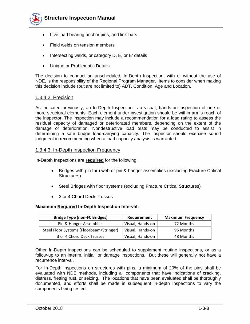
1.3.4.3 In-Depth Inspection Frequency
In-Depth Inspections are required for the following:
• Bridges with pin thru web or pin & hanger assemblies (excluding Fracture Critical Structures)
• Steel Bridges with floor systems (excluding Fracture Critical Structures)
• 3 or 4 Chord Deck Trusses
Maximum Required In-Depth Inspection Interval:
Bridge Type (non-FC Bridges) Requirement Maximum Frequency Pin & Hanger Assemblies Visual, Hands-on 72 Months
Steel Floor Systems (Floorbeam/Stringer) Visual, Hands-on 96 Months 3 or 4 Chord Deck Trusses Visual, Hands-on 48 Months
Other In-Depth inspections can be scheduled to supplement routine inspections, or as a follow-up to an interim, initial, or damage inspections. But these will generally not have a recurrence interval. For In-Depth inspections on structures with pins, a minimum of 20% of the pins shall be evaluated with NDE methods, including all components that have indications of cracking, distress, fretting rust, or seizing. The locations that have been evaluated shall be thoroughly documented, and efforts shall be made in subsequent in-depth inspections to vary the components being tested.

Structure Inspection Manual
October 2018 1-3-9
1.3.5 Fracture Critical Inspection
1.3.5.1 Purpose
CFR 650.305 defines a Fracture Critical Inspection as: A hands-on inspection of a fracture critical member or member components that may include visual and other nondestructive evaluation. A fracture critical inspection is a specific type of In-Depth inspection. However, since it is specifically called out in the Code of Federal Regulations, Fracture Critical Inspections must be coded separately from In-Depth inspections on the National Bridge Inventory submittal and in HSI.
The AASHTO Manual for Bridge Evaluation (MBE), 2nd Edition, defines a fracture critical member (FCM) as "steel tension members or steel tension components of members whose failure would be expected to result in a partial or full collapse of the bridge."
Common FCM’s include (but not limited to):
• Tie girders on tied arch bridges
• Tension chords or diagonals on trusses
• Primary gusset plates connecting FCM’s
• Tension flanges on non-redundant girders
• Tension flanges on non-redundant pier cap beams
• Pins on non-redundant girder/truss bridges
• Tension flanges on non-redundant floor beams
Fracture Critical Inspections are regularly scheduled inspections. FCMs require more thorough and detailed inspections than the members of non-fracture critical bridges. In recognition of this, Federal Regulation 23 CFR 650.313(e)(1) requires all states to establish Fracture Critical Bridge Inspection procedures.

Structure Inspection Manual
October 2018 1-3-10
Figure 1.3.5.1-1: Inspectors Performing a Fracture Critical Member Inspection Bridges with FCMs have written inspection procedures which clearly identify the location of all FCMs, specify the frequency of inspection, describe any specific risk factors unique to the bridge, and clearly detail inspection methods and equipment to be employed.
A Fracture Critical Inspection can be scheduled independently of a Routine Inspection, though it is common to schedule both during the same inspection. Generally, specialized equipment is required to obtain the necessary hands-on, arm’s reach access to the element (snooper trucks, scissor lifts, ladders, etc.).
On small bridges, it is practical to include all elements of the structure during the inspection. In this case, both the Routine and Fracture-Critical boxes shall be checked in the Highway Structures Information (HSI) System when entering the inspection.
For large and complex structures, the Fracture-Critical Inspection may be scheduled separately. If this option is chosen, each defined FCM shall be clearly identified in the inspection procedures and inspection specific notes as a matter of record.
The activities, procedures, and findings of Fracture Critical Inspections should be thoroughly documented with appropriate photographs, test results, measurements, and a written report in the HSI system. In addition, access methods must be clearly documented so that future scheduling needs can be determined.
1.3.5.2 Precision
A Fracture Critical Member Inspection is a hands-on inspection (a specific type of In-Depth inspection). CFR 650.305 states a Hands-on Inspection as: Inspection within arm’s length of the component. Inspection uses visual techniques that may be supplemented by nondestructive testing. Every square foot of the member/member component is examined. The observations and/or measurements are used to determine the structural capacity of the member/member component, to identify any changes from previous Fracture Critical

Structure Inspection Manual
October 2018 1-3-11
Member Inspections, and to ensure that the structure continues to satisfy present safety and service requirements.
Under-bridge access equipment is typically required to move the inspector within arm’s length of the critical members. There may be permanent work platforms and walkways available on some larger structures to aid in inspection work. The access methods used during the inspection must be documented in the inspection procedures.
1.3.5.3 Fracture Critical Inspection Frequency
In Wisconsin, visual/hands-on Fracture Critical Inspections are required at regular intervals not to exceed 24 months (more frequently is acceptable). When any portion of a fracture critical member is in condition state 4, then the Fracture Critical inspection interval shall not exceed 12 months for that member.
Maximum Required Inspection Interval:
Hands-on/Visual ..................................................................................................... 24 months Nondestructive Evaluation (NDE) ............................................................................ 72 months
Details to consider for NDE Evaluation of Fracture Critical Components include:
• Pin and hanger assemblies
• Live load bearing anchor pins and link bars
• Pin thru web assemblies
• Welded cover plate end terminations on FCM’s
• Field welds on FCM’s
• Intersecting welds, or category D, E, or E’ details on FCM’s
• Unique or Problematic Details on FCM’s

Structure Inspection Manual
October 2018 1-3-12
Figure 1.3.5.3-1: Inspector Performing Ultrasonic Testing for Crack Detection.
1.3.6 Underwater Profile
1.3.6.1 Purpose
Scour is the leading cause of bridge failures. Federal Highway Administration (FHWA) regulations have been expanded to require bottom profiling and maintenance of channel records. The FHWA regulations reference the 2008 American Association of State Transportation and Highway Officials (AASHTO) The Manual for Bridge Evaluation, 1st Edition, which provides more specific information. Accordingly, the Department shall maintain such records on applicable bridges and ensure that local units of government do likewise.
Since this work is essentially a surveying task, the individuals taking the profiles need not be certified bridge inspectors. However, the profiles must be reviewed and compared to known substructure elevations and past profiles by the Inspection Team Leader (ITL) or Program Manager.
All structures over water shall have an initial underwater profile activity taken during the initial inspection. The results shall be entered into HSI with documentation that show or explain the profile.
The HSI system will allow the uploading of numerous file formats including Excel spreadsheets. At the inspector’s discretion, a spreadsheet may be created for a structure and uploaded to the HSI system for future reference and modification, if necessary.
At a minimum, profiles shall be taken at the upstream and downstream fascia. It is not required to profile around substructure units (as these are covered by probing and/or Underwater Dive Inspections), but this may be done during the profile activity as directed by the inspection team leader or the inspection program manager.
Follow-up Underwater Profile Activities
Higher Risk Bridges – Structures in this category Include:

Structure Inspection Manual
October 2018 1-3-13
• Bridges that are scour critical, having a code of 3 or less, or U for NBI Item 113 or
• Bridges that have NBI Channel (Item 61) coded at 5 or below or
• Bridges that have a scour defect (6000) in Condition State 3 or 4.
Bridges meeting these criteria shall have profiles taken every 24 months on both the upstream and downstream fascia.
The inspector and PM shall review the historic profile measurements to ascertain potential movement of the channel and risk of substructure undermining and if such risk exists, notify the Statewide Program Manager.
Structures involved in a significant flooding event – Structures over water that experience a significant flooding event shall have a post flood profile evaluation to ensure the channel hasn’t significantly shifted to affect the structural integrity of the bridge. A significant flood event is defined as one that causes the stream to flow beyond its banks.
Subsequent profile measurements for structures over water that do not meet the above criteria are not required, but should be scheduled by the PM if conditions in the field warrant follow-up actions.
In Conjunction with Underwater Dive Inspection
Structures that also require Underwater Dive inspections shall have extensive profiles taken at the Dive inspection interval, and may forgo the 24-month requirements previously mentioned; water depth measurements during an underwater inspection should also include the following “global area” locations:
1. Bottom elevations around each substructure unit in the water.
2. Bottom elevations at sufficient intermediate points between substructure units at the upstream fascia, downstream fascia, 100 feet upstream, 200 feet upstream, 100 feet downstream, and 200 feet downstream to adequately determine the thalweg of the waterway. Where the structure length is less than 100 feet, the upstream and downstream profiles should be taken at locations equal to the structure length and twice the structure length.
3. Termini of upstream and downstream profiles shall be referenced or monumented to ensure that subsequent profiles are taken at the same locations. GPS coordinates are acceptable.
Scour is the movement of channel bed material by the action of the moving water. This movement may result in degradation, or erosion, of material as well as aggradation, or accumulation of material. Degradation of the channel bed may lead to structure instability, posing an often-unseen threat to safety.
There are three forms of scour that can affect the safety of bridges and waterfront structures.

Structure Inspection Manual
October 2018 1-3-14
1. General scour is the general degradation or loss of the bed material along a considerable length of a waterway. It can be the result of natural erosion, mining activities, construction, or other events.
2. Contraction scour involves the removal of material from the bed and banks across all or the majority of the width of a channel. Contraction scour is caused by a reduction in the upstream channel cross-section, which results in increased flow velocities, increased bed shear stresses, and subsequent loss of material.
3. Local scour is the removal of material from a smaller area and is restricted to a minor portion of the width of the channel. The main mechanism of local scour is the formation of vortices at the base of piers, piles or other substructure elements as a result of currents, propeller wash, discharge/intake pipes, or other factors.
As discussed in Section 1.3.8, divers should note any signs of scour during underwater inspections. An important assessment during any inspection is how much of the substructure foundation is exposed when compared to design plans.
The inspector should check for scour at every structure over a waterway. The inspector should be aware that scour is generally most severe during periods of high flow1 and when flows recede to normal levels; the presence of scour is often covered up with silt or timber debris, making detection difficult. Comparison of previous profiles is typically needed to detect and assess general and contraction scour.
Figure 1.3.7.1-1: Local Scour at the Base of an Abutment.
1.3.6.2 Precision
Hydrographic survey data is used to evaluate trends in channel bottom movement and to compare channel bottom elevations to footing elevations. Water depth measurements should 1 High flows following a major rainfall event can generally be expected to occur about 12 hours after precipitation ceases as a rough rule of thumb; however, every waterway is different, based on a variety of factors.
Structure Inspection Manual
October 2018 1-3-15
typically be recorded to the nearest tenth of a foot. However, scour evaluations are typically based on changes in elevations greater than 0.5 foot since most channel bottoms are irregular surfaces with random cobbles, debris, and sand ripples.
It is generally an acceptable practice for scour inspectors to measure the water depth relative to the water surface, in waterways without steep profiles or obvious hydraulic drops, assuming the waterline elevation in most waterways is constant over the surveyed area adjacent to the bridge. In actuality, since water always flows toward a lower topographic elevation, it is common for there to be at least 0.1 foot decrease in water surface elevation over a length of 500 feet in most waterways in Wisconsin. For waterways with steep profiles or obvious hydraulic changes in the water surface elevation, all water surface elevations must be recorded if direct water depth measurements are taken. Rather than documenting several water surface elevations, the inspector may choose to record the channel bottom elevation to a constant elevation using a surveyor’s level or total station equipment.
During all underwater surveys, the water surface elevation shall always be referenced to a known elevation on or near the bridge.
In most instances, a bridge profile is located on a tangent or vertical curve. In order to expedite the streambed profile, the Wisconsin DOT recommends determining the elevation of an accessible bridge component. For example, the top of a bridge rail, or edge of deck are common landmarks an inspector can utilize when taking streambed elevations. The purpose of the profile is to observe changes to the streambed from inspection to inspection. So long as every inspector subsequently uses the same landmark and elevation for data recording, an accurate account is developed. Therefore it is imperative that the inspector clearly identify the elevation of the landmark (these can be derived off existing plans or arbitrarily chosen) and the location the measurements are taken from (e.g. North Abutment - Upstream Fascia at Centerline of Bearing). When using an arbitrary elevation, the inspector may assume a constant elevation along the length of the structure, even if located on a vertical profile. Again, this is acceptable because the profile is a comparative tool. So long as the subsequent inspections replicated this arbitrary elevation and the locations at which measurements are taken, the data shall indicate whether there have been any changes to channel alignment or elevation.
While the true streambed elevation determined may be skewed due to the bridge profile following a tangent or vertical curve, the data will be able to be compared to later inspections.
1.3.6.3 Inspection Frequency
1. All structures over water are required to have at least one underwater profile on file.
2. Higher Risk Structures, as defined in section 1.3.6.1, shall have profiles every 24 months.
3. Structures that require underwater dive inspections shall have Global area profiles at 60 months and can forgo the 24-month requirement.

Structure Inspection Manual
October 2018 1-3-16
1.3.6.4 Equipment
Several water depth measurement methods, with a variety of equipment, can be used during a scour inspection with a hydrographic survey. These water depth measurements, often called soundings, can be obtained by manual means (lead line or sounding pole) or technological equipment (fathometer, sonar, radar, etc.). Refer to Chapter 19 in Part 5 for information on underwater profile equipment.
1.3.7 Underwater Inspection
1.3.7.1 Purpose
CFR 650.305 states the following definition for underwater inspection: Inspection of the underwater portion of a bridge substructure and the surrounding channel, which cannot be inspected visually at low water by wading or probing, generally requiring diving or other appropriate techniques.
Furthermore, Metric #17 of the NBIS Metrics for Overview of the National Bridge Inspection Program states the following:
Bridges requiring UW inspections have written inspection procedures which clearly identify the location of all UW elements, specify the frequency of inspection, describe any specific risk factors, and clearly detail inspection methods and equipment to be employed.
Underwater Diving Inspections are a necessary part of an effective structure management program, and are mandated by the Federal Highway Administration (FHWA) on routine intervals not to exceed 60 months. Underwater diving inspections should be completed in accordance with OSHA 29 CFR 1910 SUBPARTS T AND Y, and the requirements described in this section. An underwater diving structure inspection is required if water conditions exist at the structure that prohibit access to all portions of an element by visual or tactical means ensuring a level of certainty during Routine Inspections.
These specialized inspections serve an important part in protecting the public, providing reliable service, and reducing maintenance and construction costs. Structural conditions above water that could lead to failure, loss of life or property damage are often observed well in advance by inspectors, maintenance workers, and sometimes even passing motorists. Conversely, significant underwater structural conditions cannot be observed by these individuals until the defect has progressed to the point where distress is evident above water. Unfortunately, structures exhibiting significant underwater defects often collapse before the distress is evident above water.
Although each type of material has predominant mechanisms of deterioration, the environment (moderate temperatures, moisture, oxygen, and chlorides or other chemicals) at the waterline is most conducive to all forms of deterioration. Furthermore, unique mechanisms, such as bacterial corrosion, are also common near the waterline on structures. This deterioration and distress may not be recognizable from above water, nor can the extent and severity be determined in most cases without inspecting the underwater elements.
Structure Inspection Manual
October 2018 1-3-17
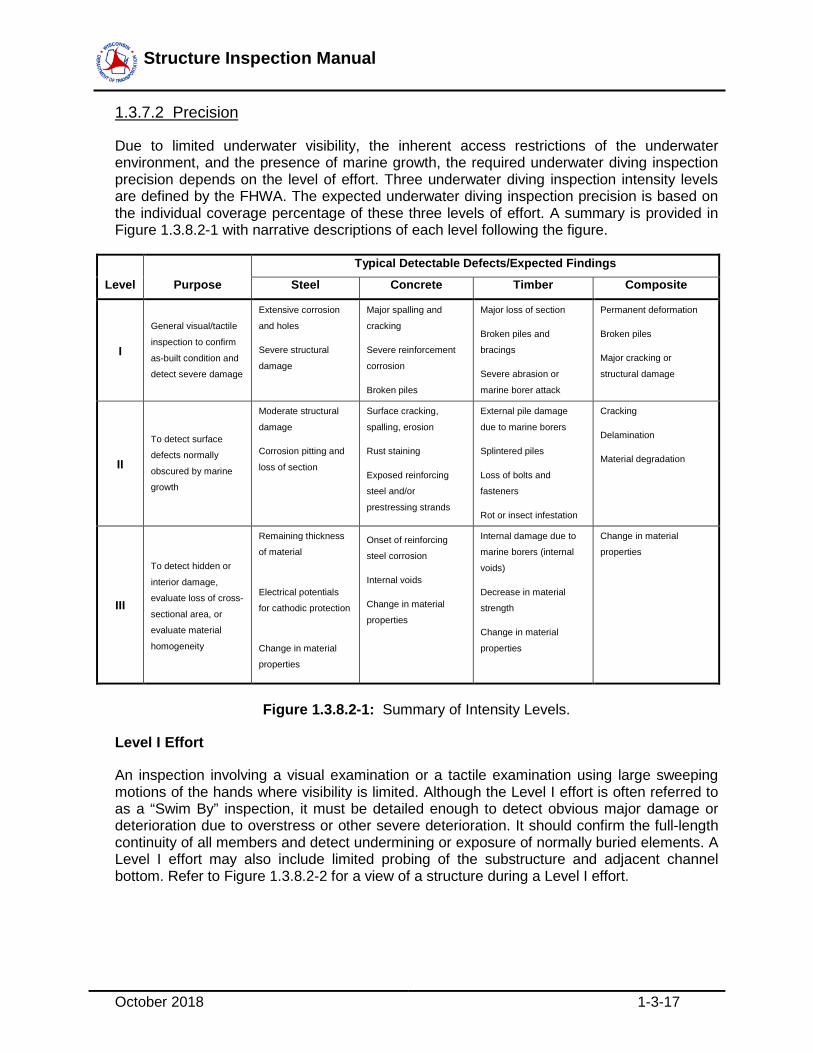
1.3.7.2 Precision
Due to limited underwater visibility, the inherent access restrictions of the underwater environment, and the presence of marine growth, the required underwater diving inspection precision depends on the level of effort. Three underwater diving inspection intensity levels are defined by the FHWA. The expected underwater diving inspection precision is based on the individual coverage percentage of these three levels of effort. A summary is provided in Figure 1.3.8.2-1 with narrative descriptions of each level following the figure.
Level Purpose
Typical Detectable Defects/Expected Findings
Steel Concrete Timber Composite
I
General visual/tactile
inspection to confirm
as-built condition and
detect severe damage
Extensive corrosion
and holes
Severe structural
damage
Major spalling and
cracking
Severe reinforcement
corrosion
Broken piles
Major loss of section
Broken piles and
bracings
Severe abrasion or
marine borer attack
Permanent deformation
Broken piles
Major cracking or
structural damage
II
To detect surface
defects normally
obscured by marine
growth
Moderate structural
damage
Corrosion pitting and
loss of section
Surface cracking,
spalling, erosion
Rust staining
Exposed reinforcing
steel and/or
prestressing strands
External pile damage
due to marine borers
Splintered piles
Loss of bolts and
fasteners
Rot or insect infestation
Cracking
Delamination
Material degradation
III
To detect hidden or
interior damage,
evaluate loss of cross-
sectional area, or
evaluate material
homogeneity
Remaining thickness
of material
Electrical potentials
for cathodic protection
Change in material
properties
Onset of reinforcing
steel corrosion
Internal voids
Change in material
properties
Internal damage due to
marine borers (internal
voids)
Decrease in material
strength
Change in material
properties
Change in material
properties
Figure 1.3.8.2-1: Summary of Intensity Levels.
Level I Effort
An inspection involving a visual examination or a tactile examination using large sweeping motions of the hands where visibility is limited. Although the Level I effort is often referred to as a “Swim By” inspection, it must be detailed enough to detect obvious major damage or deterioration due to overstress or other severe deterioration. It should confirm the full-length continuity of all members and detect undermining or exposure of normally buried elements. A Level I effort may also include limited probing of the substructure and adjacent channel bottom. Refer to Figure 1.3.8.2-2 for a view of a structure during a Level I effort.

Structure Inspection Manual
October 2018 1-3-18
Figure 1.3.8.2-2: Inspector Conducting a Level I Inspection Effort.
Level II Effort
A Level II effort is a detailed inspection that requires marine growth to be removed from portions of the structure. Cleaning is time-consuming so there is a need to limit the detailed inspection to a representative sampling of components. For piles, a 12-inch high band should be cleaned at designated locations, generally near the waterline, at the mudline, and midway between the waterline and the mudline. On an H-pile, marine growth should be removed from both flanges and the web. On a rectangular pile, the marine growth removal should include at least three sides; on an octagonal pile, at least six sides; on a round pile, at least three-fourths of the perimeter. On large diameter piles, three feet or greater, one-foot squares should be cleaned at four locations approximately equally spaced around the perimeter, at each elevation. On large solid faced elements such as pier shafts, one-foot squares should be cleaned at four random locations, at each elevation. The Level II effort should also focus on typical areas of weakness such as attachment points and welds. The Level II effort is intended to detect and identify damaged and deteriorated areas that may be hidden by surface biofouling. The thoroughness of cleaning should be governed by what is necessary to discern the condition of the underlying material. Removal of all biofouling staining is generally not required. Refer to Figure 1.3.8.2-3 for a view of a structure during a typical Level II effort.

Structure Inspection Manual
October 2018 1-3-19
Figure 1.3.8.2-3: Inspector Conducting a Level II Inspection Effort.
Level III Effort
A detailed inspection typically involving nondestructive evaluation (NDE) or partially-destructive evaluation (PDE), conducted to detect hidden or interior damage, or to evaluate material homogeneity. Typical inspection and testing techniques include the use of ultrasonic, coring or boring, physical material sampling, and in-situ hardness testing. Level III testing is generally limited to key structural areas, areas which are suspect or areas which may be representative of the underwater structure. Refer to Part 5 of this Manual for additional information on nondestructive and partially destructive evaluation. Also, refer to Figures 1.3.8.2-4 and 1.3.8.2-5 for views of inspectors conducting Level III efforts.
Figure 1.3.8.2-4: Inspector Using a D-Meter to Conduct a Level III NDE Inspection Effort.

Structure Inspection Manual
October 2018 1-3-20
Figure 1.3.8.2-5: Inspector Using a Drill to Conduct a Level III PDE Inspection Effort.
1.3.7.3 Underwater Diving Inspection Frequency
CFR 650.311(b) establishes the minimum requirements for underwater inspection frequency. These requirements are described and elaborated on in the NBIS Metrics for Overview of the National Bridge Inspection Program.
The NBIS metrics separate bridges into two categories based on underwater inspection: lower risk and higher risk bridges.
Metric #8: Inspection Frequency – Underwater –Lower risk bridges states:
UW inspections are performed at regular intervals not to exceed (NTE) 60-months, or NTE 72-months when adhering to FHWA approved UW criteria
Lower risk bridges are defined for this metric as those with a substructure or culvert condition rating of fair or better, and evaluated as not scour critical.
Metric #9: Inspection Frequency – Underwater – Higher risk bridges states:
UW inspections are performed at regular intervals not to exceed (NTE) 24-months.
Higher risk bridges are defined for this metric as those with a substructure or culvert condition rating of 3 or lower, or evaluated as scour critical.
In addition, Wisconsin requires adherence to the following criteria:
1. An Underwater Survey Inspection is required as part of the Initial Inspection

Structure Inspection Manual
October 2018 1-3-21
2. An underwater diving bridge inspection should include at least a Level I effort on 100 percent of all underwater elements, a Level II effort on 10 percent of all underwater elements, and a Level III effort as determined by the Team Leader.
1.3.7.4 Methods of Underwater Inspection
After identifying that a structure requires an underwater diving inspection, it must be decided which underwater diving inspection method should be used. Underwater diving inspection methods are categorized as “manned” or “unmanned”. The following factors influence the determination of which method of underwater diving inspection is best suited for a structure:
1. Water depth (depth greater than 4.0 feet should be performed by diving)
2. Water visibility
3. Water velocity (if greater than 2 feet per second, should be performed by diving)
4. Streambed conditions (if soft or irregular, should be performed by diving)
5. Presence of debris or other obstructions/obstacles
6. Substructure configuration
The qualified “manned” methods consist of an inspection-diver using commercial Self-Contained Underwater Breathing Apparatus (SCUBA) equipment or surface supplied air (SSA) equipment. For qualified “manned” methods, the Team Leader is required to be a certified diver and be able to perform the underwater inspection.
The “unmanned” methods typically use a real-time submersible videography lens or electronic imaging devices to transmit observation data to a qualified Team Leader. Although electronic imaging devices are not often used in Wisconsin, submersible videography lenses have been used on telescopic poles and in remote operated vehicles (ROVs). When the diver is not a qualified Team Leader and the Team Leader is not a qualified diver, the lenses can be attached to a diver’s helmet. While these “unmanned” methods are acceptable if they are conducted in a way that ensures a sufficient level of certainty, they should be considered only as a secondary alternative if the more preferable qualified “manned” method is not feasible. The Team Leader’s assessment capabilities are adversely affected when unable to perform the actual physical inspection.
Underwater diving inspection in Wisconsin is most frequently conducted by a dive team using SCUBA equipment. This method consists of using a standard exposure suit and a portable air tank. The inspector(s) will make a visual and tactile evaluation of the substructure units by swimming around the individual units. SCUBA equipment allows the inspector greater freedom of movement, the ability to visually inspect the substructure units both above and below the waterline, even in poor water visibility, and to reach all areas even in deep water. Limitations of the SCUBA method are: the duration of the inspection due to a limited air supply (dive should typically be finished prior to a pressure gauge reading of 750 psi); a permissible depth range for safe operation (120 feet); additional tethering in swift currents; and specialized training and equipment for the inspectors. Refer back to Figures 1.3.8.2-2 to 1.3.8.2-5 for views of inspectors using scuba equipment.

Structure Inspection Manual
October 2018 1-3-22
Although more common in underwater diving construction, an underwater diving inspection can also be conducted by a dive team using a surface supplied air system. The equipment consists of a standard exposure suit, a full-face mask/helmet, and umbilical cords connecting the diver to the surface. The inspector(s) will make a visual and tactile evaluation of the substructure units by swimming around the individual units. This method of inspection provides many of the same benefits as a SCUBA inspection along with being well-suited for adverse diving conditions, such as swift velocities (typically up to 14 fps), polluted water, and long diving durations. Limitations of the surface supplied air method is that the equipment: limits free movement; a permissible depth range for safe operation (220 feet), and specialized training and equipment for the inspectors. Refer to Figure 1.3.8.4-1 for a view of an inspector using surface-supplied-air equipment.
Figure 1.3.8.4-1: Inspector Using Surface-Supplied Air Equipment.
1.3.7.5 Inspection Equipment and Tools
The underwater diving inspectors will require a larger than normal amount of equipment to complete the various tasks associated with the structure investigation regardless of the method used. These items are a mix of common tools and specialized equipment that will provide a breathing medium, means of movement, and aid the inspector in collecting data at the structure.
Personal Equipment
For an underwater diving inspection, a brief equipment list is as follows:
1. Exposure suit (wet or dry)

Structure Inspection Manual
October 2018 1-3-23
2. Dive mask or helmet
3. Breathing apparatus
4. Air supply (portable tank or surface compressor unit)
5. Weight belt
6. Dive fins
7. Buoyancy compensator
8. Depth gauge / pressure gauge (All dives should be terminated at 750 psi.)
9. Wristwatch
10. Light source
Furthermore, an inspector conducting a diving inspection should carry additional equipment such as a knife and reserve air tank or J-valve on the tank.
Access Equipment
While access is often gained from the shoreline, some structures are best accessed by use of a boat. Typically, an 18-foot or larger vessel can safely carry the equipment and crew. On some occasions, access may be gained from the structure itself.
Communication Equipment
While it is not mandatory to be in voice communication during shallow water dive inspections, two-way voice communication greatly aids in the efficiency of the inspection data collection and recording and it provides an added level of safety. For deep-water inspections, the use of two-way voice or hand-signal communication is recommended. The advantages of direct voice communication are:
1. The diver can communicate directly with the note-taker to describe the location, type, and size of any observed defects.
2. The diver can discuss any observations with surface personnel.
3. When using video equipment, the surface personnel can direct the diver to specific areas that appear suspect or where closer investigation needs to be conducted.
4. The diver can immediately report the extent of any problems.
Tools
The inspection team should have access to the appropriate tools and equipment as warranted by the type of inspection being conducted. A number of tools should be available to the inspector and can be categorized as hand-tools or power-tools. Since power-tools are not frequently used, a brief list of typical hand-tools is as follows:

Structure Inspection Manual
October 2018 1-3-24
1. Ruler
2. Calipers
3. Probe (ice picks, awls, screwdrivers, etc.)
4. Geologist hammer
5. Scraper
6. Wire brush
7. Pry bar
Testing Equipment
Often an inspection requires some level of material testing to ascertain the condition of the substructure unit that may not visually show any significant signs of deterioration. Testing is also the main component of a Level III inspection. Testing may be either nondestructive or partially destructive and is described in detail in Part 5 of this Manual. Nearly all the methods in Part 5, which are applicable for use on substructures, can also be performed underwater.
Photography & Videography Equipment
A still or video camera can provide a visual record of defects or deterioration that is observed by the inspector. This information can be reviewed with others to better define and evaluate the significance of the defect.
A still camera can be fitted with a variety of lenses and flash units that are suited for different conditions. In low visibility, the camera will need to be placed close to the object and will require a wide-angle lens. Particles that are suspended in the water, which make it cloudy, reduce ambient light and can reflect light from the flash unit into the lens. When visibility is very low, clear water boxes can be used. A clear water box is constructed of clear plastic and is filled with clean water. By placing the box against the object to be photographed, the box of clean water will displace the murky water allowing for a clear photograph. Refer to Figure 1.3.8.5-1 for a view of a typical clear water box.

Structure Inspection Manual
October 2018 1-3-25
Figure 1.3.8.5-1: Inspectors Attaching a Clear Water Box to an Underwater Camera.
Video equipment is generally available as self-contained submersible units, or as a submersible camera lens attached to the diver with a cable connection extending to a surface monitor and controls. The latter allows a surface operator to direct the shooting, control the lighting and focusing, and communicate with the diver to obtain the optimum image. A sound track could also be dubbed with the video image by the diver or topside personnel to provide a running commentary pertaining to the observations.
1.3.8 Underwater Probing/Visual (Wading) Activity
These methods of underwater inspection involve either wading or probing with a rod or the feet. Underwater Probing/Visual Inspection is the most basic type of underwater inspection and can often be performed by an inspector wading in the water with no additional training. This type of activity is required for all structures over water that are not dove at regular intervals and should be done in conjunction with the Routine inspection where applicable.
The inspection is conducted by evaluating the substructure units and the waterway by using a probe rod or sounding pole. The inspector wearing waders (or a dry/wet suit) walks around the substructure, probing the units and channel bottom with the rod and with his/her feet, while visually inspecting the areas above and directly below the waterline where visibility permits. Limitations of the wading inspection are deep water, poor water visibility, excessively soft or irregular streambed conditions, and swift currents that make movement difficult or dangerous. Refer to Figure 1.3.9-1 for a view of an inspector conducting a wading inspection.
The results of the probe are entered into the HSI system under the Tab titled Underwater. This tab lists all substructure units on the bridge. If the substructure unit is dry at the time of the probing, the inspector shall note that on the form for the unit in question.

Structure Inspection Manual
October 2018 1-3-26
Figure 1.3.9-1: Inspector Conducting a Wading Inspection.
1.3.8.1 Inspection Equipment and Tools
Personal equipment typically includes hip waders, a hard-hat, reflective vest, and tool belt for an inspector conducting an underwater probing/visual (wading) inspection.
1.3.8.2 Underwater Probing/Visual Inspection Frequency
It is recommended that an Underwater Probing/Visual Inspection be performed every 24 months. Because of this recommended frequency, it is often performed at the same time as the Routine Inspection. An Underwater Probing/Visual Inspection is also required as part of the Initial Inspection, as well as during a Underwater Dive Inspection.
1.3.9 Interim Inspection
1.3.9.1 Purpose
Interim inspections can be considered Special Inspections which are defined under CFR 650.305 as: An inspection scheduled at the discretion of the bridge owner, used to monitor a particular known or suspected deficiency.
An Interim Inspection is performed when a structure requires more frequent inspection than is given by the Routine Inspection cycle, but not all of the structure is being inspected.
A structure requiring Interim Inspections would typically have a known defect or condition severe enough to warrant extra scrutiny. Examples include load posted bridges, actively tipping or rotating substructures, advanced section loss, etc.

Structure Inspection Manual
October 2018 1-3-27
Figure 1.3.11.1-1: Tendon Section Loss at the Bottom of a Prestressed Channel and Pier Section Loss.
1.3.9.2 Precision
The inspector must make sufficient measurements and observations to answer the following questions:
1. What are the physical and functional conditions of the structure with the known or suspected deficiency?
2. Are there any developing problems such as foundation settlement, scour, or erosion of the slopes, scour at the supports, ice damage, or other problems that, if left unchecked, would degrade the load-carrying capacity of the structure?
3. Can the structure continue to satisfy its present service requirements?
The results of the inspection should be recorded in a brief written report or by noting on the last inspection report (with a signature and the date) that an Interim Inspection was performed and that the known deficiencies were investigated. The paperwork should be kept

Structure Inspection Manual
October 2018 1-3-28
in the structure owner’s file. If the deficiency has become more severe, it may be necessary to notify the owner and re-evaluate the structure’s load rating.
Interim Inspections need not be performed by certified bridge inspectors. An Inspection Team Member can be sent out to perform specific inspection or measurement tasks under the direction of a Team Leader. Such tasks might include measuring a crack, photographing a weld, measuring section loss on specific members, etc.
1.3.9.3 Interim Inspection Frequency
In general, Interim Inspections are scheduled at the discretion of the individual responsible for structure inspections for the unit of government that owns the structure.
1.3.10 Damage Inspection
1.3.10.1 Purpose
A Damage Inspection is an unscheduled inspection to assess structural damage resulting from environmental factors or human actions. Flood damage, barge impact, and vehicle impact are common examples of events that may call for a Damage Inspection.
Figure 1.3.12.1-1: Impact Damage to a Steel Girder Bridge.

Structure Inspection Manual
October 2018 1-3-29
Figure 1.3.12.1-2: Failed Wingwall.
1.3.10.2 Precision
The scope of a Damage Inspection should be sufficient to determine whether there is a need for emergency load restrictions or closure of part or all of the structure to traffic. The inspector should also assess the level of effort necessary to repair the damage. The amount of effort expended on this type of inspection may vary significantly and depends on the extent of the damage. If major damage has occurred, inspectors should evaluate fractured and cracked members, determine the extent of section loss, make measurements for misalignment of members, and check for any loss of foundation support. A structure inspection form should be filled out and submitted for entry into the HSIS database with addenda and pictures, if necessary, with all the information mentioned above. This inspection may be supplemented by a timely In-Depth Inspection to document more fully the extent of damage and the urgency and scope of repairs. Proper documentation, verification of field measurements and calculations, and perhaps a more refined analysis to establish or adjust interim load restrictions are required follow-up procedures. The ability to make on-site calculations to establish emergency load restrictions may be desirable. A particular awareness of the potential for litigation must be exercised in the documentation of Damage Inspections. Therefore, all documentation should be legible and thorough.
1.3.10.3 Damage Inspection Frequency
A Damage Inspection is an unscheduled inspection that is performed to determine if significant damage has been done to the bridge. Generally, a law enforcement officer on the site of an accident involving a structure will notify the appropriate individuals and request a Damage Inspection be performed to determine if the bridge should be closed. A Damage Inspection may be followed up by an In-Depth Inspection to document the full extent of the damage.

Structure Inspection Manual
October 2018 1-3-30
1.3.11 Complex Bridge Inspection
1.3.11.1 Purpose
CFR 650.305 and WisDOT defines both cable stayed and movable bridges as Complex Bridges. Complex bridges are subject to specialized inspection procedures, and additional inspector training and experience is required to inspect these types of structures. These inspection require greater engineering knowledge and/or expertise to accurately and fully determine the condition of the various bridge elements. They may also require specialized equipment or climbing to access all parts of the bridge.
CFR 650.313(f) establishes the requirement for all complex structures to have an inspection procedure in place.
This requirement is described and elaborated on in the NBIS Metrics for Overview of the National Bridge Inspection Program. Metric #19: Inspection procedure – Complex Bridges states:
Complex bridges have the following identified:
• Specialized inspection procedures which clearly identify the complex features, specify the frequency of inspection of those features, describe any specific risk factors unique to the bridge, and clearly detail inspection methods and equipment to be employed.
• Additional inspector training and experience required to inspect complex bridges.
Complex bridges are inspected according to those procedures.
Movable structures should normally receive the same types of inspections as fixed structures, as described in the foregoing. Furthermore, most movable bridges will require additional specialized inspections, such as fracture critical, in-depth, underwater diving, and underwater survey inspections. In addition to the structural systems, the operating systems need to be inspected on a routine basis. It is typically most advantageous to perform the annual movable systems inspection in early spring. Specific inspection tasks relative to movable structures are described in detail in Part 3 of this Manual.
1.3.12 Closed Bridge Inspection
1.3.12.1 Purpose
All structures closed ton highway traffic that remain in the HSI system as highway bridges shall continue to receive Routine inspections. The inspection shall include an evaluation of the closure system(s) and recorded under Assessment 9036 – Bridge Closure Systems.
Special inspections (Fracture Critical, Complex, Underwater, etc.) are no longer required for the closed structure unless those inspections are crucial to ascertaining the stability of the structure in the field. The Regional PM shall be consulted to determine if these inspection types are required for individual bridges.
Structure Inspection Manual
October 2018 1-3-31
1.3.12.2 Frequency
Closed bridge inspections shall be conducted every 12 months and shall be entered as a Routine Inspection in the HSI system.
1.3.13 Load Posted Verification
1.3.13.1 Purpose
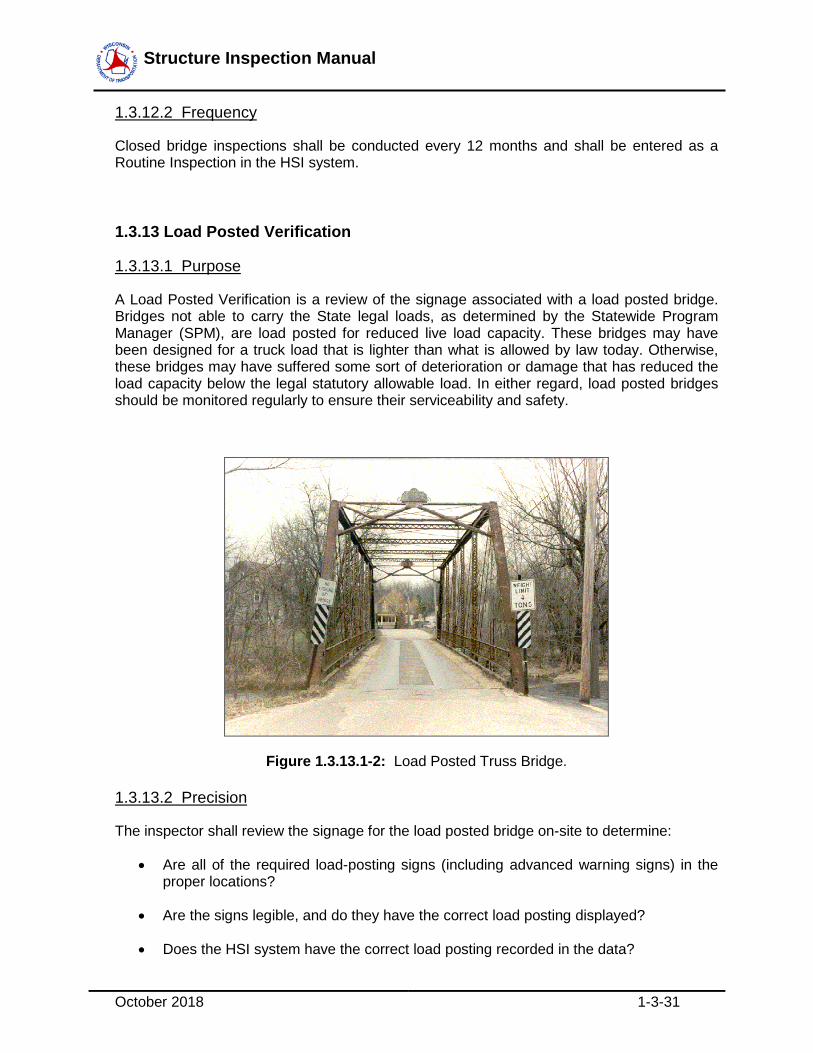
A Load Posted Verification is a review of the signage associated with a load posted bridge. Bridges not able to carry the State legal loads, as determined by the Statewide Program Manager (SPM), are load posted for reduced live load capacity. These bridges may have been designed for a truck load that is lighter than what is allowed by law today. Otherwise, these bridges may have suffered some sort of deterioration or damage that has reduced the load capacity below the legal statutory allowable load. In either regard, load posted bridges should be monitored regularly to ensure their serviceability and safety.
Figure 1.3.13.1-2: Load Posted Truss Bridge.
1.3.13.2 Precision
The inspector shall review the signage for the load posted bridge on-site to determine:
• Are all of the required load-posting signs (including advanced warning signs) in the proper locations?
• Are the signs legible, and do they have the correct load posting displayed?
• Does the HSI system have the correct load posting recorded in the data?

Structure Inspection Manual
October 2018 1-3-32
The results of the inspection should be recorded as a Load Posted Verification activity in HSI, including photos of ALL of the Signs. This type of activity does not need to be performed by certified bridge inspectors. An ITM can be sent out to perform specific inspection or measurement tasks under the direction of an Inspection Team Leader (ITL).
1.3.13.3 Frequency
This activity only needs to be performed when load postings change on the structure. When a structure is load posted, the Verification should be within 30 days of the signs being installed.
1.3.14 Deck Evaluation
1.3.14.1 Purpose
Over time, bridge decks deteriorate. Routine inspectors use various methods of inspection (both visual and audible) to detect defects in bridges decks. Often times, more in-depth methods are required to ascertain condition. Common methods employed by WisDOT include:
• Ground Penetrating Radar (Part 5, Chapter 10)
• Infrared Thermography (Part 5, Chapter 11)
• Chloride Ion testing (Part 5, Chapter 16)
When these testing methods are used, they shall be recorded in HSI under the Deck Evaluation activity and all reports from the testing shall be uploaded into the activity.
1.3.14.2 Precision
Refer to Part 5 of this manual for specifics on when to use each method.
1.3.14.3 Frequency
There is no required frequency for this activity. It is recommended prior to scoping a project on the bridge, or when the inspection TL and PM determine that it is needed to determine the condition of the deck surface when visual and/or audible methods are insufficient or potentially dangerous (due to high traffic volumes).
1.3.15 Scour Plan of Action
1.3.15.1 Purpose
The National Bridge Inspection Standards (NBIS) regulation, 23 CFR 650.313, requires that bridge owners identify bridges that are scour critical (coded 0, 1, 2, or 3 in Item 113) and to prepare a plan of action (POA) to monitor known and potential deficiencies.

Structure Inspection Manual
October 2018 1-3-33
Bridges that are scour critical require that the HSI bridge file have a POA document on file.
1.3.15.2 Precision
In general, a plan of action should focus on providing information that the inspector needs when out in the field. The plan should refer to plans, previous inspector reports, UW-Profile data, and other items pertinent to the bridge.
The POA should detail the foundation type, previous scour history, and monitoring benchmarks for the inspector to assess while in the field. It should also include a bridge closure plan that details when the bridge should be closed, who’s responsible for the closure, when the bridge can be re-opened and what detour route should be used during the closure.
1.3.15.3 Frequency
The POA document shall be updated every four calendar years or after significant flooding events. This requires a new POA activity entry into HSI.
1.3.16 Vertical Clearance Measured Activity
1.3.16.1 Purpose
The clearances on or under a bridge shall be measured periodically to determine changes in clearance that affect the mobility of Oversize/Overweight vehicle traffic.
Figure 1.3.15.1-1: Vertical Clearance Photo

Structure Inspection Manual
October 2018 1-3-34
1.3.16.2 Precision
Clearances should be taken in every lane, at edge of lanes, edge of paved shoulders, and at barrier edges to determine the low point for vehicular travel.
1.3.16.3 Frequency
This activity shall be completed every time there is a construction project on or under a bridge. In addition, after a bridge is hit the inspector conducting the damage inspection should determine if they need to re-measure clearances and if so, enter a vertical clearance verification along with the damage report.
1.3.17 Critical Findings Activity
1.3.17.1 Purpose
A critical finding is defined by WisDOT as “A bridge or portion thereof, discovered either by bridge inspection or notification by the public, which critically threatens the structyural stability of the bridge and/or the public safety, and is of such severity that immediate partial or full closure of the structure may be warranted”. See Part 1, Chapter 7 for more details.
Figure 1.3.16.1-1: Critical Finding Photo
Structure Inspection Manual
October 2018 1-3-35
1.3.17.2 Precision
When the severity of the finding is deemed Urgent or Severe (as defined by Part 1, Chapter 7), a critical findings activity shall be entered into HSIS with a completed DT2026 form attached.
1.3.17.3 Frequency
This activity is entered into the HSI System on an as-needed basis.