
STRUCTURE GEOTECHNICAL REPORT …...STRUCTURE GEOTECHNICAL REPORT LONGMEADOW PARKWAY OVER FOX RIVER...
95
STRUCTURE GEOTECHNICAL REPORT LONGMEADOW PARKWAY OVER FOX RIVER SN: 045-3024 STATION 2210+35.40 KANE COUNTY DIVISION OF TRANSPORTATION ILLINOIS For McDonough Associates, Inc. 130 East Randolph Street, Suite 1000 Chicago, IL 60601 (312) 946-8600 By Wang Engineering, Inc. 1145 North Main Street Lombard, IL 60148 (630) 953-9928 August 21, 2012 WEI Ref. No. 201-23-01 Fox River Bridge
Transcript of STRUCTURE GEOTECHNICAL REPORT …...STRUCTURE GEOTECHNICAL REPORT LONGMEADOW PARKWAY OVER FOX RIVER...
STRUCTURE GEOTECHNICAL REPORT
LONGMEADOW PARKWAY OVER FOX RIVERSN: 045-3024
STATION 2210+35.40
KANE COUNTY DIVISION OF TRANSPORTATIONILLINOIS
For
McDonough Associates, Inc.
130 East Randolph Street, Suite 1000
Chicago, IL 60601
(312) 946-8600
By
Wang Engineering, Inc.
1145 North Main Street
Lombard, IL 60148
(630) 953-9928
August 21, 2012
WEI Ref. No. 201-23-01 Fox River Bridge
Technical Report Documentation Page
‘K—r WnqEngineering
1. Title and Subtitle 2. Report Date
Structure Geotechnical Report August 21, 2012Longmeadow Parkway Bridge Corridor
3. Report Type SGR 0 RGRLongmeadow Parkway over Fox River Q Draft Final Q Revised
4. Route! Section / County 5. IDOT Job / Contract No.Longmeadow Parkway! 94-00215-01 -ES / Kane Job No. P-9 1 -3 93-94
Contract6. PTB / Item No. 5. Existing Structure Number(s) 6. Proposed Structure Number(s)
N/A N/A SN. 045-30247. Prepared by Contributor(s) Contact Phone Number
Wang Engineering, Inc. Author: Mohammed Kothawala, P.E. (630) 953-9928 ext 361 145 N Main Street QC/QA: Jerry W.H. Wang, PhD, P.E.Lombard. IL 60148 PM: Mohammed Kothawala, P.E.
9. Prepared for Design / Structural Engineer Contact Phone NumberMcDonough Associates, Inc. Gerald E. Koylass, S.E. (312) 946-8600130 East Randolph StreetSuite 1000Chicago, IL 60601
10. Abstract
A new bridge will be constructed over Fox River as part of the new Longmeadow Parkway BridgeCorridor. This report provides geotecimical recommendations for the design and construction of theproposed bridge structure. The bridge structure will be 1307’-3” long back-to-back abutments with 8spans. Wang obtained 18 structure borings, 2 at each substructure.
On the western bank of the Fox River, the soils generally encountered 6 inches to 4.5 feet of darkbrown to black silty clay loam topsoil followed by 2.5 to ii feet of loose to very dense, gravelly sandwith cobbles overlies medium stiff to hard, brown and gray, clay loam, with occasional lenses of sandand interbedded layers of sandy clay. Bedrock was encountered at approximate elevation 658 feetNGVD.
On the eastern bank of the Fox River, the soils generally encountered 4 to 18 inches of brown to blackloam, silty loam, and silty clay loam topsoil followed by very loose to medium dense silty loam toloam, very soft to hard silty clay to silty clay loam, and very soft sandy clay ranging in thickness of 4to 8.5 feet. Loose to very dense, gravelly sand to sand ranging from 2.5 to 32.5 feet thick followed bystiff to hard, clay loam extend to boring termination depth or auger refusal on weathered bedrock.Bedrock was encountered between elevation 656 feet and 661 feet NGVD.
The proposed bridge structure is recommended to be supported on H-piles. There will not bedowndrag loads. The report provides pile design data and geotechnical soil parameters for pileanalysis under lateral load.
11. Path to archived fileS:\Neiprojects’201 2301’Report RPT_Wang_MAK_Drafl SGR Longmeadow Parkway over Fox River_201 10331 .doc
‘4V WangEngineering
TABLE OF CONTENTS
1.0 INTRODUCTION 1
2.0 PROJECT DESCRIPTION 1
3.0 EXISTING AND PROPOSED STRUCTURE 2
4.0 PURPOSE AND SCOPE 2
5.0 GEOLOGIC SETTING 3
5.1 BEDROCK GEOLOGY 35.2 GLACIAL COVER 3
6.0 METHODS OF INVESTIGATION 4
6.1 SUBSURFACEINVESTIGATION 46.2 LABORATORY TESTING 5
7.0 RESULTS OF FIELD AND LABORATORY INVESTIGATIONS 5
7.1 SUBSURFACE INVESTIGATION 57.2 GROUNDWATER CONDITIONS 77.3 SEISMIC DESIGN CONSIDERATIONS 77.4 MINING ACTIVITY 8
8.0 FOUNDATION ANALYSIS AND RECOMMENDATIONS 8
8.1 APPROACH EMBANKMENT AND SLAB 88.1.1 Settlement 88.1.2 Global Stability 9
8.2 STRUCTURE FOUNDATIONS 98.2.1 Scour Considerations 108.2.2 Downdrag Loads 108.2.3 Driven Piles 118.2.4 Pile Resistance to Lateral Loads 32
8.3 STAGE CONSTRUCTION CONSIDERATIONS 33
9.0 CONSTRUCTION CONSIDERATIONS 34
9.1 SITE PREPARATION 349.2 EXCAVATION AND UTILITIES 349.3 FILLING AND BACKFILLING 349.4 EARTHWORK OPERATIONS 349.5 PILE INSTALLATION 359.6 COFFERDAM 35
10.0 QUALIFICATIONS 36
REFERENCESEXHIBITS
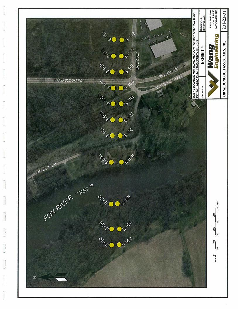
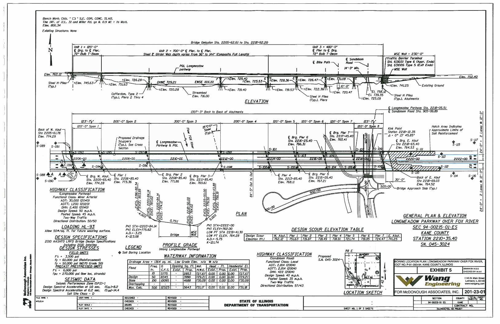
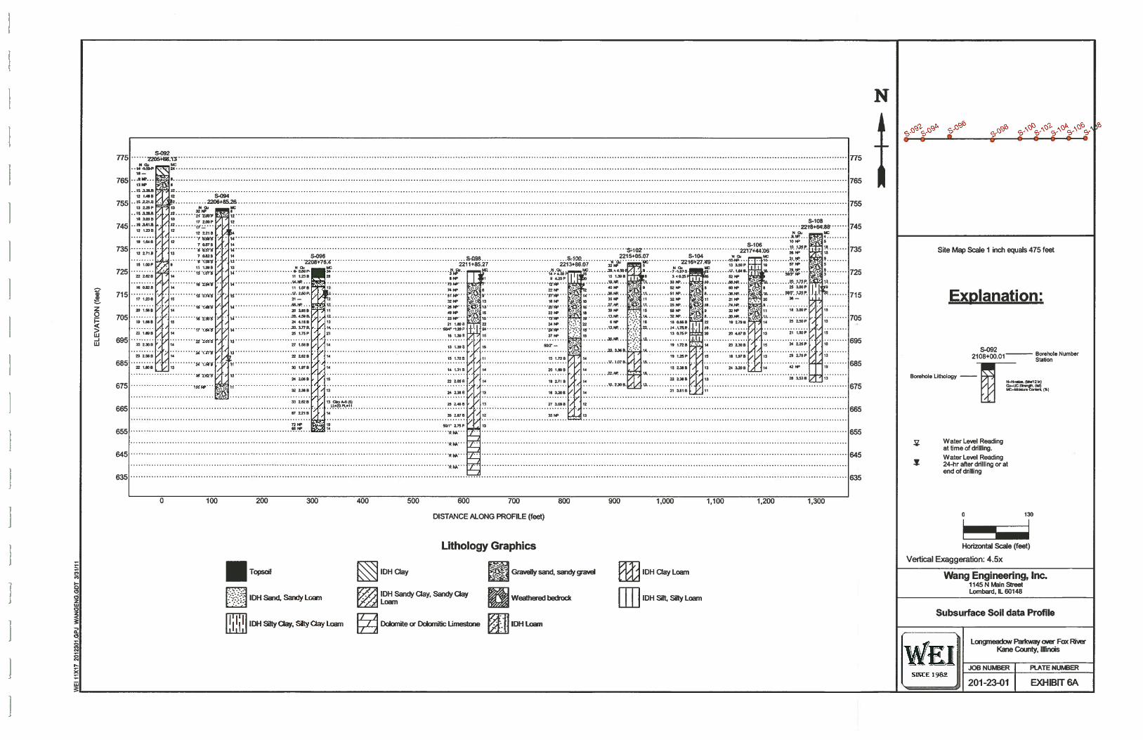
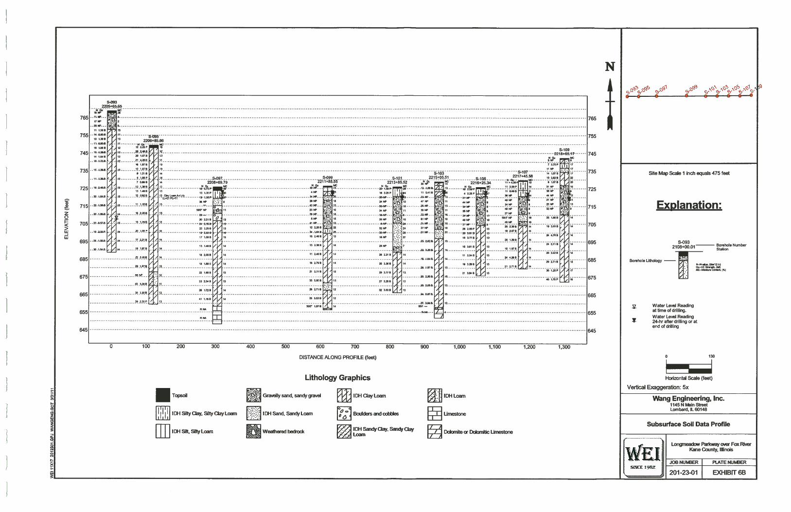
1. Project Location Map2. Site Location Map3. Site and Regional Geology4. Boring Location Map5. Boring Locations Plan6. Subsurface Soil Data Profile
APPENDIX ABoring Logs
APPENDIX BLaboratoiy Test Results
APPENDIX CGlobal Stability Analysis Results
4VWangEngineering
F1145 North Main Streetany Lombard, Illinois 60148
Engineering Phone (630) 953-9928www.wangeng.com
STRUCTURE GEOTECHNICAL REPORTLONGMEADOW PARKWAY OVER FOX RIVER
SEC 94-00215-01-ESSTATION 2210+35.40, SN: 045-3024
KANE COUNTY DIVISION OF TRANSPORTATION
FOR
MCDONOUGH ASSOCIATES INC.
1.0 INTRODUCTION
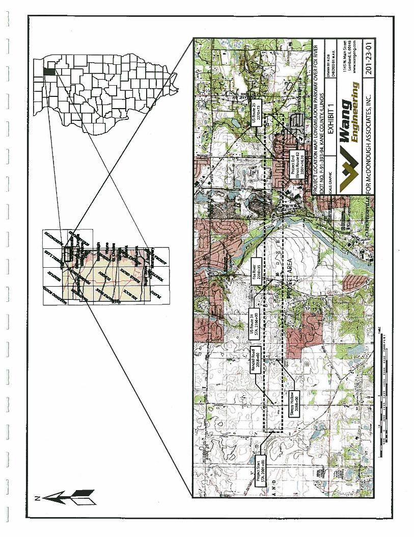
Kane County Division of Transportation planned a new access across the Fox River. This newroadway corridor referred to as “Longmeadow Parkway Bridge Corridor” extends 5.2 miles fromHuntley Road (1-mile west of Randall Road) on the west to Illinois Route 62 on the east andgenerally follows township section lines in northern Kane County. The proposed roadway willtraverse the communities of Algonquin, Carpentersville, Barrington Hills and unincorporatedKane County. The new roadway will cross Boyer Road, Randall Road, Sleepy Hollow Road,Illinois Route 31, Old Bolz Road, Illinois Route 25 and Illinois Route 62. The project corridor isshown in Exhibit 1.
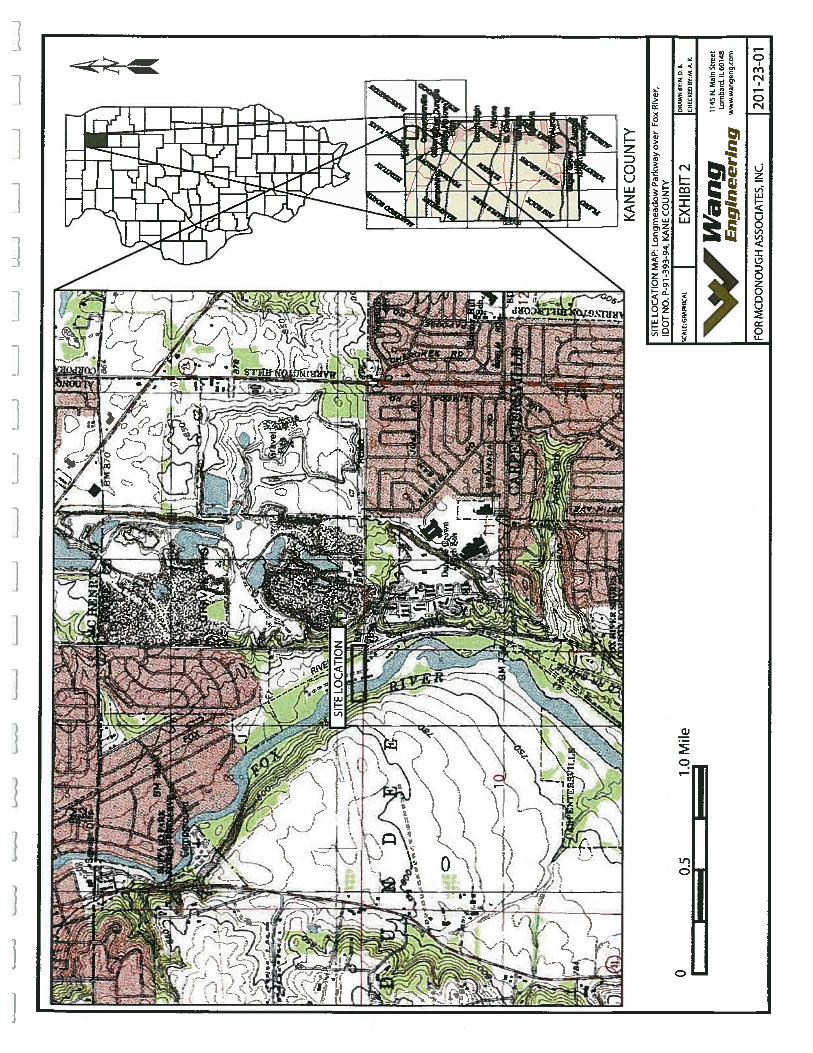
This report presents the results of Wang Engineering, Inc. (Wang) subsurface investigation,laboratory testing, and geotechnical evaluation for the proposed bridge over Fox River. Theengineering analyses and recommendations are based on DOT 2009 Bridge Manual and 2010AASHTO LRFD Bridge Design Specifications. The bridge is situated immediately northwest of thecity of Carpentersville, in Kane County, Illinois. On the USGS “Crytal lake” quadrangle Map, theproposed structure is located in the ¼ southeast of section 3 and ¼ southwest of section 2 , Tier 42North, Range 8 East. A Site Location Map is presented as Exhibit 2.
2.0 PROJECT DESCRIPTION
The project includes a new bridge over the Fox River. The proposed roadway cross-section willconsist of two-lanes in each direction separated by a landscaped median area. The median areawill be utilized at intersections as left turn lanes. Traffic signals will be installed at all majorintersection locations. Other work included in the project consists of bike path construction, openspace preservation, drainage and floodplain storage.
The following structures are included in the project.• Bridge over Fox River• Two parallel retaining walls immediately west of the bridge (Brunner property)• Two parallel retaining walls immediately east of the bridge(Carpentersville Quarry)
Geotechnical Construction EmironmenialQualiti’ Engince;-ing Services Since I 9$.?
Longmeadow Parkway Bridge CorridorLongrneadow Parkway over Fox RiverWang No. 201-23-01 Il’I1YAugust 21,2012 EngineeringPage 2
• One retaining wall west of Illinois Route 31 (Lathrop property), and• One retaining wall immediately west of Sleepy Hollow Road.
This Structure Geotechnical report (SGR) addresses the investigation and recommendations forthe Bridge over Fox River. The SGR for other structures will be prepared separately.
3.0 EXISTING AND PROPOSED STRUCTURE
There are no existing highway structures at or nearby proposed bridge location. There is noexisting subsurface information available. Based on the drawings provided by McDonoughAssociates, Inc. (MAT), the proposed bridge begins at approximately Station 2205+62.6 1 (WestAbutment) and ends at Station 2218+62.20 (East Abutment). The proposed bridge will be a 8-span structure with three units. Units 1 (Span 1 on the west side) and Unit 3 (Spans 5 through 8on the east side) will have prestressed concrete 72-inch bulb-T beams and Unit 2 (Spans 2through 4 in the middle) will have steel plate girders with web depths varying from 96-inch to144-inch; with cast-in-place concrete deck. The bridge will carry four 12-foot lanes in eachdirection with a 6-foot sidewalk and 10-foot wide bikeway on outside shoulders as well as a 4-foot median. The structure will be 84’-S” back of curb to back of curb and 1307’-3” long back-to-back abutments. The structure will require three spans to cross the Fox River. Two piers willbe located in the river. Both the abutments and piers 1, 3, 4, 5 and 7 are expansion type and piers2 and 6 will be fixed. The abutments are proposed to be stub type abutments. The span lengthsmeasured along the Proposed Grade Line (PGL) and the substructure locations are shown inExhibit 5, Boring Location Plan.
The preliminary estimated substructure LRFD factored loads were not available at the time ofreport.
4.0 PURPOSE AND SCOPE
The purpose of our investigation was to determine the subsurface soil and groundwater levelconditions within this project area that would form a basis for foundation and earthwork designrecommendations. Specifically, the scope of the investigation was as follows:• To investigate by means of exploratory borings, the subsurface soils and ground water level
conditions at the site to depths that will be influenced by the proposed construction;• To evaluate from laboratory tests, the physical properties of the soils and rocks underlying
the site that will influence foundation design and construction;• To provide recommendations and data for the design and installation of foundations,
including the suitable foundation type or types, bearing capacity, the elevation or elevationsat which the foundations should be established, and the estimated foundation settlement;
• To provide recommendations relative to construction operations and special designtechniques that may be required; and
• To provide a report summarizing the results of our studies, conclusions, and
Longmeadow Parkway Bridge CorridorLongrneadow Parkway over Fox RiverWang No. 201-23-01 I’VaflgAugust 21,2012 EnqineerinPage 3
recommendations.
5.0 GEOLOGIC SETTING
The project area is located in the northeastern part of Kane County, in the communities ofAlgonquin, Carpentersville, South Barrington, and unincorporated Kane County. On the USGS“Crystal Lake” and “Barrington” quadrangle maps, the investigated area runs west to east acrossthe southern portion of sections 1 through 5 and northern portion of sections 7 through 12 of T42 N, R 8 E (see Exhibit 1).
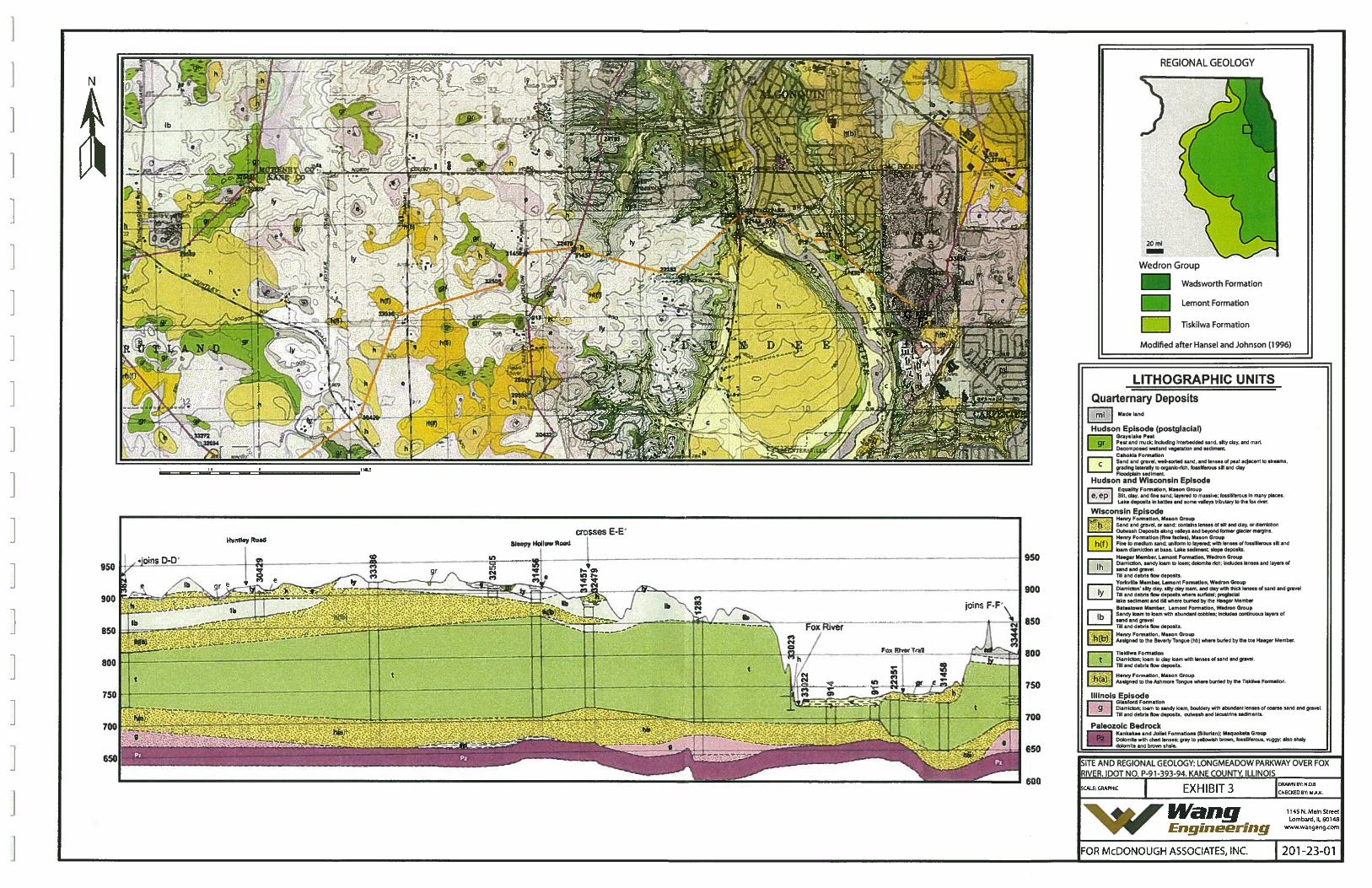
The following review of the published geologic data is meant to place within a regionalframework the results of our subsurface investigation and, thus, to confirm their generalreliability. For the study of the regional geologic framework, Wang considered northeasternIllinois area in general and northeastern Kane County in particular. The maps in Exhibit 3illustrate the Site and Regional Geologj.’.
5.1 Bedrock Geology
The bedrock surface represents a significant unconformity in Kane County. Roughly 400 millionyear old bedrock is buffed below younger glacial drift deposited less than 500,000 years ago.The uppermost bedrock unit in the area consists of nearly horizontal Silurian and Ordovician agedolomites (Curry, 2005, Dey et al., 2004). The Ordovician age dolomites tend to be softer andshaly where as the Silurian age dolomites tend to be harder. The bedrock top in the project arealies at about 620 to 680 feet elevation (NGDV) (Curry, 2005).
5.2 Glacial Cover
During the Michigan Subepisode (26,000 to 11,000 B.P.) of the Wisconsin glaciation, at thesouthern fringe of the Laurentide Ice Sheet, the Lake Michigan lobe extended over northeasternand north-central Illinois (Hansel and Johnson, 1996). Multiple advances and retreats of theglacial ice created a series of arcuate end moraine ridges consisting of glacial till. Meltwaterfrom the glaciers carried and deposited sand and gravel within, along, and away from themoraines as outwash till. In low areas, meltwater deposited free grained lake deposits.
The project site is located along the generally north to south trending Barlina Moraine to the westand the Woodstock Moraine to the east. The Barlina Moraine contains deposits of diamicton andsorted sediments associated with the Yorkville Member and Batestown Member of the LemontFormation intercalated with lenses and layers of sorted sands and gravels of the Henry Formationoverlying thick deposits of the Tiskilwa Formation. Multiple advances and retreats of the icefront in the area account for the layers in the moraine. The Woodstock Moraine contains depositsassociated with the Haeger Member of the Lemont Formation intercalated with Henry Formationdeposits overlying thick deposits of the Tiskilwa Formation.
Longmeadow Parkway Bridge CorridorLongmeadow Parkway over Fox RiverWang No. 201-23-01 IVaiigAugust 21,2012 EngineeringPage 4
Descriptions of the various formations and members (Hansel and Johnson, 1996, Dey et al.,2004, and Curry, 1995):
• Haeger Member (Lemont Formation) diamicton is light gray to gray, calcareous, and coarsetextured (sandy loam) with lenses of sand, gravel, silt, and clay.
• Batestown Member (Lemont Formation) diamicton is dark gray to gray (brown to olivebrown when oxidized), friable (when dry), sandy to silty loam and loam and containsabundant interbeds of sand and gravel.
• The Yorkville Member (Lemont Formation) diamicton is gray, fine-grained silty clay to siltyclay loam and contains lenses of sand and gravel.
• The Henry Formation contains layered sands and gravels with lenses of silt and clay.• The Tiskilwa Formation is a reddish-brown to gray medium textured (clay loam to loam)
diamicton, and contains a matrix texture of clay loam to loam.
The moraines are separated by the lower lying Fox River Valley (see Exhibit 3). Large volumesof meltwater associated with the deposition of the Woodstock Moraine eroded portions of theBarlina Moraine to the west and the underlying Tiskilwa Formation to widen the present day FoxRiver Valley. This meltwater deposited thick accumulations of sand and gravel outwash (HenryFormation) in the form of terraces and point bars.
Subsequent retreat of the glacial front to the east resulted thin accumulations of wind-blown silts(bess) on the moraines. Numerous kettles that were present on the Barlina and WoodstockMoraines were filled in with fine grained sands and silt. Periodic flooding along the Fox Riverdeposited organic rich, fine grained sediments associated with the Cahokia Formation (Dey et al.,2004 and Curry, 2005).
Our subsurface investigation results fit into the local geologic context. The borings drilled in theproject area revealed that the native sediments at the project site consist of brown (weathered) togray clayey diamicton with sand and silt lenses and thick accumulations of sand and graveloutwash deposits.
6.0 METHODS OF INVESTIGATION
6.1 Subsurface Investigation
Our subsurface investigation consisted of 18 structure borings, S-092 through S-109, drilledbetween April 19, 2005 and July 11, 2005. The borings were drilled to depths ranging from 50 to90 feet below ground surface (bgs). Boring locations are shown in Exhibits 4 and 5. The boringlocations were stacked in the field by Engineering Enterprises, Inc. (EEl, subconsultant toMcDonough Associates, Inc.) based on the plans provided by the Design Consultant, MAI.
Longmeadow Parkway Bridge CorridorLongmeadow Parkway over Fox RiverWang No. 201-23-01 IVdiigAugust 21.2012 EngineeringPage 5
There was no existing subsurface soil data available during this investigation.
An All Terrain Vehicle (ATV) -mounted drilling rig, equipped with hollow stem augers, wasused to advance and maintain an open borehole. Soil sampling was performed according toAASHTO T 206-87, “Penetration Test and Split Barrel Sampling of Soils.” The soil wassampled at 2.5 feet intervals to a depth of 30 feet and at 5-foot interval thereafter. Samplescollected from each sampling interval were placed in sealed glass jars. Below the refusal depth, rockcoring was performed in Borings S-097, S-098, and S-103, using NX-size coring equipment.
The drilling operations were supervised by a Wang field geologist/engineer, who classified thesoils and rock encountered in the borings, maintained a field log of borings, and obtained soilsamples for later visual examination and laboratory testing. He also supervised the standardpenetration tests and recorded the results of the rock coring operations. The unconfinedcompressive strengths of cohesive soil samples were obtained using Rimac Spring Tester. Thefield logs were reviewed and edited based on reexamination of the soil samples and rock cores inour laboratory.
Stations and offsets for the boring locations were also provided by EEl. Some of the boringswere relocated in the field by Wang from their originally intended locations due to the accessproblem or refusal encountered at shallower depth. As-drilled boring locations and elevations areincluded in the boring logs (Appendix A) and on the soil profiles (Exhibits 6A and 6B). Rockcore photographs for each run are also included in Appendix A.
Groundwater elevations were measured while drilling and at completion of each boring. At eachboring location, the boreholes were backfilled with soil cuttings and bentonite chips uponcompletion and the surface was restored as much as possible to its original condition.
6.2 Laboratory Testing
Soil samples and rock cores obtained by Wang in the field were transported to our in-houselaboratory in Lombard, Illinois. The testing program included water content (AASHTO T 265-93),particle-size analysis (AASHTO T 8 8-97), and Atterberg limits (AASHTO T 89-96 and AASHTOT 90-96) determinations. The samples were classified according to the AASHTO system. Theresults of laboratory testing are presented on the attached boring logs, the laboratory testworksheets and on the soil profiles.
7.0 RESULTS OF FIELD AND LABORATORY INVESTIGATIONS
7.1 Subsurface Investigation
Detailed descriptions of the subsurface conditions encountered in the borings are presented on theattached boring logs (Appendix A) and soil profiles (Exhibit 6A and 6B). Please note that the strata
Longmeadow Parkway Bridge CorridorLongmeadow Parkway over Fox RiverWang No. 201-23-01 I$’flgAugust 21,2012 EngineeringPage 6
contact lines shown on logs and profiles represent approximate boundaries between soil types. Theactual transition between soil types in the field may be different in horizontal and vertical directions.
Borings S-092 through S-097 were drilled on the western bank of the Fox River whereas BoringsS-098 through S-109 were drilled along the eastern bank of the Fox River. All borings weredrilled from existing ground elevations.
Fox River Western BankGenerally, the soils encountered on the western bank of the Fox River consisted of 6 inches to 4feet of dark brown to black silty clay loam topsoil. Below the topsoil, 2.5 to 11 feet of loose tovery dense, gravelly sand with cobbles overlies medium stiff to hard, brown and gray, clay loam,with occasional lenses of sand and interbedded layers of sandy clay. Borings S-092, S-93 and S95 terminated in the clay loam. Borings S-094 and S-096 terminated in very dense, gravelly sandor weathered bedrock. Boring S-097 encountered auger refusal at 67.5 feet bgs.
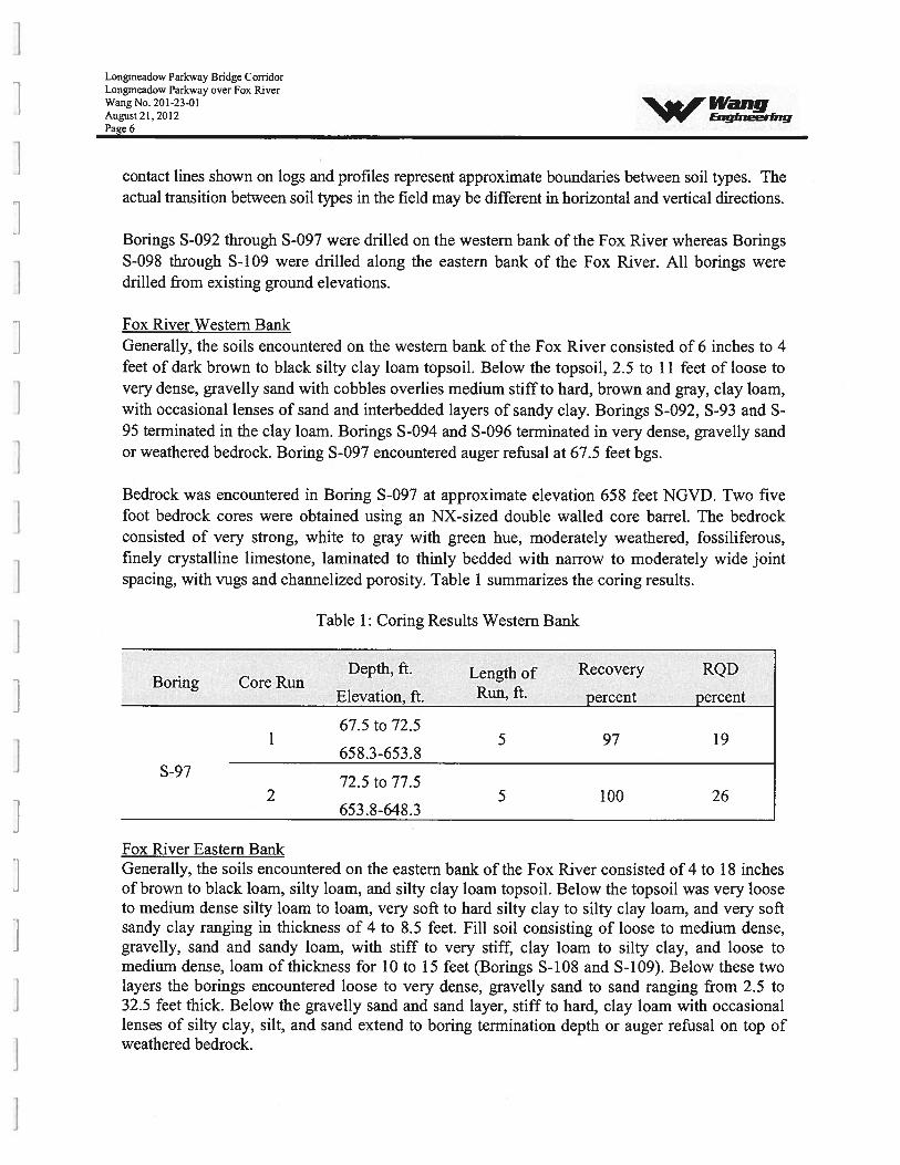
Bedrock was encountered in Boring S-097 at approximate elevation 658 feet NGVD. Two fivefoot bedrock cores were obtained using an NX-sized double walled core barrel. The bedrockconsisted of very strong, white to gray with green hue, moderately weathered, fossiliferous,finely crystalline limestone, laminated to thinly bedded with narrow to moderately wide jointspacing, with vugs and channelized porosity. Table 1 summarizes the coring results.
Table I: Coring Results Western Bank
Depth, ft. Length of Recovery RQDBoring Core Run
Elevation, ft. Run, ft. percent percent
67.5 to 72.51 5 97 19
658.3-653.8S-97
72.5 to 77.52 5 100 26
653 .8-648.3
Fox River Eastern BankGenerally, the soils encountered on the eastern bank of the Fox River consisted of 4 to 18 inchesof brown to black loam, silty loam, and silty clay loam topsoil. Below the topsoil was very looseto medium dense silty loam to loam, very soft to hard silty clay to silty clay loam, and very softsandy clay ranging in thickness of 4 to 8.5 feet. Fill soil consisting of loose to medium dense,gravelly, sand and sandy loam, with stiff to very stiff, clay loam to silty clay, and loose tomedium dense, loam of thickness for 10 to 15 feet (Borings S-108 and S-109). Below these twolayers the borings encountered loose to very dense, gravelly sand to sand ranging from 2.5 to32.5 feet thick. Below the gravelly sand and sand layer, stiff to hard, clay loam with occasionallenses of silty clay, silt, and sand extend to boring termination depth or auger refusal on top ofweathered bedrock.
Longmeadow Parkway Bridge CorridorLongmeadow Parkway over Fox RiverWang No. 201-23-0! 14”dflgAugust 21,2012 EngineerrngPage 7
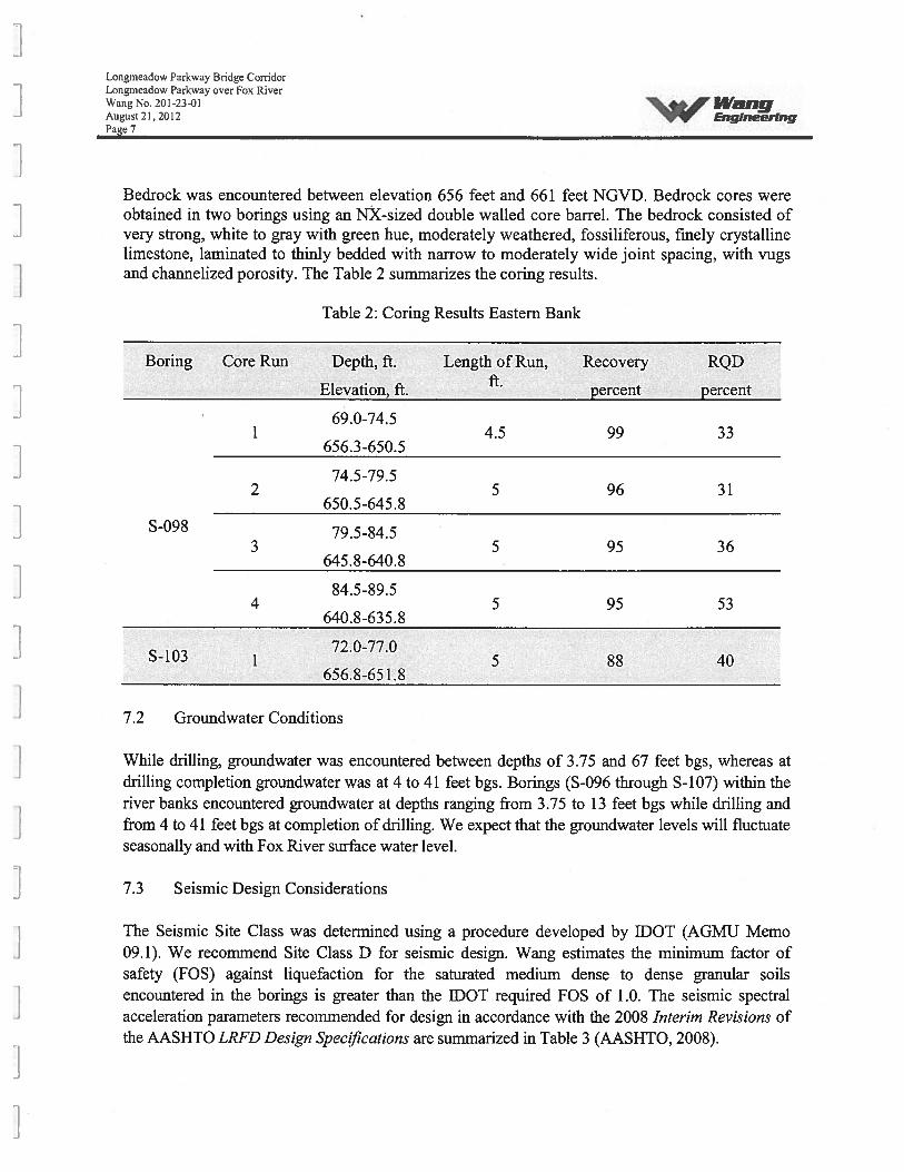
Bedrock was encountered between elevation 656 feet and 661 feet NGVD. Bedrock cores wereobtained in two borings using an NX-sized double walled core barrel. The bedrock consisted ofvery strong, white to gray with green hue, moderately weathered, fossiliferous, finely crystallinelimestone, laminated to thinly bedded with narrow to moderately wide joint spacing, with vugsand channelized porosity. The Table 2 summarizes the coring results.
Table 2: Coring Results Eastern Bank
Boring Core Run Depth, ft. Length of Run, Recovery RQD. ft.Elevation, ft. percent percent
69.0-74.51 4.5 99 33
656.3-650.5
74.5-79.52 5 96 31
650.5-645.8S-098 79.5-84.5
3 5 95 36645.8-640.8
84.5-89.54 5 95 53
640.8-635.8
72.0-77.0S-103 1 5 88 40
656.8-651.8
7.2 Groundwater Conditions
While drilling, groundwater was encountered between depths of 3.75 and 67 feet bgs, whereas atdrilling completion groundwater was at 4 to 41 feet bgs. Borings (S-096 through S-107) within theriver banks encountered groundwater at depths ranging from 3.75 to 13 feet bgs while drilling andfrom 4 to 41 feet bgs at completion of drilling. We expect that the groundwater levels will fluctuateseasonally and with Fox River surface water level.
7.3 Seismic Design Considerations
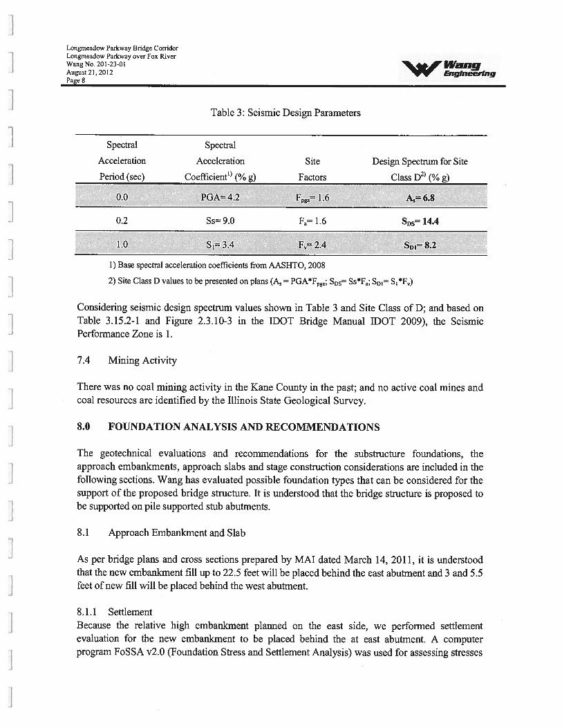
The Seismic Site Class was determined using a procedure developed by DOT (AGMJJ Memo09.1). We recommend Site Class D for seismic design. Wang estimates the minimum factor ofsafety (FOS) against liquefaction for the saturated medium dense to dense granular soilsencountered in the borings is greater than the IDOT required FOS of 1.0. The seismic spectralacceleration parameters recommended for design in accordance with the 2008 Interim Revisions ofthe AASHTO LRFD Design Spec!Ications are summarized in Table 3 (AASHTO, 2008).
Longmeadow Parkway Bridge CorridorLongrneadow Parkway over Fox RiverWang No. 201-23-01 IVngAueust 21,2012 EnqineerfngPage 8
Table 3: Seismic Design Parameters
Spectral Spectral
Acceleration Acceleration Site Design Spectrum for Site
Period (sec) Coefficient (% g) Factors Class D2 (% g)
0.0 PGA” 4.2 Fpga= 1.6 A5 6.8
0.2 Ss= 9.0 Fa 1.6 SDs 14.4
1.0 S1=3.4 F=2.4 SDI=8.2
1) Base spectral acceleration coefficients from AASHTO, 2008
2) Site Class D values to be presented on plans (A = PGA*Fpga; SDS= Ss*Fa; SD1= Si*F)
Considering seismic design spectrum values shown in Table 3 and Site Class of D; and based onTable 3.15.2-1 and Figure 2.3.10-3 in the IDOT Bridge Manual DOT 2009), the SeismicPerformance Zone is 1.
7.4 Mining Activity
There was no coal mining activity in the Kane County in the past; and no active coal mines andcoal resources are identified by the Illinois State Geological Survey.
8.0 FOUNDATION ANALYSIS AND RECOMMENDATIONS
The geotechnical evaluations and recommendations for the substructure foundations, theapproach embankments, approach slabs and stage construction considerations are included in thefollowing sections. Wang has evaluated possible foundation types that can be considered for thesupport of the proposed bridge structure. It is understood that the bridge structure is proposed tobe supported on pile supported stub abutments.
8.1 Approach Embankment and Slab
As per bridge plans and cross sections prepared by MAT dated March 14, 2011, it is understoodthat the new embanlcrnent fill up to 22.5 feet will be placed behind the east abutment and 3 and 5.5feet of new fill will be placed behind the west abutment.
8.1.1 SettlementBecause the relative high embankment planned on the east side, we performed settlementevaluation for the new embankment to be placed behind the at east abutment. A computerprogram FoSSA v2.0 (Foundation Stress and Settlement Analysis) was used for assessing stresses
Longmeadow Parkway Bridge CorridorLongrneadow Parkway over Fox RiverWang No. 201-23-01 LVaiigAugust 21,2012 EngineeringPage 9
and settlements under embankment. Soil parameters required for elastic settlement evaluation andfor consolidation settlement analysis were estimated from the soil index properties using variouswell known published correlations. We estimate settlement of the embankment at the eastabutment is on the order of 2 inches, approximately 1.1 inches from the granular soils and 0.9inches from the cohesive soils. The total settlement at the west abutment is anticipated to be lessthan 0.4 inches.
The elastic (immediate) settlement of the granular soils and consolidation (long-term) settlementof the cohesive soil layers are expected to occur. Most of the settlement is expected to beoccurring at the same rate as the construction of the embankment progresses. We estimate that byend of embankment construction at the east abutment, the remaining foundation settlement tobe about 0.4 inches. There will be negligible downdrag on the piles. We did not consider anyallowances for the downdrag loads on the piles. We recommend that the pile installation andpavement construction for the roadway should be delayed as much as possible after constructioncompletion of the approach embankment. This requirement should be included in the projectconstruction contract.
8.1.2 Global StabilityThe global stability of the side and end slopes were analyzed based on the subsurface soilconditions encountered in the borings and the slope information provided in the TSL. The sideand end slopes were considered at 3:1 (H:V) and 2:l(H:V), respectively. Analyses wereperformed with SLIDE v5 computer software. The minimum FOS calculated are 1.63 for sideslopes at the east abutment, 3.51 for the end slope and 4.39 for the side slope at the westabutment greater than the IDOT required FOS of 1.5. Therefore, we recommend a slope of2: l(H:V) or flatter with slope surface protection. Details of the Global Stability Analysis withthe critical failure surfaces and results are presented in Appendix C.
8.2 Structure Foundations
Wang has evaluated various possible foundation types that can be considered for the support ofthe proposed bridge structure. As per IDOT Bridge Manual (IDOT 2009), the completely newbridge structure should be designed following AASHTO LRFD Bridge Design Specifications.
A shallow foundation consisting of spread footing would not be suitable considering the low soilbearing capacity and potential differential settlement concern between the substructures. Due tovariable nature of the soil conditions, we do not recommend considering drilled shafts establishedin soil. Foundation system consisting of drilled shafts socketed into the bedrock can beconsidered, however, it may not be economical compare to driven piles. It is our opinion that adriven pile foundation system will be appropriate to support the substructures. The mosteconomical pile size should be selected.
Longmeadow Parkway Bridge CorridorLongmeadow Parkway over Fox RiverWang No. 201-23-01August 21,2012 EngineeringPage 10
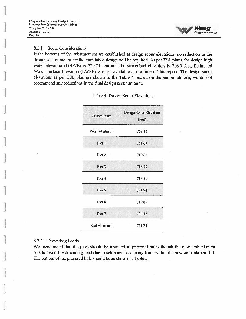
8.2.1 Scour ConsiderationsIf the bottoms of the substructures are established at design scour elevations, no reduction in thedesign scour amount for the foundation design will be required. As per TSL plans, the design highwater elevation (DHWE) is 729.21 feet and the streambed elevation is 716.0 feet. EstimatedWater Surface Elevation (EWSE) was not available at the time of this report. The design scourelevations as per TSL plan are shown in the Table 4. Based on the soil conditions, we do notrecommend any reductions in the final design scour amount.
Table 4: Design Scour Elevations
Design Scour ElevationSubstructure
(feet)
West Abutment 762.12
Pier 1 751.63
Pier 2 719.87
Pier 3 718.49
Pier4 718.91
PierS 721.74
Pier 6 719.85
Pier 7 724.47
East Abutment 741.25
8.2.2 Downdrag LoadsWe recommend that the piles should be installed in precored holes though the new embankmentfills to avoid the downdrag load due to settlement occurring from within the new embankment fill.The bottom of the precored hole should be as shown in Table 5.
Longmeadow Parkway Bridge CorridorLongrneadow Parkway over Fox RiverWang No. 201-23-01 IWngAugust 21,2012 Enqlne.eringPage 11
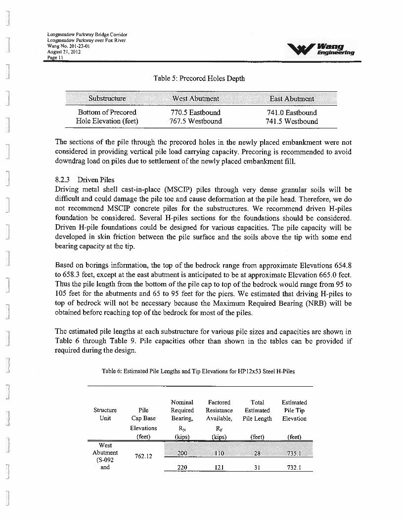
Table 5: Precored Holes Depth
Substructure West Abutment East Abutment £Bottom of Precored 770.5 Eastbound 741.0 Eastbound
Hole Elevation (feet) 767.5 Westbound 741.5 Westbound
The sections of the pile through the precored holes in the newly placed embankment were notconsidered in providing vertical pile load carrying capacity. Precoring is recommended to avoiddowndrag load on piles due to settlement of the newly placed embankment fill.
8.2.3 Driven PilesDriving metal shell cast-in-place (MSCIP) piles through very dense granular soils will bedifficult and could damage the pile toe and cause deformation at the pile head. Therefore, we donot recommend MSCIP concrete piles for the substructures. We recommend driven H-pilesfoundation be considered. Several H-piles sections for the foundations should be considered.Driven H-pile foundations could be designed for various capacities. The pile capacity will bedeveloped in skin friction between the pile surface and the soils above the tip with some endbearing capacity at the tip.
Based on borings information, the top of the bedrock range from approximate Elevations 654.8to 658.3 feet, except at the east abutment is anticipated to be at approximate Elevation 665.0 feet.Thus the pile length from the bottom of the pile cap to top of the bedrock would range from 95 to105 feet for the abutments and 65 to 95 feet for the piers. We estimated that driving H-piles totop of bedrock will not be necessary because the Maximum Required Bearing (NRB) will beobtained before reaching top of the bedrock for most of the piles.
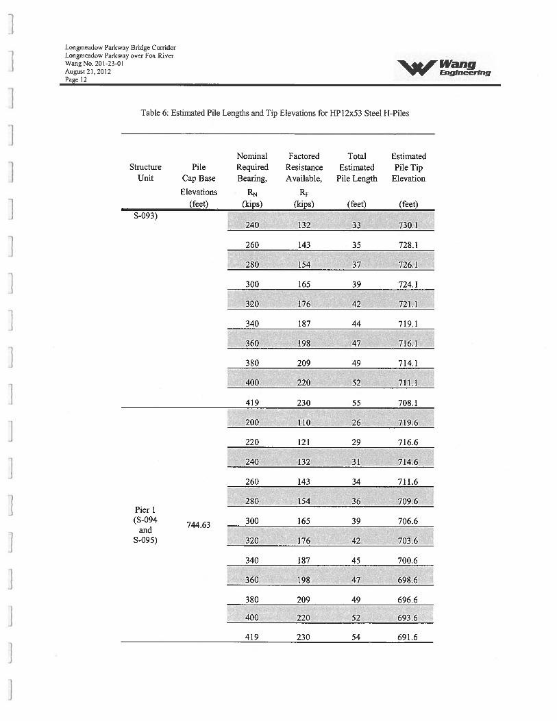
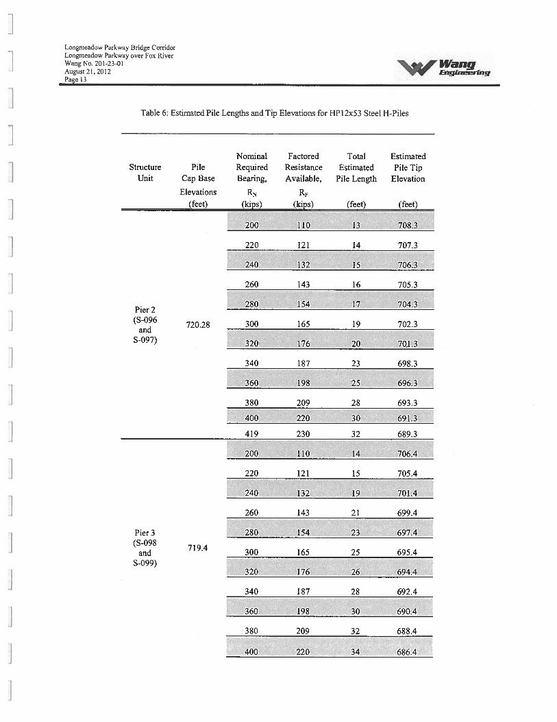
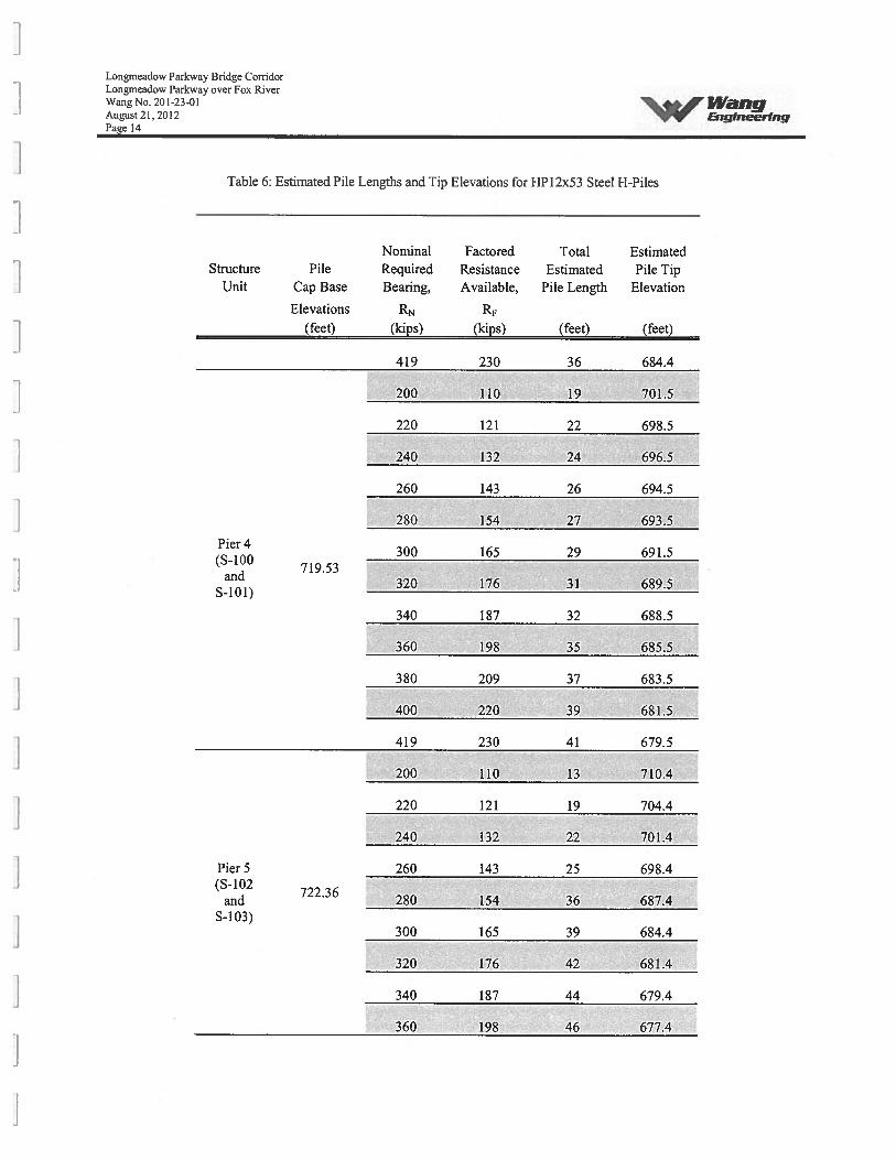
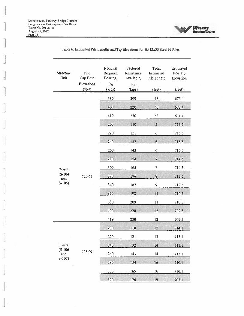
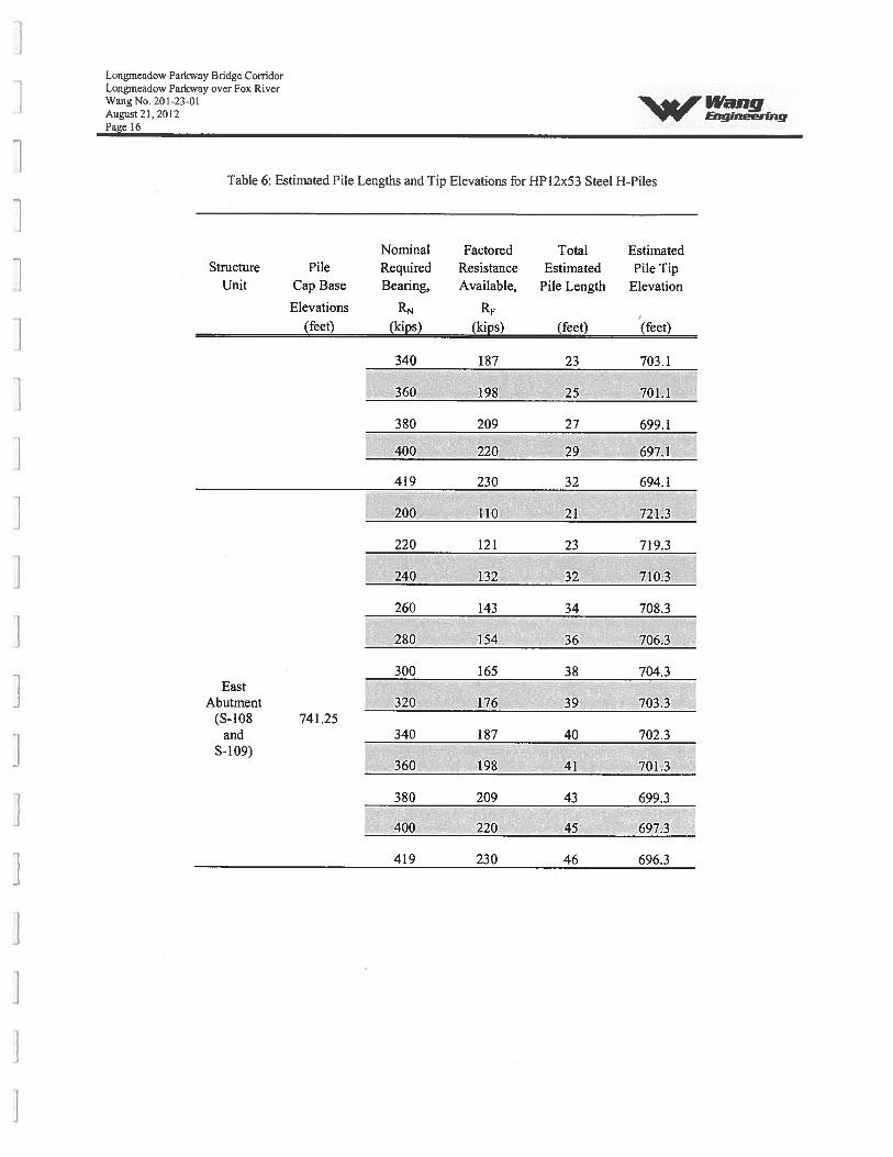
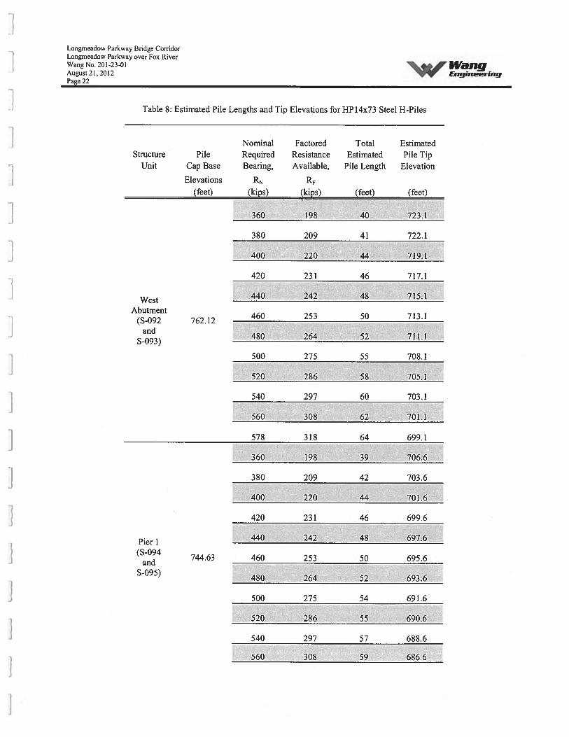
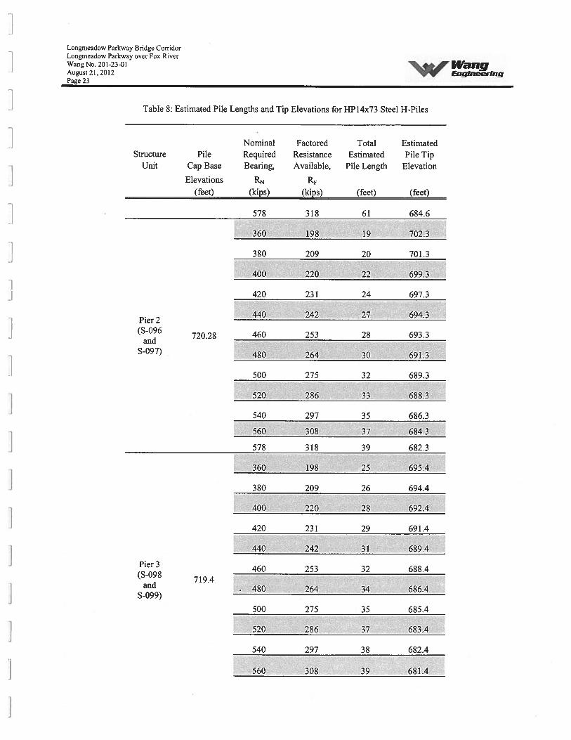
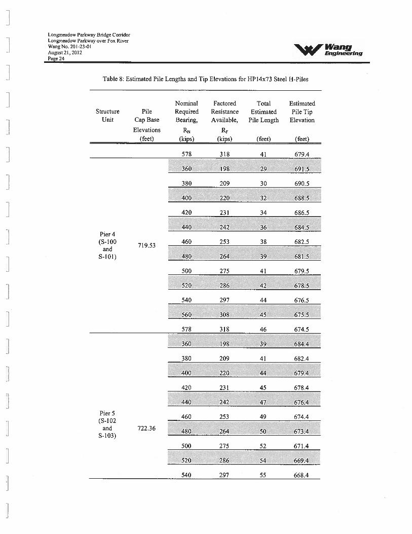
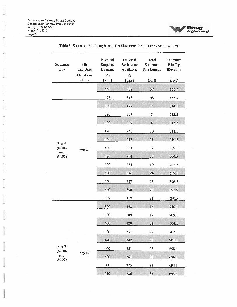
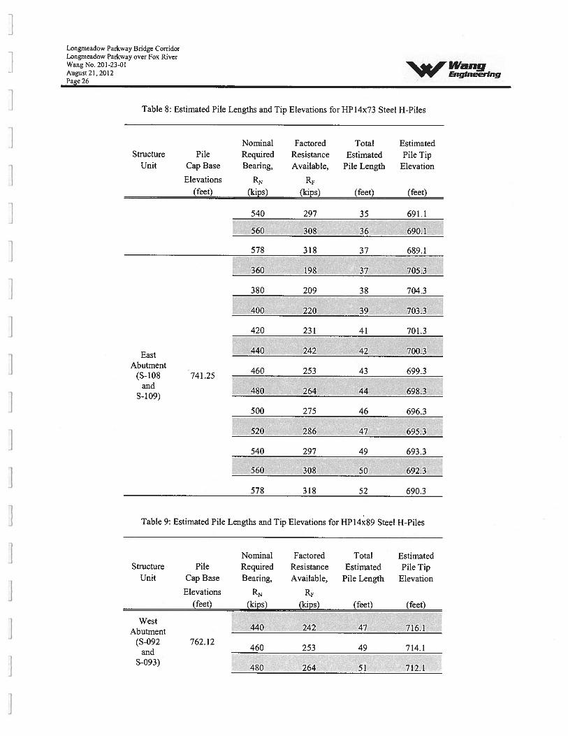
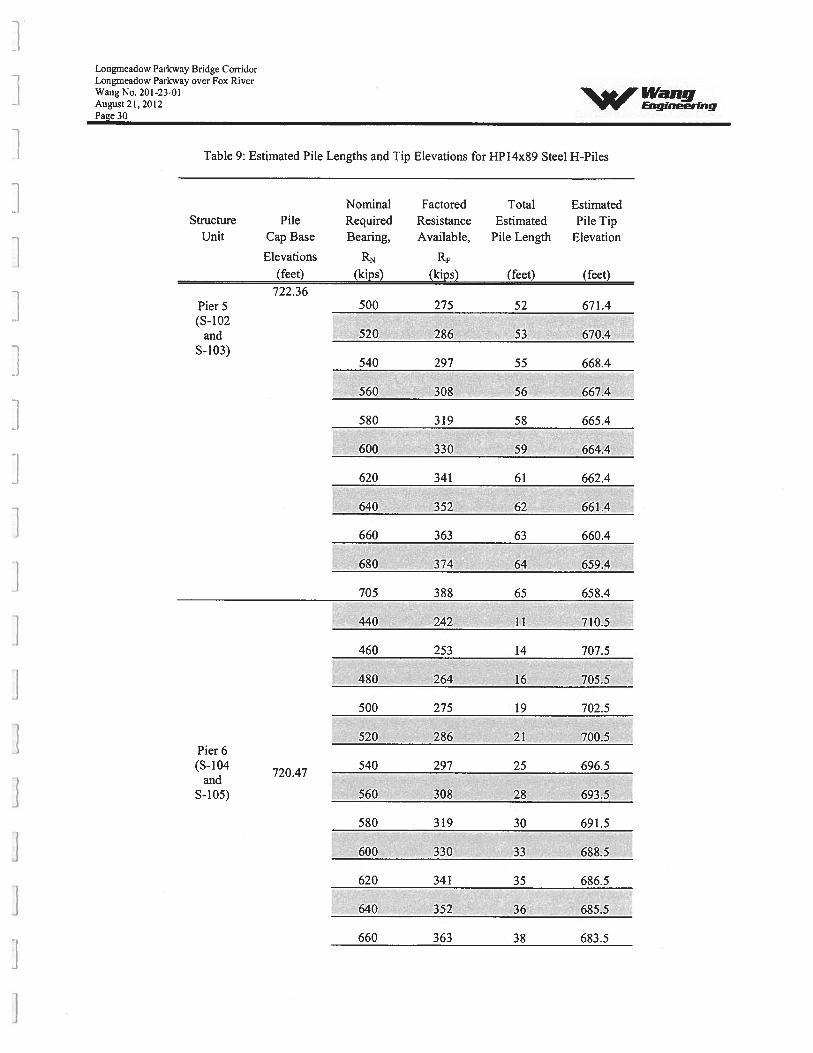
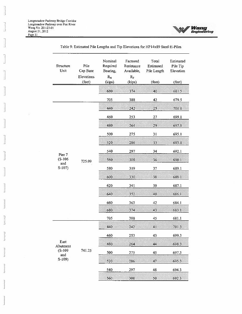
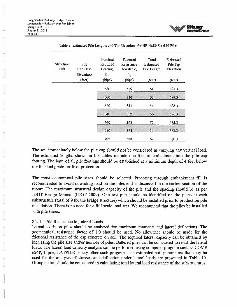
The estimated pile lengths at each substructure for various pile sizes and capacities are shown inTable 6 through Table 9. Pile capacities other than shown in the tables can be provided ifrequired during the design.
Table 6: Estimated Pile Lengths and Tip Elevations for HP12x53 Steel H-Piles
Abutment(S-092
Nominal Factored Total EstimatedStructure Pile Required Resistance Estimated Pile Tip
Unit Cap Base Bearing, Available, Pile Length Elevation
Elevations RN RF(feet) (kips) (kips) (feet) (feet)
West
762.12 200 110 28 735.1
220 121 31 732.1and
Longmeadow Parkway Bridge CorridorLongmeadow Parkway over Fox RiverWang No. 201-23-01 I’VaiigAugust 21, 2012 EngineeringPage 12
Table 6: Estimated Pile Lengths and Tip Elevations for HP12x53 Steel H-Piles
Nominal Factored Total EstimatedStnicture Pile Required Resistance Estimated Pile Tip
Unit Cap Base Bearing, Available, Pile Length Elevation
Elevations RN(feet) (kips) (kips) (feet) (feet)
S-093)240 132 33 730.1
260 143 35 728.1
280 154 37 726.1
300 165 39 724.1
320 176 42 721.1
340 187 44 719.1
360 198 47 716.1
380 209 49 714.1
400 220 52 711.1
419 230 55 708.1
200 110 26 719.6
220 121 29 716.6
240 132 31 714.6
260 143 34 711.6
280 154 36 709.6Pier 1(S-094
744.63 300 165 39 706.6and
S-095) 320 176 42 703.6
340 187 45 700.6
360 198 47 698.6
380 209 49 696.6
400 220 52 693.6
419 230 54 691.6
L.ongmeadow Parkway Bridge CorridorLongmeadow Parkway over Fox RiverWang No. 201-23-01August21, 2012Page 13
‘b4’F WangEngineering
Table 6: Estimated Pile Lengths and Tip Elevations for HP12x53 Steel H-Piles
Nominal Factored Total EstimatedStnicture Pile Required Resistance Estimated Pile Tip
Unit Cap Base Bearing, Available, Pile Length Elevation
Elevations RN RF
(feet) (kips) (kips) (feet) (feet)
Pier 2(S-096
720.28and
S-097)
200 110 13 708.3
220 121 14 707.3
240 132 15 706.3
260 143 16 705.3
280 154 17 704.3
300 165 19 702.3
320 176 20 701.3
340 187 23 698.3
360 198 25 696.3
380 209 28 693.3
400 220 30 691.3
419 230 32 689.3
200 110 14 706.4
220 121 15 705.4
240 132 19 701.4
260 143 21 699.4
280 154 23 697.4
300 165 25 695.4
320 176 26 694.4
340 187 28 692.4
360 198 30 690.4
380 209 32 688.4
400 220 34 686.4
Pier 3(S-098
andS-099)
719.4
Longmeadow Parkway Bridge CorridorLongmeadow Parkway over Fox RiverWang No. 201-23-01August 21,2012 EngineeringPage 14
Table 6: Estimated Pile Lengths and Tip Elevations for HP12x53 Steel H-Piles
Nominal Factored Total EstimatedStructure Pile Required Resistance Estimated Pile Tip
Unit Cap Base Bearing, Available, Pile Length Elevation
Elevations RN RF
(feet) (kips) (kips) (feet) (feet)
419 230 36 684.4
200 110 19 701.5
220 121 22 698.5
240 132 24 696.5
260 143 26 694.5
280 154 27 693.5
Pier4300 165 29 691.5(5- 00
719.53
S-WI)320 176 31 689.5
340 187 32 688.5
360 198 35 685.5
380 209 37 683.5
400 220 39 681.5
419 230 41 679.5
200 110 13 710.4
220 121 19 704.4
240 132 22 701.4
Pier 5 260 143 25 698.4(S-102 777 36and 280 154 36 687.4S-103)
300 165 39 684.4
320 176 42 681.4
340 187 44 679.4
360 198 46 677.4
Longmeadow Parkway Bridge CorridorLongrneadow Parkway over Fox RiverWang No, 201-23-01August 21, 20 12Page 15
‘3’,WangEngineering
Table 6: Estimated Pile Lengths and Tip Elevations for HP12x53 Steel H-Piles
Nominal Factored Total EstimatedStructure Pile Required Resistance Estimated Pile Tip
Unit Cap Base Bearing, Available, Pile Length Elevation
Elevations RN(feet) (kips) (kips) (feet) (feet)
Pier 6(S-104
andS-105)
720.47
380 209 48 675.4
400 220 50 673.4
419 230 52 671.4
200 110 5 716.5
220 121 6 715.5
715.5
260 143 6 715.5
280 154 7 714.5
300 165 7 714.5
320 176 8 713.5
340 187 9 712.5
360 198 11 710.5
380 209 11 710.5
400 220 12 709.5
419 230 709.5
200 110 12 714.1
220 121 13 713.1
240 132 14 712.1
260 143 14 712.1
280 154 16 710.1
300 165 16 710.1
320 176 19 707.1
Pier 7(S-106
andS-107)
725.09
Longmeadow Parkway Bridge CorridorLorigmeadow Parkway over Fox RiverWang No, 20 1-23-01 WdngAugust 21,2012 EngsneerrngPage 16
Table 6: Estimated Pile Lengths and Tip Elevations for HP12x53 Steel H-Piles
Nominal Factored Total EstimatedStructure Pile Required Resistance Estimated Pile Tip
Unit Cap Base Bearing, Available, Pile Length Elevation
Elevations RN RF(feet) (kips) (kips) (feet) (feet)
340 187 23 703.1
360 198 25 701.1
380 209 27 699.1
400 220 29 697.1
419 230 32 694.1
200 110 21 721.3
220 121 23 719.3
240 132 32 710.3
260 143 34 708.3
280 154 36 706.3
300 165 38 704.3East
Abutment 320 176 39 703.3(5-108 741.25
and 340 187 40 702.3S-i 09)
360 198 41 701.3
380 209 43 699.3
400 220 45 697.3
419 230 46 696.3
Lonemeadow Parkway Bridge CorridorLongmeadow Parkway over Fox RiverWangNo. 201-23-01August 21, 2012Page 17
WrWangEngineering
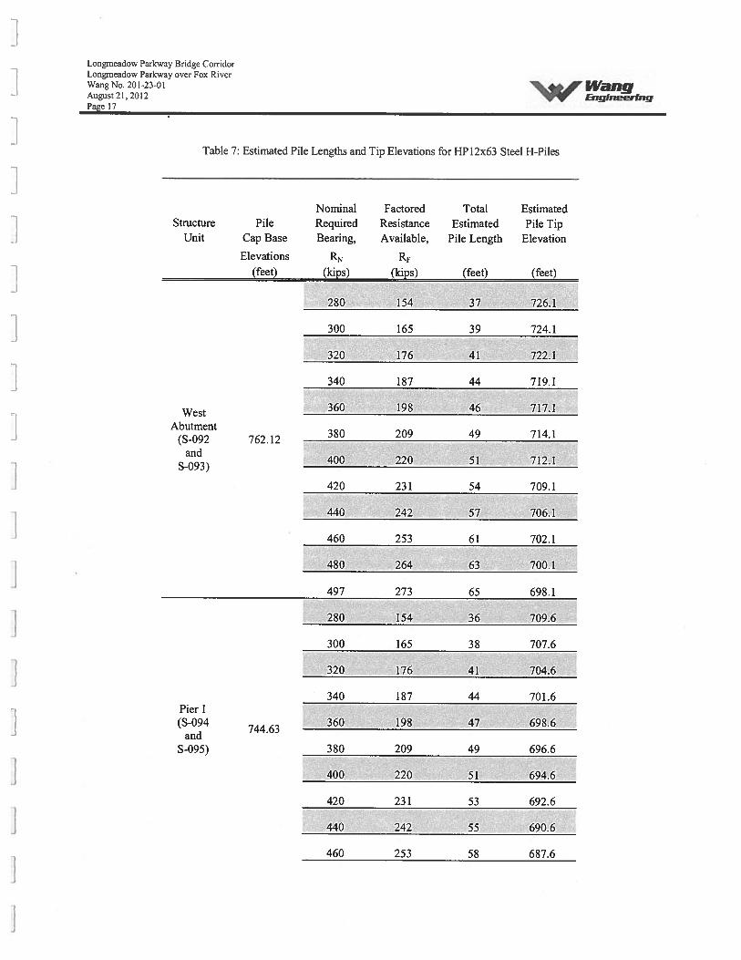
Table 7: Estimated Pile Lengths and Tip Elevations for HP12x63 Steel H-Piles
Nominal Factored Total EstimatedStructure Pile Required Resistance Estimated Pile Tip
Unit Cap Base Bearing, Available, Pile Length Elevation
Elevations RN(feet) (kips) (kips) (feet) (feet)
WestAbutment
(S-092 762.12and
S-093)
280 154 37 726.1
300 5 39 724.1
320 176 41 722.1
340 187 44 719.1
360 8 46 717.1
380 209 49 714.1
400 220 712.1
420 231 54 709.1
440 242 57 706.1
460 253 702.1
480 264 63 700.1
497 273 65 698.1
280 154 36 709.6
300 165 38 707.6
320 176 41 704.6
340 187 44 701.6
360 198 47 698.6
380 209 49 696.6
400 220 51 694.6
420 231 53 692.6
440 242 55 690.6
460 253 58 687.6
Pier 1(S-094
andS-095)
744.63
Longmeadow Parkway Bridge CorridorLougmeadow Parkway over Fox RiverWang No. 201-23-01 i4’ngAugust 21,2012Page 18
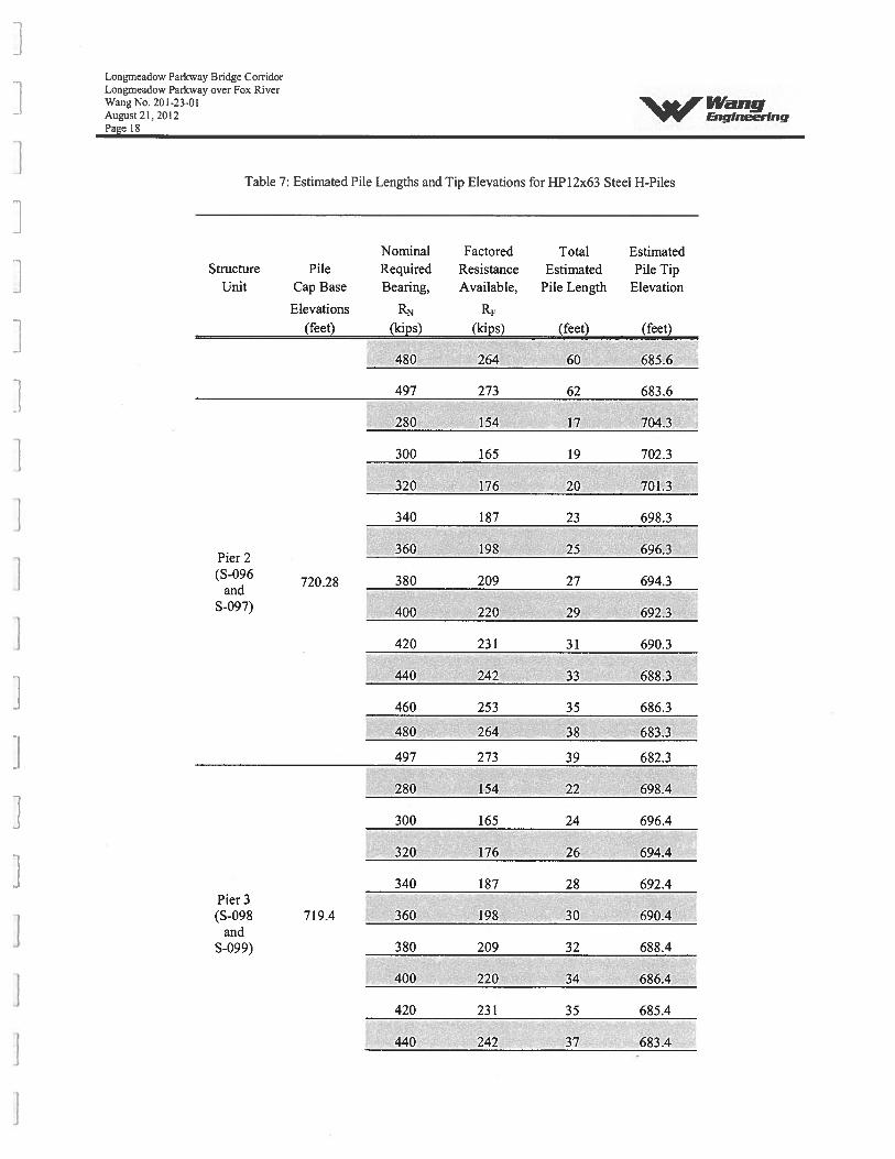
Table 7: Estimated Pile Lengths and Tip Elevations for HP12x63 Steel I-I-Piles
Nominal Factored Total EstimatedStructure Pile Required Resistance Estimated Pile Tip
Unit Cap Base Bearing, Available, Pile Length Elevation
Elevations RN RF(feet) (kips) (kips) (feet) (feet)
480 264 60 685.6
497 273 62 683.6
280 154 17 704.3
300 165 19 702.3
320 176 20 701,3
340 187 23 698.3
360 198 25 696.3Pier 2(S-096
720.28 380 209 27 694.3and
S-097) 400 220 29 692.3
420 231 31 690.3
440 242 33 688.3
460 253 35 686.3
480 264 38 683.3
497 273 39 682.3
280 154 22 698.4
300 165 24 696.4
320 176 26 694,4
340 187 28 692.4Pier 3(S-098 719.4 360 198 30 690.4
andS-099) 380 209 32 688.4
400 220 34 686.4
420 231 35 685.4
440 242 37 683.4

Longmeadow Parkway Bridge CorridorLongmeadow Parkway over Fox RiverWang No. 201-23-01 IVaflgA’ueust 21, 2012 EngineerrngPage 19
Table 7: Estimated Pile Lengths and Tip Elevations for HPl2x63 Steel H-Piles
Nominal Factored Total EstimatedStructure Pile Required Resistance Estimated Pile Tip
Unit Cap Base Bearing, Available, Pile Length Elevation
Elevations RN RF
(feet) (kips) (kips) (feet) (feet)
460 253 38 682.4
480 264 40 680.4
497 273 41 679.4
280 154 27 693.5
300 165 29 691.5
320 176 30 690.5
340 187 32 688.5
360 198 34 686.5Pier 4(S-l00
719.53380 209 37 683.5
andS-lOl) 400 220 39 681.5
420 231 41 679.5
440 242 42 678.5
460 253 44 676.5
480 264 46 674.5
497 273 47 673.5
280 154 35 688.4
300 165 38 685.4
320 176 41 682.4
Pier 5 340 187 44 679.4(S-102
722.36
S-l03)360 198 46 677.4
380 209 48 675.4
400 220 50 673.4
Longmeadow Parlcway Bridge CorridorLongrneadow Parkway over Fox RiverWang No. 201-23-01August21, 2012Page 20
“WrWang -E,isneering
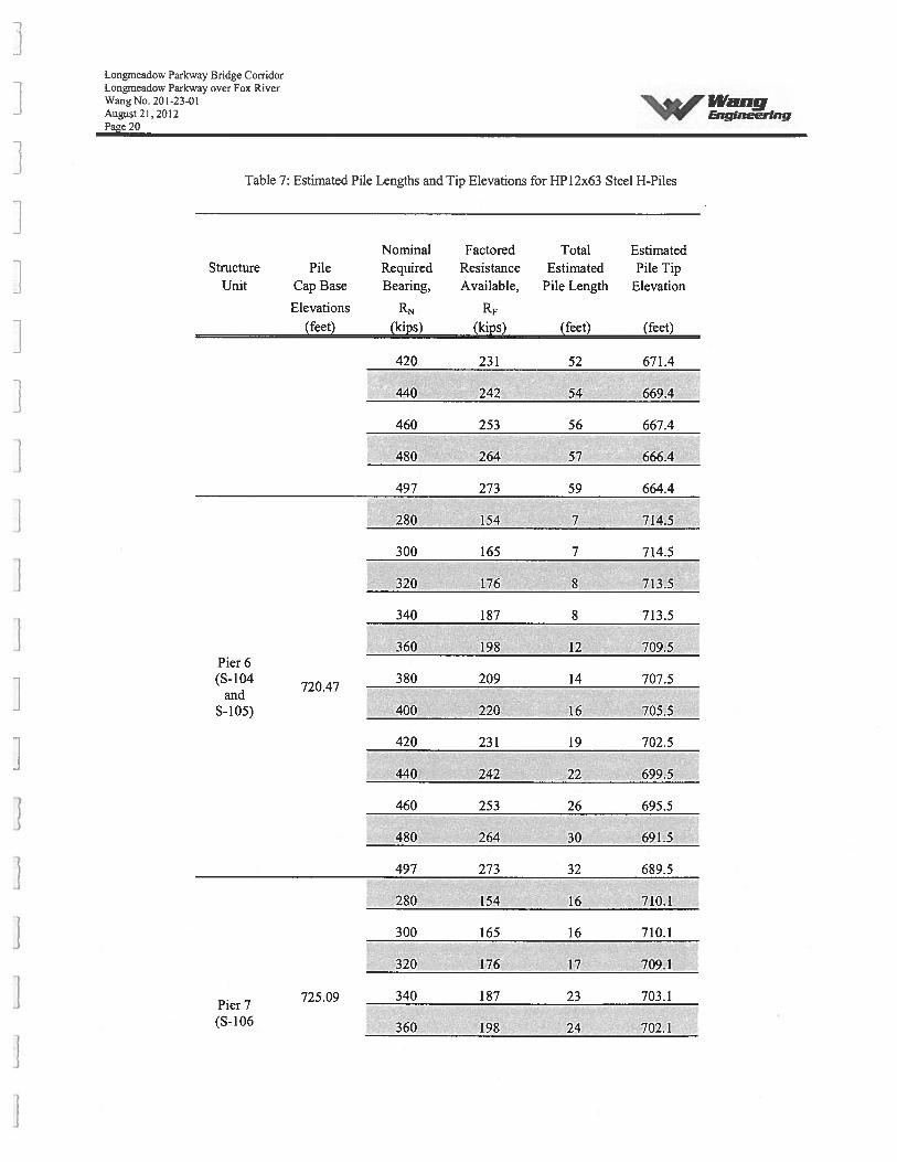
Table 7: Estimated Pile Lengths and Tip Elevations for HP12x63 Steel H-Piles
Structure PileUnit Cap Base
Elevations(feet)
Total EstimatedEstimated Pile Tip
Pile Length Elevation
Pier 6(S-104
and5-105)
Nominal FactoredRequired ResistanceBearing, Available,
RN RF
(p) () (feet) (feet)
420 231 52 671.4
440 242 54 669.4
460 253 56 667.4
480 264 57 666.4
497 273 59 664.4
280 154 7 714.5
300 165 7 714.5
320 176 8 713.5
340 187 8 713.5
360 198 12 709.5
720.47380 209 14 707.5
400 220 16 705.5
420 231 19 702.5
440 242 22 699.5
460 253 26 695.5
480 264 30 691.5
497 273 32 689.5
280 154 16 710.1
300 165 16 710.1
320 176 17 709.1
725.09 340 187 23 703.1
360 198 24 702.1
Pier 7(S-106
Longmeadow Parkway Bridge CorridorLongmeadow Parkway over Fox RiverWang No. 201-23-01August 21, 2012Pace 21
‘A,WangEngineering
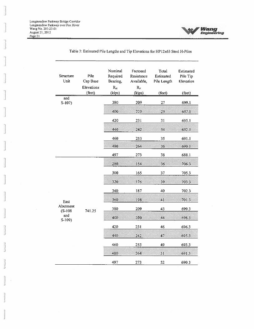
Table 7: Estimated Pile Lengths and Tip Elevations for HP12x63 Steel H-Piles
Structure PileUnit Cap Base
Elevations(feet)
andS-107)
Total EstimatedEstimated Pile Tip
Pile Length Elevation
Nominal FactoredRequired ResistanceBearing, Available,
RN
() () (feet) (feet)
380 209 27 699.1
400 220 29 697.1
420 231 31 695.1
440 242 34 692.1
460 253 35 691.1
480 264 36 690.1
497 273 38 688.1
280 154 36 706.3
300 165 37 705.3
320 176 39 703.3
340 187 40 702.3
360 198 41 701.3
380 209 43 699.3
400 220 44 698.3
420 231 46 696.3
440 242 47 695.3
460 253 49 693.3
480 264 51 691.3
497 273 52 690.3
EastAbutment
(S-b 8and
S-109)
741.25
Longnieadow Parkway Bridge CorridorLongmeadow Parkway over Fox RiverWang No. 201-23-01August 21, 2012Page 22
‘WrWangEnqineerIng
Table 8: Estimated Pile Lengths and Tip Elevations for HP14x73 Steel H-Piles
Nominal Factored Total EstimatedStructure Pile Required Resistance Estimated Pile Tip
Unit Cap Base Bearing, Available, Pile Length Elevation
Elevations RN Rf(feet) (kips) (kips) (feet) (feet)
360
380
400
420
440WestAbutment
460(S-092 762.12and
480S-093)
500
520
540
560
198 40 723.1
209 41 722.1
220 44 719.1
231 46 717.1
242 48 715.1
253 50 713.1
264 52 711.1
275 55 708.1
286 58 705.1
297 60 703.1
308 62 701.1
578 318 64 699.1
360 198 39 706.6
380 209 42 703.6
400 220 44 701.6
420 231 46 699.6
440 242 48 697.6
460 253 50 695.6
480 264 52 693.6
500 275 54 691.6
520 286 55 690.6
540 297 57 688.6
560 308 59 686.6
Pier 1(S-094
andS-095)
744.63
Longmeadow Parkway Bridge Con-idorLongmeadow Parkway over Fox RiverWang No. 201-23-01August 21, 2012Paee 23
‘-4WrWangEngiaeennj
Table 8: Estimated Pile Lengths and Tip Elevations for HP14x73 Steel H-Piles
Nominal Factored Total EstimatedStructure Pile Required Resistance Estimated Pile Tip
Unit Cap Base Bearing, Available, Pile Length Elevation
Elevations RN R
(feet) (kips) (kips) (feet) (feet)
Pier 2(S-096
720.28and
S-097)
578 318 61 684.6
360 198 19 702.3
380 209 20 701.3
400 220 22 699.3
420 231 24 697.3
440 242 27 694.3
460 253 28 693.3
480 264 30 691.3
500 275 32 689.3
520 286 33 688.3
540 297 35 686.3
560 308 37 684.3
578 318 39 682.3
360 198 25 695.4
380 209 26 694.4
400 220 28 692.4
420 231 29 691.4
440 242 31 689.4
460 253 32 688.4 -
480 264 34 686.4
500 275 35 685.4
520 286 37 683.4
540 297 38 682.4
560 681.4
Pier 3(S-098
andS-099)
719.4
308 39
Longmeadow Parkway Bridge CorridorLongmeadow Parkway over Fox RiverWang No. 201-23-01 14”aigAugust 21,2012 &lglneeringPage 24
Table 8: Estimated Pile Lengths and Tip Elevations for HP14x73 Steel H-Piles
Nominal Factored Total EstimatedStructure Pile Required Resistance Estimated Pile Tip
Unit Cap Base Bearing, Available, Pile Length Elevation
Elevations RN RF
(feet) (kips) (kips) (feet) (feet)
578 318 41 679.4
360 198 29 691.5
380 209 30 690.5
400 220 32 688.5
420 231 34 686.5
440 242 36 684.5Pier 4(S-100
719.53460 253 38 682.5
andS-101) 480 264 39 681.5
500 275 41 679.5
520 286 42 678.5
540 297 44 676.5
560 308 45 675.5
578 318 46 674.5
360 198 39 684.4
380 209 41 682.4
400 220 44 679.4
420 231 45 678.4
440 242 47 676.4
460 253 49 674.4
S-103)722.36 480 264 50 673.4
500 275 52 671.4
520 286 54 669.4
540 297 55 668.4
Longmeadow Parkway Bridge CorridorLongmeadow Parkway over Fox RiverWang No. 201-23-01August21. 2012Page 25
WrWimgEngineering
Table 8: Estimated Pile Lengths and Tip Elevations for HP14x73 Steel H-Piles
Nominal Factored Total EstimatedStructure Pile Required Resistance Estimated Pile Tip
Unit Cap Base Bearing, Available, Pile Length Elevation
Elevations RN(feet) (kips) (kips) (feet) (feet)
560 308 57 666.4
578 318 58 665.4
Pier 6(S-104
720.47and
S-i 05)
.____
7 714.5
380 209 8 713.5
400 220 8 713.5
420 231 10 711.5
440 242 H 710.5
460 2___ 709.5
480 264 17 704.5
500 275 702.5
520 286 24 697.5
540 297 25 696.5
560 308 29 692.5
578 3 H 690.5
360 198 16 710.1
380 209 17 709.1
400 220 22 704.1
420 231 24 702.1
440 242 25 701.1
460 253 28 698.1
480 264 30 696.1
500 275 32 694.1
520 286 33 693.1
Pier 7(S-l06
andS-107)
725.09
Longmeadow Parkway Bridge CorridorLongmeadow Parkway over Fox RiverWang No. 201-23-01 IVdiigAugust 21. 2012 &ineeringPage 26
Table 8: Estimated Pile Lengths and Tip Elevations for HPl4x73 Steel H-Piles
Nominal Factored Total EstimatedStructure Pile Required Resistance Estimated Pile Tip
Unit Cap Base Bearing, Available, Pile Length Elevation
Elevations RN RF•
(feet) (kips) (kips) (feet) (feet)
540 297 35 691.1
560 308 36 690.1
578 318 37 689.1
360 198 37 705.3
380 209 38 704.3
400 220 39 703.3
420 231 41 701.3
East 440 242 42 700.3
Abutment741.25 460 253 43 699.3
S-109)480 264 44 698.3
500 275 46 696.3
520 286 47 695.3
540 297 49 693.3
560 308 50 692.3
578 318 52 690.3
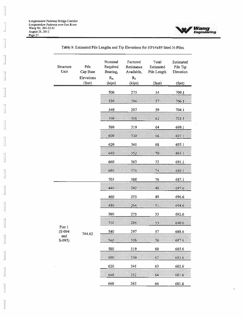
Table 9: Estimated Pile Lengths and Tip Elevations for HPl4x89 Steel H-Piles
Nominal Factored Total EstimatedStructure Pile Required Resistance Estimated Pile Tip
Unit Cap Base Bearing, Available, Pile Length Elevation
Elevations R\ RF(feet) (kips) (kips) (feet) (feet)
West440 242 47 716.1Abutment
(S-092 762.12460 253 49 714.1and
S-093)480 264 51 712.1
Longmeadow Parkway Bridge CorridorLongmeadow Parkway over Fox RiverWang No. 201-23-01August 21, 20 12Page 27
‘%A, WangEnqiaeerfng
Table 9: Estimated Pile Lengths and Tip Elevations for HP14x89 Steel H-Piles
Nominal Factored Total EstimatedStructure Pile Required Resistance Estimated Pile Tip
Unit Cap Base Bearing, Available, Pile Length Elevation
Elevations RN Rf
(feet) (kips) (kips) (feet) (feet)
500 275 54 709.1
520 286 57 706.1
540 297 59 704.1
560 308 62 701.1
580 319 64 699.1
600 330 66 697.1
620 341 68 695.1
640 352 70 693.1
660 363 72 691.1
680 374 74 689.1
Pier 1(S-094
andS-095)
744.63
705 388 76 687.1
440 242 48 697.6
460 253 49 696.6
480 264 51 694.6
500 275 53 692.6
520 286 55 690.6
540 297 57 688.6
560 308 58 687.6
580 319 60 685.6
600 330 62 683.6
620 341 63 682.6
640 352 64 681.6
660 363 64 681.6
Longmeadow Parkway Bridge CorridorLongmeadow Parkway over Fox RiverWangNo.201-23-01August21, 2012 &iglneerfngPage 28
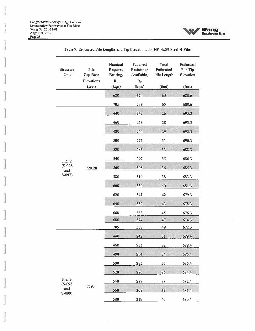
Table 9: Estimated Pile Lengths and Tip Elevations for HP14x89 Steel H-Piles
Nominal Factored Total EstimatedStructure Pile Required Resistance Estimated Pile Tip
Unit Cap Base Bearing, Available, Pile Length Elevation
Elevations RN(feet) (kips) (kips) (feet) (feet)
680 374 65 680.6
705 388 65 680.6
440 242 26 695.3
460 253 28 693.3
480 264 29 692.3
500 275 31 690.3
520 286 33 688.3
540 297 35 686.3Pier 2(S-096
720.28 560 308 36 685.3and
S-097) 580 319 38 683.3
600 330 40 681.3
620 341 42 679.3
640 352 43 678.3
660 363 45 676.3
680 374 47 674.3
705 388 49 672.3
440 242 31 689.4
460 253 32 688.4
480 264 34 686.4
500 275 35 685.4
520 286 36 684.4
Pier 3 540 297 38 682.4(S-098
719.4and 560 308 39 681.4
S-099)
580 319 40 680.4
Lougmeadow Parkway Bridge CorridorLongmeadow Parkway over Fox RiverWang No. 201-23-01 I’VaflgAugust 21,2012Page 29
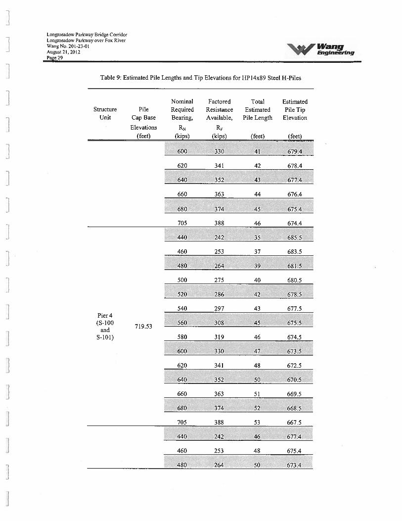
Table 9: Estimated Pile Lengths and Tip Elevations for HP14x89 Steel H-Piles
Nominal Factored Total EstimatedStructure Pile Required Resistance Estimated Pile Tip
Unit Cap Base Bearing, Available, Pile Length Elevation
Elevations RN R(feet) (kips) (kips) (feet) (feet)
600 330 41 679.4
620 341 42 678.4
640 352 43 677.4
660 363 44 676.4
680 374 45 675.4
705 388 46 674.4
440 242 35 685.5
460 253 37 683.5
480 264 39 681.5
500 275 40 680.5
520 286 42 678.5
540 297 43 677.5Pier4(S-100
719.53560 308 45 675.5
andS-b!) 580 319 46 674.5
600 330 47 673.5
620 341 48 672.5
640 352 50 670.5
660 363 51 669.5
- 680 374 52 668.5
705 388 53 667.5
• 440 242 46 677.4
460 253 48 675.4
480 264 50 673.4
Longmeadow Parkway Bridge CorridorLongrneadow Parkway over Fox RiverWang No. 201-23-01August 21. 2012Page 30
“3’,WangEngineering
Table 9: Estimated Pile Lengths and Tip Elevations for HP14x89 Steel H-Piles
Nominal Factored Total EstimatedStructure Pile Required Resistance Estimated Pile Tip
Unit Cap Base Bearing, Available, Pile Length Elevation
Elevations RN Rf(feet) (kips) (kips) (feet)
722.36(feet)
Pier 5 500 275 52 671.4(S-i 02
and 520 286 53 670.4S-I 03)
540 297 55 668.4
560 308 56 667.4
580 319 58 665.4
600 330 59 664.4
620 341 61 662.4
640 352 62 661.4
660 363 63 660.4
680 374 64 659.4
705 388 65 658.4
440 242 11 710.5
460 253 14 707.5
480 264 16 705.5
500 275 19 702.5
520 286 21 700.5Pier 6(S-104
720.47540 297 25 696.5
andS-los) 560 308 28 693.5
580 319 30 691.5
600 330 33 688.5
620 341 35 686.5
640 352 36 685.5
660 363 38 683.5
Longmeadow Parkway Bridge CorridorLongrneadow Parkway over Fox RiverWang No. 201-23-01August 21, 2012Page 31
4AFWangEngineering
Table 9: Estimated Pile Lengths and Tip Elevations for HP14x89 Steel H-Piles
Nominal Factored Total EstimatedStructure Pile Required Resistance Estimated Pile Tip
Unit Cap Base Bearing, Available, Pile Length Elevation
Elevations RN(feet) (kips) (kips) (feet) (feet)
680 374 40 681.5
705 388 42 679.5
Pier 7(S-106
725.09and
S-107)
440 242 25 701.1
460 253 27 699.1
480 264 29 697.1
500 275 31 695.1
520 286 33 693.1
540 297 34 692.1
560 308 36 690.1
580 9 37 689.1
600 330 38 688.1
620 3 39 687.1
640 352 40 686.1
660 363 42 684.1
680 374 43 683.1
705 388 45 681.1
440 242 41 701.3
460 253 43 699.3
480 264 44 698.3
500 275 45 697.3
520 286 47 695.3
540 297 48 694.3
560 308 50 692.3
EastAbutment
(S- 109and
S-i 09)
741.25
L.ongmeadow Parkway Bridge CorridorLongmeadow Parkway over Fox RiverWang No.201-23-01 IVaflgAugust 21,2012 EnqineerinqPage 32
Table 9: Estimated Pile Lengths and Tip Elevations for HP14x89 Steel H-Piles
Nominal Factored Total EstimatedStructure Pile Required Resistance Estimated Pile Tip
Unit Cap Base Bearing, Available, Pile Length Elevation
Elevations RN Rf(feet) (kips) (kips) (feet) (feet)
580 319 51 691.3
600 330 53 689.3
620 341 54 688.3
640 352 56 686.3
660 363 57 685.3
680 374 59 683.3
705 388 62 680.3
The soil immediately below the pile cap should not be considered as carrying any vertical load.The estimated lengths shown in the tables include one foot of embedment into the pile capfooting. The base of all pile footings should be established at a minimum depth of 4 feet belowthe finished grade for frost protection.
The most economical pile sizes should be selected. Precoring through embankment fill isrecommended to avoid downdrag load on the piles and is discussed in the earlier section of thereport. The maximum structural design capacity of the pile and the spacing should be as perIDOT Bridge Manual (IDOT 2009). One test pile should be identified on the plans at eachsubstructure (total of 9 for the bridge structure) which should be installed prior to production pileinstallation. There is no need for a frill scale load test. We recommend that the piles be installedwith pile shoes.
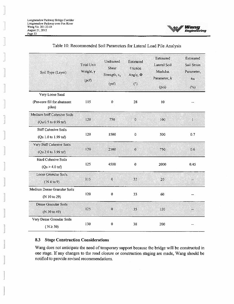
8.2.4 Pile Resistance to Lateral LoadsLateral loads on piles should be analyzed for maximum moments and lateral deflections. Thegeotechnical resistance factor of 1.0 should be used. No allowance should be made for thefrictional resistance of the cap concrete on soil. The required lateral capacity can be obtained byincreasing the pile size and/or number of piles. Battered piles can be considered to resist the lateralloads. The lateral load capacity analysis can be performed using computer program such as COMP624P, L-pile, LATPILE or any other such program. The estimated soil parameters that may beused for the analysis of stresses and deflection under lateral loads are presented in Table 10.Group action should be considered in calculating total lateral load resistance of the substructures.
Longmeadow Parkway Bridge CorridorLongrneadow Parkway over Fox RiverWang No, 201-23-01 IVaflgAugust 21,2012Page 33
Table 10: Recommended Soil Parameters for Lateral Load Pile Analysis
Estimated EstimatedUndrained Estimated
Total Unit Lateral Soil Soil StrainShear Friction
Soil Type (Layer) Weight,’ Modulus Parameter,Strength, c Angle, 0
(pcf)Parameter, k E50
(psf) (°)(pci) (%)
Very Loose Sand
(Pre-core fill for abutment 1 15 0 28 10 --
piles)
Medium Stiff Cohesive Soils120 750 0 100
(Qu 0.5 to 0.99 tsf)
Stiff Cohesive Soils120 1500 0 500 0.7
(Qu 1.0 to 1.99 tsf)
Very Stiff Cohesive Soils120 2500 0 750 ‘ 0.6
(Qu 2.0 to 3.99 tsf)
Hard Cohesive SoilsL25 4500 0 2000 0.45
(Qu> 4.0 tsf)
Loose Granular Soils115 0 32 20 --
( N 4 to 9)
Medium Dense Granular Soils120 0 33 60 --
(N 10 to 29)
Dense Granular Soils125 0 35 120 --
(N 30 to 49)
Very Dense Granular Soils130 0 38 200 --
(N 50)
8.3 Stage Construction Considerations
Wang does not anticipate the need of temporary support because the bridge will be constructed inone stage. If any changes to the road closure or construction staging are made, Wang should benotified to provide revised recommendations.
Longmeadow Parkway Bridge CorridorLongmeadow Parkway over Fox RiverWang No. 201-23-01August 21,2012 EnçineeringPage 34
9.0 CONSTRUCTION CONSIDERATIONS
9.1 Site Preparation
All vegetation, surface topsoil, and debris should be cleared and stripped where approachembankment fills and bridge substructures will be placed. The exposed subgrade should beproofrolled. To aid in locating unstable and unsuitable materials, the proofrolling should beobserved by a qualified engineer. Any unstable or unsuitable materials should be removed andreplaced with compacted structural fill as described in Section 9.3.
9.2 Excavafion and Utilities
Excavations should be performed in accordance with local, State, and federal regulations. Thepotential effect of ground movements upon nearby utilities should be considered duringconstruction.
No utility conflicts were identified that would impact the foundation design. However, theContractor should ensure there are no utility conflicts with the final design and constructionprogram.
9.3 Filling and Backfifling
Embankment fill required to attain the final design subgrade elevations should be in accordancewith Section 205 of the 1DOT Standard Specifications (DOT 2007). All fill and backfill materialsshould be pre-approved by the site engineer. The fill should be free of organic materials anddebris. The backfill behind the abutments should be in accordance with IDOT Bridge Manual(DOT 2009).
Embanlcments should be constructed as early as possible in the project construction period inorder to allow the embankments to adjust or settle under their own weight as much as possibleprior to piles installation for the abutments. The piles installation should be delayed as much aspossible after completion of the embankrnents to their full design heights.
9.4 Earthwork Operations
The required earthwork can be accomplished with conventional construction equipment. Moistureand traffic will cause deterioration of exposed subgrade soils. Precautions should be taken by thecontractor to prevent water erosion of the exposed subgrade. A compacted subgrade will minimizewater runoff erosion. Earth moving operations should be scheduled to not coincide with excessivecold or wet weather (early spring, late fall or winter). Any soil allowed to freeze or soften due tothe standing water should be removed. Wet weather can cause problems with subgrade
Longmeadow Parkway Bridge CorridorLongrneadow Parkway over Fox RiverWang No. 20 1-23-01August 21,2012 EngineeringPage 35
compaction. It is recommended that an experienced geotechnical engineer be retained to inspectthe exposed subgrade, monitor earthwork operations, and provide material inspection servicesduring the construction phase of this project.
9.5 Pile Installation
Piles should be installed in accordance with Section 512 of the IDOT Standard Specifications andSpecial Provisions. The length of the test pile should be at least 10 feet longer than the estimatedlength of the piles. The diameter of the precored hole should be 20” and 24” for the H-pile size of12-inch and 14-inch sections respectively. The holes should be preaugered or precored for pileswhich are to be driven through dense to very dense granular soils containing cobbles andboulders. The boring logs show depths of dense to very dense granular soils and containingcobbles and boulders. The depth to preauger or precored hole should be based on the contractor’smeans and method.
9.6 Cofferdam
As per TSL Plans, pier will be a pile bent supported on three rows of piles and water at the projectsite is expected to be less than 10 feet deep. Therefore cofferdam and seal coat will not benecessary for construction of the river pier. Excavation required can be performed in accordancewith DOT Special Provision “Underwater Structure Excavation Protection”. Cofferdams will berequired if the pile supported footings are 10 feet or more below Estimated Water SurfaceElevation (EWSE). EWSE was not available at the time of this report.
Longrneadow Parkway Bridge CorridorLongmeadow Parkway over Fox RiverWanNo. 201-23-01 WangAugust2l.2012 EngineeringPa2e 36
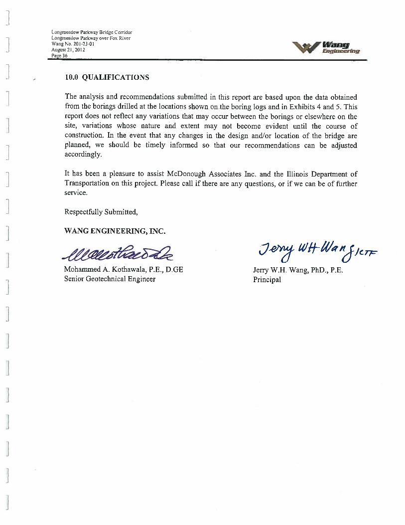
10.0 QUALIFICATIONS
The analysis and recommendations submitted in this report are based upon the data obtainedfrom the borings drilled at the locations shown on the boring logs and in Exhibits 4 and 5. Thisreport does not reflect any variations that may occur between the borings or elsewhere on thesite, variations whose nature and extent may not become evident until the course ofconstruction. In the event that any changes in the design and/or location of the bridge areplanned, we should be timely informed so that our recommendations can be adjustedaccordingly.
It has been a pleasure to assist McDonough Associates Inc. and the Illinois Department ofTransportation on this project. Please call if there are any questions, or if we can be of furtherservice.
Respectfully Submitted,
WANG ENGINEERING, INC.
7eiy Wif
Mohammed A. Kothawala, P.E., D.GE Jerry W.H. Wang, PhD., P.E.Senior Geotechnical Engineer Principal
Longmeadow Parkway Bridge CorridorLongrneadow Parkway over Fox RiverWang No. 201-23-01 IVaflgMarch 31.2011 Engineering
REFERENCES
AASHTO, 2007, LRFD Bridge Design Specifications: Washington, D.C., American Association ofState Highway and Transportation Officials.
Bardet, J.-P., 1997, Experimental Soil Mechanics, Prentice-Hall, Inc.
Bowles, J. E., 1968, Foundalion Analysis and Design, McGraw-Hill Book Company.
IDOT 1999. Geotechnical Manual. Illinois Department of Transportation.
IDOT 2007. Standard Specifications for Road and Bridge Construction. Illinois Department ofTransportation, 1172 pp.
IDOT, 2009, Bridge Manual, Illinois Department of Transportation.
ISGS April, 2001. Guidebook for Field Trips for the Thirty-Fifth Annual meeting of the North-Central Section of the Geological Society of America. Illinois State Geological Survey.
ISGS May 2000. Director,’ of Coal Mines in Illinois, La Salle County. ISGS.
Geotechnica! Con.crniciion . El7iiromnenlalQua//ti Engineering Services Since 1982
Ii
(l
——
LJ
LJ
LL
LL
_J
L_J
L_J
L—
:-
-•1t3
!z:
oje
ct
Sta
rtR
anda
llR
oj
IST
A.2
001+
0O—
—r
.•::\
?-i
--
-
_____
Sle
epy
Hol
low
4•)
-20
98+
00
__
__
-‘:
?
__
_
j4,•
—.
‘it
r3..
4I4l
l
I.“..-
,-
.
.1
1.
—
i?’—’
ç1>
i.
-.;-i
Fox
Riv
er‘,
US
Rou
te25
-jfr
..:
[22
1o
+3
5Y
-22
70+
75
M4
.
1T1-
J,-
-‘r-
“:.‘
-‘-
Pro
ject
End
-].;l
I—
—-
)ll
lin
oR
oute
62
¶.
/i
“‘
PRO
JEC
TLO
CA
TIO
NM
AP:
LON
GM
EAD
OW
PARK
WA
YO
VER
FOX
RIV
ER.
-.
IDO
TN
O.P
-91-
393-
94.
KA
NE
CO
UN
TY, I
LLIN
OIS
DR
AW
NB
YN
DB
SC
AL
EG
1utP
HIC
EXH
IBIT
1
.
_____
/‘%
‘iV
an
g-
.-4’
-v!v
rE
nq
iner,
nq
“—
-\
.;‘.&
4çtc,-’
-.
..,
ER
SV
dL
rFO
RM
cDO
NO
UG
HA
SSO
CIA
TES
INC
201-2
3-0
1
IM
iLE
,fJ
•‘•s
-
S.,
-
z
-\.‘
(
,--—
‘‘
_//
I
-7
f.—
,,,,
O,
,.//
Y_..
‘f_
7’7/
(L
-1
‘4
r..
‘L
‘)
N
I:1
i)
.L1 ‘
\
ç•)
€-
,,,/
)
I/i
t /A
1/
.
-/
‘I
/1’
//1
)
0
I,
-I
0.5
II
I1.
0M
ile
/I ‘,
“•H
KA
NE
CO
UN
TY
SITE
LO
CA
TIO
NM
AP:
Lo
ngm
ead
ow
Par
kway
ov
erFo
xR
iver
,ID
OT
NO
.P
-91-
393-
94,
KA
NE
CO
UN
TY
GRA
PHIC
AL.
EXH
IBIT
2I D
RHW
NBY
.ND
B.
CHEC
KED
BYM
.A.K
.
114
SN
.M
ain
SBLB
eBi’
l’an
gL
omba
rd,
IL60
148
Engin
eeri
ng
ww
w.w
ange
ng.c
om
FOR
MC
DO
NO
UG
HA
SSO
CIA
TES,
INC.
1201
-23-
01
950
900
850
800
750
700
650
ITE AND REGIONAL GEOLOGY: LONGMEADOW PARKWAY OVER FOX
RIVER. DOT NO. P-91-393-94. KANE COUNTY, ILLINOIS
‘DRAWN BY: N.D600EXHIBIT 3 ICHECKEDBY.MA.K
ALE GRAPHIC
jIIØI_Iaflg1145 N. Main StreetLombard, IL 60148
Engineering www.wangeng.com
N
REGIONAL GEOLOGY
20 ml
Wedron Group
Wadsworth Formation
IiBAgSt
Lemont Formation
Tiskilwa Formation
Modified after Hansel and Johnson (1996)
LITHOGRAPHIC UNITSQuarternary Deposits
Mad. Ia sd
Hudson Episode (postglacial)r-i Graynlak. Peat
gr Peat and muck, including interbedded sand, silty clay, and madDecomposed wetand vegetation and sediment.Cahokia FerreatissSand and gravel. well-sorted send, and lenses ci peat adjacent to sysams.grading laterally to organic-rich. fossilfemiis silt and clayFloodplain sediment.
Hudson and Wisconsin Episoder1 Equality Foreratlos, Meson Group
e, ep Silt, clay, and fine sand; layered lv massive, tossilifenous in many places.Lake deposits in ketden and some valleys flibutary lv the ton river.
Wisconsin Episoder..r.....1 Henry Foenatloo. Mason Group
h ‘Sand and grauel, or sand; vvntains lenses 015 It and clay, or diamiofionOulwanh Deposits along valleys and beyond former glacier margins.Henry Formation (fin. fades), Masoe Grsup
h(f) Fine to medium sand; uniform to layered, wiry lenses 01 iossilliervcn sill andcam diomivtivn al bane Lake sediment slope deposits.
D nody loem bo loam; dolomite rich yrvluden lenses and layers of
Till and debris flow deposits.Yorkoille Member, Lemont Formation, W.dros Group
I Diamicton’ silty vlay. silty clay loam, and clay with think lenses of sand ond gravelY Till and debris flow deposits where nurlivial; proglavial
lake sediment and YB where burned by the Haegar Member
Asndyloanrtolcamwitlrrbundontvobbien,brckudescorhfluous layers of
Till and debris tow deposits.
Henry Formation, Mason GroupAss’gned to the Beverly Tongue (hbj where buried by the toe yanger Member,
T1nkIIWa Formation
t Diamicton; loam to vlay loam with lenses of sand and gravel.Till and debys tow deposits.
Henry Formation, Manes GroupAssigned to the Ashmore Tvngue where burned by the Tiskilwa Formation.
Illinois EpisodeGlanfend FormatIon
9 D:amivlon; loam to sandy loam. bocldery with abundant tenses of coarse sand and gravel.Till and debris Ion deposits. outwash and lacustnlre sediments.
Paleozoic BedrockKaskatre. aed .1011.1 Formation. (Silunianf; M.qaak.ta GroupDolomite with vhen tenses; gray to y.Icwnh becwn. fvssihfervuo, usggy; ama shalydolomite and brown shale
- ______________________________________
FOR McDONOUGH ASSOCIATES, INC. 201-23-01
LL
LI’I
I’
II
LJ
LJJ
L—
——
—
‘
(
I
‘
røIf
f\
\,
II
BO
RIN
GLO
CA
TIO
NM
AP
:LO
NG
MEA
DO
WPA
RKW
AY
OV
ERFO
XRI
VER
IDO
TN
O.
P91
-393
-94.
KA
NE
CO
UN
TY,I
LLIN
OIS
SCA
LEG
RA
PHIC
EXH
IBIT
4IB
RD
0W
O20
030
0
let
5015
025
035
0F
eet
v!v
rE
ngin
eeri
ng
ww
w.w
angen
g.C
om
IF0R
MC
D0N
0UG
HA
SSO
CIA
TES,
INC.
201-2
3-0
1
Ebnchi Uark Cats. “D S.E. C0R COlIC. SLAB.Tie fIlL of ILL. 31 and UJi(er Rd. go FL 0.9 MI S to Mark.Elf. 806.34
Existing Structure: lIanc
Bock of W. Abut—1Sta 220561.78Elev. 774.29
* *5-089 5-091
: \K’
5-088 4_4* 5Q9Q*
r Proposed Drainage
I Scuppers(TypJ. See Cross
/ Section
Brg. W. Abuf Pier 1
Sto. 22051-65.40 Sta. 2206”85.40
Elev. 774.28 Elev. 773.36
*Ico
‘lIC\J
(;c11Z fr-ç
csJI: O,j’
1j
PVI STA =22Q384.i4PVI ELEV= 775.62A.D.=-3.25K=123.08
(Sondbloom Road)Functional Class: Local
ADT: 2.814 (2004)ADTT: 2.814 (2004)
DIiV: 422 (2004)Design Speed: 40 m.p.h.
Posted Speed: 35 mp.h.Two- Way Traffic
D!recfionol Distribution: 57143
Hatch Area IndicatesApproximate Limits ofSail Reinforcement
115
1307’- 3” Back to Bock of Abutments ILanameadow Parkway Sta. 2218 05.51
123’-7 - - 200’-O” Span 2 300’-O” Span 3 200’-O” Span 4 120’-O” Span 5 120’-O” Span 6 120’-O” Span 7 - 123’-7 -
120’- 0’ Span 1 j5°0’O
_______________
sk
0
Longmeadow \
\
_________________
ParkwaY&PGL”\\
-w S-QN 1
I \- 220IQQ .,, 221Q1.QQ\ ‘rj22±200
S-094.\ -°N , . /.s-o98
=
HIGHWAY CL A SSIFICA TION
Sandblaam Road Sta. 905 99.89
\ S-101
Brg. Pier 6Sb. 2216 25.40Elev. 766.31
\{
120’-O” Sprn 8
Brg. Pier 7—Sta. 2217”45.40Elev. 765.41
S-1Q
(Longmeadaw Parkway)Functional Class: Minor Arterial
ADT: 30.000 (2040)ADTT: 1.200 (2020)DM1: 2.400 (2040)
Design Speed: 50 m.p.h.Posted Speed: 45 m.p.h.
Two- Way TrafficDirectional Distribution: 50/50
LOADING HL-93Allow 50#/sq. ft. for future wearing surface.
DESIGN SPECIFICATIONS
\ 10
Kink PointStation 2218 12.35
— =00 13’ 45.85”
Brg. E. AbutSf0 2218*65.40Elev. 764.53
Brg. Pier 2Sta. 2208 ‘-85.40Elev. 771.86
00dcm
‘8-
c\I
Bridge
“—Pier4Sta. 2213’-85.40Elev. 768.11
0a)a)-J
04
S-117
904/V/ZZ/Z/ZAZZZ///J’/A h.
Brg. PierSta. 2215’-05.40Elev. 767.21
_/Brg. Pier 3Sta. 2211’-85.40Elev. 769.61
oo *Imo o’cI-LC) °‘1im•0 CsjO’L()L4I CsjI”=
04k. (niLi
PLAN
—‘=c7 PVI STA=2222’-QOPVI ELEV= 762.00
MSEI LOW PT STA 2219*41.30
___________
LOW PT ELEV. 764.28 Design ScourA.D. = -5.75 Elevation (ft.)K=121.74
/ S-113222200
2010 AASHTQ LRFD Bridge Design SpecificationsIncludina 2010 Interims
DESIGN’ STRESSES
-
LEGEND0 Soil Boring Location
C
II
Ii’
PROFILE GRADE
FIELD UNITSf’c 3.500 psify = 60.000 psi (Reinforcement)fy 50.000 psi (11270 Grade 50)PRECAST PRESTRESSED UNITS
f’c 6.000 psifpu = 270.000 psi (low lax, strandsl
SEISMIC DATASeismic Performance Zone !SPZ)=1
Design Spectral Acceleration of 1.0 sec. !SDJ)=B.2Design Spectral Acceleration at 0.2 sec. ISDS.)=14.4
Soil Site rnass = B
(Along Langmeadow Parkway)
WATERWAY INFORMATION
9(“I
0a)a)
DESIGN SCOUR ELEVATION TABLE
Elev. 764.52
Back of E. Abut S-114 S416
Sta 2218’-69.03
Bridge Approach Slab (Typ.)
GENERAL PLAN & ELEVATIONLONGMEADOW PARKWAY OVER FOX RIVER
SEC 94- 00215- 01-ESKANE COUNTY
STATION 221Ot 35.40SN. 045-3024
W. Abut. Pier 1 Pier 2 Pier 3 Pier 4 Pier 5 Pier 6 Pier 7 E. Abut.762.12 751.63 719.87 718.49 718.91 721.74 719.85 724.47 741.25
Drainage Area * 1364 sq. ml. Law Grade Elev. nb 0 nb
Fl d Freq. 0 Opening Sq. Ft. Ma!. Heod - Ft. l-Ieoo.voter El.00
Yr. C.F.S. Exist. Prop. H.W.E. Exist. Prop. Exist. Prop.10 577, - 2853 727.67 0.00 0.00 .00 727.67
Design 50 8345 - 3990 729.21 0.00 0.00 7.00 729.21Base 100 10095 - 4688 730.09 0.00 0.00 .0O 730.09Overtopping - - - - - - I - -
Max. Ca/c. 500 12525 5643 737.17 0.00 0.01 0.00 731.18
HIGHWAY CL A SSIFICA TION
LSER NAPE DESIGNED - REVISED- I SECTION COUNTY TOTAl. SHEET
sEL’ CHECKED - REVISED- STATE OF ILUNOIS I . 9-1-00215-01 ES KANE
P151 SCAE” DRAWN - REVISED- DEPARTMENT OF TRANSPORTATION L CONTRACT NO.
PLOT OAT! CHECKED - REVISED- I SHEET ). I OF 3 SHEETS I1IL1PCisIT!o. AID PRO.ECT
LOCATION SKETCH
BORING LOCATION PLAN: LONGMEADOW PARKWAY OVER FOX RIVER,IDOT NO. P-91 -393-94, KANE COUNTY, ILLINOIS
‘DRAWN B1 N.D.BI EXHIBIT 5
14’ang 1145 N. Main StreetLombard, IL 60148
Engineering www.wangeng.com
FOR McDONOUGH ASSOCIATES, INC. I 201 -23-01
N
775
765
755
745
735
725
715
705
695
685
675
665
655
645
635
2ts Q:1
. . I, • • • . S
O92
F4 88as
19-h
.NW... .o B
1340
• .15 .520.a.
3252 1.406 12 5-094
..15 220.8 . (2 2206+85.2513 2.257 13 N 13 40
10.3.28.6..
18 3036 73LOOP 12 S.108
• 32 22t8+6t88n72 1278 72
12 2218.940
59 1648 1214
lOOP7 0.570 14 S-106 10 1.25P
5g ¶4 22171144:06 •“••j•_;•j•70:820 14 S-096 15+05.07 S104
15 lOOP . 91.0 13 2208+76.4 2211+85.27 2213+86.07 lO 2216+27.49
13 SlOP j—j-io sloe
.o — 5.534.. 20.04.521 .j.’.9 375 B 17.1.&4B4]j16 1811’ F,.<4522 2.628 14
1.0 8II 1.230 28
640 I ii 8 5 40‘
54.11’ p .‘o 15.140 i ti ‘ 30 MJ40...[fl2II 0.826
,,.14 II 1,070 13 .100i .n,(2 4011’ 2 9 52 OP 1, 0 6011’ L..(8 25 SlOP II
/4•O17.2207. . 2 .f) .P.... 51 5171’... 8 .4I& I
17 1.238 15 21 23240 .061/ 13 lOP 4’.. 10
3511’ 16”: II 11 2140 [.. 28 36
¶468.40 12 2040 11’” :i 16•
27.40.....; 91 2540... &. 3020 1.56B 14 25 3.858 11
18 22 P .1 18l1’ 0 5040 9 3240 l4 10 3.00 P 15
i.soo. ., 122340 •• :: 2214’... i. 0 OP... ..}tI
19 1.566 15 24 4,IIB/
1321 1.800 22 2440 •• 23
611’ 18 16 2.86 B “[ 22 19 2.798 I2T 14 25 2.56P 13
171:64.022.3270 96801257 04 ...
•1•.•I 13.140 ..; 22 14.3.23.6 .J, 29
22 1.89 B 14 21 1.75 P 2315 1.398 / 15 s is
0.75 P 20 20 4.078 r ri 13 21 1.10 P 15
1.
20.40 22
;, :.. 14
.
34:5735¶ ., .., .22.3.300. •• 94 V1,}
23 2.208 14 22 2.620 1415 1.726 11 10 1.726 14
19 1.25 P /, 5 18 1.978 IJL/l 29 2.757 13
646 17. 1.078. (I,,.’. os [ .
22 1.008 / 13 30 1.97 B 1414 1.31 B .‘ 14 20 1.800 14 •—J 15 2.308 /f, 13 24 3.288 [jJ 14 42 P 19
352163•0.22.40.... j.. 06
,
24 2.058 1522 2058 14 18 2.71 B 4 J 2.00B 13 28 3.538 13
:10.2.308. .J. 53.
2.3014
33 2.828LL2’3PL.S 25 2.468 13 27 3.698 12
67 2.21 B 1435 2.876 12 35 1’ • 13
..-.•
5137 2.757 13
#65
865
#65
#NA
775
765
755
745
735
725
715
705
695
685
675
665
655
645
635
0 100 200 300 400 500 600 700 800 900
q
zUi
0.8,
0I,•1
0(N
I..
881
Site Map Scale 1 inch equals 475 feet
Explanation:
S-092
________
2108+00.01 Borehole Number
Borehole LithologyN_N.nue (66412 In)130—12 568.1981. (91)140.4.l4Oone Co96* (9)
Water Level Readingat time of drilling.Water Level Reading24-hr after drilling or atend of drilling
0 130
Horizontal Scale (feet)
Vertical Exaggeration: 4.5x
DISTANCE ALONG PROFILE (feet)
Lithology Graphics
1,000 1,100 1,200 1,300
IDH Clay
IDH Sand, Sandy Ioam lDHSaridy Clay, Sandy ClayWeIS bedrock
[[j]]]] ION Silty Clay, Silty Clay Loam Ddomite or Ddcniitic Limestone . IDH Loam
Gravelly sand, sandy gravel IDH Clay Loam
[{]] IDH Silt, Silty Loam
Wang Engineering, Inc.1145 N Fv’ein StreetLombard, IL 60148
Subsurface Soil data Profile
200 300 400
755
735
725
715
705
695
685
665
655
645
Site Map Scale 1 inch equals 475 feet
S-093
_________
2108+00.01 Borehole Number
_______________
Station
Q*12Borehole Lithology
tQ-$r (hf)
Water Level Readingat time of drilling.
Water Level Reading24-hr after drilling or atend of drilling
0 130
Horizontal Scale (feet)
Vertical Exaggeration: 5x
Wang Engineering, Inc.1145 N Main StreetLombard, IL 60148
Subsurface Soil Data Profile
Longmead Parkway over Fox RiverKane County, Illinois
765
755
745
735
725
715z
705
695
685
675
665
655
645
N
I
424c:1 \c8Oc5l;
765
s932205÷65.65
NO 68.4664’ . 26
91 1.566 72
.14456.6 89
10 i.390 132206+85.66
.15490.8 . 41 NQ,16 .560 42 12 225P
S-109• 49 .1,30.8 ., . 33 till 246
2218+65.1?4 4648 12 29 2.978 13
N 72, 4,07.16.1.72.0 71••4.20
16 1.978 43 7 3.70P 17
• 1207 !1.M’
9 1.318 14 S—103 S—107 tO7S 17
.16.1.208 1.20 S.097 S-099 s-a 2÷45.58
7 2.668 14 2208+69.79 2211+85.55 2213+85.62 2216÷25.34 1 4.S6 13 6 1.078 20
.168 .43
25 i6.8 120828 l2LC81Loon#l 9 L. 1466 20 24536 596 5 23.66 42 3166 0 :: 5078
3616 9 2916 : 2466 ‘..71 10 4756’ 64’ 6 .19 ‘0.:.22 1568
“43 11 1158 13
—. a—1 6276’ 12 5066 10 0.16’ -_ IS 03466 0 2366 i3
/II 2316’ 10 3416’ II 3966
0. 3556’ 69536 & 8 3256’ 9
25 1.86.8 5 2058 1320 2066 66 66
30 2.218 13 966 .164 15 26436 46 6’ 56•.
10 4066 105Q’’ 6’ .. 19 25 1.628 14
23.0.078 “ 31390 15242.200 1’3 4176’ 3’f) 14 466’ ‘ 34 3156 10 3 66 o
8536 - 0
23 3.208 / 13 12 2.258 32136 :i. 24 27 136 18 26 2.06 P ‘ 1320 2309 4 9 3.038 14
.49.2.06.0 .. . 15 2628 34.1.668.1.1 25 .p 20 zooe .:20 20581* 12. /
17 1.398 15 15 3.469 “ 13 19136 Vt:, 27 “. 15 3.719 13t7..2.21 4 ,. 03.2.626 .10 .‘‘?.4
242.748 413 1.400 14 13 2.388 14 28 66 ‘ 15 3.640 13
.20.1.64.8.44 ll.197 22.3.260. ,hl973,, 09
— 18 2.550 / 1* 11 2.468 14 26 2.210 4 14 11 2.540 “ 1320 2.62B 14
ti2.? A ‘ / 12.1.640. .14202.718 13
18 1.998 / 14 10 2.798 14 25 3.368 14 49 3.208 4 ‘ 31ll.9.7.8 d 4 20..l970..7l3 ....f..2..f.4. !‘
36 1_OP 1722 1.908 13 21 3.2. 8 4 13 29 3.778 4 13 21 3.948 / 3
118’ ‘S .4’ .4 36.2.248. 1540 1.757 16
23 3.548 / 13 — 13 27 3.258 13‘
.‘-:•,202.050. . 92
20 1.728 / 14 26 2.71 6 • 12 32 3.038 4 1318.3,20 34.2.820. 15
41 1.150 / 13 25 3.538 “ 12
18 25. . 12
-
— 502’ 1.018 ‘ 14 5081 —8146 0..,..
4446... •. 4
8446 —‘-a
745
ExDlanation:
0 100
00z
675
DISTANCE ALONG PROFILE (feet)
Lithology Graphics
500 600 700 800 900 1,000 1,100 1,200 1,300
IDH Silt, Silty Loani
Gravelly sand, sandy gravel IDH Clay Loam
[[j]]]] IDI-I Silty Clay, Silty Clay Loam IDH Sand. Sandy Loam
Weathered bedrcdc
IDH Loam
[E Boulders and cd±Ies Limestone
IDH SartCy ciay. Sandy ClayDdornite c Delomitic LimestoneLoam
SIM’E 39JOB NUMBER I PLATE NUMBER
201-23-01 EXHIBIT 6B

‘3VWangEnqineering
APPENDIX A
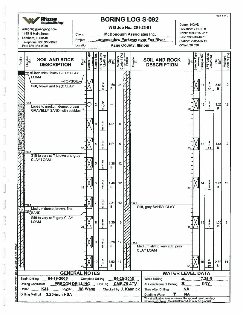
SOIL AND ROCKDESCRIPTION
GENERAL NOTESBegin Drilling 04-19-2005 - Complete Drilling 04-20-200 -
Drilling Contractor .....PREqQN.pR!juNc.... - Dril’ Rig ...c.ME75.ATVDriller K&L Logger W.Wang Checked by J.Kasn!ckDrilling Method 3.25-inch .HSA
SOILAND ROCKDESCRIPTION
WATER LEVEL DATAWhile Drilling V Z5.ftAt Completion of Drilling T DYTimeAfterDrilling NADepth to Water NA
stratification lines represent the anDroximate
Page 1 of 2
Wang BORING LOG S-092Datum: NGVD
wangengwangengcom WEI Job No.: 201-23-01 Elevation: 771.32 ft
1145 N Main Street Client McpgIiqciatçsjnc North: 1993515.22 ft
Project mciow kway.qver.F Rive Station 2205+66.13
Fax: 630 953-9938 Location ?flecUfltY,.!!!iflOiS Offset: 3003R
Cl)
DO. U
GRAVELLY SAND, with cobbles
]

Page 2 of 2
% Wang BORING LOG S-092V Engineering
Datum NGVDwangengwangeng.com WEI Job No.: 201-23-01 Elevation: 771.32 ft
1145 N Main Street Client McDonough Associates Inc. North: 1993515.22 ft
Lombard IL 60148 East: 998239.46 ft
Telephone: 630 953-9928Project n.meadowPa1cwayqverFcx..Rivcr.... Station: 2205+66.13
Fax: 630 953-9938 Location c?necouIy,i!Hnpis Offset: 30.03R
. - 5) .>- ;. -2-
SOILANDROCK SOILANDROCKDESCRIPTION & DESCRIPTION D 2
c 00) 0 0(1) C)
17 0.82 14 22 2.30 1455 g B 80 23 B
F
I
18 1.23 15 23 2.38 1460 io B 85 14 B
F
F
19 1.56 14 24 1.80 1365 12 B 681.3 90 12 B
Boring terminated at 90.00 ft
- 20 1.56 15 -7Q io B 95
21 io 1.89 14B ioo
GENERAL NOTES WATER LEVEL DATABegin Drilling 04-19-2005 - Complete Drilling 04-20-2 While Drilling .ftDrilling Contractor PRECONDRIL.LING Drill Rig ...cM.E45ATV At Completion of Drilling Y DRYDriller K&L Logger W. Wang Checked by J. Knjck Time After Drilling NADrilling Method .2.54n.c.h NSA Depth to Water NA
The stratification lines represent the approximate boundarybetween soil types: the actual transition may be gradual.
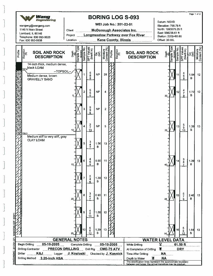
SOILAND ROCKDESCRIPTION
SOILAND ROCKDESCRIPTION
14-inch thick, medium dense,6black LOAM
Medium dense, brownGRAVELLY SAND
--TOPSOIL--
Medium stiff to very stiff, grayCLAY LOAM
While Drilling-
61.50 ftAt Completion of Drilling DRYTime After Drilling NADeoth to Water
Page 1 of 2
%Wang BORING LOG S-093vv Engrneerrng
Datum [email protected] WEI Job No.: 201-23-01 Elevation: 768.78 ft1145 N Main Street Client McPpnPu9hAPciates.!nc North: 1993575.25 ft
Telephone: 630 953-9928Project OW?? way.pverFo Re
- Station: 22O5+655Fax: 630 953-9938 Location Kane C unty,.HImo’s Offset: 30.00L
IBegin Drilling :1.0-2 Complete Drilling 1.0200Drilling Contractor RECON. DR!LL.!.NG Drill Rig •..ç.ME-75.ATVDriller Logger ...J..Kos!osk Checked by asnickDrilling Method .3.2.5-inch ,H$A
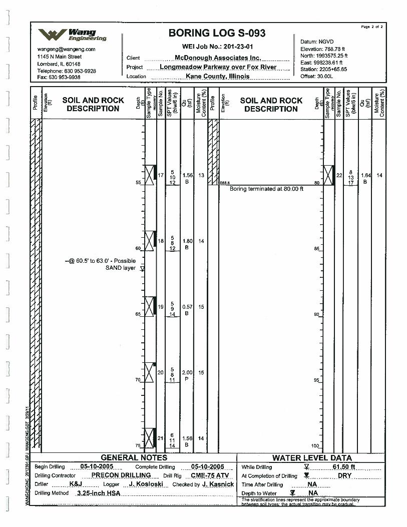
Page 2 of 2¶e4Wang BORING LOG S-093
VV’ EngineeringDatum NGVD
wangeng©wangeng.com WEI Job No.: 201 -23-01 Elevation: 768.78 ft
1145 N Main Street Client McDonough Associates Inc. North: 1993575.25 ft
L b d IL 60148 East: 998238.61 ft
Tephone: 630 953-9928Project me ow yover Fox Rive Station: 2205+65.65
Fax: 630 953-9938 Location Kane County, !!Iinois Offset: 30.OOL
a.
a-
.
- SOILANDROCK SOILANDROCKDESCRIPTION (2 DESCRIPTION (2
0)0) C) Coo) 0
Rfl555 5
Boring terminated at 80.00 ft
2281317
141.64B
I --@ 60.5 to 63.0 - PossibleSAND layer
55
60
65
70
75
17
18
19
20
21
51012
5812
5914
58
11
61114
1.56B
1.80B
0.57B
2.00P
1.56B
13
14
15
15
14
85
90
95
100
ja
002LL02
20
0z0zLU0z
GENERAL NOTES WATER LEVEL DATABegin Drilling -10-2 Complete Drilling 05-10-2005 While Drilling j.QftDrilling Contractor PRECON DRILLING Drill Rig -
- .C.M.-75 ATV - At Completion of Drilling Y DRYDriller K& Logger Kos!osk Checked by J.Kasnick Time After Drilling NADrilling Method 3,Z5-i.n.c.h.HSA Depth to Water N.A
The stratification lines represent the approximate boundary
between
soil types the actual transition may be gradual.
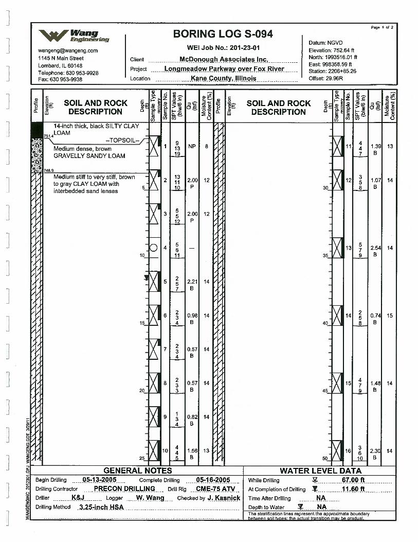
SOIL AND ROCKDESCRIPTION
SOILAND ROCKDESCRIPTION
thick, black SILTY CLAY
--TOPSOIL--
Medium dense, brownGRAVELLY SANDY LOAM
sand lenses
GENERAL NBegin Drilling 05 Complete Drilling 05-Ib-2LJU
Drflling Contractor PRECON DRILLING Drill Rig CME-75ATVDriller K&J Logger W..Waflg Checked by J.KasnickDrilling Method ..3..2.5-in.ch.HSA
R LEVEL DATAWhile Drilling - 67.0Q.ftAt Completion of Drilling Y .60ftTimeAfterDrilling NA
Page 1 of 2
%Wang BORING LOG S-094V’V Engineering
Datum- NGVD
wangengwangengcom WEI Job No.: 201-23-01 Elevation: 752.64 ft
1145 N Main Street Client McDonough Associates Inc North: 1993516.01 ft
T&ephone:30 953-9928Project fl dOWPkWayOVerFO Station: 2206+8S26
Fax: 630 953-9938 Location Kane County, Illinois Offset: 29.96R
]
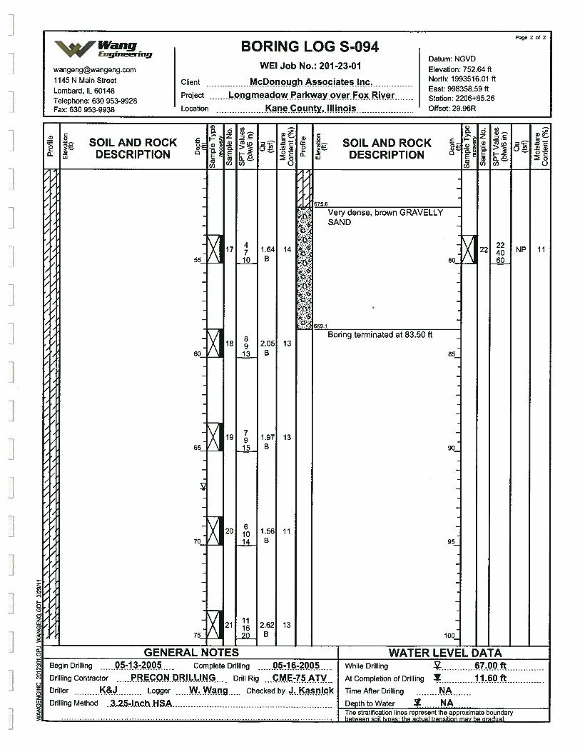
Page 2 of 2r%Wang BORING LOGS-094
vv’ Eng,ne.rrngDatum: NGVD
wangengwangeng.com WEI Job No: 201 -23-01 Elevation: 752.64 ft1145 N Main Street Client McDonough Associates Inc North: 1993516.01 ft
L b d IL 60148 East: 998358.59ft
T&ephone: 630 953-9928Project flme?dowPaIkwayoverFo RiVer
- Station: 2206+85.26
Fax: 630 953-9938 Location Kçylllino)s Offset: 29.96R
a)- Co - )
. Co0 .
.
i. SOILANDROCK SOILANDROCK
DESCRIPTION U & DESCRIPTION U
c COO) ( COO) C)
675.6
Very dense, brown GRAVELLYSAND
:£..:•
8Q•:p.
te
t:t. 669.1
22 NP60
11
Boring terminated at 83.50 ft
55
60
65
70
75
17 1.6410 B
18 2.0513 B
19 1.9715 B
20 1.5614 B
21 2.6220 B
14
13
13
11
13
85
90
95
100
0(p
I (7z
(9zLU(I,z
GENERAL NOTES WATER LEVEL DATABegin Drilling Complete Drilling -16-2005 While DrHhing V 67.00 ftDrilling Contractor PRECON DRILLING DrillRig CME-75ATV AtcompletionofDrilling Y .60ftDriller K& Logger W.wang Checked by Time After Drilling NADrilling Method ..3..25-i.n.c,h..HSA Depth to Water N.A
The stratification lines represent the approximate boundary
between
soil types: the pr.tusl transition may be aradual
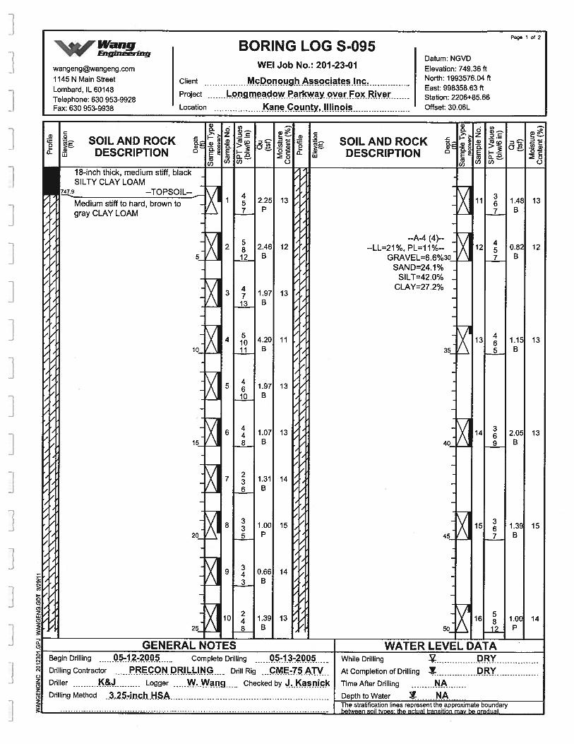
Page 1 of 2
%Wang BORING LOG S-095vv EnganrrngDatum NGVD
wangengwangeng.com WEI Job No.: 201-23-01 Elevation: 749.36 ft1145 N Main Street Client McDonough Associates Inc. North: 1993576.04 ft
Lombard IL 60148 East: 998358.63 ft
Telephone: 630 953-9928Project ,gmeadow rkway Fox River Station: 2206+85.66
Fax: 630 953-9938 Location Kane County, Illinois Offset: 30.06L
ci)0=0
a-SOILAND ROCK
DESCRIPTION(0
.0
747.9
C-)
ci)0=0a-
--TOPSOIL--
Medium stiff to hard, brown togray CLAY LOAM
2.25P
13
2.46B
125
13
1.97B
12
10
4.20B
1.97B
13
/
SOILAND ROCKDESCRIPTION
--A-4 (4)----LL=21%, PL=11%--
GRAVEL=6.6%30_SAND=24.1% -
SILT=42.O%CLAY=27.2%
35
40
45
50
13
11
13
13
14
15
15
1.07B
1.31B
13
201.00P
0.66B
14
15
25
1.39B
13
GENERAL NOTESBegin Drilling 5-1.2-2005 Complete Drilling ...Q1.3.-200Drilling Contractor RECONDRIL.ING Drill Rig ...c.ME-75.ATV.Driller K& Logger W...Wng Checked by 3.Ka1Drilling Method
. .3,25-i.n.chHSA
14
WATER LEVEL DATAWhile Drilling
At Completion of Drilling
DRYDRY
Time After Drilling NADepth to Water I N.AThe stratification lines represent the approximate boundaryhotwoon onil tunoc tho ,riiioi tronqitinn mow ho nrorlrroi
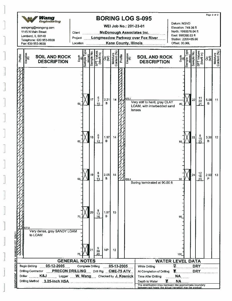
Page 2 of 2
‘%Wang BORING LOG S-095‘v’v gig
Datum NGVDwangengwangeng.com WEI Job No.: 2012301 Elevation: 749.36 ft1145 N Main Street Client McDonough Associates Inc. North: 1993576.04 ft
L b d IL 60148 East: 998358.63 ft
Tephone: 630 953-9928Project L adowPacwayover Fox Rive Station: 2206+85.66
Fax: 630 953-9938 Location Kane County, Illinois Offset: 30.06L
a)00
SOILAND ROCKDESCRIPTION
a)Q. 0
• ‘,.Z 5
(I)
00 oC.)
SOILAND ROCKDESCRIPTION
14 670.1
Very stiff to hard, gray CLAYLOAM, with interbedded sandlenses
/
14
/
14659.4
Boring terminated at 90.00 ft
577.9
13
Very dense, gray SANDY LOAMto LOAM1-
95
100
0
eq
eq
J z(2zCDz
12
GENERAL NOTES WATER LEVEL DATABegin Drilling 4Z2 Complete Drilling 05-13-200 While Drilling DRYDrilling Contractor RECON.PR!L1I.NG Drill Rig ...CM.E-7.5.ATV At Completion of Drilling Y DRYDriller K& Logger W.Wang Checked by J.Kasnick Time After Drilling NADrilling Method ..3,25-i.n.c.h. .HSA Depth to Water Z N.A
The stratification lines represent the approximate boundary
between
soil Woes: the actual transition may be gradual.
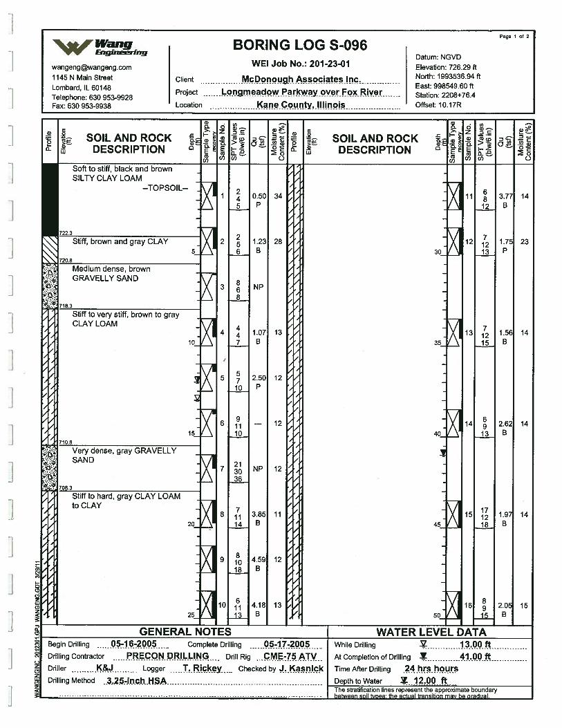
SOIL AND ROCKDESCRIPTION
GENERAL NOTESBegin Drilling 05-16-2005 Complete Drilling 05-17-2005Drilling Contractor PRECON DRILLING Drill Rig CME-75ATVDriller K&J Logger T.Rickey Checked by J.KasnickDrilling Method 3.25.inchH$
SOIL AND ROCKDESCRIPTION
WATER LEVEL DATAWhile Drilling 3.O0.ftAt Completion of Drilling Y 41...0O, ftTime After Drilling .24..rs.hoiIrS
Depth to Water 12.QQ..ft..The stratification Hnes represent the approximate boundary
Page 1 of 2
%/Wang BORING LOG S-096Eng,neeriny
Datum NGVDwangengwangeng.com WEI Job No.: 2012301 Elevation: 726.29 ft1145 N Main Street Client McDonough Associates Inc North: 1993536.94 ft
Lombard IL 60148 East: 998549.60 ft
Telephone: 630 953-9928Project imoadpw.I’rkwayover.F Riv
- Station: 2208+76.4
Fax: 630 953-9938 Location I(aneC.ounty,.!I!iiwis Offset: 10.17R
toSILTY CLAY LOAM
--TOPSOIL--
Stiff to very stiff, brown to grayCLAY LOAM
to CLAY
]
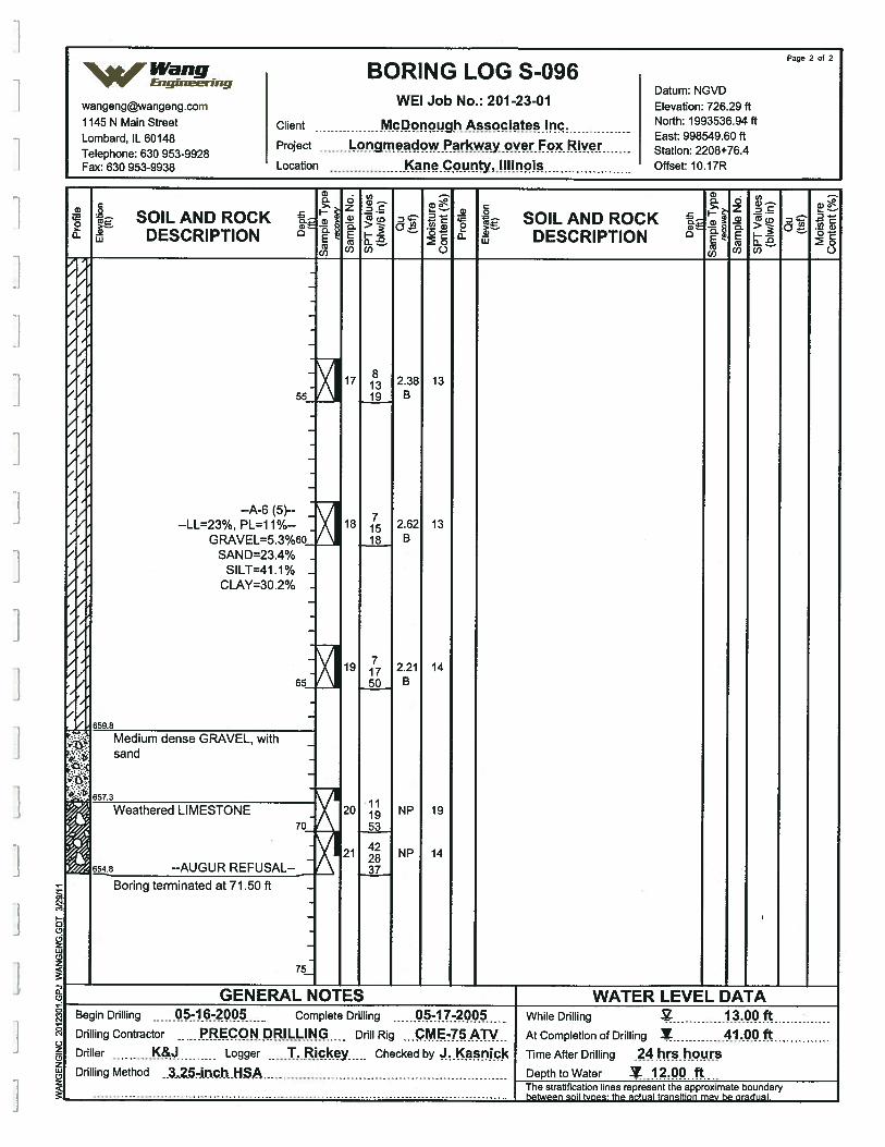
Page 2 of 2
Wang BORING LOG S-096VV’ Engineering
Datum [email protected] WEI Job No.: 201-23-01 Elevation: 726.29 ft1145 N Main Street Client McDonough Associates Inc. North: 1993536.94 ft
L mb rd IL 60148 East: 998549.60 ft
Telephone: 630 953-9928Project fl wayoVer Ep.ive Station: 2208+76.4
Fax: 630 953-9938 Location Kane County, Illinois Offset: 10.17R
a)0ci
C0
>—a)Lu
SOIL AND ROCKDESCRIPTION
p.:ana
a) . a)0. 0 s.-..1LZ .2.5) CPr
— o E. >—e E I——
(6
( (1)0)
0
C-)
a)00.
C0
>—SOIL AND ROCK
DESCRIPTION
1
I
I
55
--LL=23%, PL=11%--GRAVEL=5.3%6Q
SAND=23.4%SILT=41.1%
CLAY=30.2%
65
17
18
19
20
21
2.38B
2.62B
2.21B
NP
NP
13
13
14
19
14
81319
71518
71750
111953
422837
659.8
Medium dense GRAVEL, withsand
.)
ç 770
Weathered LIMESTONE
6548 --AUGURREFUSAL-
Boring terminated at 71.50 ft
75
a,
I 0J ci
(6z(‘ICD
I0
c-I
1 c.)J z
(pzw(2z
GENERAL NOTES WATER LEVEL DATABegin Drilling 056-20 Complete Drilling 05-17-20 While Drilling 3.00 ftDrilling Contractor RECON. II..I-ING - Drill Rig -- .c.ME-75 .ATV. At Completion of Drilling Y 41.00 ftDriller K& Logger T.Rickey Checked by J. Kasn ick TimeAfterDrilling 24Drilling Method 3,25-inch. lISA Depth to Water 12.00. ft
The stratification lines represent the approximate boundary
between
soil types: the actual transition may be gradual.
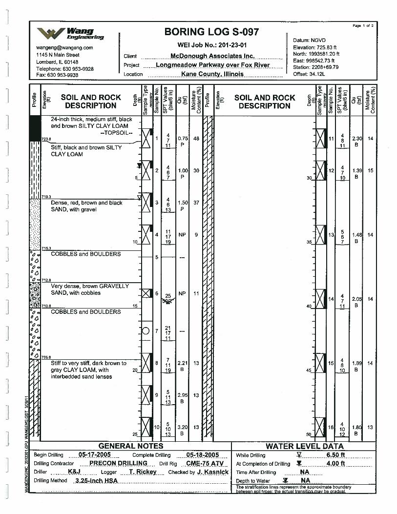
Page 1 of 2
Wang BORING LOG S-097V’V’ Engsneerrng
Datum- NGVDwangengwangeng.com WEI Job No.: 201-23-01 Elevation: 725.83 ft1145 N Main Street Client Mc.Dppugpciateshw. North: 1993581.20 ft
Lombard IL 60148 East: 998542.73 ft
Telephone: 630 953-9928Project WP?YPVer FOX. RIV Station: 2208+69.79
Fax: 630 953-9938 Location Kcy,nois Offset: 34.12L
a, - .
- a,.2. .
SOILANDROCK SOILANDROCKDESCRIPTION DESCRIPTION C
0)0) 0 (0(1) 0
24-inch thick, medium stiff, blackand brown SILTY CLAY LOAM -
--TOPSOIL-
I Stiff, black and brown SILTYCLAY LOAM -
I I
II Q.
, , 71q3
xx
:•:.:: Dense, red, brown and black
SAND, with gravel
.-:-- 10
:•:- 715.3°c COBBLES and BOULDERSCO
0
CO00 712.8
Very dense, brown GRAVELLYSAND, with cobbles
1500 COBBLES and BOULDERSCO0D
CO0
CO
CA‘— 706.8
1 0.75ii P
2 1.007 P
3 1.5013 P
4 NP19
—5———---
6 25 NP
—s 211711
8 2.2119 B
9 . 2.9513 B
10 - 3.2013 B
48
30
37
9
11
13
13
13
30
35
40
45
50
11
12
13
14
15
16
48
11
4710
567
47
11
4810
41012
2.30B
1.39B
1.48B
2.05B
1.89B
1.81B
14
15
14
14
14
13
Stiff to very sff, dark brown togray CLAY LOAM, withinterbedded sand lenses
20
25 -
0
0-4
I 0-4
J z
2LLCr2a
GENERAL NOTES WATER LEVEL DATABegin Drilling 5-17-2005 Complete Drilling 05-18-20 - While Drilling 6..5QftDrilling Contractor PRECON DRILLING Drill Rig .
. .c.M.-75 ATV At Completion of Drilling Y .00 fDriller Logger ickey Checked by Krck Time After Drilling NADrilling Method .3,2.5-in.chNSA Depth to Water A
The stratification lines represent the approximate boundary
between
soil types: the actual transition may be gradual.
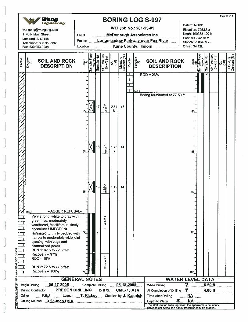
6583 --AUGERREFUSAL-
Very strong, white to gray withgreen hue, moderatelyweathered, fossiliferous, finelycrystalline LIMESTONE,laminated to thinly bedded withnarrow to moderately wide jointspacing, with vugs andchannelized pores.RUN 1: 67.5 to 72.5 feetRecovery = 97%RQD = 19%
RUN 2: 72.5 to 77.5 feetRecovery° 100%
GENERAL N
Page 2 of 2
‘%Wang BORING LOG S-097vv EngineeringDatum NGVD
wangengwangeng.com WEI Job No.: 201-23-01 Elevation: 725.83 ft
1145 N Main Street Client North: 1993581.20 ft
Tephone 630 953-9928Project ngmeadowParkwayov Fox River gg
Fax: 630 953-9938 Location Offset: 34.12L
a)0
0
C0
>.—a)w
SOIL AND ROCKDESCRIPTION
a)0
>‘ zI—a .. -
a’a)—
o.o_
Cl) C)
SOILAND ROCKDESCRIPTION
RQD = 26%
Boring terminated at 77.50 ft
1355
I
I
1
6014
1465 B
80
85
90
95
100
C0RE
I 75
0
CN
0
C-)zC’zUiCDz
Begin Drilling 5-17-2005 Complete Drilling 05-18-2 -
Drilling Contractor PRECON DRILLING - Drill Rig ME-75ATVDrfller K& Logger T. Rickey .. Checked by J.KasnickDrilling Method 3..254n.ch.HSA
WATER LEVEL DATAWhile Drilling 6.50 ftAtCompletionofDrilling 4.00 ftTime After Drilling ADepth to Water N.AThe stratification lines represent the approximate boundaryhntwonn onil funno- iSa art, al trancitinn mat, ha nrarlrral
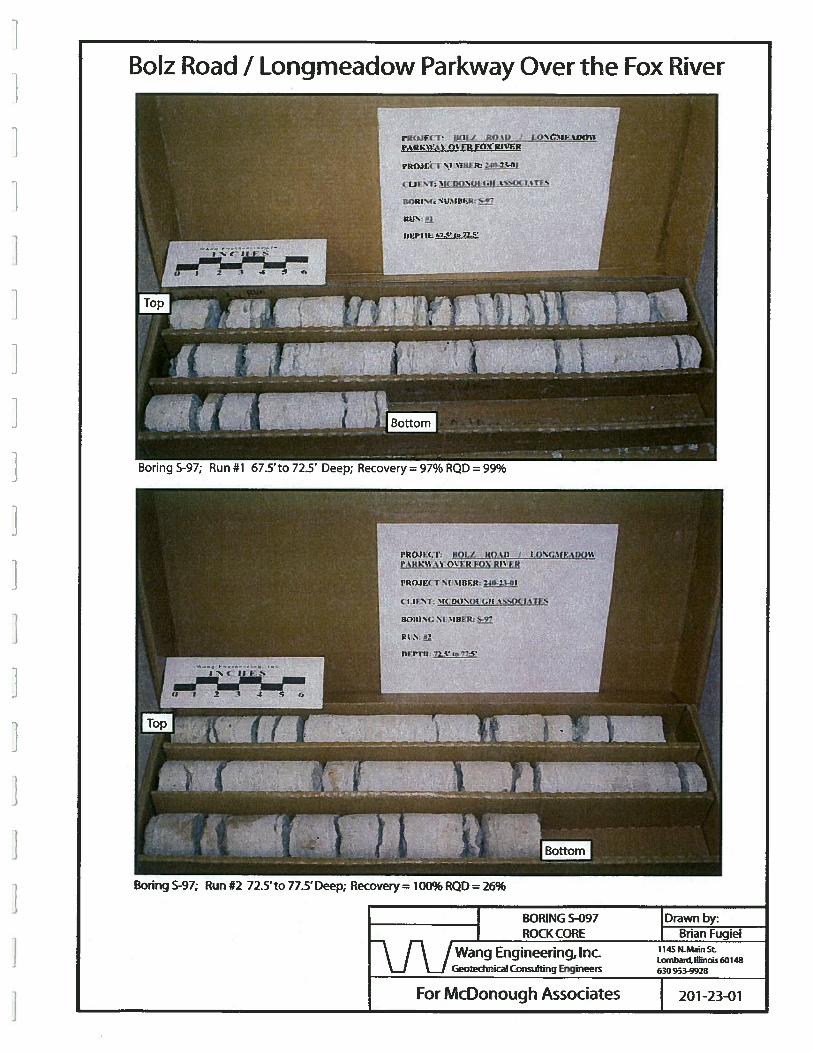
BoIz Road I Longmeadow Parkway Over the Fox River
BORING S-097 Drawn by:ROCK CORE Brian Fugiel
[\ /Wang Engineering, Inc.J L.J Geotedsnical Consulting Engineess 630 953-9923
Boring 5-97; Run #1 ,‘.5’to 72.5’ Deep; Recovery = 97% R
Boring 5-97; Run #2 72.5’ to 77.5’ Deep; Recovery = 100% RQD 26%
For McDonough Associates 201-23-01
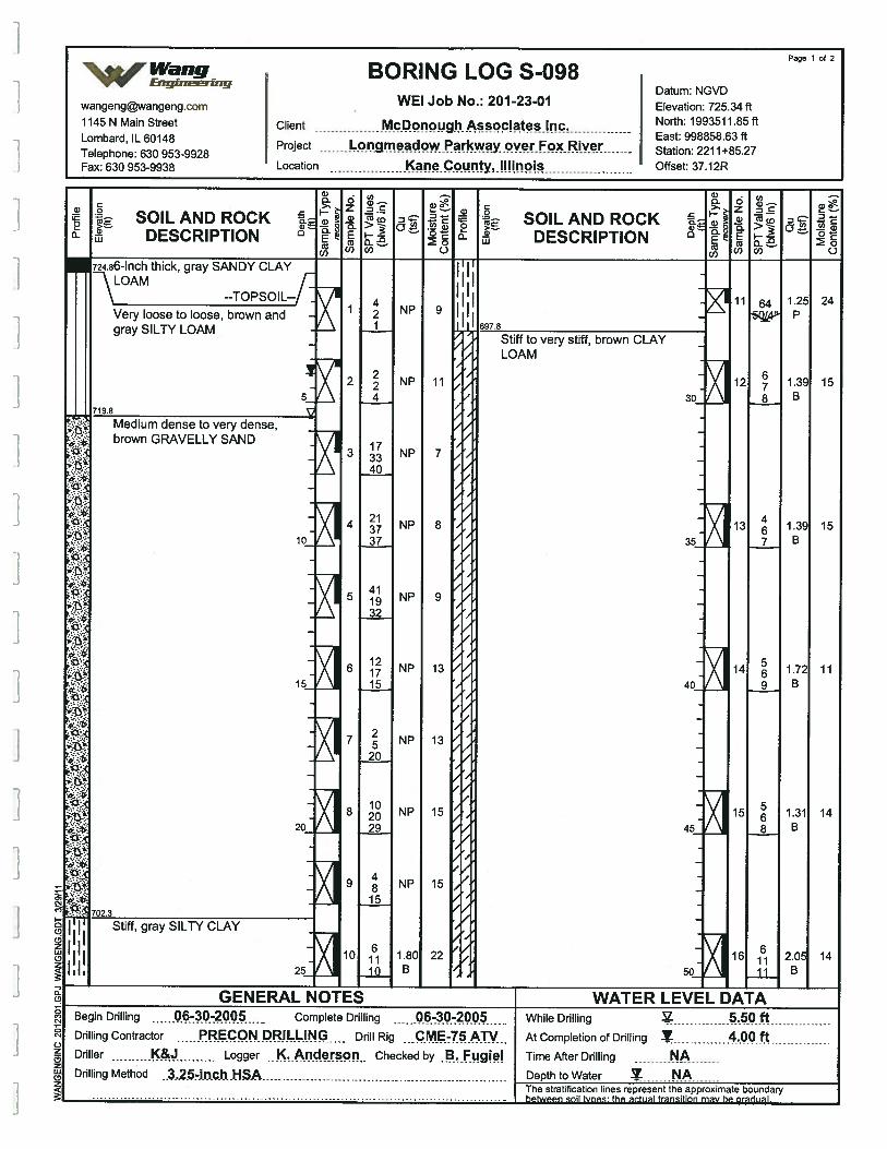
SOIL AND ROCKDESCRIPTION
SOIL AND ROCKDESCRIPTION
Very loose to loose, brown andgray SILTY LOAM
brown GRAVELLY
GENERAL NOTESBegin Drilling -30-2 Complete Drilling -
Drilling Contractor ECONDRI..LIN( Drill Rig ...c.ME-75ATVDriller K& Logger ...Iç.nderspn. Checked by B. FugielDrilling Method ..3..25-inch.H.SA
WATER LEVEL DATAWhile Drilling .50. !.............AtCompletionofDrilling 4.OOftTime After Drilling NA
Page 1 of 2
%Wang BORING LOG S-098VV Engineering
Datum NGVDwangengwangeng.com WEI Job No.: 201-23-01 Elevation: 725.34 ft1145 N Main Street Client McDonough Associates Inc North: 1993511.85 ft
Lombard IL 60148 East: 998858.63 ft
Telephone: 630 953-9928Project nnadqw.Parkway.overF Riv
- Station: 2211+85.27Fax: 630 953-9938 Location qunty,illinois Offset: 37.12R
Iapproximate
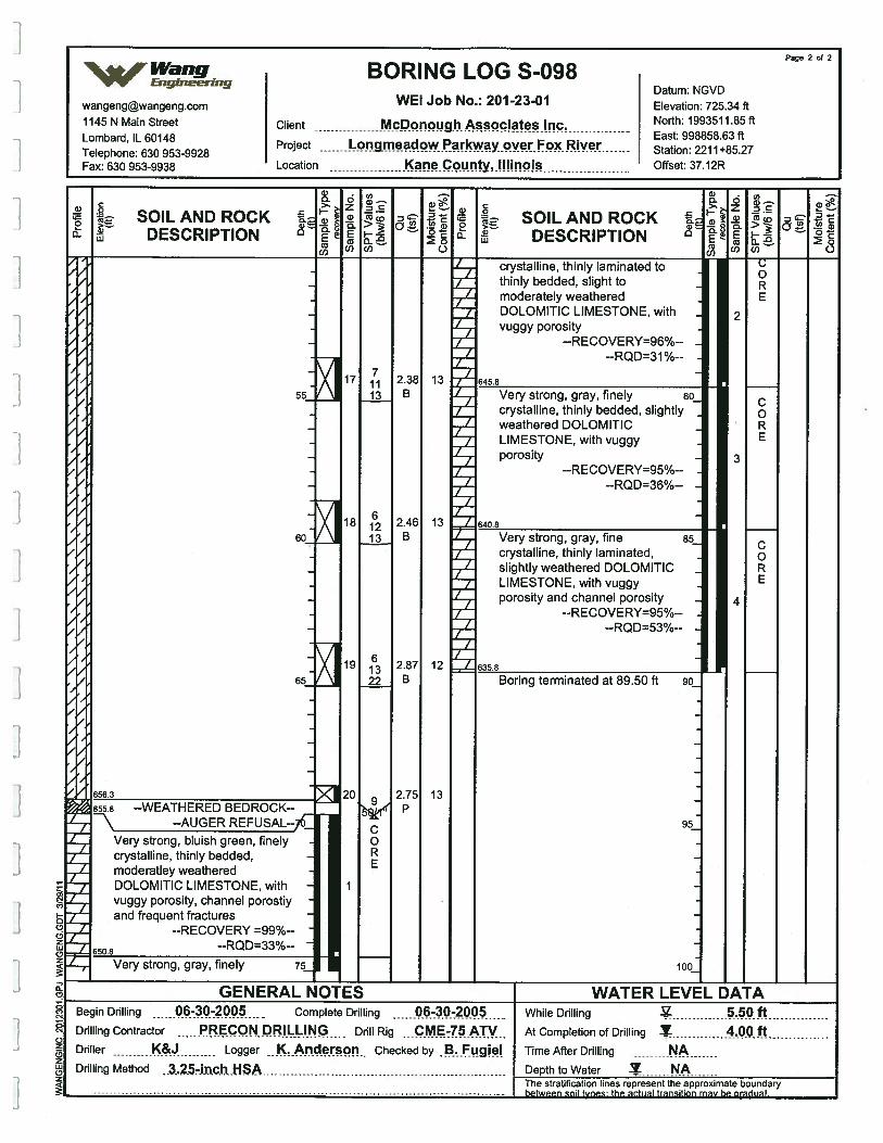
C0RE
C0RE
Page 2 of 2
%Wang BORING LOG S-098Engineering
Datum: NGVDwangengwangeng.com WEt Job No.: 201 2301 Elevation: 725.34 ft1145 N Main Street Client McPonough North: 1993511.85 ft
L b d 1L60148 - - - East:998858.63ft
Telephone: 630 953-9928Project Longmeadow Parkway over Fox RIV Station: 2211+85.27
Fax: 630 953-9938 Location Ky,HIinois Offset: 37.12R
8) - — 8) .
C > Z— a c
t SOILANDROCK SOILANDROCK& DESCRIPTION 0 DESCRIPTION
o) C) COCI) C)
crystalline, thinly laminated tothinly bedded, slight tomoderately weatheredDOLOMITIC LIMESTONE, withvuggy porosity
--RECOVERY=96%--RQDo31%
C;0RE
545.8
/
55
60
65
71113
61213
61322
2
3
4
17
18
19
20
Very strong, gray, finely 80_crystalline, thinly bedded, slightly
Z weathered DOLOMITIC
7 LIMESTONE, with vuggyporosity -
--RECOVERY=95%--Z RQDe36% -
7
540.8
Very strong, gray, fine 85_
crystalline, thinly laminated,7 slightly weathered DOLOMITIC -
LIMESTONE, with vuggyporosity and channel porosity -
--RECOVERY=95%--7 --RQD=53%-- -
2
635.8
2.38B
2.46B
2.87B
2.75P
13
13
12
13658.3
655.8 --WEATHERED BEDROCK-7 --AUGERREFUSAL--767 Very strong, bluish green, finely
crystalline, thinly bedded,2 moderatley weathered
DOLOMITIC LIMESTONE, withvuggy porosity, channel porostiyand frequent fractures
2 --RECOVERY =99%--
5508 --RQD=33%-- -
Boring terminated at 89.50 ft 90_
95
100z
-, Very strong, gray, finely
j
75
C)z(0zUi(0z
GENERAL NOTES WATER LEVEL DATABegin Drilling -30-2 Complete Drilling 06-30-2 - While Drflling 5.Q.!tDrilling Contractor RECON RILLI.NG Drill Rig CME-75ATV At Completion of Drilling Y .OOftDriller K& Logger K.A rson Checked by B Fugiel Time After Drilling ADrilling Method .3..25-inch.HSA Depth to Water Z NA
The stratification lines represent the approximate boundary
between
soil tvDes: tha actual transition may be gradual.
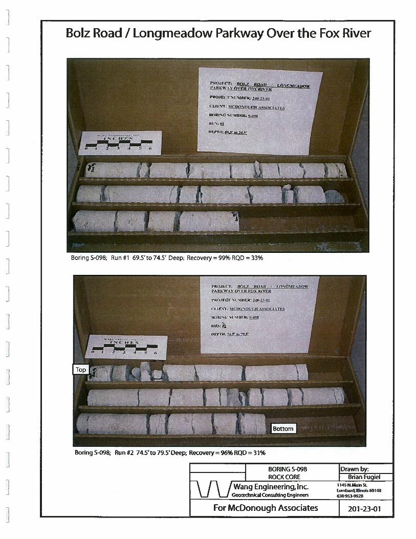
_______________
BORING 5-098 Drawn by:ROCK CORE Brian Fugiel
[\ / Wang Engineering, Inc.L.J ‘Li Geotechnkal Con5utting Engineers 630 953-9928
201-23-01
BoIz Road I Longrneadow Parkway Over the Fox River
Boring 5-098; Run #1 69.5’to 74.5’ Deep; Recovery 99% RQD = 33%
I’I( )3I( T: Rn, RE’. fl :‘.lI . ,u1%
Rk’.’ In IR II.7 III’. :I(
IIIe)II( ‘.1 .III ‘I
I II’I. ‘Jc. in ‘III iI”’(
III IRI (; ‘.1 I II II
In’.
IIFIill
Boring S-098; Run #2 74.5’to 79.5 Deep; Recovery= 96% RQD = 31%
For McDonough Associates
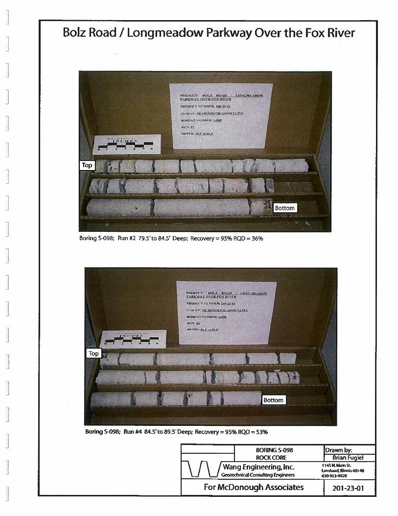
BoIz Road I Longmeadow Parkway Over the Fox River
______________
BORING S-098 Drawn by:ROCK CORE Brian Fugiel
\ f\ /wang Engineering, Inc._J Li Geotechnical Consuitting Engineers 630 953-9928
201-23-01
Boring 5-098; Run #2 79.5’to 84.5’ Deep; Recovery 95% RQD = 36%
Boring 5-098; Run #4 84.5’to 89.5’ Deep; Recovery = 95% RQD = 53%
For McDonough Associates
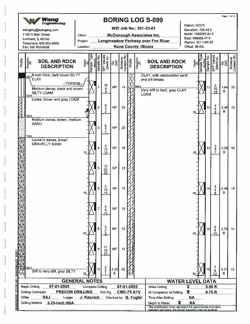
Page I of 2
Wang BORING LOG S-099VV Engineering
Datum NGVDwangengwangeng.com WEI Job No.: 201 -23-01 Elevation: 72644 ft1145 N Main Street Client Mcflonough Associates Inc. North: 1993585.81 ft
Lombard IL 60148 East: 998858.47 ft
Telephone: 630 953-9928Project Lot madow arkway over Fox River Station: 2211+85.55
Fax: 630 953-9938 Location K?no.c.inty,.!!Ii’wis Offset: 36.83L
aor00
SOILAND ROCKDESCRIPTION
-C
C-G)30
a - a -
2 -
k SOILANDROCK. DESCRIPTION
(00) 0 ( (00) 0
CLAY, with interbedded sandI and silt lenses
I I
Very stiff to hard, gray CLAYLOAM
72588-inch thick, dark brown SILTY
\ CLAY
\ --TOPSOIL--
Medium dense, black and brown -
SILTY LOAM723.4
-. Loose, brown and gray LOAM
-: 720.9
Medium dense, brown, medium -
SAND
718.4
Loose to dense, brownGRAVELLY SAND
10
15
:-20
0)03
COCO
702.2
Stiff to very stiff, gray SILTY25
2
3
4
5
6
7
8
9
10
1664
622
677
41514
122220
51211
49
11
323
111823
357
14
25
20
18
13
10
18
15
12
22
NP
NP
NP
NP
NP
NP
NP
NP
NP
2.25B
F
F
F
21618
469
367
356
5810
7912
11
12
13
14
15
16
30
35
40
45
50
25
13
14
14
14
13
1.64B
2.46B
2.38B
2.46B
2.7fiB
3.77B
GENERAL NOTES — WATER LEVEL DATABegin Drilling 7.-O1-20Q.5 Complete Drilling -01-2 While Drilling 5.50 ftDrilling Contractor REcON.PRIL.LI.NG Drill Rig
.çME-7.5ATV At Completion of Drilling Y 475ft
Driller Logger •1asnic Checked by .B.Fugiei Time After Drilling NADrilling Method
. .3..25-In.c.h.}ISA Depth to Water NAThe stratification lines represent the approximate boundary
between
soil types the actual transition may be gradual.
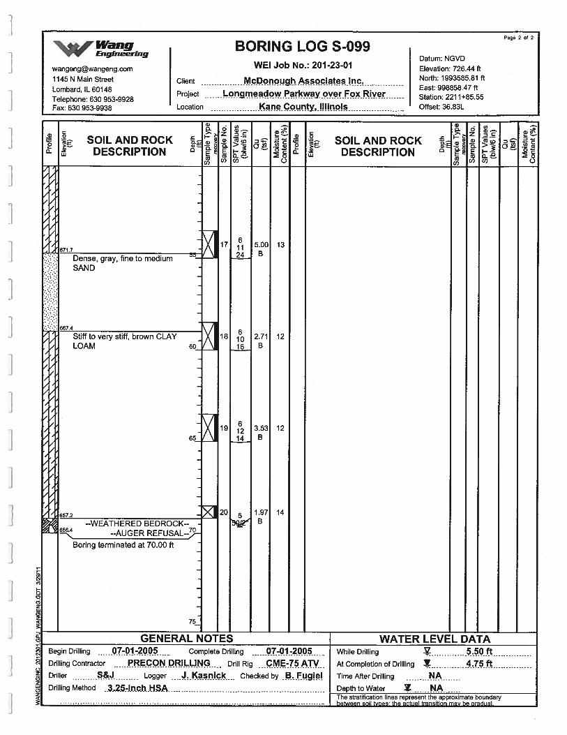
Page 2 of 2
Wang BORING LOG S-099vv’ EngineeringDatum NGVD
wangeng©wangeng.com WE! Job No.: 201-23-01 Elevation: 726.44 ft1145 N Main Street Client McDonough Associates Inc. North: 1993585.81 ft
L b d IL 60148 East: 998858.47ft
T&ephone: 630 953-9928Project ongmeadow Parkway over Fox Rive Station: 2211+85.55
Fax: 630 953-9938 Location Kounty,INinois Offset: 36.83L
a)0
C0
>—a,w
SOIL AND ROCKDESCRIPTION
-c
0)0
a,a)> -
a). ,Esa)
(I)
oza)a)B(2
U)
0,
(0>—
C/)
a) a)—
C)
a)to0
C0
CU—>.—tlt
Ui
SOIL AND ROCKDESCRIPTION
.0
a))0
t71.7::: Dense, gray, fine to medium::.-,:::
SAND
‘:.: 667.4
Stiff to very stiff, brown CLAYLOAM
17
18
19
20
I
/
/
F
I
5.0024 B
2.7116 B
3.5314 B
1.97B
13
12
12
14
60
65
657.2
--WEATHERED BEDROCK-- -
--AUGER REFUSAL--9-
Boring terminated at 70.00 ft
C,CN
1I
C:,(2z
Ui(2z
I_J U-
(2
]C,,
(N
0z
(2z
a)(2z
GENERAL NOTES WATER LEVEL DATABegin Drilling 07-01-2 Complete Drilling 07-01-2005 - While Drilling 55 fDrilling Contractor PRECON DRILLING Drill Rig CME-75ATV At Completion of Drilling .75 ftDriller Logger J.Kas nick Checked by B. Fugiel Time After Drilling NADrilling Method 3.25-inch HSA Depth to Water NA
The stratification lines represent the approximate boundary
between
soil ft/Des- the actual transition may be gradual.
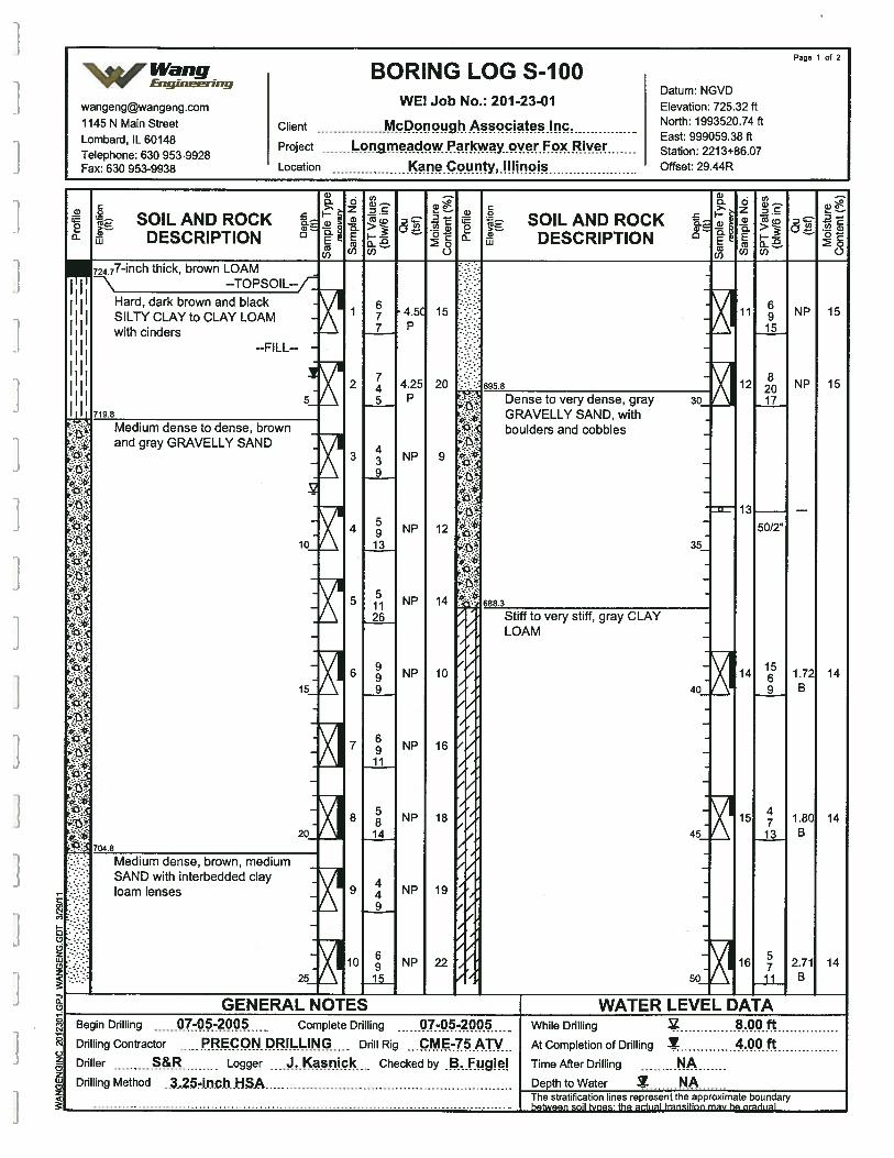
GENERAL NOTES
:.
p
:
Begin Drilling 07-05-2005 Complete Drilling 07-05-2005Drilling Contractor P RECON DRILLING Drill Rig CME-75ATVDriller S&R Logger J.Kasnick Checked by .8fugie!
WATER LEVEL DATAWhile Drilling 8.00 ftAt Completion of Drilling Y 400 ftTime After Drilling NADepth to Water N.A
Page 1 of 2
Wang BORING LOG S-100‘vv Eagrneerrng
Datum NGVDwangeng©wangeng.com WEI Job No.: 201 -23-01 Elevation: 725.32 ft1145 N Main Street Client cDonough Associates Inc North: 1993520.74 ft
Tephone: 630 953-9928Project me?c.q?i1cw Y.OV Fve Station: 221 3+867
Fax: 630 953-9938 Location Kane C unty,.II!Inpjs Offset: 29.44R
CD
.0
0
--TOPSOIL--
C0a—>.—.a)
LU
SOILAND ROCKDESCRIPTION
•I I Hard, dark brown and black
SILTY CLAY to CLAY LOAMwith cinders
--FILL--
15
719.8
SOIL AND ROCKDESCRIPTION
Dense to very dense, grayGRAVELLY SAND, withboulders and cobbles
5
Medium dense to dense, brownand gray GRAVELLY SAND
20 695.8
15
9
15
10
1235
14 688.3
15
Stiff to very stiff, gray CLAYLOAM
10
16
1440
20
18
SAND with interbedded clayloam lenses 19
45
14
25
22
Drilling Method ..3,25-inch.HSA
50
14
The stratification lines represent the approximate boundaryhotwoon cnil h,nnc tho ontriol troncitinn may ho nrartiral
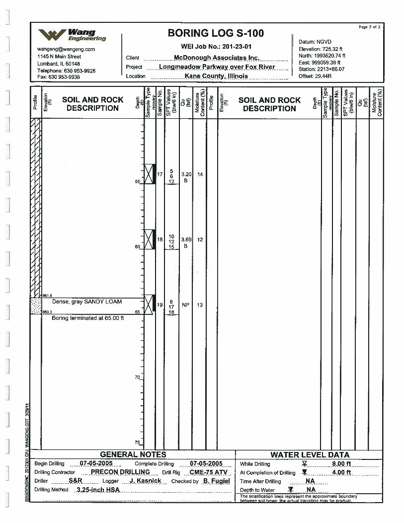
Page 2 of 2
‘S,s Wang BORING LOG S-100VV Engineering
Datum: NGVDwangengwangeng.com WEI Job No.: 201-23-01 Elevation: 725.32 ft1145 N Main Street Client McDonoughAssociatesi.nc North: 1993520.74 ft
L b ... East: 999059.38ft
T&ephone: 630 953-9928Project rigim adow yover Fox Riv Station: 2213+86.07
Fax: 630 953-9938 Location Kane County, I!Iinois Offset: 29.44R
s- .
c . C .
i SOILANDROCK SOILANDROCKDESCRIPTION DESCRIPTION a
F
F
F
/
/
/
55
60
14
12
13
17 3.2012 B
18 369
15 B
19 NP
18
661.6
Dense, gray SANDY LOAM
.•.: 660.3 65Boring terminated at 65.00 ft
70
75.
0(2 GENERAL NOTES WATER LEVEL DATA
Begin Drilling 07-05-200 Complete Drilling 07-05-2 While Drilling 8..Q.Q.ftDrilling Contractor PRECON DRILLING Drill Rig . .C M7.5 ATV At Completion of Drilling Y 4.0.0. ftDriller S&R Logger J. Kasnick Checked by .B...Fugie.I Time After Drflling NADrilling Method ..3,25-i.n.ch.HSA Depth to Water A
The stratification lines represent the approximate boundary
between
soil Woes: the actual transition may be gradual.
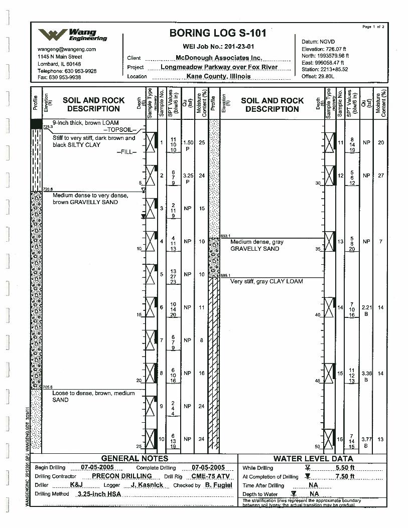
Page 1 of 2
%Wang BORING LOG S-1O1VV Engineering
Datum NGVD
wangengwangeng.com WEI Job No.: 201-23-01 Elevation: 726.07 ft1145 N Main Street Client McPughAssociates!nc North: 1993579.98 ft
Lomb d IL 60148 East: 999058.47 ft
Telephone: 630 953-9928Project m?4W.arkw?y.cWei-.Fox Rive Station: 221 3+85.52
Fax: 630 953-9938 Location Ic9W1tY,.N!1flOiS Offset: 29.80L
-.—. a)
.
a .
k SOILANDROCK SOILANDROCK& DESCRIPTION DESCRIPTION E
coco C) COO) 0
9-inch thick, brown LOAM--TOPSOIL--/
Stiff to very stiff, dark brown andblack SILTY CLAY
--FILL--
57206
Medium dense to very dense,brown GRAVELLY SAND
30.
692.1
10
15
20
; Medium dense, grayGRAVELLY SAND 35
)
.‘0)‘ 689.1
2
3
4
5
6
7
8
9
10
111010
679
2119
41113
132723
101420
679
61016
244
613ii
1.50P
3.25P
NP
NP
NP
NP
NP
NP
NP
NP
25
24
15
10
10
11
8
16
24
24
Very stiff, gray CLAY LOAM
11
12
13
14
15
16
81419
5612
58
20
71016
111213
714
NP
NP
NP
2.21B
3.3€B
3.77B
20
27
7
14
14
13
705.6
Loose to dense, brown, mediumSAND
40
45
50
a(0
j
25
0
0
C.)z(LIz0CDz
GENERAL NOTES WATER LEVEL DATABegin Drilling 07-05-20Q,5 - Complete Drilling 07-05-2005 While Drilling 5Q.ftDrilling Contractor PRECON DRILLING Drill Rig At Completion of Drilling 7,5QftDriller K&J Logger J. Kas nic Checked by B. FLigiel Time After Drilling NADrilling Method ..3..25-lnchilSA Depth to Water 2 N.A
The stratification lines represent the approximate boundary
between
soil types: the actual transition may be gradual
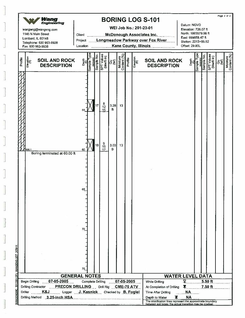
q0
(N
0(N
C)z0zUI(2z
Page 2 of 2
Wang BORING LOG S-1O1v’v Enguwerrng
Datum: NGVD
wangengwangeng.com WEI Job No.: 201-23-01 Elevation: 726.07 ft
1145 N Main Street Client MçPqnoug.hAciatesjric North: 1993579.98 ft
Tephone: 630 9539928Project ndowParkwayoverF RIV Station: 221 3+8S52
Fax: 630 953-9938 Location Kane County, !!Iinois Offset: 29.80L
SOILAND ROCKDESCRIPTION
SOIL AND ROCKDESCRIPTION
666.1
5513
Boring terminated at 60.00 ft
13B
65
70
75
j
GENERAL NOTES WATER LEVEL DATABegin Drilling 07-05-20 - Complete Drilling 07-05-2005 While Drilling 5.QftDrilling Contractor RECON DRILLING Drill Rig ME-75ATV AtCompletionofDrilling Y .5Q.ftDriller K& Logger J.Kasnic Checked by B. Fugiel Time After Drilling NADrilling Method .3..25-i.nc.h.NSA Depth to Water N.A
The stratification lines represent the approximate boundary
between
soil tvoes: the actual transition may be gradual.
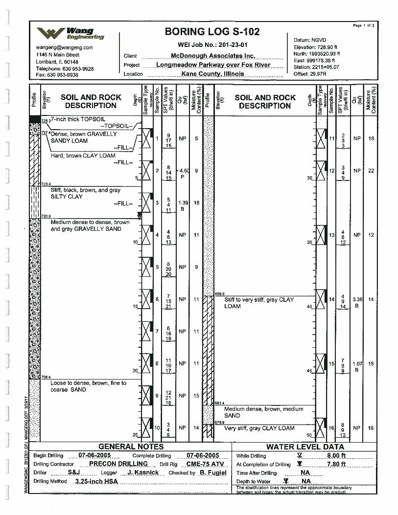
72837-inch thick TOPSOIL--TOPSOIL--f
?4Dense, brown GRAVELLY\SANDY LOAM -
\ —FILL--
Hard, brown CLAY LOAM
5
Stiff, black, brown, and gray -
II SILTY CLAY
I I --FILL-- -
II 720.9
: Medium dense to dense, brownand gray GRAVELLY SAND -
15
20_
708.4
Loose to dense, brown, fine tocoarse SAND
Stiff to very stiff, gray CLAYLOAM
Page 1 of 2
% Wang BORING LOG S-102VV Engineering
Datum NGVDwangengwangeng.com WE! Job No.: 2012301 Elevation: 72890 ft1145 N Main Street Client McDonough Associates Inc North: 1993520.93 ft
Lombard IL 60148 East: 999178.38 ft
Telephone: 630 953-9928Project aclow Parkway over F RIV
- Station: 221 5+05.07
Fax: 630 953-9938 Location neCointy,IIIinois Offset: 29.97R
a) . —Cl)
C j.ESOILANDROCK L SOILANDROCK
DESCRIPTION DESCRIPTION 0 2COO) C) 0)0) C)
--FILL--
723.4
30
35
2
3
4
5
6
7
8
9
10
NP
4.5’P
1.39B
NP
NP
NP
NP
NP
NP
NP
91715
81415
5411
4613
82020
71521
61619
111017
122118
349
5
9
18
11
9
11
11
11
15
14
689.9
11
12
13
14
15
16
NP
NP
NP
3.36B
1.07B
NP
233
349
4812
49
14
789
89
-II
18
22
12
14
15
16
40
45
a(0
681.4
25
a
0
C-)zCDz0(0
::. Medium dense, brown, medium.::::: SAND.:: 679.9
Very stiff, gray CLAY LOAM50
GENERAL NOTES WATER LEVEL DATABegin Drilling 07-06-2 Complete Drilling 07-06-200 While Drilling 8.Q.OftDrilling Contractor PREcON.PR!L..I_I.Nc Drill Rig CME-75ATV At Completion of Drilling Y .BOftDriller Logger J.Kasnic Checked by B. Fugiel Time After Drilling ADrilling Method ..3..2.54n.chHSA Depth to Water NA
The stratification lines represent the approximate boundary.- between soil tvoes: the actual transition may be gradual
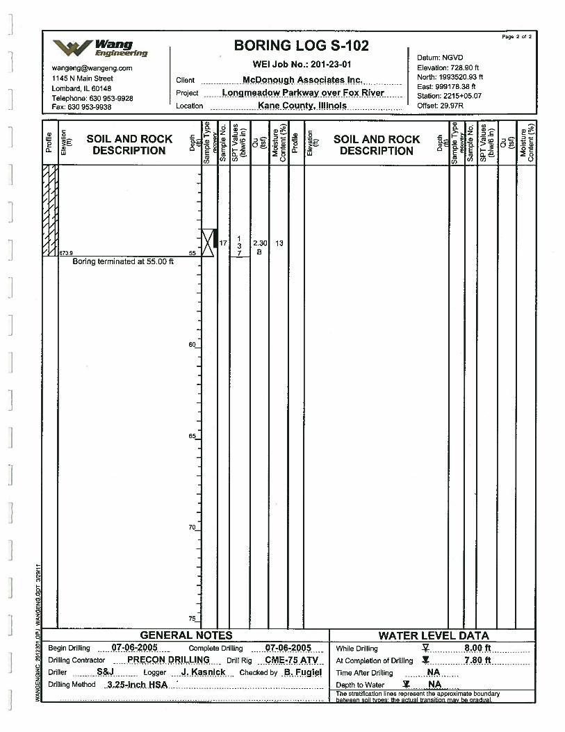
Page 2 of 2
Wang BORING LOG S-102V’V Engineering
Datum NGVDwangengwangeng.com WEI Job No.: 201-23-01 Elevation: 728.90 ft
1145 N Main Street Client McDonough Associates Inc. North: 1993520.93 ft
T&ephone: 630 953-9928Project Lopgmeadow Parkway over Fox River 2215+05 07
Fax: 630 953-9938 Location Kcunty,IiIinois Offset: 29.97R
SOILAND ROCK° DESCRIPTION
a,a—DCa
U)
cD
o.
0
6)
0
0
C0
>.—a
LU
SOIL AND ROCKDESCRIPTION
673.9
Boring terminated at 55.00 ft
2.30B
13
60
65
70
75
00
j0
c-I0
C.)z0zLI)02
GENERAL NOTES WATER LEVEL DATABegin Drilling 7-06-2 Complete Drilling 07-06-200 - While Drflhing 8.00 ftDrilling Contractor EcQN.PRJL.L.JNG Ddll Rig ...c.M.E45ATV At Completion of Drilling Y .80 ftDriller Logger JKasriic Checked by .B.Fugie! Time After Drilling NADrilling Method
. .3..2-i.n.chkiSA Depth to Water NAThe stratification lines represent the approximate boundary
between
soil Woes: the actual transition may be gradual.
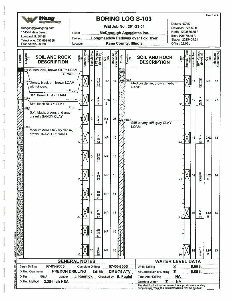
Page 1 of 2
Wang BORING LOG S-103v”v Eng,neering
Datum NGVDwangengwangeng.com WEI Job No.: 2012301 Elevation: 728.83ff
1145 N Main Street Client McPonough Associates Inc North: 1993580.85 ft
Lombard IL 60148 East: 999178.46 ft
Telephone: 630 953-9928Project y.o.er Fox Riv
- Station: 221 5+05.51
Fax: 630 953-9938 Location Iounty,.Illinois Offset: 29.95L
a a.
.
k SOILANDROCK . SOILANDROCKDESCRIPTION
. DESCRIPTION(1)0) C.) (Ott) 0
728.36-inch thick, brown SILTY LOAM--TOPSOIL--f
8Dense, black anf brown LOAM
\ with cinders--FILL-- -
Stiff, brown CLAY LOAM724.6 FILL-
Stiff, black SILTY CLAY S723.3 --FILL--
Soft, black, brown, and graygravelly SANDY CLAY
K
720 8
:: Medium dense, brown, mediumSAND
;: 30
.: 696.8
VMedium dense to very dense,brown GRAVELLY SAND
Stiff to very stiff, gray CLAYLOAM
2
3
4
5
6
7
8
9
10
111515
467
347
71013
132027
91313
101821
111617
202437
81318
NP
1.56B
0.41B
NP
NP
NP
NP
NP
NP
NP
14
13
26
12
11
13
11
16
10
10
10
15
20
25
11
12
13
14
15
16
161116
71215
71114
81012
5810
71513
NP
NP
2.62B
3.20B
1.64B
1 .9B
18
27
13
14
14
13
35
40
45
50
GENERAL NOTES — WATER LEVEL DATABegin Drilling 07-O52OO5 Complete Drilling Q.T-Q6.-2.Q.O.5 While Drilling 8.00 ftDrilling Contractor RECON DRILLING - Drill Rig CME-75 ATV At Completion of Drilling 6.8.0.ftDriller K& Logger Checked by BFugiei Time After Drilling NADrilling Method ..3..25-i.n.ch..HSA Depth to Water Z N.A
The stratification lines represent the approximate boundarybetween soil types; the actual transition may be produal.
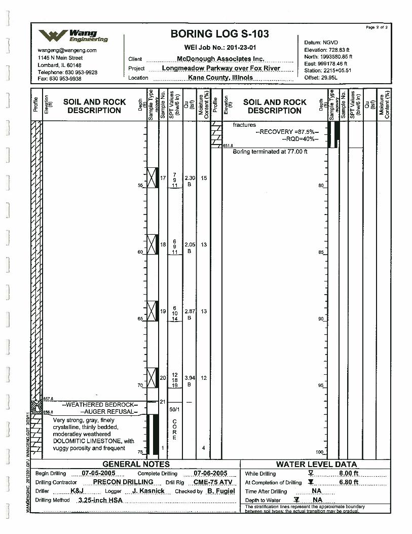
page 2 of 2
Wang BORING LOG S-103Engineering
Datum NGVDwangengwangeng.com WEI Job No.: 201-23-01 Elevation: 72883 ft1145 N Main Street Client McDonough Associates Inc North: 1993580.85 ft
Lombard IL 60148 East: 999178.46 ft
Telephone: 630 953-9928Project r wParkway,c.Rive Station: 221 5+05.51
Fax: 630 953-9938 Location wccuntY,.!Iinois Offset: 29.95L
a)00
C0
>.—,0)
UI
SOIL AND ROCKDESCRIPTION
a)0. 0
I ..E
(0
C)
C0
>:.0)
Ui
SOIL AND ROCKDESCRIPTION
fractures
.0
0
a)0.>“
a)Cl)
dz‘1)0.E(a
Cl)
05
C)
351.8
--RECOVERY =87.5%----RQD=40%-- I
Boring terminated at 77.00 ft
15
7
7,
/
/
7
/
/
13
13
80
85
90
95
100
657.8
656.8
12
--WEATHERED BEC--AUGER REFUSAL--
I Very strong, gray, finelycrystalline, thinly bedded,moderatley weatheredDOLOMITIC LIMESTONE, withvuggy porosity and frequent
IGENERAL NOT
C
C.)zC)zUIC)z
4
Begin Drilling 07-05-2005 Complete Drilling 07-06-2 While Drilling .Q.Q.ftDrilling Contractor PRECONDRILLI.N.G - Drill Rig ...PM.E-7.5.ATV.. At Completion of Drilling .8.0.fDriller K& Logger J.Kasn ic Checked by .BfLgie! Time After Drilling NADrilling Method .3.25-inch HSA Depth to Water NA
The stratification lines represent the approximate boundary
between
soil tvoes the actual transition may be gradual
WATER LEVEL DATA
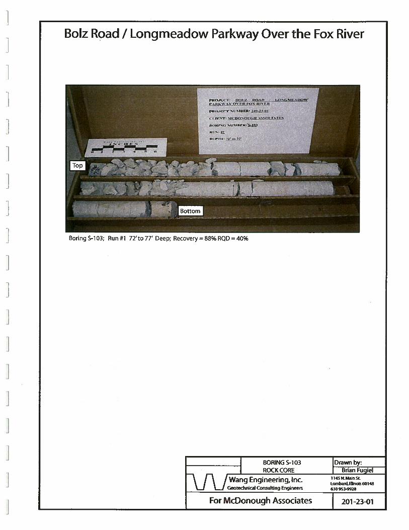
BoIz Road I Longmeadow Parkway Over the Fox River
I BORING S-i 03 I Drawn by:
I ROCK CORE Brian Fugiel1145 NMain StWang Engineering, Inc.
Geotechriical Consulting Engineers 630 953-9928
201-23-01
riioflCT: 8O(Z ROAfl(nrc rcrçfjg
tKOJICT Ni %iUFR p-i
C i)t’T: jflQN( 3jft W.%(K i
no,cra: %t ‘flu K:
Boring S-i 03; Run #1 72’ to 77’ Deep; Recovery = 88% RQD = 40%
For McDonough Associates
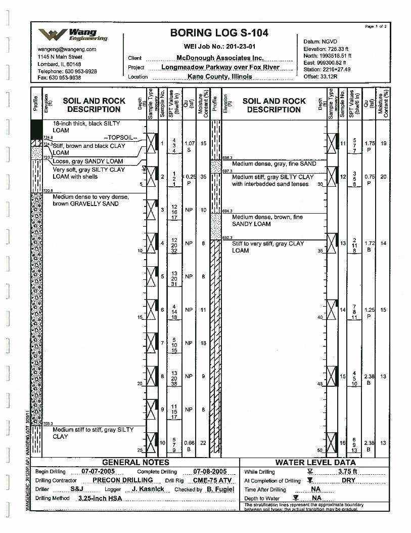
Page 1 of 2
‘%Wang BORING LOG S-104‘VV Engineering
Datum NGVDwangeng©wangeng.com WEI Job No.: 201 2301 Elevation: 726.33 ft1145 N Main Street Client McponpugliAsspciates Inc. North: 1993518.51 ft
Lombard IL 60148 East: 999300.82 ft
Telephone: 630 953-9928Project nmeadow Parkway over FocRive Station: 221 6+27.49
Fax: 630 953-9938 Location Kanç.county,jpinois Offset: 33.12R
w__ s,____
SOILANDROCK SOILANDROCK°- DESCRIPTION DESCRIPTION
. 03(1) C) (1)0) C)
18-inch thick, black SILTYLOAM
7248 --TOPSOIL-
7243Stiff, brown and black CLAY\LOAM
II
I
5
Loose, gray SANDY LOAM
Very soft, gray SILTY CLAYLOAM with shells
720.8
Medium dense to very dense,brown GRAVELLY SAND
597.3
Medium dense, gray, fine SAND
Tp Medium stiff, gray SILTY CLAYI I with interbedded sand lenses 30_
[jj 694.3
:- Medium dense, brown, fine
: SANDY LOAM
. :: 692.3
KK
KStiff to very stiff, gray CLAYLOAM
2
3
4
5
6
7
8
9
10
434
2
121617
122032
132031
41418
51015
132038
111517
579
1.07S
0.2P
NP
NP
NP
NP
NP
NP
NP
0.66B
15
35
10
8
8
11
18
9
8
22
10
15
20
11
12
13
14
15
16
577
358
2118
78
11
4510
69
1.75P
0.75P
1.72B
1.25P
2.38B
2.38B
19
20
14
15
13
13
35
40
45
50
Medium stiff to stiff, gray SILTYCLAY
0(p
-j
25
a01
0
C-)
Coz0(2
GENERAL NOTES WATER LEVEL DATABegin Drilling 07-07-2 . Complete Drilling -08-2005 - While Drilling 3.75 ftDrilling Contractor PRECON DRILLING Drill Rig CME-75ATV AtCompletionofDrilling DRYDriller Logger sick Checked by .•fug Time After Drilling NADrilling Method .32.5-inch.HSA Depth to Water N.A
The stratification lines represent the approximate boundary- between sail Woes: the actual transitian may be oradual
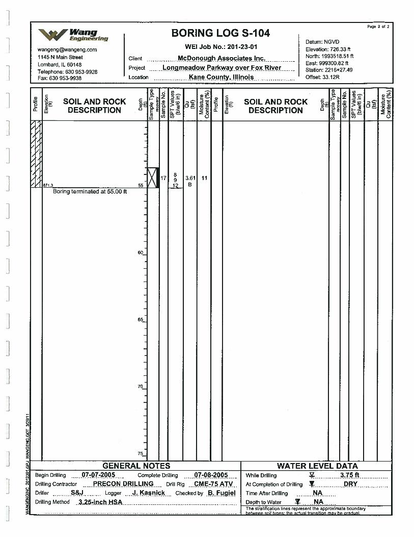
a0
Page 2 of 2
%.Wang BORING LOGS-104V’V’ Engineering
Datum: NGVD
wangengwangeng.com WEI Job No.: 201-23-01 Elevation: 726.33 ft
1145 N Main Street Client McDonou9h Associates Inc. North: 1993518.51 ft
Tephone: 630 953-9928Project•ir Stati 221 6+27 49
Fax: 630 953-9938 Location l(?ne.c.9.u.nty,.!Hiripis Offset: 33.12R
6)a 0>‘- zC
0
>.—a)
U.)
SOIL AND ROCKDESCRIPTION
U)
CO
a0
1205
C)
C0
cv>—a
uJ
SOIL AND ROCKDESCRIPTION
,
F
I
‘ 671.3
Boring terminated at 55.00 ft
3.61B
11
60
65
70
75
0.CD
C
Cs
I C
JCr2IL
2a)
GENERAL NOTES WATER LEVEL DATABegin Drilling 07-Q7-ZQQ.5 Complete Drilling 07-08-2005 While Drflhing 3.75.ftDrilling Contractor PRECON DRILLING Drill Rig CME-75ATV At Completion of Drilling DRYDriller Logger snic Checked by .B.fgie! Time After Drilling NADrilling Method i3..2.57jfl.C.h..HSA Depth to Water A
The stratification lines represent the approximate boundary
between
soil Pipes: the actual transition may be gradual.
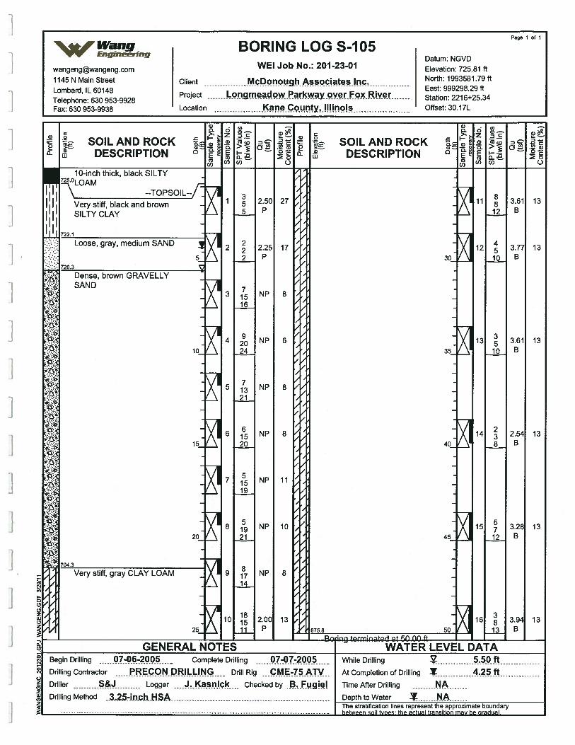
Page 1 of 1
% Wang BORING LOG S-105V•V EngJ.sring
Datum NGVDwangengwangeng.com WEI Job No.: 201-23-01 Elevation: 725.81 ft
1145 N Main Street Client McPonpu9hApciates.Iilc North: 1993581.79 ft
L b d 1L60148 East:999298.29ft
Telephone: 630 953-9928Project 0 wParkwayoverFoc..River Station: 2216+25.34
Fax: 630 953-9938 Location Icne.county,jPjnqis Offset: 30.17L
5— . ;—— - C’)
C’) > Z D ES— C
t SOILANDROCK SOILANDROCKDESCRIPTION DESCRIPTION U
—Ci)(I) 0 ff701) C)
10-inch thick, black SILTY725.0
--TOPSOIL-fVery stiff, black and brownSILTY CLAY
722.1
Loose, gray, medium SAND
5720.3
Dense, brown GRAVELLYSAND
ci
ci.
ci
ci
15
:
ci
20
704.3
Very stiff, gray CLAY LOAM
25
1 2.505 P
2 2.252 P
3 NP16
4 NP24
5 NP21
6 NP20
7 NP19
8 NP21
9 . NP14
10 2.00ii P
27
17
8
6
8
8
11
10
8
13
30
35
40
45
50
11
12
13
14
15
16
8812
4510
3510
238
5712
3813
3.61B
3.77B
3.61B
2.54B
3.28B
3•94
B
13
13
13
13
13
13
C’U:0
(N
0(N
0z(0zLUCOz
emR‘NC’ Ufl or) cC’
GENERAL NOTES — — — WATER LEVEL DATA — —
Begin Drilling 07-06-200 - Complete Drilling 07-07-200 - While Drilling.
5.50 ftDrilling Contractor PRECON DRILLING Drill Rig
.. .PMZ5 .ATV At Completion of Drilling Y 4.25 fDriller S&J Logger asnic Checked by B. Fugiel Time After Drilling NADrilling Method .3.25-inc.h.HS Depth to Water A
The stratification lines represent the approximate boundary
between
soil tyges: the actual transition may be gradual.
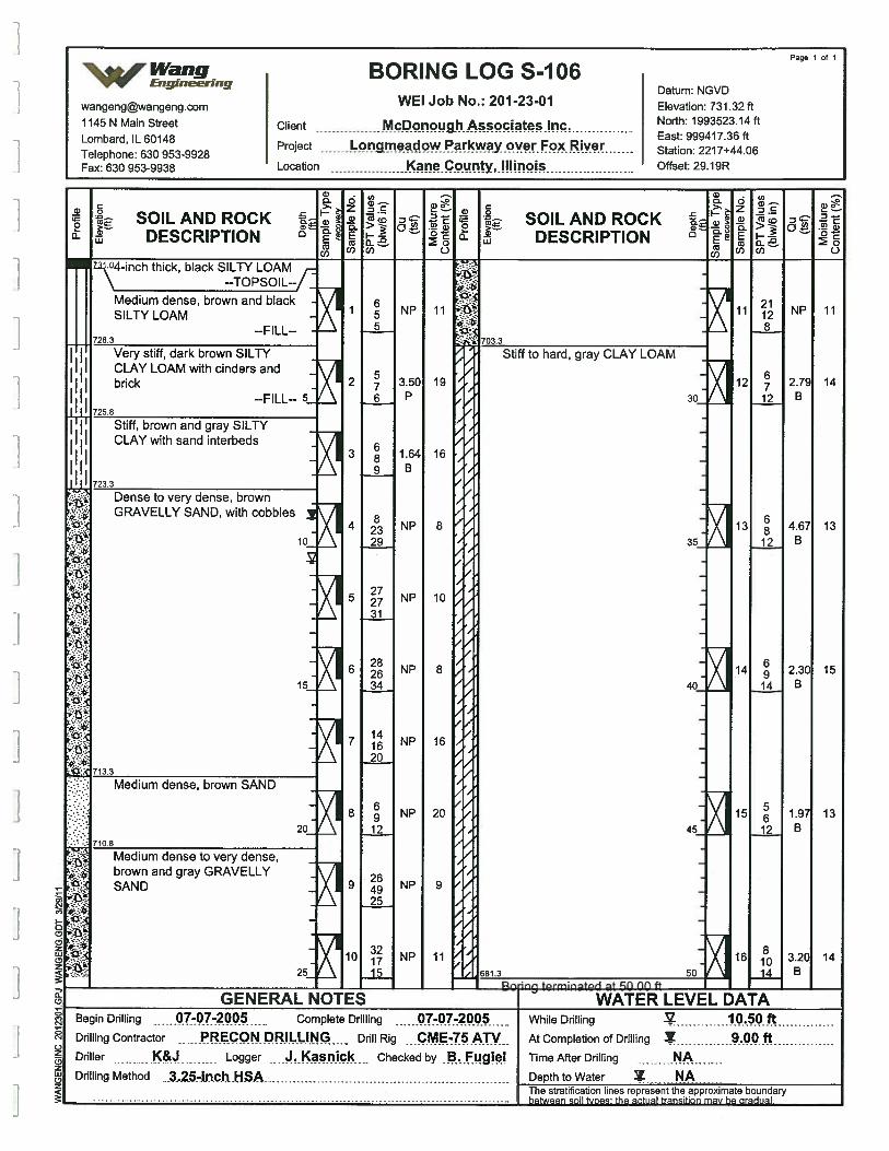
SOIL AND ROCKDESCRIPTION
GENERAL NOTESBegin Drilling 07-07-2005 Complete Drilling -07-200Drilling Contractor PRECON DRILLING Drill Rig ...c.M-Z5ATVDriller K& Logger casnic Checked by •aFugieDrilling Method 3.25-inch HSA
SOIL AND ROCKDESCRIPTION
WATER LEVEL DATAWhile Drilling
AtCompletionofDrilling Y .00 ftTimeAfterDrilling NADepth to Water N
represent the approximate boundary
Page 1 of 1
Wang BORING LOG S-106V Enganeenng
Datum NGVDwangengwangeng.com WEI Job No.: 201-23-01 Elevation: 731.32 ft1145 N Main Street Client McP.onough Assocjate Inc - North: 1993523.14 ft
Project meadow Pikw Fcx.Riv Station: 2217+44X16
Fax: 630 953-9938 Location Kane C unty,.!!!inpjs Offset: 29.19R
Dense to very dense, brownGRAVELLY SAND, with cobbles
urn dense to very dense,brown and gray GRAVELLYSAND
]
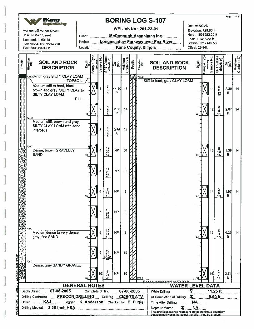
Page 1 of 1%jWang BORING LOGS-107
vv’ EngineeringDatum’ NGVD
wangeng©wangeng.com WEI Job No.: 201-23-01 Elevation: 729.66 ft1145 N Main Street Client McDonough. Associates North: 1993582.29 ft
L b d lL60148 East:999418.53ft
Telephone: 630 953-9928Project ?Y°”I Station: 221 7+45.58
Fax: 630 953-9938 Location Kounty,Illinois Offset: 29.94L
6).
—. COC . .
i- SOILANDROCK I,- SOILANDROCKDESCRIPTION DESCRIPTION . ‘‘
—02(/) C) (0(I) C)
729.26-inch gray SILTY CLAY LOAM 704.2
--TOPSOIL--f Stiff to hard, gray CLAY LOAM
‘I Medium stiffto hard, black, 7 5I brown and gray SILTY CLAY to 1 6 45i 13 . 8 2.30 14
SILTY CLAY LOAM P B
I --FILL-- -
III 2 2.50 14 12 2.87 14II 5_ 6 P 30_ ii B
724.2
Medium stiff, brown and gray -
I I SILTY CLAY LOAM with sand. 4
interbeds- X I 5 0.66 21
II , 6B
Dense, brown GRAVELLY 4 NP 64 13 1.39 14SAND 10 14 B
11- 25 NP 9
24
- 7 36 15 NP 8 14 1.97 14
15 19 4Q 10 B
13- 24 NP 8 -
710.7 ‘71::i:. Medium dense to very dense, X 8 NP 9 15 4.26 14
gray, fine SAND 20_.. 13 45_ 15 B
9 NP 19
706.7
‘
Dense, gray SANDY GRAVEL . -
uJ_ 10 2 NP 10 - 16 2.71 1425_ 28 679.7 50 14 B
+rrfA ..f Ofl ()PI ft —
GENERAL NOTES — — WATER LEVEL DATA — —
Begin Drilling 07-08-2 - Complete Drilling -2 While Drilling .25ftDrilling Contractor PRECON DRILLING Drill Rig
. .C,M.E.-75 ATv At Completion of Drilling Y 9.00 fDriller K&J Logger K. Anderson Checked by B Fugiel Time After Drilling NADrilling Method 3.25-inch H SA Depth to Water N,A
The stratification lines represent the approximate boundary
between
soil types the actual transition may be gradual.
(9
0
1
J z(9z(2z
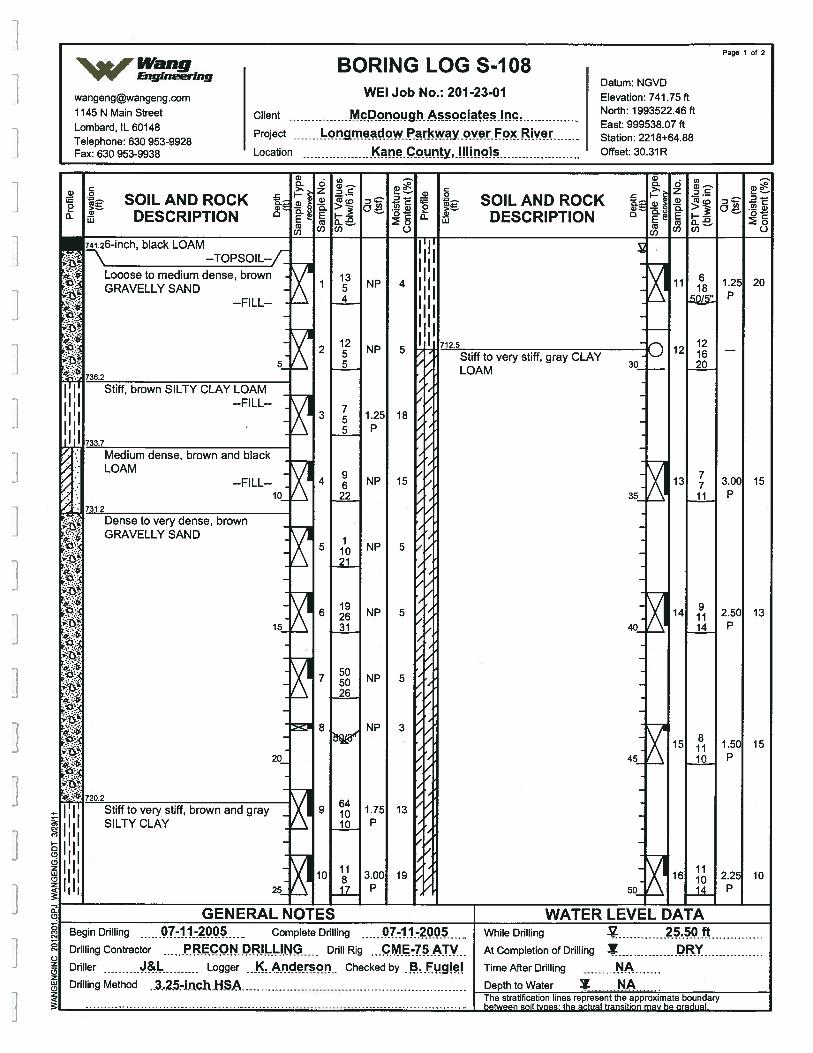
SOIL AND ROCKDESCRIPTION
GENERAL NOTESBegin Drilling 01-2005 Complete Drilling 07-11-2 -
Drilling Contractor RECON DRILLING Drill Rig ...cME-Z5ATVDriller J&L Logger K. Anderson Checked by B. Fugie!Drilling Method .3,25-inch HSA
SOIL AND ROCKDESCRIPTION
WATER LEVEL DATAWhile Drilling 25..50.ftAt Completion of Drilling Y DRYTime After Drilling NADepth to Water I NA
represent the approximate boundary
Page 1 of 2
Wang BORING LOG S-108VV Engr-rng
Datum NGVDwangengwangeng.com WEI Job No.: 201-23-01 Elevation: 741.75 ft
1145 N Main Street Client McPonough Assoc ates Inc - North: 1993522.46 ft
T:3O9539928Project ?.Y.IFP Ri’1
- Station: 221 8+648
Fax: 630 953-9938 Location c.cunty,.,!I!inois Offset: 30.31R
Looose to medium dense, brownGRAVELLY SAND
GRAVELLY
SILTY CLAY
]
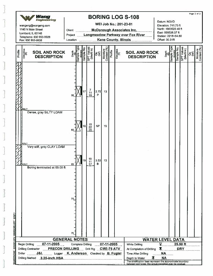
17 2.7518 P
page 2 of 2
Wang BORING LOG S-108vw’ Eng,neerrng
Datum NGVDwangengwangeng.com WEI Job No.: 201-23-01 Elevation: 741 .75ft
1145 N Main Street Client Mcppnpug.hAssociates.Inc North: 1993522.46 ft
L b d IL 60148 East: 999538.07 ft
T&ephone: 630 953-9928Project ngmeadow Parkway over F RIV Station: 221 8+64.88
Fax: 630 953-9938 Location cane.County,.N!inois Offset: 30.31R
5) 0).a-s . -
SOILANDROCK SOILANDROCKDESCRIPTION 0 & DESCRIPTION 0
( 0 (#2(1) 0
55
384.7
Dense, gray SILTY LOAM
6O
13
19
13
18 NP20
19
879.7
Very stiff, gray CLAY LOAM
676.7 65Boring terminated at 65.00 ft
101117
3-53B
70
75
1j
a,
a,I0(5(9zw(9z
aC, GENERAL NOTES WATER LEVEL DATA
Begin Drilling 07-11-200 - Complete Drilling 07-11-200 While Dñlling .50 ftDrilling Contractor PREcQN. PRI L.LI.NG Drill Rig CME.5 .ATV At Completion of Drilling DRYDriller
-Logger ...ncIeIS.Ofl. Checked by B. Fugicl , TimeAfterDrilling NA
Drilling Method ..3..2-.inchHSA Depth to Water AThe stratification lines represent the approximate boundary
between
soil Woes: the actual transition may be gradual.
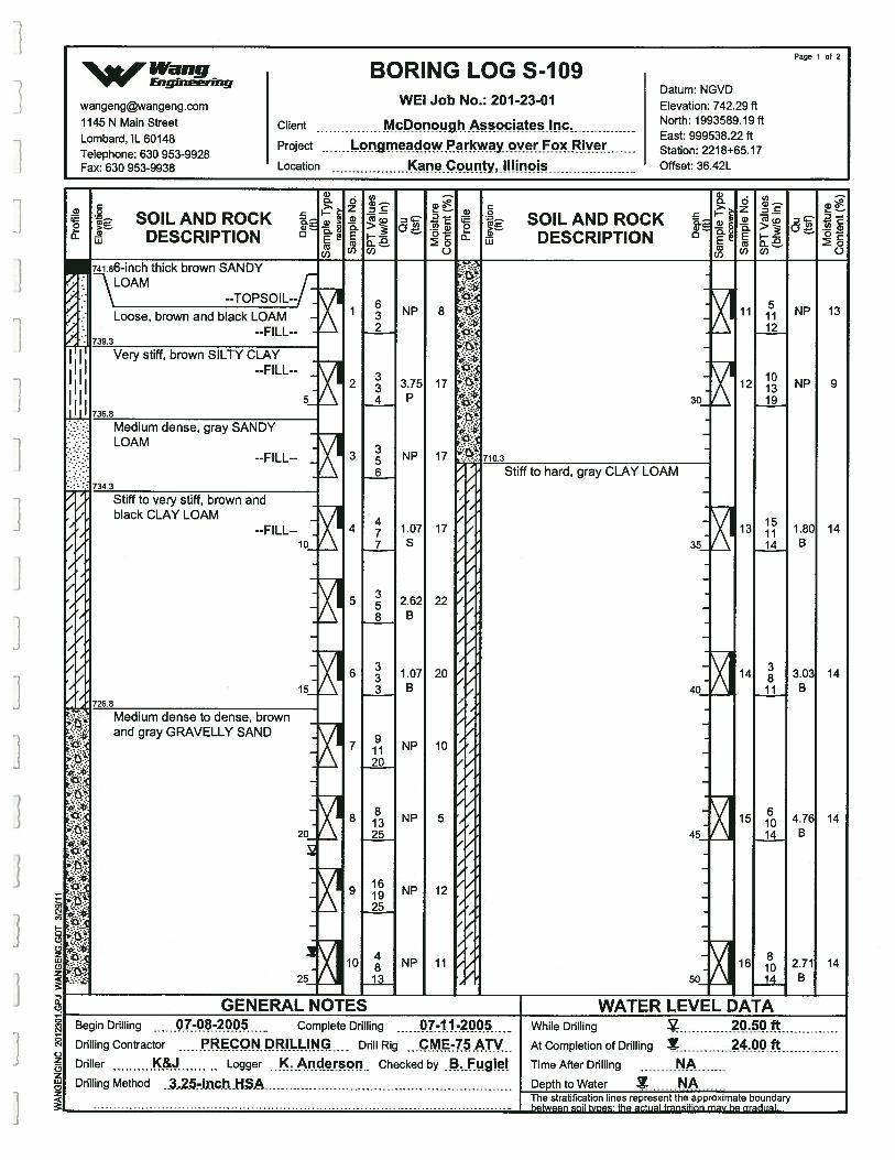
SOILAND ROCKt DESCRIPTION
SOIL AND ROCKDESCRIPTION
--TOPSOIL
Loose, brown and black LOAM--FILL--
Very stiff, brown SILTY CLAY--FILL--
and gray
GENERAL NOTESBegin Drilling 7-08-2 Complete Drilling Q71.1.-ZQ.ODrilling Contractor PRECON DRILLING Drill Rig ....M.E-75.ATV..Driller K8. Logger Checked by B. FugielDrilling Method
. .a.2.5-ijich .HSA
While Drilling 20.59.ftAt Completion of Drilling 24.00 ftTime After Drilling NADepth to Water
Page 1 of 2
Wang BORING LOG S-109‘VV 1,neerII7g
Datum NGVDwangengwangeng.com WEI Job No.: 201-23-01 Elevation: 742.29 ft1145 N Main Street Client McDonough Associates Inc North: 1993589.19 ft
L b d 1L60148 East:999538.22ft
Tephone: 630 953-9928Project gmeadowParkway.cwerF River Station: 2218+65.17
Fax: 630 953-9938 Location Kane unty,.Illlnpis Offset: 36.42L
.1
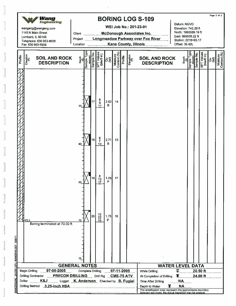
Page 2 of 244 Wang BORING LOG S-109Eng,neenng
Datum NGVDwangengwangeng.com WEI Job No.: 201-23-01 Elevation: 742.29 ft
1145 N Main Street Client MçPonpugjiAqciteslnc Noilh: 1993589.19 ft
Lombard IL 60148 East: 999538.22 ft
Telephone: 630 953-9928Project nmeadow yOVer Fox Rive Station: 2218+65.17
Fax: 630 953-9938 Location Dounty, Illinois Offset: 3642L
0) - Co - CO
;_
t SOILANDROCK SOILANDROCKDESCRIPTION 0 DESCRIPTION 0 .
(y 00) 0 ( 0
I
I
I
I
I
I
55
60
65
70
17 2.62ii B
18 2.7113 B
19 1.2517 P
20 1.75
18 P
14
13
17
16
Boring terminated at 70.00 ft
75
GENERAL NOTES WATER LEVEL DATABegin Drilling 07-08-200 Complete Drilling -11-2005 - While Drilling .OftDrilling Contractor PRECON DRILLING - Drill Rig CME-75 ATV At Completion of Drilling Y 24.00 ftDriller K& - Logger K. Anderson Checked by B. Fugiel Time After Drilling NADrilling Method .3.2.54ncji .HSA Depth to Water 1 NA
The stratification lines represent the approximate boundary
beeen
soil hoes: the actual transition may be gradual
‘%Wr Wang -
Engineering
APPENDIX B
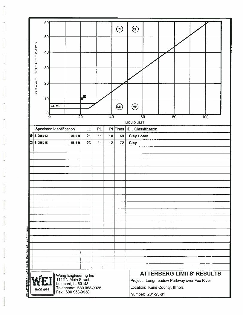
PLAS
ITV
NDEx
60
/5C
74C 7/
30__
/
2C
7
10 F’ 77./
CLML
()0 20 40 60 80 luO
LIQUID LIMIT
Specimen Identification LL PL P1 Fines IDH Classification
• S-095#12 28.5 ft 21 11 10 69 Clay Loam
Z S-096#18 58.5ft 23 11 12 72 Clay
Wang Engineerhg Inc - ATTERBERG LIMITS’ RESULTS1145 N Main Street Project: Longmeadow Parkway over Fox RiverLombard, IL 60148Telephone: 630 953-9928 Location: Kane County, IllinoisFax: 630 953-9938
Number: 201-23-01
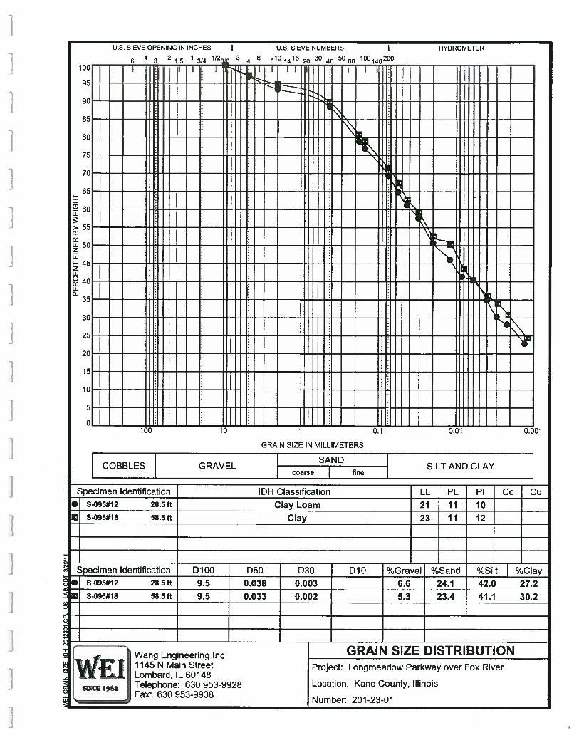
I—
0U-i
>-
UJzUI—zUI0UI
GRAIN SIZE IN MILLIMETERS
COBBLES GRAVELSAND
SILT AND CLAYcoarse fine
C,Specimen Identification IDH Classification LL PL P1 Cc Cu
• S-095#12 28.5 ft Clay Loam 21 11 10X S-096#18 58.5 ft Clay 23 11 12
Specimen Identification D100 D60 D30 D10 %Gravel %Sand %SiItJ/oClay.1 S-095#12 28.5 ft 9.5 0.038 0.003 6.6 24.1 42.0 27.2
S-096#18 58.5 ft 9.5 0.033 0.002 5.3 23.4 41.1 30.2
I GRAIN SIZE DISTRIBUTION
WiWang Engineering Inc
, 1145 N Main Street Project: Longmeadow Parkway over Fox River
SCE Telephone: 630 953-9928 Location: Kane County, Illinois: Lombard, 1L60148
Fax: 630 953-9938I Number: 201-23-01
U.S. SIEVE OPENING IN INCHES
6 3 2 L5 1 1/2Ii U.S. SIEVE NUMBERS
3 6 810 1416 20 30 40 5060 100140200
HYDROMETER
1009 T:T TTTI
-——-——— Ic——85 -—:—
8C : ——:— :
75——— :
7C .--——---—
65 ——— ——:— ——— . ———
UI UI
:HH H HHHdH H HHHH100 10 0. 0.01 0.001
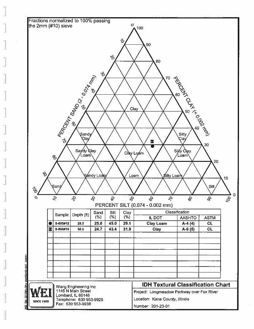
Fractions normalized to 100% passingthe 2mm (#10) sieve 100
90
80
I 70-O
60
Clay501:
0
40
and SiltyIa Ia
0 I30
Sa dy lay Cl Lo m Si yLoam Loam
20
ndy Lo Loam ilty Loa10
an Silt
0
PERCENT SILT (0.074 - 0.002 mm)
Sand Silt Clay ClassificationSample Depth (ft) (%) (%) (%) IL DOT AASHTO ASTM
• S-095#12 28.5 25.8 45.0 29.1 Clay Loam A-4 (4) CL
X S-096#18 58.5 24.7 43.4 31.9 Clay A-6 (5) CL
Wang Engineering Inc IDH Textural Classification Chartll45NMain StreetLombard, IL 60148
Project: Longmeadow Parkway over Fox River
SINCE Telephone: 630 953-9928 Location: Kane County, IllinoisFax: 630 953-9938
Number: 201-23-01
0
C
LI
‘WrWang -
Engineering
APPENDIX C
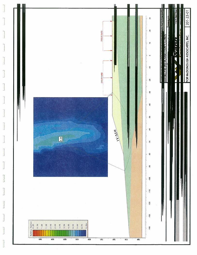
c_-
-;,
(.
_
--
-L
—J‘
L-J
I’
Safe
tyF
acto
r0
.00
0.5
0
1.0
0
2.0
0
2.5
0
3.0
0
3.5
0
4.0
0
4.5
0
5.0
0
5.5
0
—6.0
0+
t a-
1;
25
000
Ib/5
2
r/ /
2500
0b1
52
I —
-140
-130
-120
-110
-100
-90
-80
-70
-60
-50
-45
-30
-20
-10
1020
30
IFOR
McD
ON
OU
GH
ASS
OD
ATE
S,IN
C.201-2
3-0
1
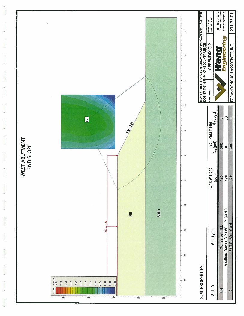
LJ
-‘
‘I
_
Safe
tyF
acto
r0
.00
0.5
0
1.0
0
1.5
0
2.0
0
2S
f
3.0
0
3.5
0
4.0
0
4.5
0
5.0
0
5.5
0
6.0
0*
WES
TA
BU
TMEN
TEN
DSL
OPE
-25
-20
-15
.10
-50
5IC
IS25
SOIL
PRO
PER
TIES
.U
nit
Wei
ght
Soil
Par
amet
erSo
ilID
Soil
Typ
e(p
cf)
Cu(p
sf)
P(d
eg.)
Fill
Coh
esiv
eFI
LL12
510
000
1M
ediu
mD
ense
GR
AV
EL
LY
SAN
D12
00
-33
2St
iffC
LAY
LOA
M12
0-
-13
000
SLO
PEST
ABI
LITY
AN
ALY
SIS:
LON
GM
EAD
OW
PARK
WA
YO
VER
FOX
RIV
ERlO
OT
NO
.P-
91-3
93-9
4.K
AN
EC
OU
NTY
,IL
LIN
OIS
SCA
LE:G
RAPH
ICA
PPEN
DIX
C—2
I DRA
WN
BY.A
.A.K
.
CHEC
KRD
BY:M
AIl
.
1145
N.
Mai
nS
tree
tII
’aii
gL
om
bar
d,
IL6
o1
4u
Eng
ineeri
ng
ww
w.w
ange
ngco
rn
250.
001b
I1I2 1
Fill
N
Soil
1
‘:
-
25
FOR
McD
ON
OU
GH
ASS
OCI
ATE
S,IN
C.201-2
3-0
1
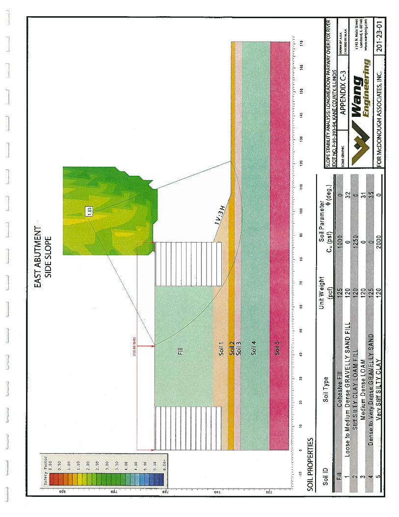
_
LL
JL
JL
..
_
I-
jI
II
-10
010
2030
4350
6070
8090
100
110
120
030
140
150
160
170
SOIL
PRO
PER
TIE
S
Fill
Coh
esiv
eFi
ll1
Loo
seto
Med
ium
Den
seG
RA
VE
LL
YSA
ND
FILL
2St
iffSI
LTY
CLA
YLO
AM
FILL
Med
ium
Den
seLO
AM
Den
seto
Ver
yD
ense
GR
AV
EL
LY
SAN
DV
ery
Stiff
SILT
YC
LAY
125
00
120
012
012
5012
00.,..,,
3112
5.
0.......
3512
020
000
Safe
tyF
acto
r—
0.0
0
EAST
AB
UT
ME
NT
SID
ESL
OPE
6 a F. a ,-
—-------------
L25
0,00
Ib!5
2
__
__
__
__
z.
____
SoiI
4
Soil5’
“lU
nit
Wei
ght
Soil
Par
amet
erSo
ilID
Soil
Typ
e(p
cf)
C(p
sf)
4)(d
eg.)
3 4 5
r-
1T—
rz
32 0
SLO
PEST
ABI
LITY
AN
ALY
SIS:
LON
GM
EAD
OW
PARK
WA
YO
VER
FOX
RIV
ERD
OT
NO
.P-
91-3
93-9
4.K
AN
EC
OLJ
NTV
IIIinic
I OR
KW
NK’
FkA
K.OC
ALK.
GR
APH
ICA
PPE
ND
IXC—
3IC
HEC
KED
BYM
AK
.
1145
N.M
ain
Str
eet
Lom
bard
.IL
6014
8
Eng
ineeri
nq
ww
w.w
ange
ng.c
om
201-2
3-0
1FO
RM
cDO
NO
UG
HA
SSO
CIA
TES,
INC.


