STRUCTURE AND BREAKUP PROPERTIES OF … AND BREAKUP PROPERTIES OF SPRAYS ... and that atomization...
29
~ Pergamon Int. J. Multiphase Flow Vol. 21, Suppl. pp. 99-127, 1995 Copyright © I995 Elsevier Science Ltd 0301-9322(95)00059-3 Printed in Great Britain. All rights reserved 0301-9322/95 $29.00+ 0.00 STRUCTURE AND BREAKUP PROPERTIES OF SPRAYS G. M. FAETH, L.-P. HSIANG and P.-K. WU Department of Aerospace Engineering, 3000 FXB Building, The Universityof Michigan, Ann Arbor, MI 48109-2118, U.S.A. (Received 25 July 1995) Abstraet--Multiphase flow phenomena relevant to spray combustion are reviewed, emphasizing the structure of the near-injector dense-spray region and the properties of secondary and primary breakup. Existing measurements of dense-spray structure are limited to round pressure-atomized sprays in still gases and show that the dispersed flow region is surprisingly dilute, that separated flow effects are significant because the flow is dilute and developing, and that atomization involves primary breakup at the liquid surface followed by secondary breakup, while effects of collisions are small. Available information about secondary breakup emphasizes breakup due to shock wave disturbances at large liquid/gas density ratios and shows that secondary breakup is a dominant feature of dense sprays that must be resolved as a function of time so that secondary breakup can be properly treated as a rate process. Finaily, available information about primary breakup has been dominated by effects of disturbances in the injector passage; therefore, while some understanding of turbulent primary breakup has been achieved, more information about aerodynamic primary breakup is needed to address practical spray combustion processes. Key words: atomization, dispersed flow, injection, primary breakup, secondary breakup, sprays 1. INTRODUCTION There have been numerous studies of non-combusting and combusting sprays, emphasizing the dilute region far from the injector exit, where observations and modeling are relatively tractable due to small liquid volume fractions. As a result, many features of dilute sprays are understood reasonably well, see the reviews due to Giffen & Muraszew (1953), Levich (1962), Harrje & Reardon (1972), Clift et al. (1978), Lefebrve (1980, 1983, 1989), Law (1982), Sirignano (1983), Wierzba & Takayama (1988), Annamalai & Ryan (1992), Faeth (1977, 1983, 1987, 1990) and references cited therein. Thus, attention now is being directed to the less accessible dense-spray region near the injector exit, in order to determine how injector design properties and the spray environment influence flow properties entering the dilute-spray region. Thus, the objective of this paper is to briefly review these efforts and to identify areas where additional research is needed. Three aspects of multiphase flow relevant to spray combustion are reviewed as follows: (1) the structure of the near-injector dense-spray region, in order to help define the environment of various dense spray processes; (2) the properties of secondary breakup, which often is the rate controlling process of dense sprays in much the same way that drop vaporization often is the rate controlling process of dilute sprays; and (3) the properties of primary breakup, which define initial conditions for dense sprays and most directly connect injector design properties (hardware) and spray properties. Due to space limitations, however, present considerations will be limited to processes directly relevant to non-evaporating round pressure-atomized sprays in still gases. Ignoring evaporation is reasonable because the dense-spray region of combusting sprays generally involves cool portions of the flow where rates of heat and mass transfer are modest. Additionally jet flows in still gases are a simple classical flow configuration that exhibit most features of dense-sprays while only requiring a few defining parameters. Information about other spray processes and injection configurations can be found in the review articles cited earlier, and references cited therein. In the following, dense-spray structure, secondary breakup and primary breakup will be considered in turn. The description of each topic is sufficiently complete so that it can be read independently, if desired. IJMF 21/7~ 99
Transcript of STRUCTURE AND BREAKUP PROPERTIES OF … AND BREAKUP PROPERTIES OF SPRAYS ... and that atomization...

~ Pergamon Int. J. Multiphase Flow Vol. 21, Suppl. pp. 99-127, 1995 Copyright © I995 Elsevier Science Ltd
0301-9322(95)00059-3 Printed in Great Britain. All rights reserved 0301-9322/95 $29.00 + 0.00
S T R U C T U R E A N D B R E A K U P P R O P E R T I E S O F S P R A Y S
G. M. FAETH, L.-P. HSIANG and P.-K. WU Department of Aerospace Engineering, 3000 FXB Building, The University of Michigan, Ann Arbor,
MI 48109-2118, U.S.A.
(Received 25 July 1995)
Abstraet--Multiphase flow phenomena relevant to spray combustion are reviewed, emphasizing the structure of the near-injector dense-spray region and the properties of secondary and primary breakup. Existing measurements of dense-spray structure are limited to round pressure-atomized sprays in still gases and show that the dispersed flow region is surprisingly dilute, that separated flow effects are significant because the flow is dilute and developing, and that atomization involves primary breakup at the liquid surface followed by secondary breakup, while effects of collisions are small. Available information about secondary breakup emphasizes breakup due to shock wave disturbances at large liquid/gas density ratios and shows that secondary breakup is a dominant feature of dense sprays that must be resolved as a function of time so that secondary breakup can be properly treated as a rate process. Finaily, available information about primary breakup has been dominated by effects of disturbances in the injector passage; therefore, while some understanding of turbulent primary breakup has been achieved, more information about aerodynamic primary breakup is needed to address practical spray combustion processes.
Key words: atomization, dispersed flow, injection, primary breakup, secondary breakup, sprays
1. INTRODUCTION
There have been numerous studies of non-combusting and combusting sprays, emphasizing the dilute region far from the injector exit, where observations and modeling are relatively tractable due to small liquid volume fractions. As a result, many features of dilute sprays are understood reasonably well, see the reviews due to Giffen & Muraszew (1953), Levich (1962), Harrje & Reardon (1972), Clift et al. (1978), Lefebrve (1980, 1983, 1989), Law (1982), Sirignano (1983), Wierzba & Takayama (1988), Annamalai & Ryan (1992), Faeth (1977, 1983, 1987, 1990) and references cited therein. Thus, attention now is being directed to the less accessible dense-spray region near the injector exit, in order to determine how injector design properties and the spray environment influence flow properties entering the dilute-spray region. Thus, the objective of this paper is to briefly review these efforts and to identify areas where additional research is needed.
Three aspects of multiphase flow relevant to spray combustion are reviewed as follows: (1) the structure of the near-injector dense-spray region, in order to help define the environment of various dense spray processes; (2) the properties of secondary breakup, which often is the rate controlling process of dense sprays in much the same way that drop vaporization often is the rate controlling process of dilute sprays; and (3) the properties of primary breakup, which define initial conditions for dense sprays and most directly connect injector design properties (hardware) and spray properties. Due to space limitations, however, present considerations will be limited to processes directly relevant to non-evaporating round pressure-atomized sprays in still gases. Ignoring evaporation is reasonable because the dense-spray region of combusting sprays generally involves cool portions of the flow where rates of heat and mass transfer are modest. Additionally jet flows in still gases are a simple classical flow configuration that exhibit most features of dense-sprays while only requiring a few defining parameters. Information about other spray processes and injection configurations can be found in the review articles cited earlier, and references cited therein.
In the following, dense-spray structure, secondary breakup and primary breakup will be considered in turn. The description of each topic is sufficiently complete so that it can be read independently, if desired.
IJMF 21/7~ 99

100 G.M. FAETH et aL
2. DENSE SPRAY STRUCTURE
2.1. Introduction
Round pressure-atomized sprays in a still gas are a classical spray configuration that will be used to illustrate the environment of dense sprays, based on results described by Clift et al. (1978), Faeth (1987, 1990), Ruff & Faeth (1995), Ruff et al. (1989, 1991, 1992), Tseng et al. (1992a, b, 1995) and Wu et al. (1995b). Early studies of this spray configuration emphasized spray breakup regimes, including conditions required for the important atomization breakup regime where drop formation begins right at the jet exit, see Reitz & Bracco (1982), Miesse (1955), Ranz (1958) and Phinney (1973). Subsequent work concentrated on visualization of the near-injector region of the flow and definition of the properties of the liquid core, which is similar to the potential core of a single-phase jet, see Phinney (1973), Hoyt & Taylor (1977a, b), Hiroyasu et al. (1982) and Chehroudi et al. (1985). More recently, Wu et al. (1983, 1984) have studied the properties of the dilute spray region near the outer edge of the spray. Emphasis in the following, however, will be on the dense spray region, based on the measurements of Ruff et al. (1989, 1991, 1992) and Tseng et al. (1992a, b). For these conditions, flow regimes and flow structure will be considered, in turn.
2.2. Flow regimes
The atomization breakup regime of round pressure-atomized sprays is most important because it provides the fine atomization needed for rapid mixing of liquid and gas phases during practical combustion processes. A sketch of the flow within the near-injector region for this breakup regime is illustrated in figure 1. There are two main multiphase flow regions within dense sprays; namely, the liquid core and the dispersed flow region beyond the surface of the liquid core. As noted earlier, the liquid core is similar to the potential core of a single phase jet, although it is generally much longer. For example, Chehroudi et al. (1985) find the following expression for the length, Lo, of the liquid core:
Lc/d = Cc(pL:/pG) t/2 [1]
where d is the injector diameter, PL and Pc are the liquid and gas densities, respectively, and Cc is an empirical constant in the range 7-16. This implies Lc/d in the range 200-500 for typical sprays at atmospheric pressure, with this ratio generally being inversely proportional to the square root of pressure. Thus, liquid cores are a very prominent feature of round pressure-atomized sprays.
The dispersed flow region beyond the liquid surface involves a developing multiphase mixing layer in the region where the liquid core is present, followed by a multiphase jet that evolves into a dilute round spray flow. The multiphase mixing layer begins close to the jet exit within the atomization breakup regime. Primary breakup occurs due to the formation of ligaments and other irregular liquid elements along the surface of the liquid core. Thus, rates of primary breakup tend to control the length of the liquid core. The dense spray region generally is associated with the
+ DILUTE DENSE SPRAY | SPRAY MULTIPHASE ~ _ _ ~ _ _ _ - -- ~ ~ |
. "~ MIXING LAYER ". o
LIQUIFLoW
. . . . _ o . . : o --"~k°"~---~'-,~'~ ~ o . v 2.. o
/ ,NI LIQUID CORE r ~ " "
INJECTOR DISPERSED FLOW Figure 1. Sketch of the near-injector region of a pressure-atomized spray in the atomization breakup
regime.
STRUCTURE AND BREAKUP PROPERTIES OF SPRAYS 101
3
1.2
1.0 i
7 1.0
7 1.0 ~"'
1.0 i,,,
0.8 --
0.6
L 0.4
0.2
0 0
' ' ' I ' ' " 1 '
I a r m
2 a t m O ~
4 arm ~ ~(~
8 arm
5 I0 x/d
\
\
FULLY-DEVELOPED FLOW 0 DATA
T H E O R Y
, , ~ , , , ,9 50 I00
Figure 2. Time-averaged liquid volume fractions along the axis of round pressure-atomized water sprays in still air at various pressures for atomization breakup with fully-developed turbulent pipe flow at the
jet exit. From Tseng e t al. (1992a).
presence of the liquid core although this definition is not very precise, e.g. the edge of this region is a dilute spray while the region just downstream of the liquid core has large liquid volume fractions typical of a dense spray condition. The outcome of primary breakup frequently is irregular drops or ligaments while most liquid elements resulting from primary breakup are unstable to secondary breakup: these are features that are typical of dense sprays. Finally, the properties of dense sprays, or even the existence of the dense spray region, are strongly dependent upon liquid flow properties (disturbance levels, vorticity properties, turbulence levels, etc.) at the jet exit, as will be discussed later.
2.3. Flow structure
Ruff et al. (1989, 1991, 1992) and Tseng et al. (1992a, b) observe significant effects of the degree of development of turbulence at the jet exit on dense spray properties. Thus, in order to fix ideas, subsequent information about dense spray properties will be limited to conditions where there is fully-developed turbulent pipe flow at the jet exit. Measured and predicted time-averaged liquid volume fractions along the axis of the dense spray region, ~Lc, for water injected into air at various pressures, from Tseng et al. (1992a), are illustrated in figure 2 as a function of the distance from the jet exit, x. The measurements were completed by Ruff et al. (1989) and Tseng et al. (1992a) by deconvoluting gamma-ray absorption determinations for cord-like paths through the flow; notably, the two sets of measurements are in excellent agreement in the region where they overlap. The predictions are based on a Favre-averaged turbulence model under the locally-homogeneous flow (LHF) approximation, where relative velocities between the phases are assumed to be small in comparison to mean flow velocities, see Ruff et al. (1989), for a complete description of this model.
The region near the jet exit ( x / d < 3-8) illustrated in figure 2, exhibits mean liquid volume fractions near unity, followed by a rapid reduction of the liquid volume fraction. The initial reduction of liquid volume fractions occurs at progressively smaller values of x / d as the pressure increases, indicating faster mixing rates at higher ambient gas densities, analogous to effects of flow density ratio for single-phase turbulent jets, see Ricou & Spalding (1961). There is good agreement between measurements and predictions; nevertheless, these conditions represent relatively low levels of mixing as will be discussed subsequently. For such conditions, LHF predictions generally are reasonably good, because separated flow effects due to relative velocity differences between the gas

102 G, M. FAETH et al.
and the liquid are not very significant when the flow is mainly liquid. Finally, although the variation of liquid volume fraction suggests a relatively short liquid core, this is not the case when viewed in terms of mixture fraction. Results to be considered next will show that Favre-averaged mixture fractions are near unity for all the conditions illustrated in figure 2, so that even low levels of flapping of the liquid core can explain the liquid volume fraction reductions.
Ricou & Spalding (1961) have shown that properties along the axis of single-phase variable-den- sity jets should scale in terms of a normalized density-weighted streamwise distance, (pG/pL)l/2x/d, while Chehroudi et al. (1985) recommend similar scaling based on their measurements of liquid core lengths as discussed in connection with [1]. Thus, predicted and measured Favre-averaged mixture fractions along the axis,re, where the subscript c denotes a property along the axis (mixture fraction simply corresponds to the mass fraction of water for these conditions) are plotted as a function of this variable in figure 3, for the same conditions as figure 2. When plotted in this manner, both measurements and predictions exhibit little effect of ambient pressure and also show that liquid volume fractions generally are near unity in this region, as noted earlier. Nevertheless, the LHF predictions vastly overestimate the subsequent rate of reduction of mass fractions with increasing streamwise distance, and thus the mixing rates. The corresponding slower rates of mixing along the axis than LHF predictions suggest significant effects of separated flow just downstream of the end of the liquid core. This behavior is plausible, because breakup of the end of the liquid core yields large drops that maintain significant relative velocities due to their large inertia. Thus, separated flow effects are an important feature of dense sprays. Another result illustrated in figure 3 is the effect of jet exit flow conditions on spray mixing rates as evidenced by the slower rate of development of the non-turbulent slug flow in comparison to the fully-developed turbulent pipe flow at the jet exit (most evident at the farthest downstream position).
Predicted and measured radial profiles of mean liquid volume fractions at atmospheric pressure are plotted as a function of radial distance, r, in figure 4, for the same conditions as figures 2 and 3. The independent measurements of Ruff et al. (1989) and Tseng et aL (1992a) agree within experimental uncertainties, except for x / d = 100 where the greater confinement of the flow studied by Tseng et al. (1992a) might be a factor. The measurements show a progressive increase of flow width with increasing distance from the jet exit. The comparison between LHF predictions and
1.0
0.8
0.6
0.4
1.0"
0.8
0.6
0.4
FULLY-DEVELOPED FLOW " ~
1
, P R . E N T 2 PRESENT
V 4 PRESENT 0 8 PRESENT • I RUFF etol
THEORY I-8 PRESENT
0.2
o.o I I ! I I 0 2 4 6 8 I0 12
I / 2 (Pe IPt.) xlcl
Figure 3. Favre-averaged mixture fractions along the axis of round pressure-atomized water sprays in still air at various pressures for atomization breakup with fully-developed turbulent pipe flow at the jet exit.
From Tseng et al. (1992a).

STRUCTURE AND BREAKUP PROPERTIES OF SPRAYS 103
measurements is reasonably good, except at larger values of x / d : Ruff et al. (1989) show that this difficulty is due to effects of separated flow as the flow becomes more dilute.
Tseng et al. (1992b) directly assess effects of separated flow in the dense spray region of round pressure-atomized sprays using double-pulsed holography to measure drop size and velocity distributions, in the mixing layer, as well as the position of the surface of the liquid core. These results allowed the determination of Favre-averaged flow velocities, for direct comparison with LHF predictions, assuming that the velocities of 5 [tm diameter drops were representative of gas velocities. The resulting measured and predicted streamwise mean phase velocities (Favre-averaged and gas phase velocities) at a typical streamwise location ( x / d = 25) are plotted in figure 5 for ambient pressures of 1, 2 and 4 atm. The velocities on this plot are normalized by the injector exit velocity, Uo. The range of measured positions of the liquid surface are also shown on the plots for reference purposes. In general, the measured Favre-averaged velocity is significantly greater than the gas velocity, although the differences between the two decrease as the ambient pressure increases. In addition, the LHF predictions are not very satisfactory, which is expected due to the presence of significant effects of separated flow.
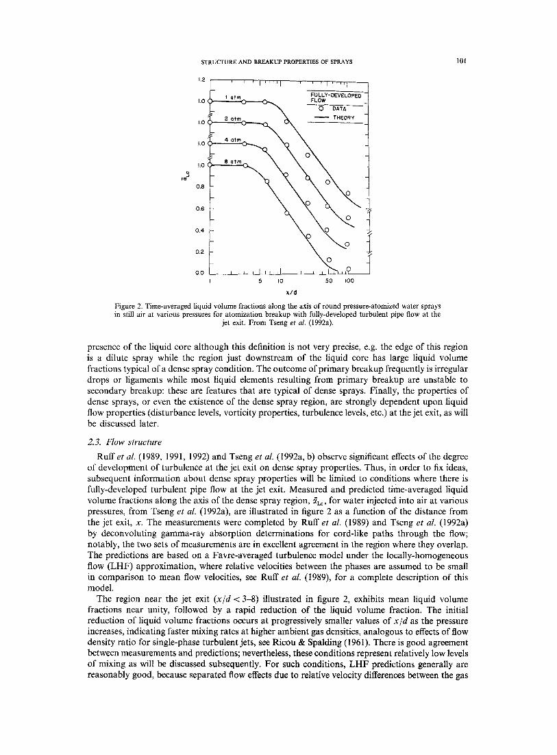
Additional insight concerning separated-flow effects in dense sprays can be obtained from the structure properties plotted in figure 6. The results in this figure include the ellipticity of the drops, ep, the Sauter mean diameter of the spray, SMD, and drop velocities, Up for various drop diameters, dp. These results are for the same conditions as figure 5, with both data and predictions obtained from Ruff et al. (1992), but they are typical of findings at other conditions within the dense spray region. The region near the liquid surface consists of large, irregular, ligament-like elements (large ev and SMD), even though this spray had good atomization properties, while the dilute spray region near the edge of the flow involves smaller round drops. This provides direct evidence of significant levels of secondary breakup in the dense spray region near the liquid surface. In addition, the dispersed flow region, exterior to the liquid core, was surprisingly dilute (with mean liquid volume fractions less than 0.1%), see Ruff et al. (1992) and Tseng et al. (1992b); therefore, the large mean liquid volume fractions observed in some portions of the dense spray region are mainly due to the
3
.J Io
L o 9c ,~ , , , , , , ,
o5 L x,.o~ , , , ~ . \ O o . . _ x/d=~oo -f
, 'o._ -1 1.0 • 12.5
o.5~- , ~X,
| L - ~ L O P E D - "
0.5 ~ - , I m THEORY "
o 2
2r/d
Figure 4. Radial profiles of time-averaged liquid volume fractions along the axis of round pressure-atomized water sprays in still air at atmospheric pressure for atomization breakup with fully-developed turbulent pipe flow at the jet
exit. From Tseng et al. (1992a).
1.0
0.5
0.0 1.0'
~ . = lli::ill FULLY-OEVELOPED- Ii:iii:~ FLOW
~] o ~AVRE ~V~RA~-~ I:::~: :~. A GAS*PHASE(5.um) / ! i i l \ =,
?}?.{;iI j" ~ E 4 arm
: i::iiill ~ QUIO SURFACE
x. . o o 2o*m 0.0
1 . 0 ; i ~
0.5
0.0 0.00 O, I0
r /x
c¢ ~ J otm J I
0.20
Figure 5. Radial profiles of mean phase velocities for round pressure-atomized water sprays in still air at various press- ures for atomization breakup with fully-developed turbulent
pipe flow at the jet exit. From Tseng et al. (1992b).
104 G.M. FAETH et al.
Q,
1 5 0 0
E I 0 0 0 - , . j
: i o3
5 0 0 -
0 , /
6 0 '
= 4 0 :
2 0
0 0
I I ) I
0 0
0
0 0
0
I
FULLY- DEVELOPED FLOW
x / d • 2 5
0 0
I I
SURFACE (TYP)
o o
Up dp ( p m ) -
_ 0 I 0 "
• 3 0
i O 0 e__ 300
- • THEORY -
- • • ~ -
; o I 1',,. I
0.10 0 . 2 0
r l x
Figure 6. Radial profiles of dispersed-phase properties for round pressure-atomized water sprays in still air at atmospheric pressure for atomization breakup with fully-developed turbulent pipe flow at the jet
exit. Data from Ruff et al. (1992).
presence of the liquid core. The low liquid volume fractions within the dispersed flow region imply that collisions between liquid elements are improbable, see Faeth (1977, 1983, 1987). Thus, these findings support the conventional picture of atomization within dense sprays, as discussed by Giffen & Muraszew (1953), which involves primary breakup into ligaments and large drops at the liquid surface followed by secondary breakup into smaller round drops, with negligible effects of collisions.
A useful experimental finding of the studies of Ruff et al. (1992) and Tseng et aL (1992b) was that drop size distributions throughout the dense spray region are well correlated by the universal root-normal distribution with MMD/SMD = 1.2 due to Simmons (1977), where MMD is the mass median drop diameter of the spray. See Belz (1973) for a discussion of the properties of this distribution function. Then, since this distribution only has two parameters, the entire size distribution can be represented by the SMD alone. Another observation was that the drop sizes after primary breakup, as well as mixing rates throughout the flow which was noted earlier, were

STRUCTURE AND BREAKUP PROPERTIES OF SPRAYS 105
very dependent upon flow conditions at the injector exit--a finding that parallels the well known importance of jet exit conditions on the development region of single-phase turbulent jets.
The distributions of drop velocities illustrated in figure 6 show that they vary considerably with drop diameter at each point in the flow, providing direct evidence of significant separated flow effects in dense sprays. Near the liquid core, the largest drops have velocities comparable to mean liquid injection velocities, however, velocities decrease with both decreasing drop size and increasing radial distance. A surprising feature of these observations is that gas velocities (which approximate the velocities of the smallest drops) are low and are nearly constant across the width of the dispersed flow region. This implies relatively ineffective momentum exchange between the phases because the large drops contain most of the momentum and they respond slowly to drag forces due to their relatively large inertia. Finally, consistent with observations in connection with figures 2-5, the LHF predictions illustrated in figure 6 are poor because separated flow effects are important within most of the dense spray region.
2.4. Conclusions
Based on the study of the structure and mixing properties of dense sprays found near the injector for round pressure-atomized sprays in still gases, the following major conclusions are obtained:
(1) The large liquid volume fractions observed in dense sprays generally are due to the presence of the liquid core; in contrast, liquid volume fractions in the dispersed flow region beyond the liquid surface are small, less than 0.1%, so that the flow in this region corresponds to a dilute spray but with added complications due to the presence of irregular liquid elements and secondary breakup.
(2) Measurements generally support the traditional view of atomization expressed by Giffen & Muraszew (1953); namely, primary breakup at the liquid surface is followed by secondary breakup in a dilute spray environment where effects of drop collisions are negligible (except for spray conditions that strive for significant effects of collisions to enhance breakup rates, such as impinging injectors).
(3) Rates of mixing, drop properties and flow structure within dense sprays are strongly dependent on the degree of flow development and turbulence levels at the jet exit, and on the liquid/gas density ratio, somewhat analogous to the effect of these properties on the structure of the flow development region of single-phase jets.
(4) Effects of separated flow are important within dense sprays, with significant differences between the velocities of large drops and the gas due to the poor response properties of large drops. Thus, LHF predictions of the structure of dense sprays are not very effective, except at the highest liquid volume fractions where the momentum of the gas and small drops is negligible in any event.
(5) Drop size distributions after primary breakup, as well as after secondary breakup and on approach to the dilute spray region, all satisfied the universal root-normal drop size distribution with MMD/SMD = 1.2 due to Simmons (1977) at each point in dense sprays; therefore, the entire drop-size distribution can be characterized by a single moment, e.g. the SMD.
3. SECONDARY BREAKUP
3.1. Introduction
Based on the previous considerations of the structure of the dense spray region for round pressure-atomized sprays, secondary breakup clearly is an important process of dense sprays, through its effect on drop size distributions as the dilute spray region is approached. In particular, primary breakup at the surface of the liquid core yields drops that are intrinsically unstable to secondary breakup. In addition, high-pressure combustion for typical power and propulsion systems involves conditions where the surface tension of drops becomes small, because the liquid surface approaches the thermodynamic critical point; naturally, such conditions suggest potential for significant effects of drop deformation and secondary breakup. Prompted by these observations, current understanding of secondary breakup will be discussed in the following.

106 G.M. FAETH etal.
Giffen & Muraszew (1953), Levich (1962), Harrje & Reardon (1972), Clift et al. (1978), Wierzba & Takayama (1988), Hinze (1955) and Krzeczkowski (1980) have reviewed early work on secondary breakup; therefore, the following discussion will emphasize more recent studies. Of particular interest are the studies of Hsiang & Faeth (1992, 1993, 1995) and Hsiang et al. (1995) which have considered breakup regimes, breakup dynamics and the outcomes of breakup. In general, past work has been limited to two kinds of well defined disturbances that cause deformation and breakup of drops: shock wave disturbances that provide step changes in the ambient environment of a drop typical of a drop at the end of primary breakup; and steady disturbances typical of freely-falling drops in rainstorms or in spray drying processes. Effects of shock wave disturbances have received the most attention and approximate the secondary breakup environment of dense sprays; therefore, these disturbances will be emphasized in the following. Deformation and breakup regimes, breakup dynamics and breakup outcomes will be considered, in turn.
3.2. Deformation and breakup regimes
Numerous studies have considered the definitions and conditions for the onset of various deformation and breakup regimes of drops subjected to shock wave disturbances. When effects of liquid viscosity are small, the breakup regime observed at the onset of breakup has been termed bag breakup: it involves deflection of the drop into a thin disk normal to the flow direction, followed by deformation of the center of the disk into a thin, balloon-like structure, both of which subsequently divide into drops, see Wierzba & Takayama (1988), Hinze (1955), Krzeczkowski (1980), Hanson et al. (1963), Gel'fand et al. (1974), Ranger & Nicholls (1969) and Reinecke & McKay (1969) and Reinecke & Waldman (1970) for photographs of all the breakup regimes discussed here. The shear breakup regime is observed at higher relative velocities: it involves deflection of the periphery of the disk in the downstream direction, rather than deflection of the center of the disk, and the stripping of drops from the periphery of the disk. The transition between the bag and shear breakup regimes is a complex mixture of the two bounding regimes which will be denoted the multimode breakup regime in the following. A complex breakup mechanism also has been observed at very large relative velocities, which has been called catastrophic breakup by Reinecke & McKay (1969) and Reinecke & Waldman (1970), nevertheless, this regime is not seen in typical dense sprays and will not be considered here.
Existing observations of secondary breakup have generally involved PL/P~ > 500 and Re > 100, where Re = podu /#a and Po is the molecular viscosity of the gas. For these conditions, Hinze (1955) shows that breakup regime transitions are functions of the initial Weber number of a drop, We = Pc do u 2/a, where o- is the drop surface tension and the subscript o denotes an initial condition, and the Ohnesorge number of a drop, Oh - - I, ZL/(pLdoff) 1/2, where #L is the molecular viscosity of the liquid, which are measures of the ratios of drag and liquid viscous forces to surface tension forces, respectively. The resulting deformation and breakup regime map based on available results from Hinze (1955), Krzeczkowski (1980), Hsiang & Faeth (1992,1993,1995), Hanson (1963), Lane (1951) and Loparev (1975) is illustrated in figure 7. The various breakup regimes identified by Hinze (1955), Krzeczkowski (1980) and Hsiang & Faeth (1992, 1995) are in excellent agreement in the regions where they overlap; in view of the subjective nature of identifying breakup regime transitions, this degree of agreement is quite satisfying. The transitions to the deformation regimes are important because they define conditions where drop drag departs significantly from that of a solid sphere; these regimes are defined by the ratio of the maximum (cross stream) dimension to the original drop diameter. The oscillatory deformation regime is defined by conditions where the drop oscillates with a weakly damped amplitude, see Hsiang & Faeth (1992) for discussion of this behavior.
All regime transitions illustrated in figure 7 are relatively independent of liquid viscous forces (or Oh) for Oh < 0.01. The order of the transitions with increasing We in this region from Hsiang & Faeth (1995) is as follows: 5% deformation, We = 0.6; 10% deformation, We = 1.0; 20% deformation, We--2.1; oscillatory deformation, We--3.0; bag breakup, We = 13; multimode breakup, We = 35; and shear breakup, We = 80. As noted earlier, the We at breakup regime transitions due to Hinze (1955) and Krzeczkowski (1980) are similar to these results. These findings suggest quite plausibly that significant levels of deformation and breakup occur when dynamic

STRUCTURE AND BREAKUP PROPERTIES OF SPRAYS 107
E t--
o
104
103
102
101
100
Liquid Liquid Source
o n -Heptane • Glycerol 92% (5 Hanson etal. (1963) o Water * Glycerol 97% & Hinze (1955) A Glycerol 21% • Glycerol 99.5% ~> Lane (1951) v Glycerol 63% ~ Mercury <1 Loparev (1975) 0 Glycerol 75% D. 200 fluid - - - Krzeczkowski (1980) • Glycerol 84% ~ Present
<1 ,
I I I I I 10 .4 10 -3
pL/PG = 580-1200 /
Shear breakup . , ~ 2/~ Y
v 0 o.~....--Q~- m" , , ~ / Deformation _ _ . . . . . ~ _-- / . / ~ Z > 20% / ~'/";'~//,Z Multimode breakup ~...~'/~ . ~
Bag breakup . ~ . . - ~
Oscil latory deformation f
,0° o<0o,or *ion 0° o F1 r,-- ~ ~ ~ Deformation < 5%
5% < ~
I ) I l l I I I r l i i i l l t i i l l I q l i t ~ r f l l 10-2 10-1 10 0 101 10 2 10 3
Ohnesorge number
Figure 7. Drop deformation and breakup regime map for shock-wave disturbances with liquid/gas density ratios greater than 500. From Hsiang & Faeth (1995).
forces (or drag forces) are comparable to the stabilizing forces of surface tension if effects of liquid viscosity are small.
Perhaps the most striking feature of figure 7 is that while the values of We required for particular regime transitions are relatively constant for Oh < 0.1, they progressively increase with increasing Oh for Oh > 1. In addition oscillatory deformation disappears at Oh ~ 0.3 and bag breakup disappears at Oh ~ 4. Hinze (1955) and Levich (1962) observed this tendency for the limited ranges of Oh where data were available at the time, and conjectured that breakup might not be observed for Oh > 1 to 2. However, the large Oh behavior observed in figure 7 does not suggest such a limitation; rather, there is an almost linear increase of We at the deformation and breakup transitions with increasing Oh.
Clearly, it is crucial to establish whether large values of Oh imply no deformation or breakup as suggested by Hinze (1955) and Levich (1962), or simply rather large values of We at the transitions, as suggested by the measurements illustrated in figure 7; therefore, Hsiang & Faeth (1995) undertook phenomenological analysis in an attempt to explain the effect of Oh on deformation and breakup regime transitions. Their approach was based on the observation that the main effect of liquid viscosity for shock wave disturbances was to reduce the rate of deformation of the drop. This behavior allows more time for drop velocities to relax toward the local ambient velocity at large Oh, tending to reduce the relative velocity, and thus the driving potential for drop deformation, at each stage of the deformation process. The motion of the drop was analyzed for these circumstances, assuming Oh >> 1 so that maximum deformation occurred at a multiple of the characteristic viscous time, ~, of Hinze (1948), defined as follows:
= ~ / ( p o u~o) [2]

108 G.M. FAETH et al.
This analysis yielded the following relationship between We and Oh for particular deformation or breakup transitions at large Oh:
We = (Wecr/4) (1 + 4 K'Weg]/2(pG/PLf/EOh ) [3]
In [3], Wecr is the local Weber number at the maximum deformation condition required for the transition of interest to occur, while K ' is an empirical factor. Values of Wecr and K' were fitted to [3] to yield the best fit predicted transitions at large Oh illustrated in figure 7: in view of the simplifications of the theory, the agreement between the predicted and measured regime transitions is seen to be reasonably good. Notably, [3] suggests that transition We ~ Oh at large Oh rather than an ultimate limit for particular transitions as suggested by Hinze (1955) and Levich (1962). This is a very important difference in behavior that has significant relevance for processes of high-pressure combustion, where Oh becomes large as drops approach their thermodynamic critical point (because their surface tension approaches zero while their viscosity remains finite). Another issue concerning [3] is the effect of liquid/gas density ratio, which suggests further increases in We at a given transition as PG/PL increases, a parameter variation that has not been explored thus far. Thus, the large Oh regime transition criteria of [3] clearly merit additional study, emphasizing the large Oh and PG/PL conditions relevant to high-pressure spray combustion processes.
3.3. Breakup dynamics
The discussion of deformation and breakup regime transitions highlights the importance of breakup times and already has introduced the characteristic breakup time, z, when liquid viscous forces are large in comparison to surface tension forces at large Oh, see [2]. Available measurements of drop breakup times from Engel (1958), Simpkins & Bales (1972), Ranger & Nicholls (1969) Reinecke & Waldman (1970) and Hsiang & Faeth (1992) are plotted as a function of We and Oh in figure 8. In this plot, the breakup times, tb, are normalized by the characteristic breakup time for shear breakup at low Oh, t*, defined by Ranger & Nicholls (1969) as follows:
t * = do (pL/PG )1/2//'/o [4]
Except for the results of Hsiang & Faeth (1992), which are grouped according to Oh, the measurements are for Oh < 0.1; therefore, the deformation and breakup regimes defined earlier for these conditions are marked on the plot for reference purposes.
102
101
100 --
10 -1 100
Source Source Correlation
o Ranger & Nicholls (1969) [] Simpkins & Bales (1972) z~ Engel (1958) v Reinecke & Waldman (1970)
• Reinecke & McKay (1969) • Present (Oh < 0.1) • Present (1.0 < Oh < 2.8) • Present (3.5 < Oh)
- - O h : 3 . 5 - - ' - - O h : 2 . 0 ~ O h : 0 . 0
A - - • - - " - -
u - - n - - n ~
• . . A . . . . . . .
A A 0 0
O 0 r-, 7 z w V
Non-osc. Bag Shear
Osc. def. Multimode
I I I I I 101 102 103 104 105
We Figure 8. Drop breakup times as a function of the Weber and Ohnesorge numbers for shock-wave
disturbances with liquid/gas density ratios greater than 500. From Hsiang & Faeth (1992).
I 10 6

STRUCTURE AND BREAKUP PROPERTIES OF SPRAYS 109
A remarkable feature of the breakup time results illustrated in figure 8 for Oh < 0.1 is that tb/t * varies very little even though We varies widely and several breakup regimes are involved. In fact, the correlation developed for shear breakup by Ranger & Nicholls (1969):
tb/t* = 5.0 [5]
provides a good representation of all the measurements illustrated in figure 8 for Oh < 0.1. At larger Oh, however, tb/t* increases due to effects of liquid viscosity retarding the rate of deformation as discussed earlier. In this region, an empirical correlation is defined by Hsiang & Faeth (1992) but this expression is only appropriate for Oh < 3.5. Surprisingly, no attempt has been made to apply the characteristic viscous time, ~, to correlate breakup times at large Oh: this should be done in order to both check the development of the large Oh regime transition criteria of [3] and to gain a better understanding of deformation and breakup behavior at large Oh.
Drops undergo significant deformation in the period prior to the onset of breakup. As discussed earlier, drops are initially drawn into flattened (oblate spheroid) shapes due to the relative motion of the gas phase, which affects their motion by influencing drag forces. Hsiang & Faeth (1992) have summarized a relatively large data base of maximum drop deformations for steady disturbances, considering both drop-gas and drop-immiscible liquid environments. Phenomenological analyses lead to a reasonably good correlation of these results in terms of the maximum cross-stream drop diameter, dmax, and the minimum streamwise diameter, drain, as follows:
dmax/dmi n = (1 + 0.07Wel/2) 3, We < 20 [6]
dmi n d m a x - d o . The correlation where the second relationship needed to find alma x and dmi n is given by 2 _ 3 of [6] was independent of Oh within experimental uncertainties, which is reasonable because liquid viscous forces mainly act to inhibit the rate of deformation for unsteady conditions after shock wave disturbances. The limitation of We in [6] follows because drops shatter at We ~ 20 for steady disturbances. Finally, drop deformations for shock wave disturbances are appreciably larger than estimated by [6] due to inertial effects, see Hsiang & Faeth (1992) for initial attempts to quantify this behavior.
Deformation causes the drag force on a drop to increase due to both the increasing cross- sectional area of the drop and an increase of the drag coefficient, Co. Hsiang & Faeth (1992) have reported measurements of the effect of deformation on the drag coefficients for shock wave disturbances at Oh < 0.1 and Re in the range 1000-2500 where effects of Re on the drag coefficient of drops is expected to be small, see Faeth (1987). It was found that Co largely was a function of deformations at these conditions and could be correlated in terms of de~do as illustrated in figure 9, where dc is the cross-stream drop diameter. Measurements of CD for solid spheres and thin disks, obtained from White (1974) for the same range of Re, also are illustrated on the plot. In general, CD approximates results for solid spheres when dc/do is near unity, and then increases to approach results for thin disks at d~/do ~ 2 (which is representative of maximum deformations at the point where drop breakup begins). Later work by Hsiang & Faeth (1995) showed that CD/CDsp, where CDsp is the drag coefficient of a solid sphere at the same Reynolds number, were relatively independent of the type of disturbance (shock wave or steady), the drop/surroundings density ratio, We, Oh and Re, and could be correlated in terms of deformation alone along the lines of figure 9. The increase of Co and cross-sectional area, due to distortion, causes drag forces to increase by factors of roughly 4 and 13 at deformation conditions typical of the onset of breakup for steady and shock wave disturbances, which clearly has an important impact on breakup dynamics, see Hsiang & Faeth (1995).
3.4. Breakup outcomes
Under the assumption that breakup times and distances are small in comparison to characteristic dense spray residence times and distances, secondary breakup can be treated using jump conditions. For this approach to be workable, information about drop size and velocity distributions after secondary breakup is needed. Early measurements along these lines were reported by Gel'fand et al. (1963) for the bag breakup regime, but this information was too limited to provide general guidance about the drop sizes produced by secondary breakup. Later work by Hsiang & Faeth (1992, 1993, 1995) using pulsed holography achieved a more complete description of the outcomes of secondary

110 G.M. FAETH et al.
C D
2 .4 - -
1.6 --
0.8
0.001 < Oh < 0.1
1000 < Re < 2500
Disk o
- / - i 0 .Sphere
o ° J
0 I I I I I .0 1.2 1.4 1.6 1.8 2.0
dc/d o
Figure 9. Drop drag coefficient prior to breakup as a function of deformation for shock-wave disturbances with liquid/gas density ratios greater than 500. From Hsiang & Faeth (1992).
breakup for shock wave disturbances a t PL/PG > 500 and Oh < 0.1. Some of the main findings of this work will be discussed in the following.
Similar to observations discussed earlier for the dense spray region, Hsiang & Faeth (1992, 1993, 1995) found that drop size distributions after secondary breakup could be represented by the universal root-normal distribution with MMD/SMD = 1.2, due to Simmons (1977), see Belz (1973) for a discussion of the properties of the root-normal distribution function. This behavior was observed for the bag, multimode and shear breakup regimes, but only if the core or parent drop was removed from the distribution for the shear breakup regime. This behavior is illustrated in figure 10 for shear breakup involving a variety of drop liquids. Thus, given the universal root normal drop size distribution, drop sizes are fully prescribed by the SMD alone, except for shear breakup where the properties of the core drop must be prescribed independently as well.
A correlating expression for the SMD after secondary breakup was developed considering the shear breakup regime. The analysis focuses on the stripping of liquid from the core drop as illustrated in figure 11. It was assumed that the relative velocity at the time of breakup can be represented by the initial relative velocity, that the drop sizes after breakup are comparable to the thickness of the laminar boundary layer that forms in the liquid along the front surface of the drop due to its motion, that the characteristic liquid phase velocities are on the order of (pr/pL)~/~Uo, as suggested by Ranger & NichoUs (1969) for shear breakup, and that the SMD is dominated by the largest drop sizes in the distribution so that the length of the liquid phase boundary layer is proportional to the initial drop diameter, do. Based on these ideas, the following expression was obtained as the best fit of the available SMD measurements, see Hsiang & Faeth (1992):
p~ SMDu ~/~r = 6.2(pL/PG)I/4[ #L/(Pr do uo)] l/2We [71
Surface tension has been introduced into [7] in order to simplify discussion of the potential for subsequent breakup. Consistent with its derivation, however, surface tension actually does not influence the final SMD. Instead, the main physical properties controlling the SMD are /~r, PL and pr.
The available measurements of SMD after secondary breakup, along with the correlation of [71, are illustrated in figure 12. Remarkably, a single correlation developed for the shear breakup regime expresses the SMD after bag, multimode and shear breakup. This behavior still needs to be explained, although other properties like breakup time are also relatively independent of the

STRUCTURE AND BREAKUP PROPERTIES OF SPRAYS 11
4 , 0 - -
a
3.0
2.0
1.0
0.5
0.1
- - We 125 250 375
W a t e r • - - Glycerol 42% o - - MMD/SMD Glycerol 63% • - -
1.5 _ n-Heptane • <> []
Ethyl-alcohol • V A / 1.2
. . . . o ~ • 1.1
- v o ~ • ' , ~ " ~ -
_ / " ~ ~ Shear breakup
0 I I I I J J [ I 0.1 1 10 30 50 70 90 99
Cumulat ive vo lume percentage
Figure 10. Drop diameter distribution after shear breakup (excluding the parent drops) for shock-wave disturbances with liquid/gas density ratios greater than 500. From Hsiang & Faeth (1993).
u° t
. ~ d -
Figure 1 I. Sketch of the shear breakup process for shock-wave disturbances. From Hsiang & Faeth (1992).

112 G.M. FAETH etal.
breakup regime, as noted earlier. The results illustrated in figure 12 are in terms of a Weber number based on the SMD after breakup and the initial relative velocity. Superficially, it is evident that this Weber number exceeds criteria for secondary breakup at low Oh, as indicated on the plot, which implies that a large fraction of the drops formed by breakup should still be unstable for subsequent breakup (in particular, more than half the mass of the spray formed by breakup has drop diameters greater than the SMD since MMD/SMD = 1.2). Nevertheless, there was no evidence of subsequent breakup of large drops. The reason for this behavior was explored by studying the properties of the parent drop itself as discussed next.
The velocity and size of the parent drop at the end of shear breakup must be known in order to treat it separately from the rest of the drop population. These considerations are described by Hsiang & Faeth (1995), where a simplified analysis was developed to estimate parent drop velocities at the end of breakup. The main assumptions of this analysis were that gas velocities, drop mass and the drag coefficient were constant over the period of breakup, while the time of breakup was taken to be tb It* = 5.0. In spite of the simplifications, the resulting correlation proved to be effective for estimating parent drop velocities at the end of breakup. Parent drop velocity-measurements showed that the relative velocities of the parent drop at the end of breakup were 30-40% lower than the initial relative velocity. This still implied that the local Weber numbers of the parent drop at the end of breakup generally were greater than the critical Weber number for shock wave disturbances (We = 13). Thus, the criterion for the end of parent drop stripping is more related to conditions for breakup due to more gradual drop motions, which is plausible because the parent drop has appreciable time to adjust to the flow over the breakup period. Deformation and breakup transitions for gradual disturbances generally are correlated in terms of the E6tv6s number, Eo, which is defined as follows:
Eo = apLd2/a [8]
r,q
Q.
102
101 --
Liquid Bag Multi Shear
Water o • •
Glycerol 42% ra ea •
Shear breakup Glycerol 63% A ~x •
n-Heptane V V • . . . . . . . Ethyl-alcohol O ~ •
Multimode breakup # j
v / -
Bag breakup • o / / / / ~
Deformation ~ / rm A
y, lO o I J
10-1 10 0 101
(pG/pL)-1/4 [I.tL/(PLdUo)] 1/2 (PGdU2o)/t~.
Figure 12. Correlation of SMD after secondary breakup for shock-wave disturbances with liquid/gas density ratios greater than 500. From Hsiang & Faeth (1992).

STRUCTURE AND BREAKUP PROPERTIES OF SPRAYS ~, 13
2o
100
Liquid Sym.*
Water O
Glycerol 42% []
Glycerol 63% /x
n-Heptane V
Ethyl-alcohol @
*darkened sym. denote core drops.
,
oO v iv
o
Correlation
1 0 - 1 I r r I ] I I I I I
10 -2 10-1 100
(pG/PL)1/2 do/d
Figure 13. Correlation of drop velocities after secondary breakup for shock-wave disturbances with liquid/gas density ratios greater than 500. From Hsiang & Faeth (1993).
for conditions where P L / P c >> 1, where a is the local acceleration of the drop. It was found that drop stripping for shear breakup ended when Eo = 16 for the parent drop. Finally, this expression yields the parent drop diameter at the end of breakup based on estimates of parent drop acceleration from the simplified analysis for parent drop velocities, see Hsiang & Faeth (1993) for the details of this correlation. With drop diameter distributions defined after secondary breakup, and parent drop diameters and velocities defined after shear breakup, the final problem is to obtain the correlation between drop sizes and velocities (other than for the parent drop) after breakup. This was done using the same approach as the analysis to find parent drop velocities, finally yielding the following drop size and velocity correlation due to Hsiang & Faeth (1993):
Uo/U b - - 1 = 2 . 7 ( ( p c / p L ) ' l Z d o / d ) z/3 [91
where u b is the velocity of drops having diameter d at the end of the breakup period. The drop-size/velocity correlation based on [9] is illustrated in figure 13. The experimental results involve a variety of drop liquids over the bag, multimode and shear breakup regimes. The measurements clearly are independent of the breakup regime and are correlated reasonably well by [9]. Results for the parent drops also are illustrated in figure 13, and exhibit a fair correlation with [9]; nevertheless, the specific parent drop velocity expression is recommended instead because it provides a much better estimate of parent drop velocities.
Finally, the variation of drop velocities with size implies that secondary breakup processes extend over a considerable region of space. For example, parent drops move 30-40 initial drop diameters during the period of breakup while the largest and smallest drops in the size distribution become separated by more than 100 initial drop diameters. In addition, times of breakup extend for 5.5t*, at low Ohnesorge numbers, and progressively increase with increasing Ohnesorge number. Thus, in some instances, secondary breakup is more properly treated as a rate process, somewhat like drop vaporization, rather than as an instantaneous process that can be characterized by jump conditions. Such conditions are frequently encountered at high pressures, where the dense spray region becomes relatively short as discussed in connection with [1], see Ruff e t al. (1992) for a

114 G.M. FAETH et al.
detailed discussion of this scaling. As a result, the focus of current research on the outcomes of secondary breakup is shifting from outcomes as jump conditions for a rapid breakup process, to outcomes as a rate process, see Hsiang et al. (1995) for initial work along these lines limited to shear breakup at low Ohnesorge numbers.
3.5. Conclusions
Secondary breakup of drops has been considered, emphasizing shock-wave disturbances for a variety of liquids in air at normal temperature and pressure. The main conclusions are as follows:
(1) Drop deformation and breakup begin at We --~ 1 and 10, respectively, at low Oh; however, these transitions become proportional to Oh at large Oh, e.g. Oh > 10. This inhibition of deformation and breakup at large Oh is important for high pressure combustion processes where drops reach large Oh as their surface approaches the thermodynamic critical point.
(2) Drop-size distributions after secondary breakup satisfy the universal root-normal distri- bution with MMD/SMD = 1.2 due to Simmons (1977), similar to other observations within dense sprays (except for the parent drop for shear breakup which must be treated separately). Thus, the drop-size distribution after secondary breakup is completely defined by the SMD alone.
(3) The SMD after secondary breakup could be correlated rather simply in terms of a characteristic liquid boundary layer thickness for all three secondary breakup regimes, see [7].
(4) The relative streamwise velocities of drops after secondary breakup are reduced 30-70%, depending on drop size, from the initial relative velocity. These effects were correlated reasonably well based on a simplified analysis of drop motion, see [9].
(5) The streamwise velocity and size of the parent drop after shear breakup could be correlated successfully based on simplified considerations of drop motion during breakup, and the observation that Eo -- 16 for the parent drop at the end of drop stripping, see Hsiang & Faeth (1995).
(6) Secondary breakup in dense sprays is not properly represented by jump conditions at the high pressures of many practical spray combustion devices. Under such circumstances, secondary breakup should be treated as a rate process.
Aside from the deformation and breakup regime map, existing information about secondary breakup is limited to Oh < 0.1 and PL/PG > 500. Clearly, effects of both Oh and PL/Po merit additional study in order to better understand the secondary breakup properties of practical combusting sprays. Finally, the rate aspects of secondary breakup are unknown and must be addressed in order to treat high pressure sprays where characterizing the effects of secondary breakup by jump conditions is not appropriate; initial work along these lines for shear breakup at low Ohnesorge numbers has been reported by Hsiang et al. (1995).
4. PRIMARY BREAKUP
4. I. Introduction
Primary breakup to form drops near liquid surfaces is a most important process of sprays because it initiates the atomization process, controls the extent of the liquid core and provides the initial conditions of the dispersed flow region. Unfortunately, current understanding of primary breakup is limited due to problems of observing primary breakup in dense spray environments, effects of secondary breakup and interphase transport that modify drop properties prior to drops reaching conditions where their properties can be measured readily, and effects of flow development and liquid disturbances (turbulence) at the jet exit that have an unusually large impact on primary breakup properties. Recently, however, pulsed holography techniques have provided a means of observing the properties of dense sprays so that some progress is being made toward gaining a better understanding of primary breakup processes, see Ruff et al. (1991, 1992), Tseng et al. (1992b), Wu et al. (1991, 1992, 1995) and Wu & Faeth (1993). Thus, the findings of these studies, which are limited to primary breakup along the surface of the liquid core for pressure-atomized sprays

STRUCTURE AND BREAKUP PROPERTIES OF SPRAYS 115
in still gases, will be emphasized in the following. For these conditions, the onset and outcome of primary breakup will be considered, in turn.
4.2. Onset o f breakup
Past studies of pressure-atomized sprays have established that all spray properties, including criteria for the onset of breakup, are strongly influenced by the degree of flow development and the presence of turbulence at the jet exit. First of all, early studies of pressure atomization by DeJuhasz et al. (1932) and Lee & Spencer (1933) showed that both atomization quality and mixing rates differed for laminar and turbulent flow at the jet exit. Next, Grant & Middleman (1966), Phinney (1973), Hoyt & Taylor (1977a, b), Hiroyasu et al. (1982) and Mansour & Chigier (1994) conclude that turbulence generated in the flow passage has a significant effect on jet breakup properties. This behavior is hardly surprising in view of the widely recognized importance of jet exit conditions on the properties of single-phase jets, see Laufer (1950), Tennekes & Lumley (1972), Hinze (1975) and Schlichting (1979), among others. Finally, Arai et al. (1988), Hiroyasu et al. (1991) and Karasawa et al. (1992) showed that breakup could be suppressed entirely for supercavitating flows, where the liquid jet separates from the passage wall near the end of the contraction section (and does not reattach), which have very uniform and non-turbulent velocity distributions at the jet exit. In retrospect, this behavior is not surprising because jet exit conditions of this type are widely used for liquid jet cutting systems, where avoiding breakup is a major design objective, see Yokota et al. (1988).
Recent studies using gamma-ray absorption and pulsed holography techniques to penetrate the dense spray region also have helped to quantify effects of flow development and turbulence at the jet exit on primary breakup properties, mixing rates and the structure of the dispersed-flow region, see Ruffet al. (1991, 1992), Tscng et al. (1992a, b), Wu et al. (1991, 1992, 1995) and Wu & Faeth (1993). These studies involved liquid jets in still gases at various pressures with both fully-developed turbulent flow and non-turbulent quasi-slug flow (a non-turbulent flow with a uniform velocity distribution but with wall boundary layers present whose properties were not well defined). Measurements of liquid volume fraction distributions showed much faster mixing rates, and much larger drop sizes after primary breakup, for turbulent than non-turbulent jet exit conditions even though the other properties of these flows were nearly identical. It was also established that aerodynamic effects had no influence on drop properties after primary breakup for conditions typical of pressure-atomized injection into air at normal temperature and pressure. In particular, no effect of liquid/gas density ratio on drop sizes after primary breakup, as anticipated from the classical aerodynamic primary breakup theories of Taylor (1963) and Levich (1962), was observed for liquid/gas density ratios greater than 500. Instead, primary breakup properties were controlled almost entirely by liquid phase flow properties at the exit of the injector passage.
Other studies also have found that liquid phase flow properties have dominated o}~servations of primary breakup in pressure-atomized sprays and that aerodynamic effects are not very important at the liquid/gas density ratios typical of observations of pressure-atomized injection at normal temperature and pressure. For example, Hoyt & Taylor (1977a, b) found that breakup of liquid jets in air at atmospheric pressure was associated with the presence of turbulent boundary layers along the injector passage walls near the exit. They also demonstrated that large changes in the aerodynamic environment, including both coflowing and counterflowing air, had little effect on breakup properties. Unfortunately, similar to most past studies of pressure atomization, the actual properties of the turbulent boundary layers along the passage walls were not quantified by Hoyt & Taylor (1977a, b) for their experimental conditions.
Wu et al. (1995) recently have reported a study where the degree of flow development at the jet exit was controlled, so that its effect on primary breakup properties could be examined. This experiment involved pressure-atomized jets provided by a converging passage having a large contraction ratio to yield a non-turbulent flow at its exit. The degree of flow development at the injector exit was then controlled by removing the boundary layer formed along the converging passage, and providing constant-diameter passages of various lengths, L, (or L / d ) after boundary layer removal. Test conditions included water, n-heptane and various glycerol mixtures injected into helium, air and Freon 12 at pressures of 1 and 2 atm, to yield Pc~Pc in the range 104-7240.

116 G . M . FAETH etal.
The experiments of Wu et al. (1995) showed that the onset of breakup along the surface of the liquid core was affected by both the Lid ratio'of the constant area section of the injector passage and the Reynolds number of the flow through the injector passage. The effect of Lid is illustrated by the pulsed photographs of the flow appearing in figure 14. Three conditions are shown: boundary layer removal followed by Lid = 4 and 10, and a round contraction followed by Lid = 41. Passage Reynolds numbers for all three conditions exceed 105, which is sufficient to obtain fully-developed turbulent pipe flow for sufficiently long L/d, see Hinze (1975) and Schlichting (1979). In facL measurements made by Ruff et al. (1991) for Lid = 41, at similar conditions, showed that flow properties at the jet exit approximated the properties of fully-devel- oped turbulent pipe flow reported by Laufer (1950). Thus, it is not surprising that the liquid surface exhibits the formation of ligaments and drops very near the jet exit, corresponding to what has been termed turbulent primary breakup by Wu et al. (1991, 1992, 1995) and Wu & Faeth (1993), for the large Lid condition. In contrast, the flow remains smooth near the jet exit and no breakup is observed for Lid = 4, yielding behavior similar to the findings for very short passage lengths (L/d = 0.15) suggesting the absence of breakup in the absence of liquid vorticity, i.e. for conditions where the liquid velocity distribution is uniform and no turbulence is present. Increasing the length of the constant area section to Lid = 10, however, allows the development of turbulent boundary layers along the walls and the corresponding development of turbulent primary breakup along the liquid surface.
Additional visualization of the breakup of liquid jets for various passage Reynolds numbers and Lid can be found in Wu et aI. (1995); a breakup regime map summarizing all the test results as a function of Lid and ReLd is illustrated in figure 15. Observations of turbulent primary breakup are denoted on the figt~re by cross-hatched, half-darkened and darkened symbols; open symbols denote laminar-like conditions where turbulent primary breakup was not observed although large scale wavy (sinuous) disturbances were seen in some instances. Results shown on the figure include the observations of Ruff et al. (1991), Tseng et al. (1992b), Wu et al. (1991, 1992, 1995), Wu & Faeth (1993) and Grant & Middleman (1966). The results of Grant & Middleman (1966) were of interest because they involved sharp-edged inlets which provided more disturbed flows than the other conditions.
C U T T E R ; Lid = 4 C U T T E R ; Lid = 10 F D F ; Lid = 41
d = 4 . 0 d = 4 . 0 d = 3 .6
u o = 5 0 m / s u o = 5 0 m/s uo = 3 5 m/s
L I Q U I D : WATER
Figure 14. Pulsed-photographs of round liquid jets injected into still air for various L/d. From Wu et al. (1991).

STRUCTURE AND BREAKUP PROPERTIES OF SPRAYS l i7
,d
102
1 0 1
100
t~t~ m[]
0 0 0 000~)0 (~
9L/PG d(mm) Type Lain, sinu / turb
Water
6230 c 6.2,3.6 FDF h i 867 ° 'c 9.5,6.4,6,2 FDF A •
3.6 867 4.0 Cutter O • 213 b'c 9.5,6.2,3.6 FDF ~ 104 b'c 9.5,6.2,3.6 FDF "~ "~' 867 a 0.62 - o o Glycerol 42%
957 6.4c,6.2 FDF v v 4.0 Cutter ~r
G1yceroI 63%
7240 6.2 FDF 71 1007 6.4,6.2 FDF [ ] •
4.0 Cutter t~ ÷ 247 6,2 FDF [] [] 120 6.2 FDF [] []
n-Heptane
594 c 6.4 FDF 0 •
t , ,k .~ 4"" 4 ' w
Q ~ 0 O 0 I t I
Sinuous jets ~ Turbulent jets
. I . . . • •
o+. • • • •
0 0 0 0 0
a Data f rom Grant & Middleman (1966).
b Data includes results f rom Ruff et al. (1991) and Tseng et al.
(1992), c Data includes results f rom
Wu et al. (1992,1993).
i i i i I f 103
Laminar jets
0 0 0 0 0 0
0 0 0 0 0 0 0
l O - I I I I [ I I I I ] I I I
102 104 105
ReLd
,__3 10 6
F i g u r e 15. P r i m a r y b r e a k u p reg ime m a p for r o u n d l iquid jets in jected in to still gases . F r o m W u et al.
(1995),
Except for the conditions of Grant & Middleman (1966), the results illustrated in figure 15 indicate the presence of turbulent primary breakup for L/d > 4-6 and ReLd > 1 4 X 10⁴, with a general tendency for ReLd at transition to become smaller as Lid increases. This behavior can be anticipated from the well known tendency for large Lid passages to exhibit turbulent flow at the exit at lower Reynolds numbers, and the relatively large values of ReEd required to achieve turbulent pipe flow for relatively disturbance-free inlet conditions, see Hinze (1975) and Smith (1960). In contrast, the results of Grant & Middleman (1966) highlight potential effects of strong inlet disturbances typical of most practical pressure-atomized injectors, where turbulent primary breakup is observed at ReEd of roughly 3000, which is comparable to the lowest Reynolds numbers where turbulent pipe flow has been observed, see Hinze (1975) and Schlichting (1960). Finally, observations showed that there was no effect of ambient gas densities on the breakup regime map of figure 15 for PL/Pc in the range 104-7240, even though aerodynamic effects begin to influence drop sizes after turbulent primary breakup for PL/P~ > 500; this behavior is reasonable because the onset of turbulent primary breakup appears to be dominated by effects of transition from laminar to turbulent flow within the injector passage.
Subsequent considerations of primary breakup will be limited to turbulent primary breakup because this condition provides an adequate definition of jet exit conditions. Thus, subsequent data will involve Lid >~ 10 and ReLd 1> 20,000. Even for these conditions, however, the onset of turbulent primary breakup along the liquid surface can be delayed, and may not occur before large scale disturbances disrupt the entire liquid core, see Ruff et al. (1990). Thus, the properties at the onset of turbulent primary breakup will be considered next.
Wu and coworkers (1991, 1992, 1995) and Wu & Faeth (1993) used phenomenological analysis to develop estimates of the drop sizes and location at the onset of turbulent primary breakup.
IJMF 21/7--H

118 G.M. FAETH et al.
Typical of other dense spray conditions, drop sizes after turbulent primary breakup satisfied the universal root normal distribution with MMD/SMD = 1.2 due to Simmons (1977); therefore, the SMD alone is sufficient to define drop size properties, as discussed earlier. See Belz (1973) for a discussion of the properties of this distribution function. Based on time scale considerations, the drops at the onset of turbulent primary breakup are the smallest drops that can be formed. The smallest drops are then either comparable to the Kolmogorov micro-length scale, or to the smallest turbulent eddy that has sufficient kinetic energy relative to its immediate surroundings to I':ovide the surface energy needed to form a drop, whichever is larger. For conditions studied thus far, the energy criterion has controlled, therefore, the analysis has proceeded assuming that the critical eddy size is in the inertial range of the turbulence. The remaining assumptions are as follows: turbulence kinetic energy of the critical eddy size is proportional to the surface energy of the resulting drop, liquid turbulence properties unchanged from jet exit conditions, and turbulent eddy size pro- portional to the SMD of the drop-size distribution at the onset of breakup. Then relating turbulent eddy size and local relative eddy velocities from well known results for the inertial range of the turbulence spectrum, see Tennekes & Lumley (1972), the following equation is obtained for the SMD at the onset of turbulent primary breakup:
S M D i / A = Cst(~o/~'o)6/SWe~ 3/5 [10]
where SMD i is the Sauter mean diameter at the onset of turbulent primary breakup, A is the radial integral length scale of the turbulence, t~ o and f'o are the mean streamwise and cross-stream rms radial fluctuating velocities, WeL^ = pLA~2o/a and Cst is an empirical constant involving the various proportionality constants. With fully-developed turbulent pipe flow at the jet exit, fo/~7o also is essentially constant, see Hinze (1975) and Schlichting (1979); therefore, SMDi/A should be only a function of WeL^ for these conditions.
Available measurements of SMD i are plotted according to [10] in figure 16. The correlation of the available data, which includes several liquids and L i d > 10, is seen to be quite good. The power
101
10 0
10 -1
10 -2 103
L/d Liquid d(mm) SYM.
Air
10 Water 4.0 • 41 Water 9.5 a O
Water 6.4 b 0 Water 3.6 b O Glycerol 42% 6.4 b A n-Heptane 6.4 b t:l
121 Water 6.2 b V
Helium
121 Water 6.2 b V
~ ab F~°om Tw:negtt:tl.a/i~97)993)
V A
orre! ,i,o / "
i ~ i l l i i i l l i
104 105
i i I 106
WeLA
Figure 16. SMD at the onset of turbulent primary breakup for round liquid jets injected into still gases. From Wu et al. (1995).
STRUCTURE AND BREAKUP PROPERTIES OF SPRAYS 119
10 3 --
102
101
L/d Liquid d(mm) SYM.
Air
7 10 41
121
Helium
121
Water 4.0 • Water 4.0 • Water 9.5 a O Water 6.4 b O Water 3.6 b <) Glycerol 42% 6.4 b A n-Heptane 6.4 b [] Water 6.2 b V
Water 6.2 b V
0 a From Tseng e ta l . (1992)
b From Wu e ta l . (1992,1993)
Correlation
I I I I 100 I I I I I k l I I I t 103 104 105 106
WeLA
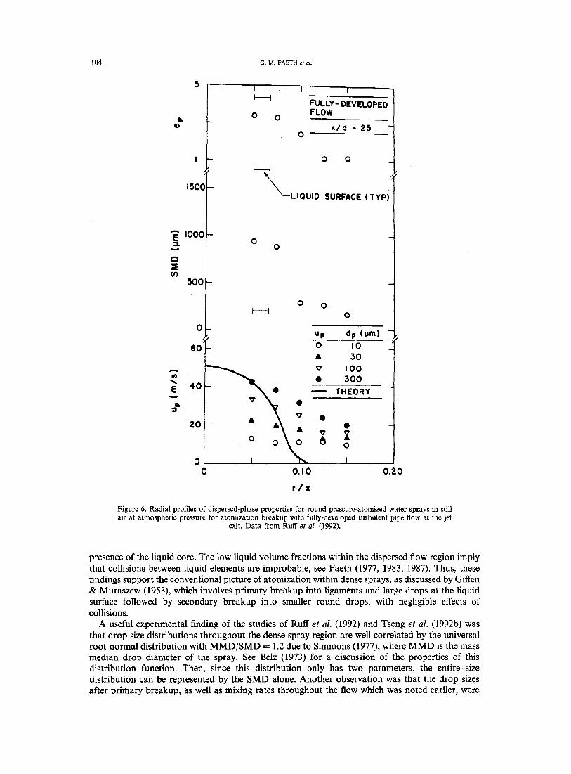
Figure 17. Streamwise location of the onset of turbulent primary breakup for round liquid jets injected into still gases. From Wu e t al. (1995).
of WeLA for the measurements is not --3/5 as suggested by [10], however, but can be represented better by the following empirical fit that is shown on the plot:
SMDi/A = 133WEE °74 [11]
Notably, the powers of WeLA in [10] and [11] agree within experimental uncertainties while the rather large coefficient of [11] is quite plausible because (go/go) 6/5 is large for fully-developed turbulent pipe flow, see Laufer (1950). Thus, the main ideas used to develop [10] appear to be plausible.
The next step involved developing an expression for the distance from the jet exit, xi, where turbulent primary breakup is initiated. Wu et al. (1991, 1992, 1995) and Wu & Faeth (1993) also developed a phenomenological analysis for xi assuming that the eddy convects along the surface of the liquid core with a velocity ~7o, that the ligament developed by the eddy moves radially outward with the characteristic eddy velocity in the inertial range, and that the critical drop at the onset of breakup separates from the ligament at the characteristic time for Rayleigh breakup, see Wu et al. (1992) for discussion of other possible characteristic times. These considerations finally lead to the following expression for the distance from the jet exit where turbulent primary breakup begins:
x i / A = Cxt(~o/g'o)9/SWec °'4 [12]
where Cxt is a constant of proportionality while (Uo/t~'o) 9/5 also is a constant for fully-developed turbulent pipe flow.
Available measurements of xi are plotted according to [12] in figure 17. The correlation of available data, for the same range of properties as figure 16, is seen to be quite good. As before, however, the power of WerA is not --0.4 as suggested by [12] but can be better represented by the following empirical fit, which is shown on the plot:
x i / A = 3890We~ -°'67 [13]

120 ; o .M. FAETH et at.
Similar to the expression for SMDi, the power of WeLA in [13] is not very different from the predicted power in [12], while the large coefficient in [13] can be anticipated because (a/fo) 9/5 in [12] is large for fully-developed turbulent pipe flow.
Subsequent work by Wu & Faeth (1993) showed that aerodynamic effects modified [11] and [13] somewhat for PL/Po < 500. In addition, the combined criteria for the presence of turbulent primary breakup along the surface of the liquid core, represented by figure 15 and [13], correspond to a different viewpoint than the classical criteria for the wind-induced and atomization breakup regimes, see Faeth (1990). Thus, more work is needed to establish the relationship between turbulent primary breakup and earlier definitions of atomization breakup regimes. Finally, Wu & Faeth (1995) have identified a range of conditions where turbulent primary breakup ends along the liquid surface before the end of the liquid core was reached, and have successfully correlated conditions for the end of breakup with turbulence properties in the large-eddy subrange of the turbulence spectrum. However, the properties of drops produced by primary breakup in the large eddy subrange, as well as for conditions where Kolmogorov scales are reached that were mentioned earlier, must still be resolved.
4.3. Breakup outcomes
With conditions for the onset of turbulent primary breakup established, the next issues include breakup outcomes, e.g. the variation of drop velocity and size distributions with increasing distance from the jet exit. Similar to the properties of secondary breakup, drop sizes satisfied the universal root normal distribution with MMD/SMD = 1.2 due to Simmons (1977), and drop velocity distributions were uniform, after turbulent primary breakup. Thus, drop size and velocity distributions will be represented by the SMD and mass-averaged velocities in the following.
10Z _ Liquid d (ram) rio (m/s)
I0 0
10 - I
A
Water 9.5 4> 21
Water 6.4 IO 16
A 58
Water 3.6 IO 35
Glycerol 42% 6.4 [] 32
n-Heptane 6.4 V 20
0' 40 (> 47
• 19 • 22 O 28 • 40
A 81 A 109
~1 38 O 38(He)
0 43 tl 57 ~ 79 ~ 9 9
45
J Uplfio = 1
v A r'O°©e~ e°
eo [] D
D
~pl~o
<> • 0
<>
A
V
S ~ e A
A rmO
[] []
V
Vplfio = 0.07
[] 0 t> 0
o O
0
0 ~pl~o
O
0 0
o <> O
A I ~ I i i i I I I i I 10-2 , I
Io -l io o 101 10 2
x/d
Figure 18. Mass-averaged drop velocities after turbulent primary breakup as a function of distance from the jet exit. From Wu et al. (1992).
STRUCTURE AND BREAKUP PROPERTIES OF SPRAYS 121
l0 t
I0 0
,<
10_i
10 -2
x/d pL/pG d(mm) . .
ml. 1 4 6 10 25 50 100
426 9.5 a ID - I~ ]N~N~] 213 9.5a • - • - - [ N ~ ' N ~
6.2 [] - O - • 0 0 - [ x , . ~ N I
104 6.2 • - • - -O - - - O / L N N ~ [
afrom Tseng e t al. (1992) Q ~ _ . /
~fromWuetal . (1992) 6 , ~ ~ # ~ ' ~ g A O I r ~ Intaetcore from Ruff e t al. (1991) , ~ , . ~ O ~ ~ q ' length
m
50
[] ~ - o . . . . . 316. ~ - - o - ~ , ÷ ~ , ~ ' f ~ - 957 6.4 b [] A ,~. - A A ~X
~.~" \ r h e o ~ c ~ l 867 9.5a.c m _ _ 0 0 0 Q J p red ic t ion 6.4 b m O • ~ O ® ®
/ 6.2 ~ - O - • 0 3.6 b [] V - ~ ~ V
594 6.4 b rn
i I i iI i J I iI I i r II I I J iI I t 10-3 10 -2 10-I 10 0 101
x / ( A W e L A 1/2)
100
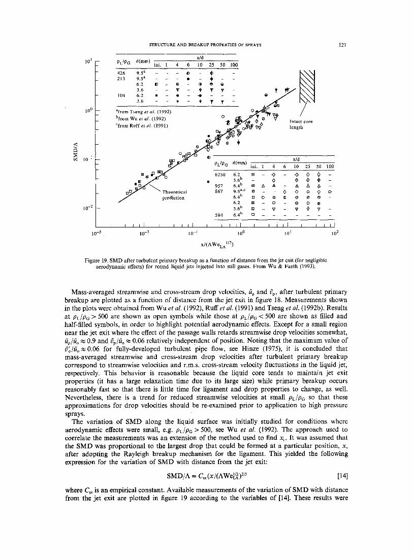
J iI 102
Figure 19. S M D after turbulent primary breakup as a function of distance from the jet exit (for negligible aerodynamic effects) for round liquid jets injected into still gases. From Wu & Faeth (1993) .
Mass-averaged streamwise and cross-stream drop velocities, gp and 6p, after turbulent primary breakup are plotted as a function of distance from the jet exit in figure 18. Measurements shown in the plots were obtained from Wu et al. (1992), Ruffet al. (1991) and Tseng et al. (1992b). Results at PL/PG > 500 are shown as open symbols while those at PL/Pc < 500 are shown as filled and half-filled symbols, in order to highlight potential aerodynamic effects. Except for a small region near the jet exit where the effect of the passage walls retards streamwise drop velocities somewhat, ~p/~7o ~ 0.9 and rYp/~ o ~ 0.06 relatively independent of position. Noting that the maximum value of f~ /go~0 .06 for fully-developed turbulent pipe flow, see Hinze (1975), it is concluded that mass-averaged streamwise and cross-stream drop velocities after turbulent primary breakup correspond to streamwise velocities and r.m.s, cross-stream velocity fluctuations in the liquid jet, respectively. This behavior is reasonable because the liquid core tends to maintain jet exit properties (it has a large relaxation time due to its large size) while primary breakup occurs reasonably fast so that there is little time for ligament and drop properties to change, as well. Nevertheless, there is a trend for reduced streamwise velocities at small PL/PG SO that these approximations for drop velocities should be re-examined prior to application to high pressure sprays.
The variation of SMD along the liquid surface was initially studied for conditions where aerodynamic effects were small, e.g. PL/PG > 500, see Wu et al. (1992). The approach used to correlate the measurements was an extension of the method used to find x~. It was assumed that the SMD was proportional to the largest drop that could be formed at a particular position, x, after adopting the Rayleigh breakup mechanism for the ligament. This yielded the following expression for the variation of SMD with distance from the jet exit:
SMD/A = C~x(x/(AWeL/~) 2/3 [14]
where Csx is an empirical constant. Available measurements of the variation of SMD with distance from the jet exit are plotted in figure 19 according to the variables of [14]. These results were

122 G.M. FAETH et al.
obtained from Ruff et al. (1992), Tseng et al. (1992b) and Wu & Faeth (1993). Some of the results illustrated in figure 19 involve PL/P6 < 500 and have been corrected for aerodynamic effects; these findings will be discussed subsequently. The correlation is seen to be quite good and can be represented by the following empirical fit:
SMD/A = 0.65(x/(AWe[/~)) 2/3 [15]
Notably, the good agreement between the measurements and the somewhat complex power relationships of [14] and [15], coupled with a coefficient of order of magnitude unity in [15], suggests that the physical principles used to derive [14] are reasonable. Another interesting feature of these results is that the SMD approaches the order of magnitude of the liquid core itself near the end of the liquid core based on the correlation measured by Grant & Middleman (1966), for fully turbulent liquid jets in still gases at atmospheric pressure where aerodynamic effects are small, namely
L~/d = 8.51We~ 2 [16]
Notably, the earlier result of Chehroudi et al. (1985), given in [1], yields qualitatively similar results but with a somewhat broader range of Lo/d. In any event, the fact that the SMD is comparable to the diameter of the liquid column near its end clearly is compatible with the liquid column breaking up as a whole in this region.
The final phase of this work was to consider aerodynamic effects on drop sizes after turbulent primary breakup, see Wu & Faeth (1993). For conditions where aerodynamic effects are important, the aerodynamic secondary breakup times for a ligament of characteristic size fi scale according to ~e i (pL/PG)l/2/uo while the Rayleigh breakup times of ligaments are proportional to (pL ~e~/a)l/z. As a result Rayleigh breakup times increase more rapidly than secondary breakup times as f~ increases. This implies a tendency for secondary and primary breakup to merge as distance from the jet exit increases. Analysis of these conditions was carried out by using [15] to define initial drop sizes and then applying the secondary breakup results of [7] to obtain the final SMD after merged primary and secondary breakup. The resulting best fit correlation of merged primary and secondary breakup is as follows:
p~SMDuZ /a = 12.9(x /A)I/3(pG/pL)3/2We[/6A/Re~ x [17]
Available measurements of merged primary and secondary breakup are plotted in figure 20 according to the variables of [17]. Measurements shown on the plot were obtained from Tseng et al. (1992b) and Wu & Faeth (1993). Equation [17] is plotted on the figure as well and is seen to provide an excellent correlation of the data, tending to support the physical ideas used in its derivation, see Wu & Faeth (1993) for the slightly improved best fit o f the data that is also shown on the plot.
The turbulent primary breakup measurements of Wu et al. (1991, 1992, 1995) and Wu & Faeth (1993) suggested three regimes of turbulent primary breakup: (1) non-aerodynamic turbulent primary breakup; (2) aerodynamically-enhanced turbulent primary breakup, observed at onset conditions; and (3) aerodynamic turbulent primary breakup, which involves merging of turbulent primary and secondary breakup. The results also indicated that the boundaries of these regimes are fixed by the liquid/gas density ratio and the relative magnitudes of characteristic Rayleigh breakup times ofligaments and the secondary breakup times of liquid fragments. The breakup times used to define these regimes were based on the SMD after primary breakup, or after the primary breakup stage of merged primary and secondary breakup, for conditions beyond the onset of breakup for present data. Thus, the characteristic Rayleigh breakup time was taken to be "tR"~(pLSMD3/a) 1/2, while the characteristic secondary breakup time was taken to be Z b ,.~ (pL/pc)l/2SMD/(lo. Then eliminating SMD from the ratio, the characteristic time ratio was taken to be:
%'R/Tb = (pL/pG)I/2(xWerA/A) 1/3 [18]
The resulting turbulent primary breakup regimes based on the available measurements of Ruff et al. (1992), Tseng et al. (1992b), Wu et al. (1991, 1992, 1995) and Wu & Faeth (1993), are illustrated in terms of PL/Pc and ZR/Zb in figure 21. The total set of measurements yields

STRUCTURE AND BREAKUP PROPERTIES OF SPRAYS 123
Q..
102
101
pL/PG d(mm) tip(m/s)
426 9.5 a • 40 213 9.5 a • 40
6.2 V 30 [] 47 3.6 0 22 A 38
104 6.2 • 30 • 47 3.6 • 22 • 38
afrom Tseng et al. (1992) 3 / %
Theoretical J / 0 • prediction ~ / , ~
/ / / , ' Correlation
/ /
100 I I I I I I I I I ) I i t I I
10 -2 10 -1 100 l0 t
( x /A) 1/3 (pG/PL)3/4 WeLAS/6ReLA -1/2
F igure 20. S M D after ae rodynamica l ly enhanced tu rbu len t p r imary b r eakup for round l iquid je ts injected in to still gases. F r o m W u & Fae th (1993).
104 -
L0
r~
103
102
Non-aerodynamic primary breakup
V
101
I L I I I i I ) I I I L i i I
10 -1 10 0 101 10 2
pL/PG d(mm) tip(m/s) pL/PG d(mm) ~o(m/s)
6230 6.2 ~ 30"0-47 ~ 67 213 9.5 c • 40 3.6 a (> 38 6.2 [] 30 [] 47 [] 67
957 6 4 a ~ 32 zx 43 A 57 ~x 79 ~x 99 915b.c 3.6 O 22 • 38 867 q5 21 ~ 40 O 47 104 6.2 • 22 /0 47-m-67
6.4 a -O 16 O- 19 O 22 (b 28 O 40 3.6 • 22 Q 58 • 81 0 109
6.2 [] 30 [] 47 [] 67 afrom Wu et al. (1992) 3.6 a ~> 35 0 38 bfrom Ruff et al. (1991)
594 6.4 a V 20 gr 45 efrom Tseng et al. (1992) 426 9.5 c • 40
"~R/'i~b~(pO/pL )I12 (x/A) I13 WeLAII3
Figure 21. Turbulent primary breakup regime map for round liquid jets injected into still gases, From Wu & Faeth (1993).
i I I~ I1 I
Aerodynamic primary I Aerodynamic breakup (enhanced) I Ill primary
[] r~O[] It~ O ( ~ ~ [] breakup I I (merged) I
I I

124 G.M. FAETH et aL
PL/Pc = 500, as the aerodynamic/non-aerodynamic transition, and ZR/% = 4, as the enhanced-aero- dynamic/merged transition.
5. CONCLUSIONS
Primary breakup along the surface of turbulent liquids was studied, considering liquid jets in still gases with fully-developed turbulent pipe flow at the jet exit (PL/Pc of 104--6230, ReLd of 90,000--780,000, Wecd of 12-3790, WeLd of 60,000--1,090,000 and Oh d of 0.0011-0.0052). The major conclusions of the study are as follows:
(1) The presence of aerodynamic phenomena for turbulent primary breakup largely is controlled by the liquid/gas density ratio. When this ratio is less than 500, aerodynamic phenomena affect both conditions at the onset of breakup, and drop sizes and velocities (to a lesser extent) after breakup.
(2) Aerodynamic enhancement of the onset of turbulent primary breakup was due to the aerodynamic pressure reduction over the tips of protruding liquid elements. This effect assists the kinetic energy of a corresponding liquid eddy relative to its surroundings to provide the surface tension energy needed to form a drop, thus allowing smaller drops to form. Phenomenological analysis based on these ideas yielded reasonable correlations of onset properties.
(3) For conditions where secondary breakup times become small in comparison to Rayleigh breakup times of turbulence-induced ligaments protruding from the surface, processes of primary and secondary breakup merge, yielding smaller drops than when aerodynamic effects are absent. The reduction of drop sizes at these conditions correlated well with results for the secondary breakup of drops due to shock disturbances.
(4) Drop-size distributions after aerodynamic turbulent primary breakup approximated the universal root normal distribution with MMD/SMD = 1.2 due to Simmons (1977), similar to observations of other drop breakup processes as well as drops in the multiphase mixing layers of pressure-atomized sprays. Additionally, mass-averaged drop velocities after aerodynamic turbulent primary breakup approximate mean and rms velocity fluctuations of the liquid in the streamwise and cross-stream directions, respectively, although there was a tendency for streamwise velocities to be somewhat reduced by aerodynamic effects.
A major issue still open involves primary breakup of non-turbulent liquids and the relevance of the classical primary breakup theories of Taylor (1963) and Levich (1962). Results discussed here indicate that it is difficult to observe the non-turbulent primary breakup mechanism. The main problems are effects of liquid disturbances, the intrusion of secondary breakup and weak aerodynamic effects for most liquids at normal temperature and pressure where measurements are most convenient. Until these experimental difficulties are resolved, understanding of this important primary breakup mechanism will remain limited. The properties of turbulent primary breakup also merit additional study, particularly behavior in the large eddy subrange of the turbulence spectrum, as well as for conditions where drop formation is controlled by the smallest turbulent eddies in the region of the Kolmogorov microscales.
Acknowledgements--The author's research on sprays has been supported by the U.S. Air Force Office of Scientific Research, Grant Nos AFOSR-89-0516, F49620-92-T-0399 and F49620-95-I-0364, under the technical management of J. M. Tishkoff; and by the U.S. Office of Naval Research, Grant Nos N00014-95-1- 0234 and N00014-89-J-1199, under the technical management of E. P. Rood and G. D. Roy. The authors would like to acknowledge useful discussions with W.-H. Chou, G. A. Ruff and L.-K. Tseng. The U.S. Government is authorized to reproduce and distribute copies for governmental purposes notwithstanding any copyright notation thereon.
REFERENCES
Annamalai, J. A. & Ryan, W. 1992 Interactive processes in gasification and combustion. Part 1: Liquid drop arrays and clouds. Prog. Energy Combust. Sci. 9, 221-295.

S T R U C T U R E A N D B R E A K U P P R O P E R T I E S OF SPRAYS 125
Arai, M., Shimizu, M. & Hiroyasu, H. 1985 Break-up length and spray angle of high speed jet. Proc. 3rd Int. Conf. on Liquid Atomization and Spray Systems, pp. IB/4/1-IB/4/10.
Arai, M., Shimizu, M. & Hiroyasu, H. 1988 Break-up length and spray formation mechanisms of a high speed liquid jet. Proc. 4th Int. Conf. on Liquid Atomization and Spray Systems, pp. 177-184.
Belz, M. H. 1973 Statistical Methods in the Process Industries, pp. 103-104. Wiley, New York. Chehroudi, B., Onuma, Y., Chen, S.-H. & Bracco, F. V. 1985 On the intact core of full-cone sprays.
SAE Paper No. 850126. Clift, R., Grace, J. R. & Weber, M. E. 1978 Bubbles, Drops and Particles, p. 346. Academic Press,
New York. De Juhasz, K. J., Zahm, O. F. Jr & Schweitzer, P. H. 1932 On the formation and dispersion of
oil sprays. Bulletin No. 40, Engineering Experimental Station, Pennsylvania State University, University Park, PA, pp. 63-68.
Engel, O. G. 1958 Fragmentation of waterdrops in the zone behind an air shock. J. Res. Nat. Bur. Standards 60, 245-280.
Faeth, G. M. 1977 Current status of droplet and liquid combustion. Prog. Energy Combust. Sci. 3, 191-224.
Faeth, G. M. 1983 Evaporation and combustion in sprays. Prog. Energy Combust. Sci. 9, 1-76. Faeth, G. M. 1987 Mixing, transport and combustion in sprays. Prog. Energy Combust. Sci. 13,
293-345. Faeth, G. M. 1990 Structure and atomization properties of dense turbulent sprays. Twenty-Third
Symp. (Int.)on Combustion, The Combustion Institute, Pittsburgh, PA, pp. 1345-1352. Gel'fand, B. E, Gubin, S. A. & Kogarko, S. M. 1974 Various forms of drop fractionation in shock
waves and their special characteristics. Inzh.-Fiz. Zh. 27, 119 126. Giffen, E. & Muraszew, A. 1953 The Atomization of Liquid Fuels. Chapman & Hall, London. Hanson, A. R., Domich, E. G. & Adams, H. S. 1963 Shock-tube investigation of the breakup of
drops by air blasts. Phys. Fluids 6, 1070-1080. Harrje, D. T. & Reardon, F. H. 1972 Liquid rocket combustion instability. NASA SP-194,
pp. 49-55. Hinze, J. O. 1948 Critical speeds and sizes of liquid globules. Appl. Sci. Res. 11, 273-287. Hinze, J. O. 1955 Fundamentals of the hydrodynamic mechanism of splitting in dispersion
processes. AIChE Jl 1, 289-295. Hinze, J. O. 1975 Turbulence, 2nd Edn, pp. 427, 724-734. McGraw-Hill, New York. Hiroyasu, H., Shimizu, M. & Arai, M. 1982 The breakup of a high speed jet in a high pressure
gaseous atmosphere. Proc. 2nd Int. Conf. on Liquid Atomization and Spray Systems, University of Wisconsin, Madison, WI, p. 69.
Hiroyasu, H., Arai, M. & Shimizu, M. 1991 Break-up length of a liquid jet and internal flow in a nozzle. Proc. 5th Int. Conf. on Liquid Atomization and Spray Systems, pp. 275-282.
Hoyt, J. W. & Taylor, J. J. 1977a Turbulence structure in a water jet discharging in air. Phys. Fluids 20, Pt II, $253-$257.
Hoyt, J. W. & Taylor, J. J. 1977b Waves on waterjets. J. Fluid Mech. 88, 119-127. Hsiang, L.-P. & Faeth, G. M. 1992 Near-limit drop deformation and secondary breakup. Int. J.
Multiphase Flow 18, 635-652. Hsiang, L.-P. & Faeth, G. M. 1993 Drop properties after secondary breakup. Int. J. Multiphase
Flow 19, 721-735. Hsiang, L.-P. & Faeth, G. M. 1995 Drop deformation and breakup due to shock wave and steady
disturbances. Int. J. Multiphase Flow 21, 545-560. Hsiang, L.-P., Chou, W.-H. & Faeth, G. M. 1995 Temporal variation of drop properties and
formation rates during secondary breakup. AIAA Paper 95-2426. Karasawa, T., Tanaka, M., Abe, K., Shiga, S. & Kurabayashi, T. 1992 Effects of nozzle
configuration on the atomization of a steady spray. Atom. Sprays 2, 411-426. Krzeczkowski, S. A. 1980 Measurement of liquid droplet disintegration mechanisms. Int. J.
Multiphase Flow 6, 227-239. Lane, W. R. 1951 Shatter of drops in streams of air. Ind. Engng Chem. 43, 1312-1317. Laufer, J. 1954 The structure of turbulence in fully developed pipe flow. NACA Report 1174.

126 G.M. FAETH et al.
Law, C. K. 1982 Recent advances in droplet vaporization and combustion. Prog. Energy Combust. Sci. 8, 169-201.
Lee, D. W. & Spencer, R. C. 1933 Photomicrographic studies of fuel sprays. NACA Report 454. Lefebvre, A. H. 1980 Airblast atomization. Prog. Energy Combust. Sci. 6, 223-246. Lefebvre, A. H. 1983 Gas Turbine Combustion. Hemisphere, New York. Lefebvre, A. H. 1989 Atomization and Sprays, pp. 27-78, 201-272, Hemisphere, New York. Levich, V. G. 1962 Physicochemical Hydrodynamics, pp. 636-546. Prentice-Hall, Englewood Cliffs,
NJ. Loparev, V. P. 1975 Experimental investigation of the atomization of drops of liquid under
conditions of a gradual rise of the external forces. Izv. Akad. Nauk SSSR. Mekh. Zh. Gaza 3, 174-178.
Mansour, A. & Chigier, N. 1994 Effect of turbulence on the stability of liquid jets and resulting droplet size distributions. Atom. Sprays 4, 583-604.
Miesse, C. C. 1955 Correlation of experimental data on the disintegration of liquid jets. Ind. Engng Chem. 470, 1690-1697.
Phinney, R. E. 1973 The breakup of a turbulent jet in a gaseous atmosphere. J. Fluid Mech. 63, 689-701.
Ranger, A. A. & Nicholls, J. A. 1969 Aerodynamic shattering of liquid drops. AIAA Jl 7, 285-290. Ranz, W. E. 1958 Some experiments on orifice sprays. Can. J. Chem. Engng 36, 175-181. Reinecke, W. G. & McKay, W. L. 1969 Experiments on waterdrop breakup behind Mach 3 to 12
shocks. Sandia Corp. Report SC-CR-70-6063. Reinecke, W. G. & Waldman, G. D. 1970 A study of drop breakup behind strong shocks with
applications to flight. Avco Report AVSD-0110-70-77. Reitz, R. D. & Bracco, F. V. 1982 Mechanism of atomization of a liquid jet. Phys. Fluids 25,
1730-1742. Ricou, F. P. & Spalding, D. B. 1961 Measurements of entrainment by axisymmetrical turbulent
jets. J. Fluid Mech. 11, 21-32. Ruff, G. A. & Faeth, G. M. 1995 Non-intrusive measurements of the structure of dense sprays.
Prog. Astro. Aero. In press. Ruff, G. A., Sagar, A. D. & Faeth, G. M. 1989 Structure of the near-injector region of
pressure-atomized sprays. AIAA J1 27, 901-908. Ruff, G. A., Bernal, L. P. & Faeth, G. M. 1991 Structure of the near-injector region of
non-evaporating pressure-atomized sprays. J. Prop. Power 7, 221-230. Ruff, G. A., Wu, P.-K., Bernal, L. P. & Faeth, G. M. 1992 Continuous- and dispersed-phase
structure of dense non-evaporating pressure-atomized sprays. J. Prop. Power 8, 280-289. Schlichting, H. 1979 Boundary Layer Theory, 7th Edn, pp. 234-235, 599. McGraw-Hill, New York. Simmons, H. C. 1977 The correlation of drop-size distributions in fuel nozzle sprays. J. Engng
Power 99, 309-319. Simpkins, P. G. & Bales, E. J. 1972 Water-drop response to sudden accelerations. J. Fluid Mech.
55, 629~539. Sirignano, W. A. 1983 Fuel droplet vaporization and spray combustion theory. Prog. Energy
Combust. Sci. 9, 291-322. Smith, A. M. O. 1960 Remarks on transition in a round tube. J. Fluid Mech. 7, 565-576. Taylor, G. I. 1963 Generation of ripples by wind blowing over a viscous liquid. In The Scientific
Papers of Sir Geoffrey Ingram Taylor (Edited by Batchelor, G. K.), Vol. III, pp. 244-254. Cambridge University Press, Cambridge, England.
Tennekes, H. & Lumley, J. L. 1972 A First Course in Turbulence, pp. 226, 248-286. MIT Press, Cambridge, MA.
Tseng, L.-K., Ruff, G. A. & Faeth, G. M. 1992a Effects of gas density on the structure of liquid jets in still gases. AIAA Jl 30, 1537-1544.
Tseng, L.-K., Wu, P.-K. & Faeth, G. M. 1992b Dispersed-phase structure of pressure-atomized sprays at various gas densities. J. Prop. Power 8, 1157-1166.
Tseng, L.-K., Ruff, G. A., Wu, P.-K. & Faeth, G. M. 1995 Continuous- and dispersed phase structure of pressure atomized sprays. Prog. Astro. Aero. In press.
White, F. M. 1974 Viscous Fluid Flow. McGraw-Hill, New York.

STRUCTURE AND BREAKUP PROPERTIES OF SPRAYS 127
Wierzba, A. & Takayama, K. 1988 Experimental investigation of the aerodynamic breakup of liquid drops. AIAA Jl 26, 1329-1335.
Wu, K.-J., Su, C.-C., Steinberger, R. L., Santavicca, D. A. & Bracco, F. V 1983 Measurements of the spray angle of atomizing jets. J. Fluid Engng 105, 406-415.
Wu, K.-J., Coghe, A., Santavicca, D. A. & Bracco, F. V. 1984 LDV measurements of drop velocity in diesel-type sprays. AIAA Jl 22, 1263-1270.
Wu, P.-K. & Faeth, G. M. 1993 Aerodynamic effects on primary breakup of turbulent liquids. Atom. Sprays 3, 265-289.
Wu, P.-K. & Faeth, G. M. 1995 Onset and end of drop formation along the surface of turbulent liquid jets in still gases. Phys. Fluids A. In press.
Wu, P.-K., Ruff, G. A. & Faeth, G. M. 1991 Primary breakup in liquid/gas mixing layers. Atom. Sprays 1, 421-440.
Wu, P.-K., Tseng, L.-K. & Faeth, G. M. 1992 Primary breakup in gas/liquid mixing layers for turbulent liquids. Atom. Sprays 2, 295-317.
Wu, P.-K., Miranda, R. F. & Faeth, G. M. 1995a Effects of initial flow conditions on primary breakup of nonturbulent and turbulent round liquid jets. Atom. Sprays 5, 175-196.
Wu, P.-K., Hsiang, L.-P. & Faeth, G. M. 1995b Aerodynamic effects on primary and secondary breakup. Prog. Astro. Aero. In press.
Yokota, M., Ito, Y. & Shinoke, T. 1988 High speed photographic observations of cavitation arising in the high-speed oil-flow through a very small long orifice. 9th International Symposium on Jet Cutting Technology, Sendai, Japan, pp. 13-21.