Structure and Architectural Form of Tall Buildings - … and Architectural Form of Tall Buildings...
77
Structure and Architectural Form of Tall Buildings Mahjoub Elnimeiri, PhD, PE, MASCE Chairman cdci engineers international & Professor at IIT Member of steering group, CTBUH Chicago, USA
Transcript of Structure and Architectural Form of Tall Buildings - … and Architectural Form of Tall Buildings...
Structure and Architectural Form of Tall Buildings
Mahjoub Elnimeiri, PhD, PE, MASCE
Chairman cdci engineers international & Professor at IITMember of steering group, CTBUH
Chicago, USA
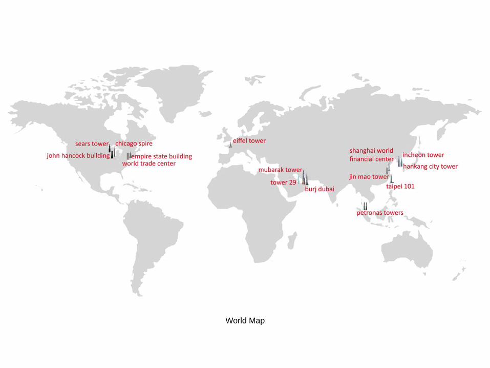
World Map

World’s Tallest Buildings Chart
Meter
1000
900
800
700
600
500
400
300
200
100
0
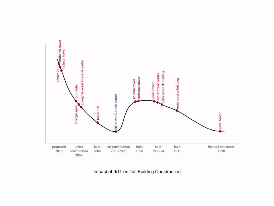
Impact of 9/11 on Tall Building Construction
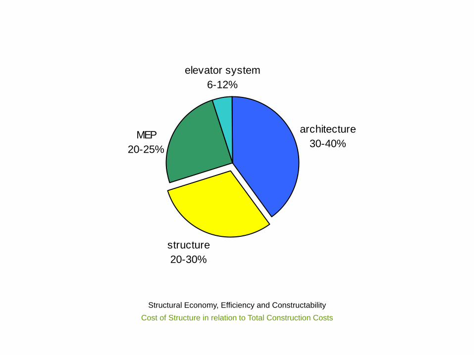
structure20-30%
MEP20-25%
elevator system6-12%
architecture30-40%
Structural Economy, Efficiency and ConstructabilityCost of Structure in relation to Total Construction Costs
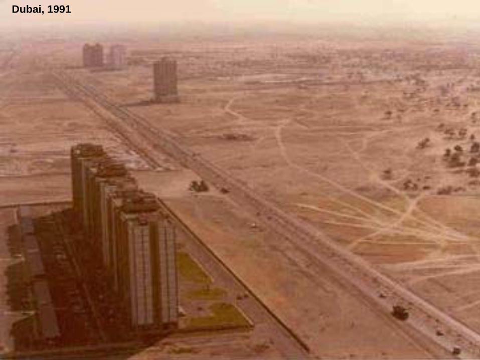
Dubai, 1991

Dubai, 2003
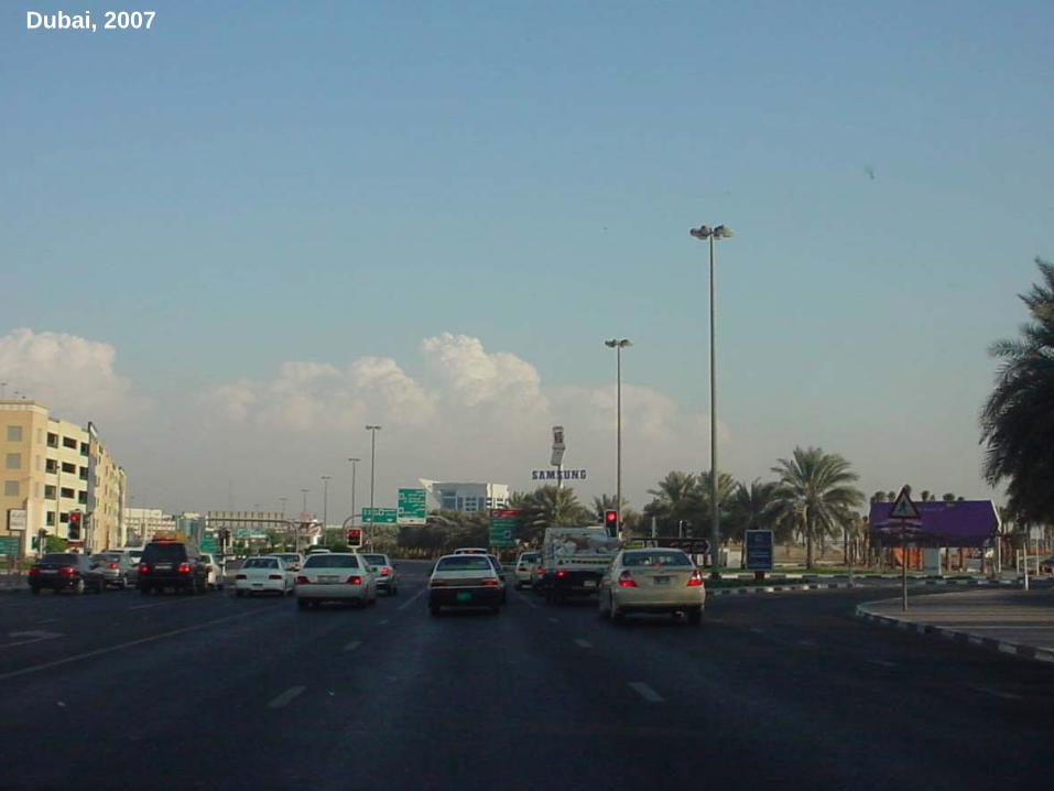
Dubai, 2007
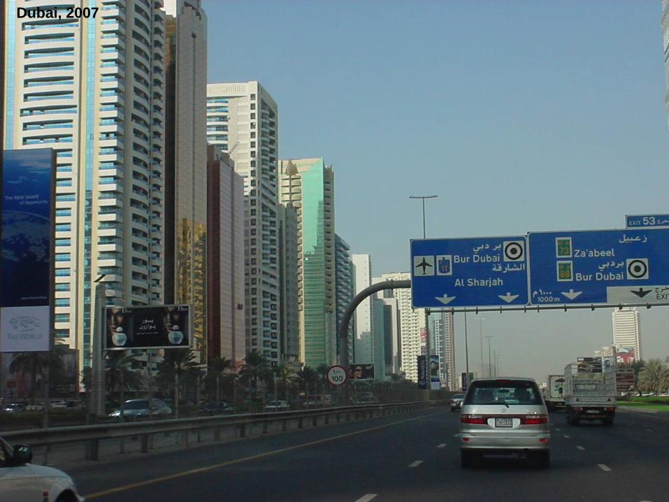
Dubai, 2007
Dubai, 2003
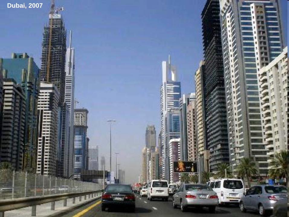
Dubai, 2007
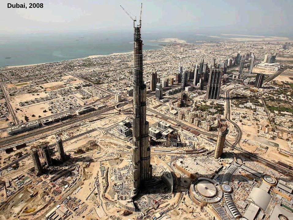
Dubai, 2008
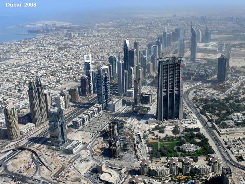
Dubai, 2008
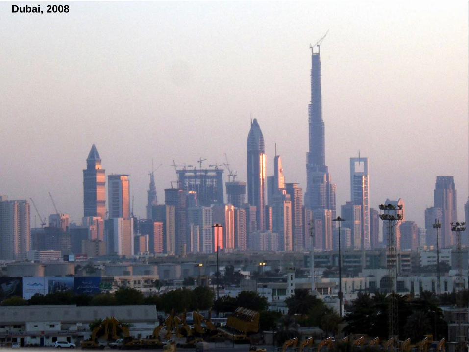
Dubai, 2008
Dubai, 2008
Dubai, 2003
Dubai, 2008
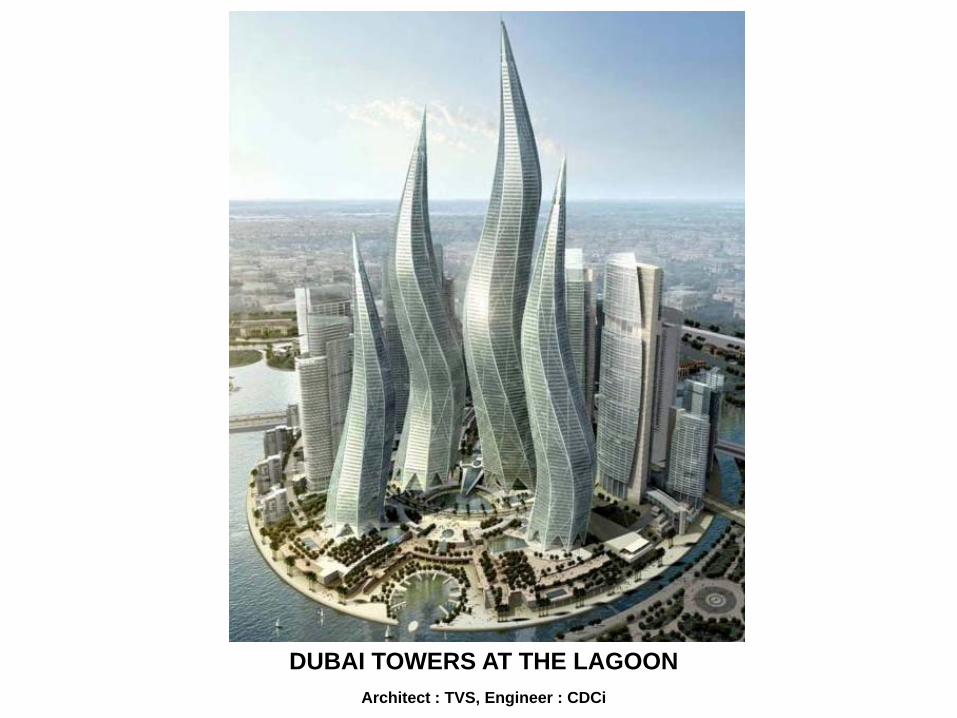
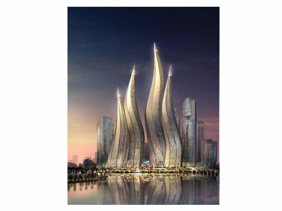
DUBAI TOWERS AT THE LAGOONArchitect : TVS, Engineer : CDCi
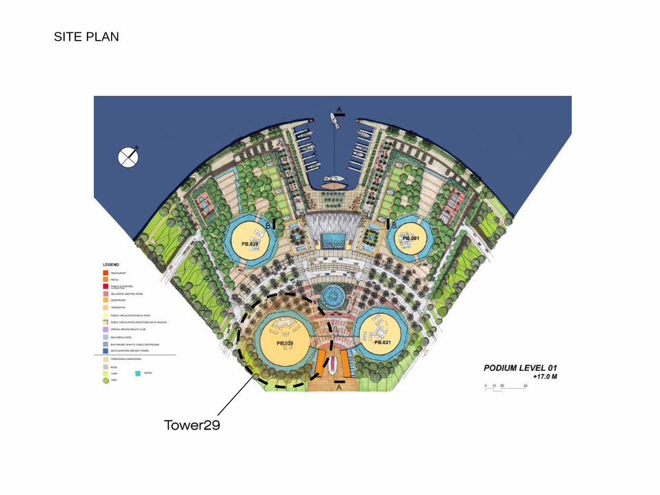
Tower29
SITE PLAN
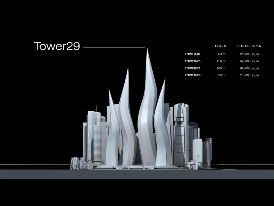
Tower29 HEIGHT BUILT-UP AREA
TOWER-01 360 m 120,000 sq. m
TOWER-20 410 m 140,000 sq. m
TOWER-21 460 m 160,000 sq. m
TOWER-29 550 m 210,000 sq. m
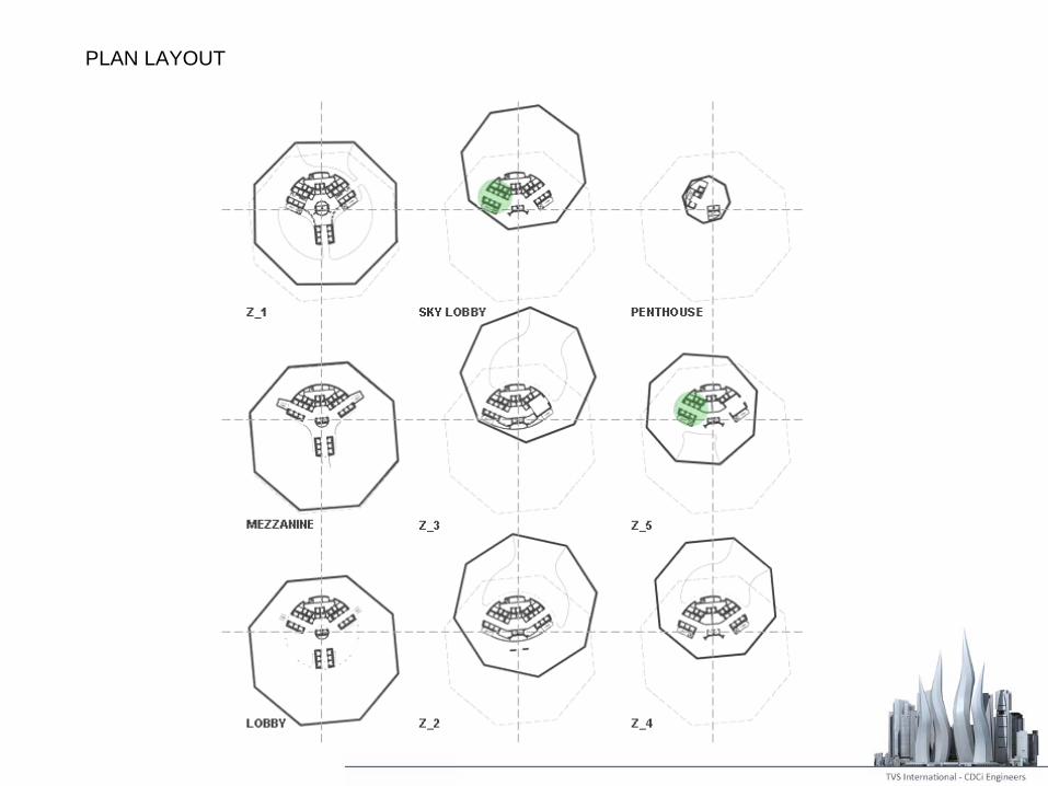
PLAN LAYOUT
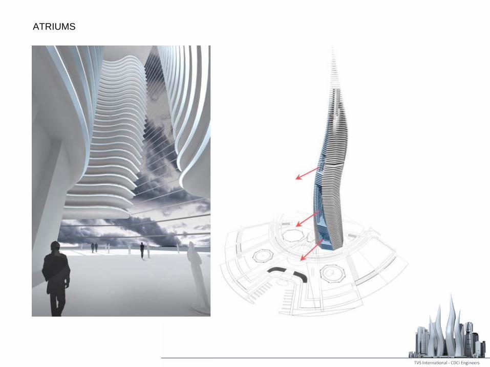
ATRIUMS
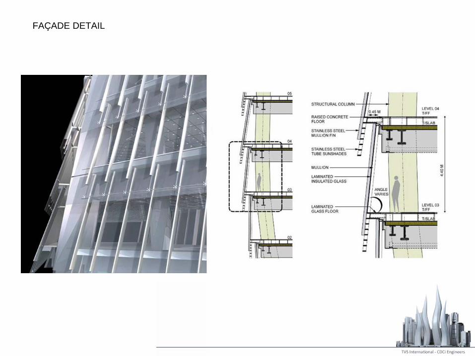
FAÇADE DETAIL
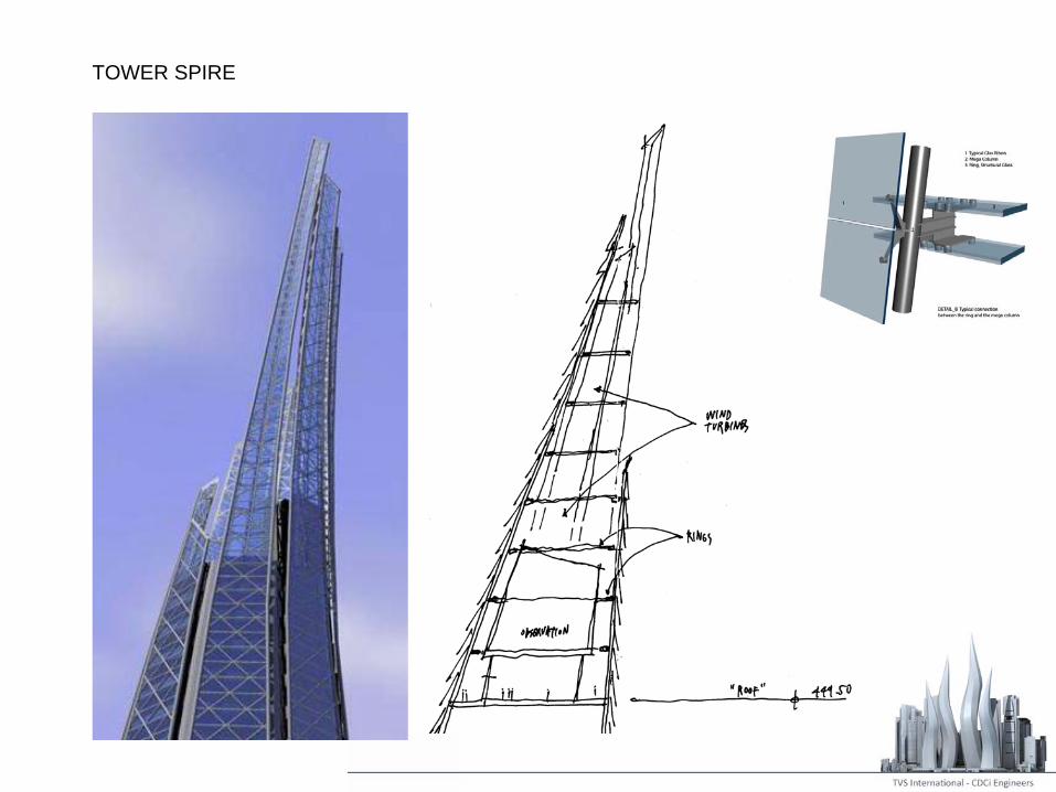
TOWER SPIRE
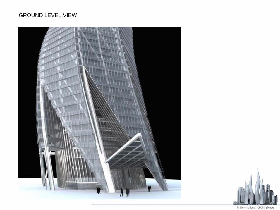
GROUND LEVEL VIEW
Height Built-up Area
Tower-01 550 m 120,000 sq. m
Tower 20 140,000 sq. m
Tower 21 160,000 sq. m
Tower 29 360 m 210,000 sq. m
SPECIAL CONSIDERATIONS
• Scale, Height
• Iconic Form: Twisting and Plan Morphing
• Location: “DUBAI”
• Grouping
• Constructability
STRUCTURE OBJECTIVE
• Preserve the Architectural Vision
• Maintain the Structural Integrity
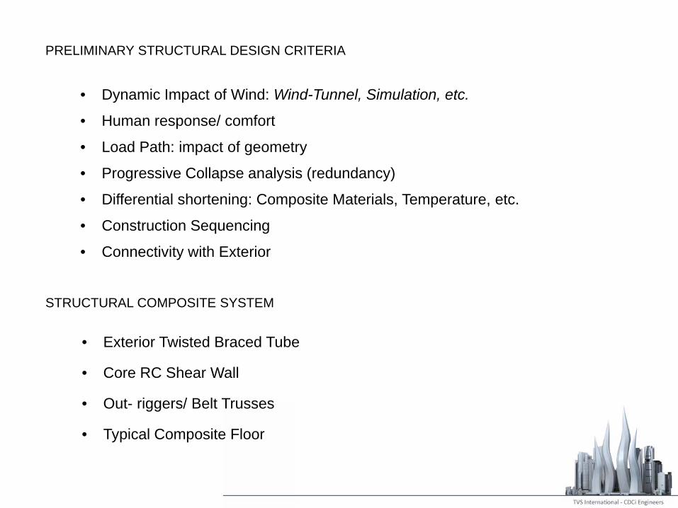
PRELIMINARY STRUCTURAL DESIGN CRITERIA
• Dynamic Impact of Wind: Wind-Tunnel, Simulation, etc.
• Human response/ comfort
• Load Path: impact of geometry
• Progressive Collapse analysis (redundancy)
• Differential shortening: Composite Materials, Temperature, etc.
• Construction Sequencing
• Connectivity with Exterior
STRUCTURAL COMPOSITE SYSTEM
• Exterior Twisted Braced Tube
• Core RC Shear Wall
• Out- riggers/ Belt Trusses
• Typical Composite Floor

• Interaction between vertical and horizontal loadings
• Appreciable movement both horizontally and downwards
• Strategy to ensure stability and stiffness
LOAD PATH : IMPACT OF GEOMETRY
Progressive Collapse analysis (redundancy):
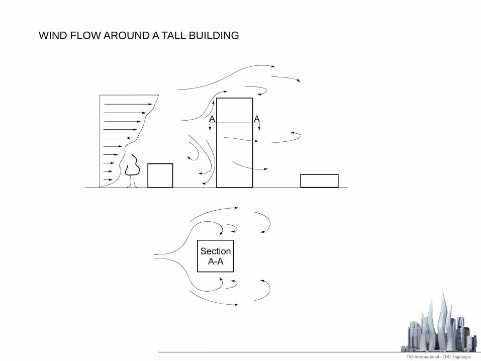
WIND FLOW AROUND A TALL BUILDING
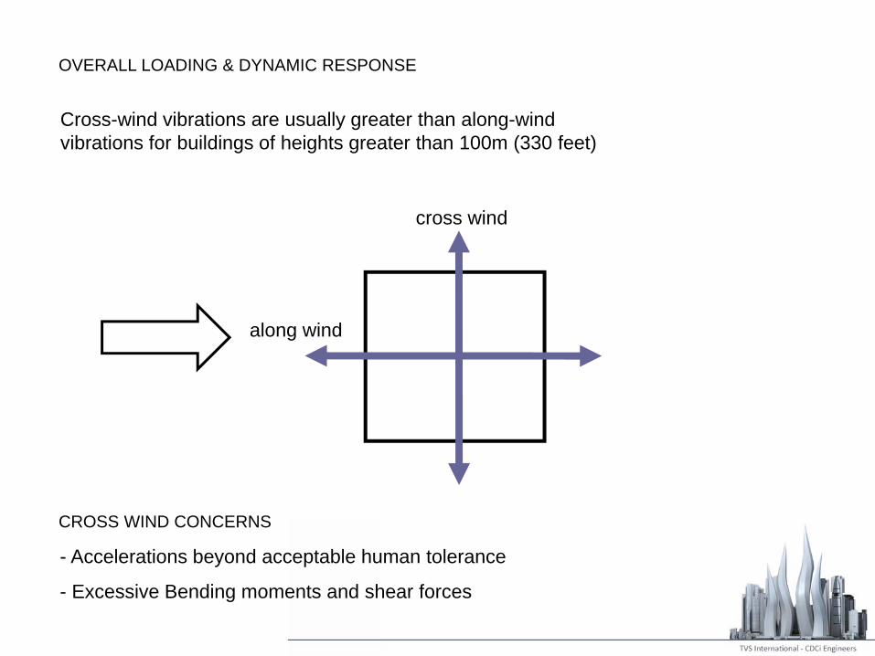
OVERALL LOADING & DYNAMIC RESPONSE
Cross-wind vibrations are usually greater than along-wind vibrations for buildings of heights greater than 100m (330 feet)
along wind
cross wind
CROSS WIND CONCERNS
- Accelerations beyond acceptable human tolerance
- Excessive Bending moments and shear forces
TORSIONAL LOADING AND RESPONSE
Two mechanisms :
• Applied moments from aerodynamic forces produced by non-uniform
pressure distributions or non-symmetric cross-sections
• Structural eccentricity between elastic center and geometric center
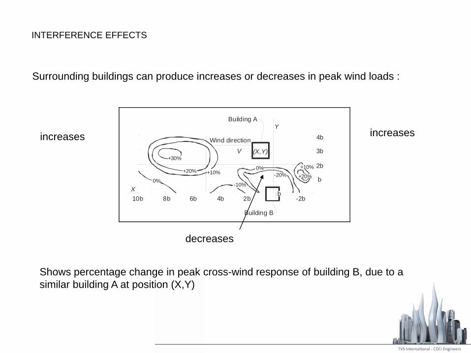
INTERFERENCE EFFECTS
Surrounding buildings can produce increases or decreases in peak wind loads :
Shows percentage change in peak cross-wind response of building B, due to a similar building A at position (X,Y)
10b 8b 6b 4b 2b -2bb
Building B
Wind direction
(X,Y)
Building A
V
b
2b
3b
4b
0%
+30%
+20% +10%
-10%
+10%
+20%
X
Y
0%-20%
increases increases
decreases

AUXILIARY DAMPING
Visco-elastic Damper
used on World Trade Center buildings, New York
F/2 F/2
Steel flange
V.E. material
Centreplate
F
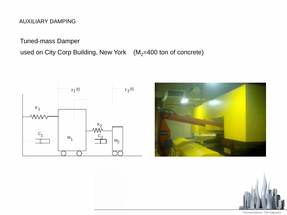
used on City Corp Building, New York (M2=400 ton of concrete)
K
CM
K
CM
yy
1
11
2
22
21 (t) (t)
AUXILIARY DAMPING
Tuned-mass Damper
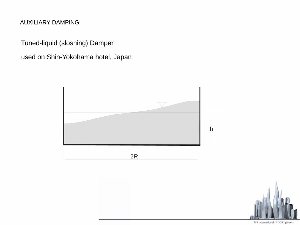
used on Shin-Yokohama hotel, Japan
h
2R
AUXILIARY DAMPING
Tuned-liquid (sloshing) Damper

SHAPING BUILDINGS TO REDUCE AERODYNAMIC EXCITATION & RESPONSE
• Determination of cross-wind response
• Controlling the cross-wind force spectrum
PARAMETRIC STUDY
• Tapering
• Softening the edge in plan
• Porosity
• Twisting
• Plan Morphing
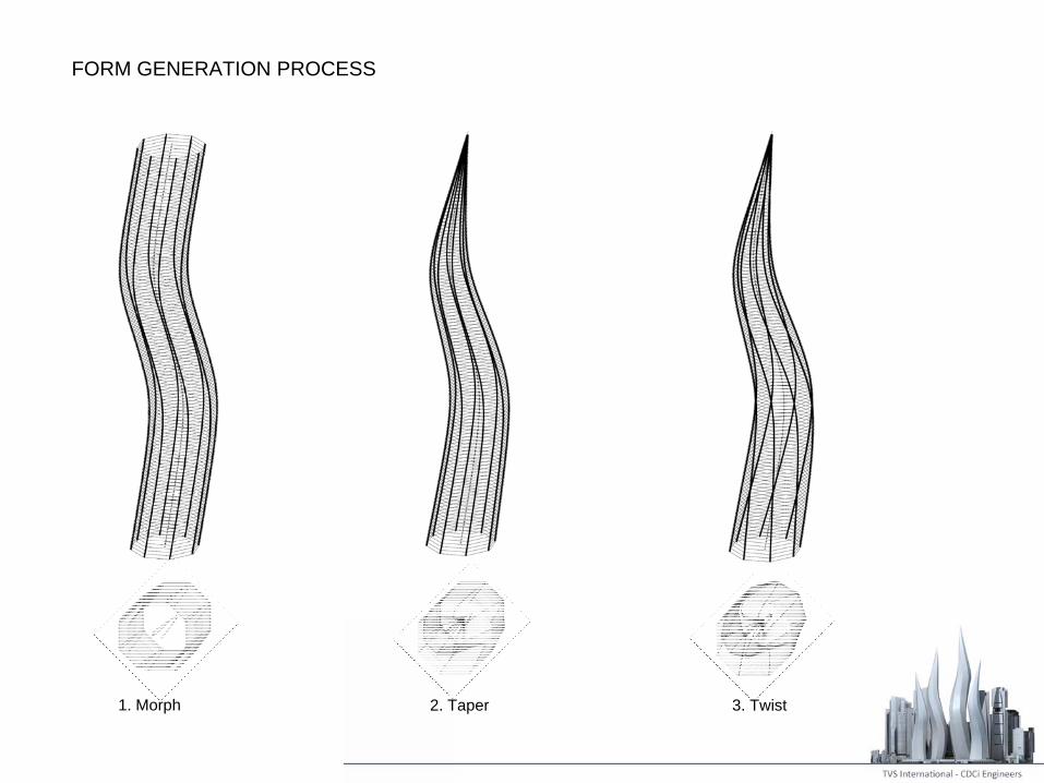
FORM GENERATION PROCESS
1. Morph 2. Taper 3. Twist
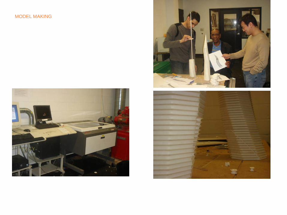
MODEL MAKING
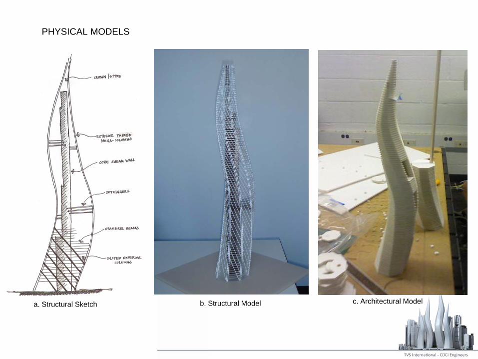
PHYSICAL MODELS
c. Architectural Modelb. Structural Modela. Structural Sketch
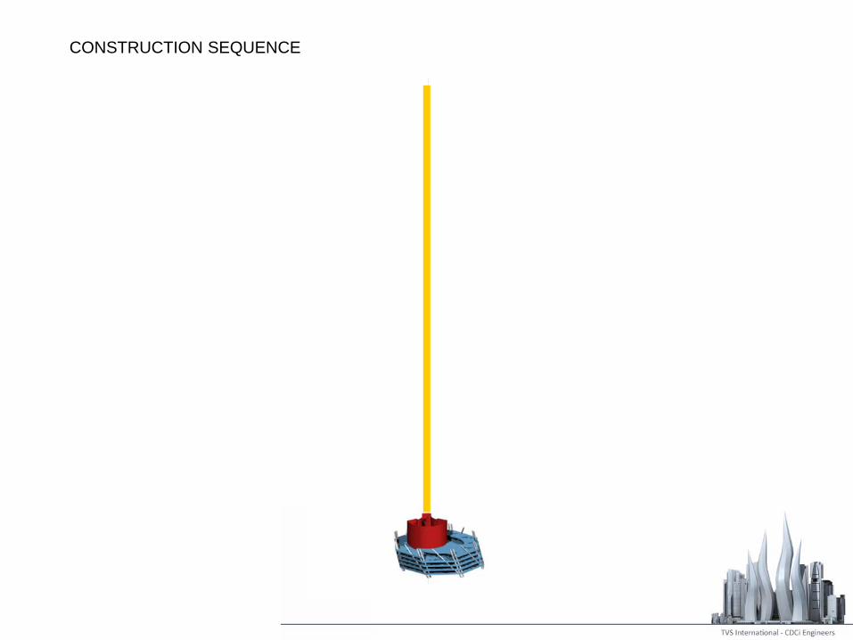
CONSTRUCTION SEQUENCE
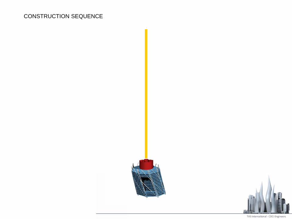
CONSTRUCTION SEQUENCE

CONSTRUCTION SEQUENCE

CONSTRUCTION SEQUENCE
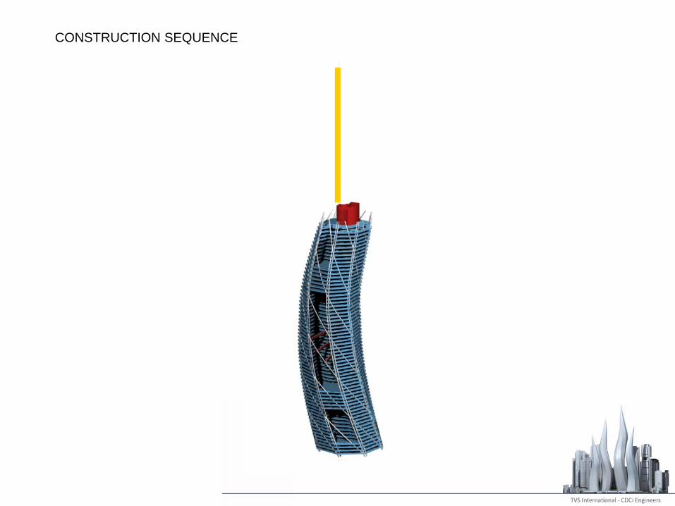
CONSTRUCTION SEQUENCE

CONSTRUCTION SEQUENCE

CONSTRUCTION SEQUENCE
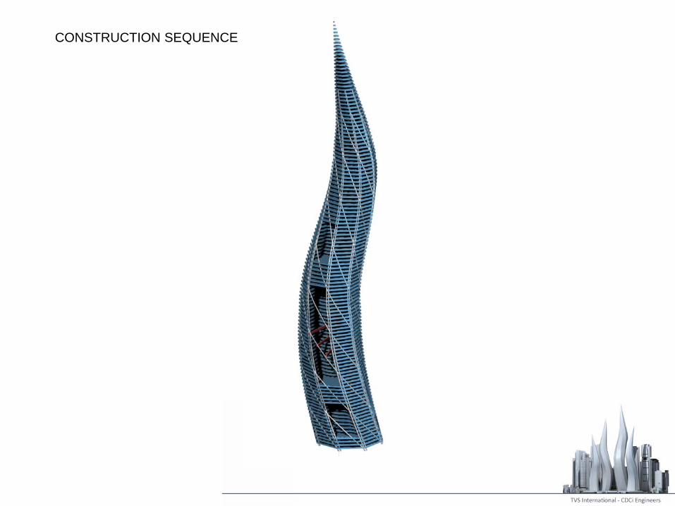
CONSTRUCTION SEQUENCE
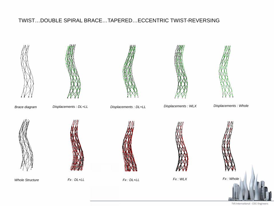
TWIST…DOUBLE SPIRAL BRACE…TAPERED…ECCENTRIC TWIST-REVERSING
Displacements : WLX Whole
Fx : DL+LL Fx : 1 DL+LL Fx : WLX
Displacements : DL+LL Displacements : DL+LLBrace diagram Displacements : DL+LL Displacements : DL+LL Displacements : WLX Displacements : Whole
Whole Structure Fx : DL+LL Fx : DL+LL Fx : WLX Fx : Whole
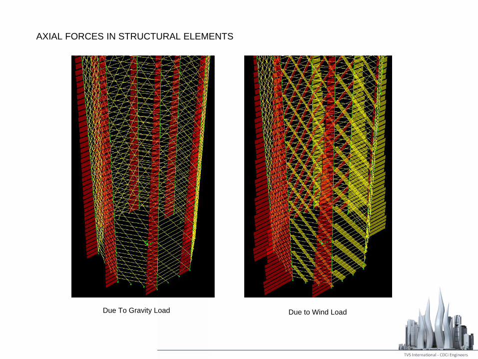
AXIAL FORCES IN STRUCTURAL ELEMENTS
Due To Gravity Load Due to Wind Load
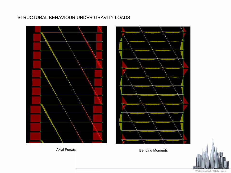
STRUCTURAL BEHAVIOUR UNDER GRAVITY LOADS
Axial Forces Bending Moments
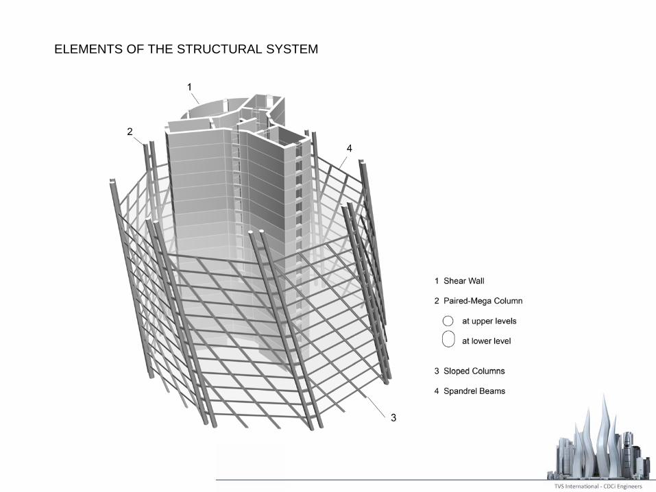
ELEMENTS OF THE STRUCTURAL SYSTEM
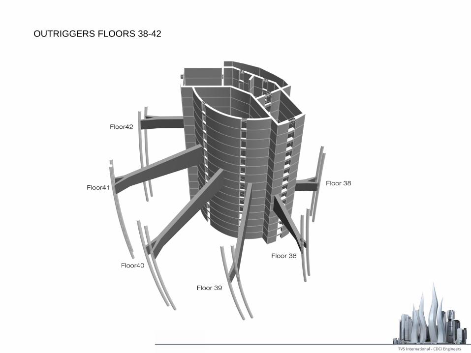
OUTRIGGERS FLOORS 38-42
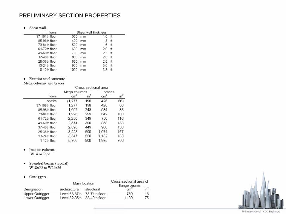
PRELIMINARY SECTION PROPERTIES
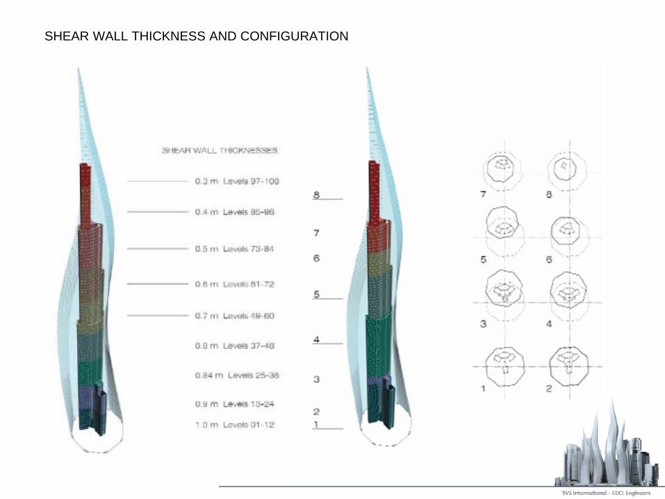
SHEAR WALL THICKNESS AND CONFIGURATION
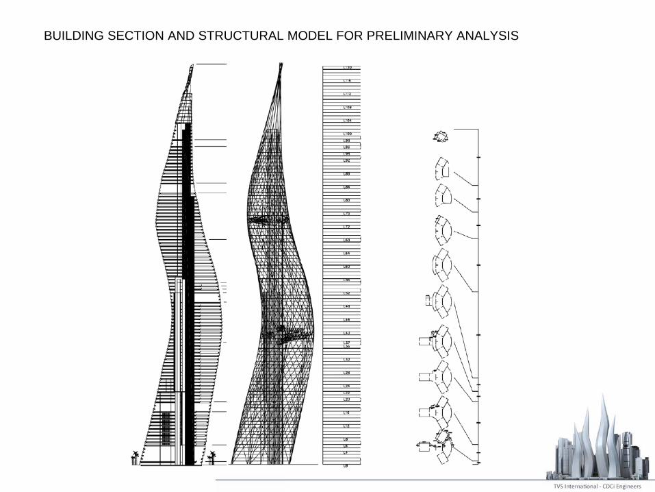
BUILDING SECTION AND STRUCTURAL MODEL FOR PRELIMINARY ANALYSIS

INTERIOR COLUMNS
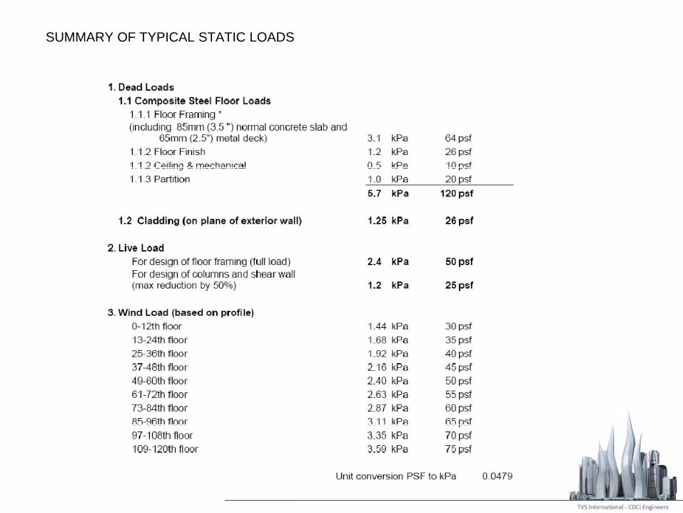
SUMMARY OF TYPICAL STATIC LOADS
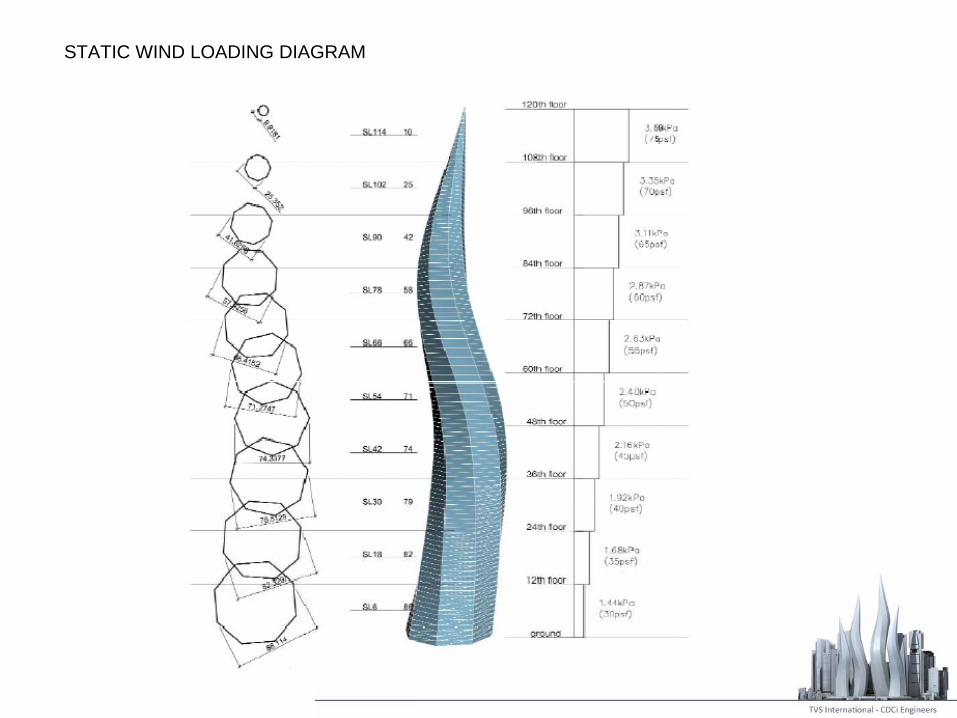
STATIC WIND LOADING DIAGRAM
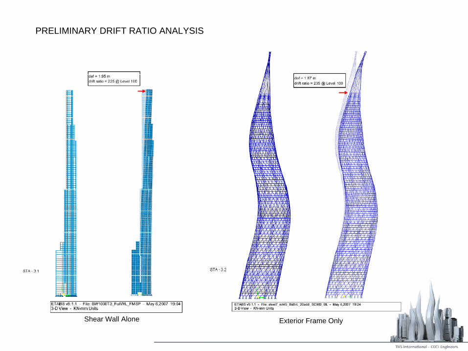
PRELIMINARY DRIFT RATIO ANALYSIS
Shear Wall Alone Exterior Frame Only

PRELIMINARY DRIFT RATIO ANALYSIS
Shear Wall + Exterior Frame Shear Wall + Exterior Frame + Outriggers

TIP DEFLECTION AND DRIFT RATIO
Def = 0.60Drift ratio = 733 @ Level 100
Def = 0.56Drift ratio = 786 @ Level 100
Wind X Wind Y

EFFECTS OF TWIST ON SLAB DUE TO SHEAR STRESSES
3D ViewPlan
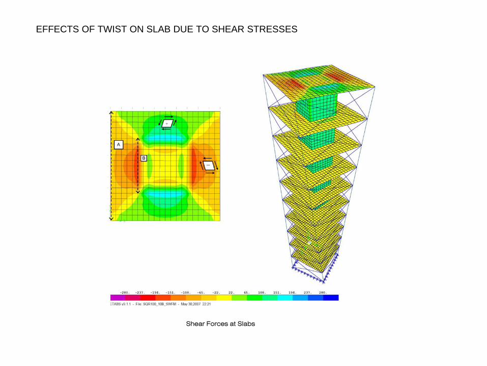
EFFECTS OF TWIST ON SLAB DUE TO SHEAR STRESSES
Shear Forces at Slabs
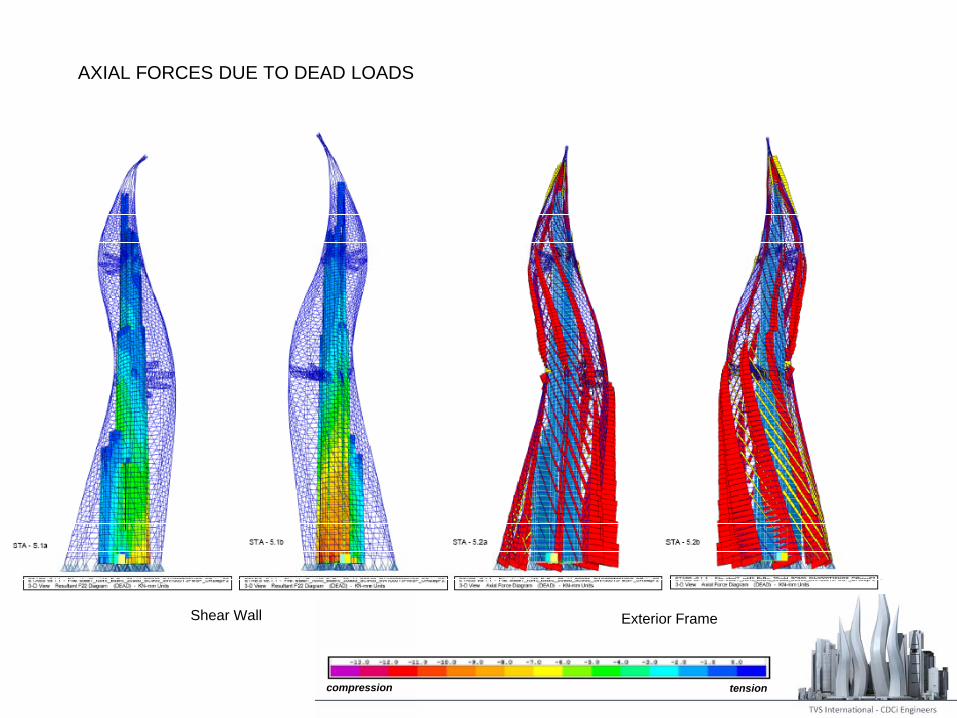
AXIAL FORCES DUE TO DEAD LOADS
Shear Wall Exterior Frame
tensioncompression
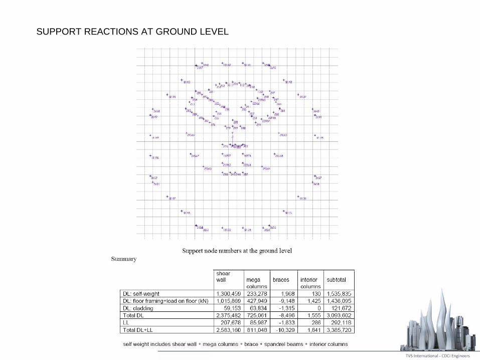
SUPPORT REACTIONS AT GROUND LEVEL
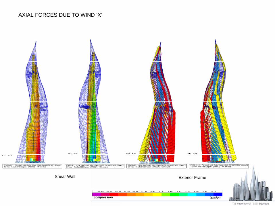
AXIAL FORCES DUE TO WIND ‘X’
compression tension
Shear Wall Exterior Frame
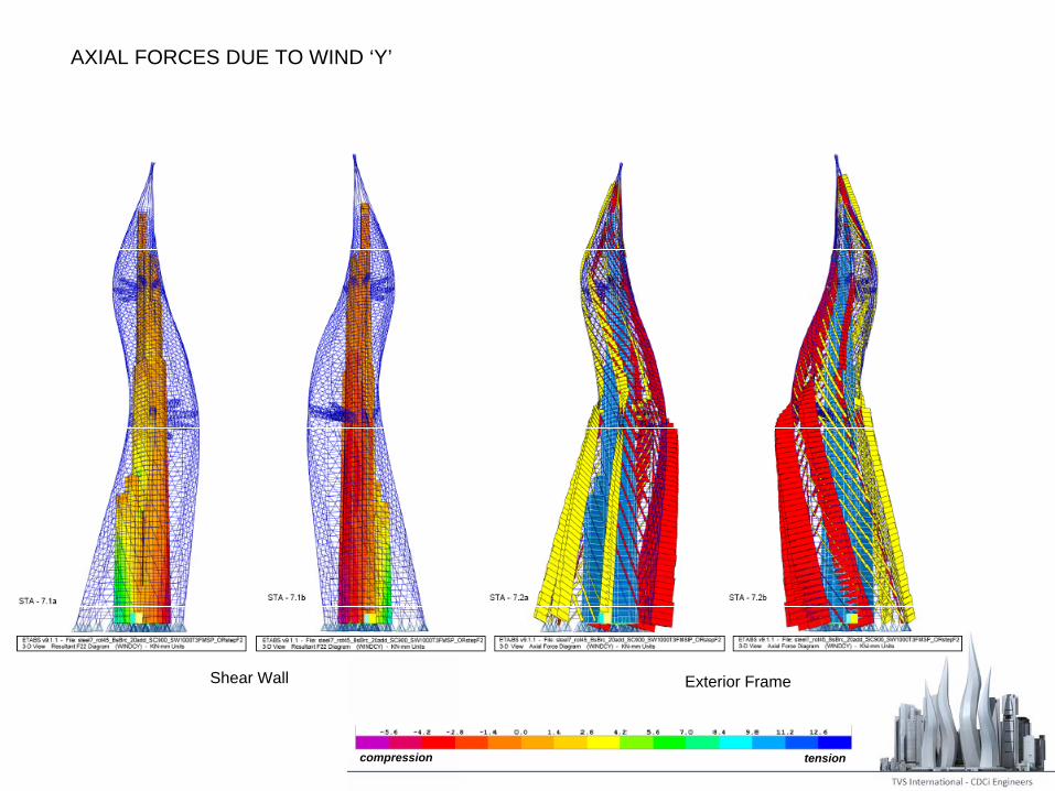
AXIAL FORCES DUE TO WIND ‘Y’
compression tension
Shear Wall Exterior Frame
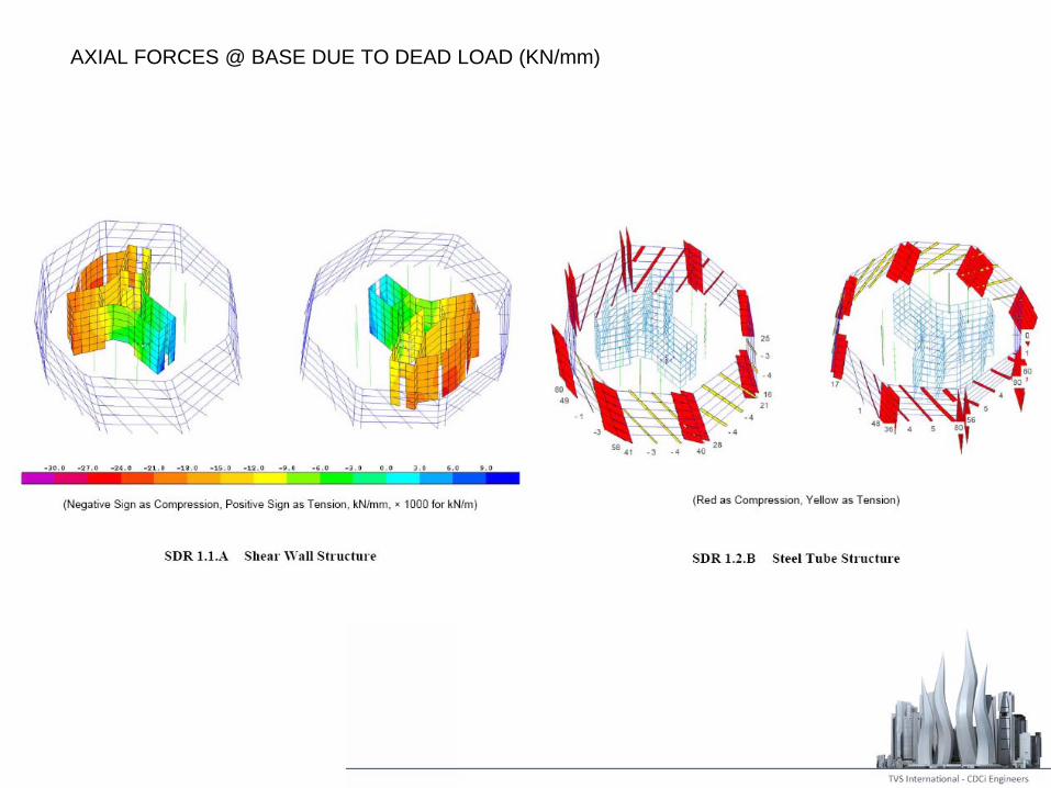
AXIAL FORCES @ BASE DUE TO DEAD LOAD (KN/mm)
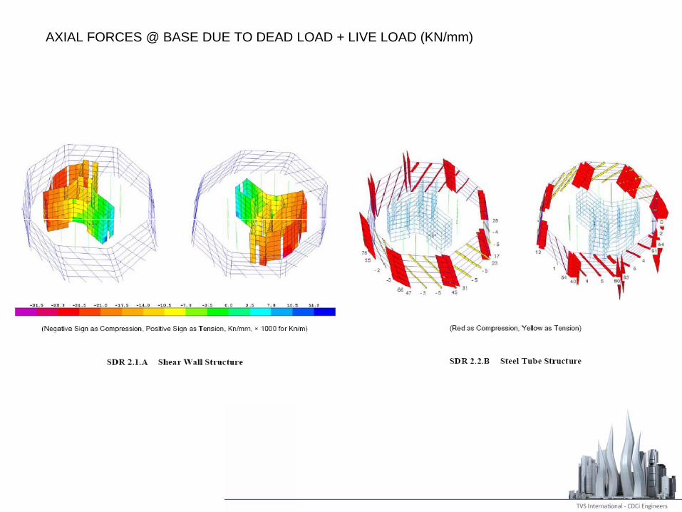
AXIAL FORCES @ BASE DUE TO DEAD LOAD + LIVE LOAD (KN/mm)
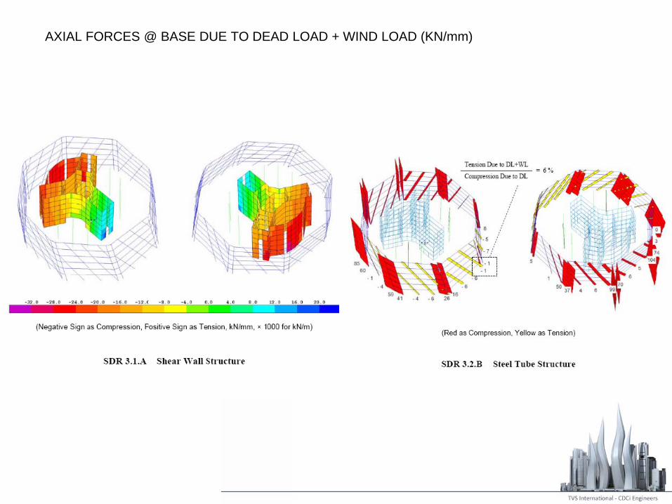
AXIAL FORCES @ BASE DUE TO DEAD LOAD + WIND LOAD (KN/mm)
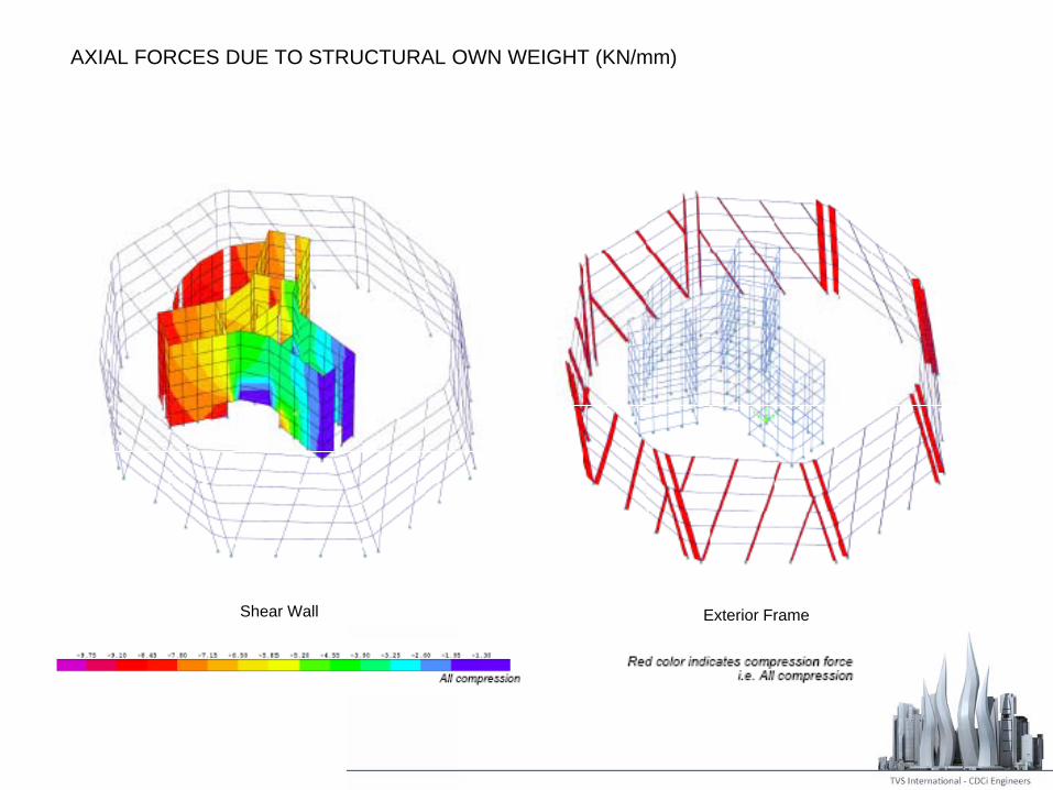
AXIAL FORCES DUE TO STRUCTURAL OWN WEIGHT (KN/mm)
Shear Wall Exterior Frame
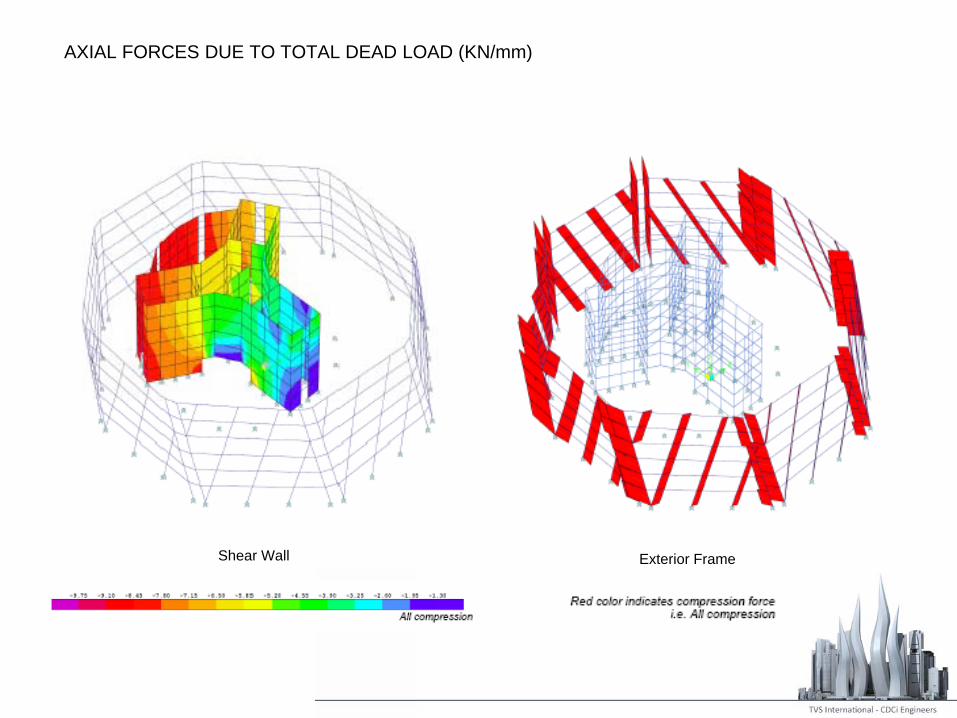
AXIAL FORCES DUE TO TOTAL DEAD LOAD (KN/mm)
Shear Wall Exterior Frame
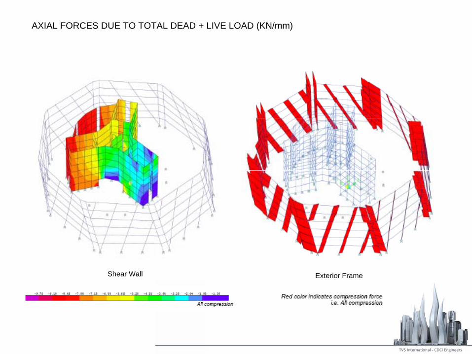
AXIAL FORCES DUE TO TOTAL DEAD + LIVE LOAD (KN/mm)
Shear Wall Exterior Frame

AXIAL FORCES @ BASE OF EXTERIOR FRAME
Due To Dead Load Due to Wind Load
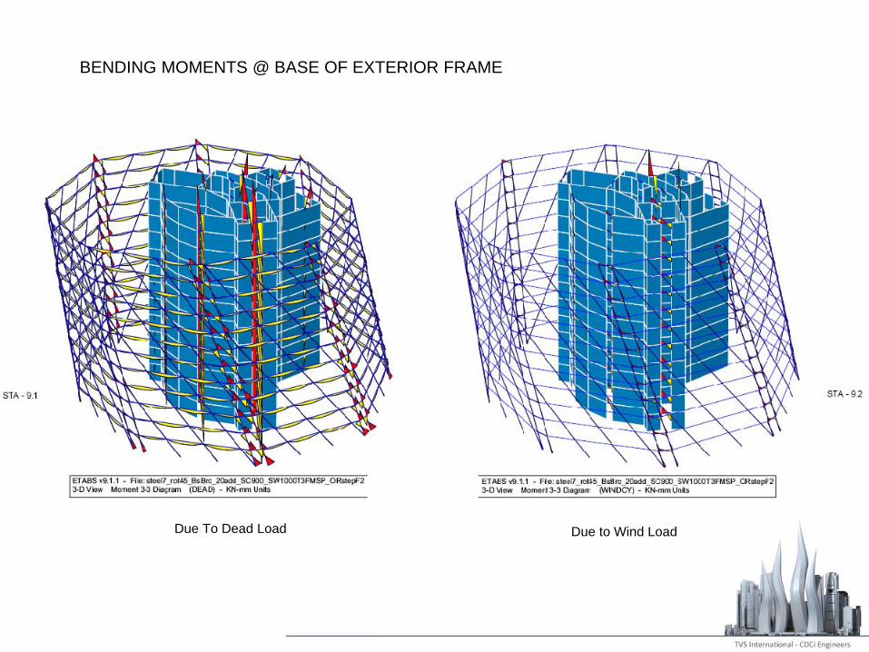
BENDING MOMENTS @ BASE OF EXTERIOR FRAME
Due To Dead Load Due to Wind Load
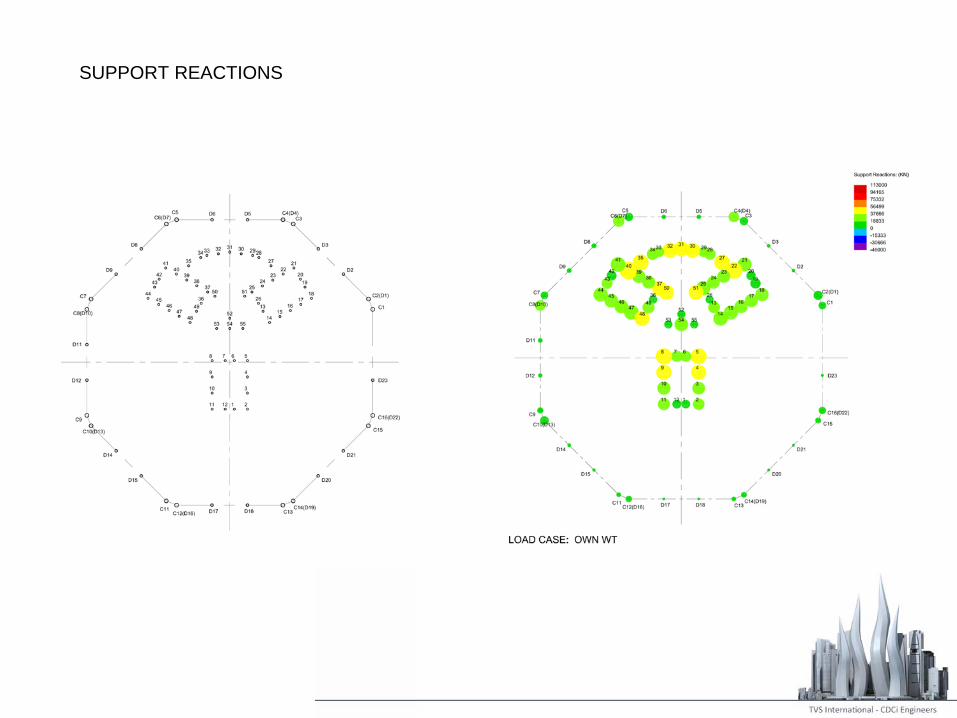
SUPPORT REACTIONS
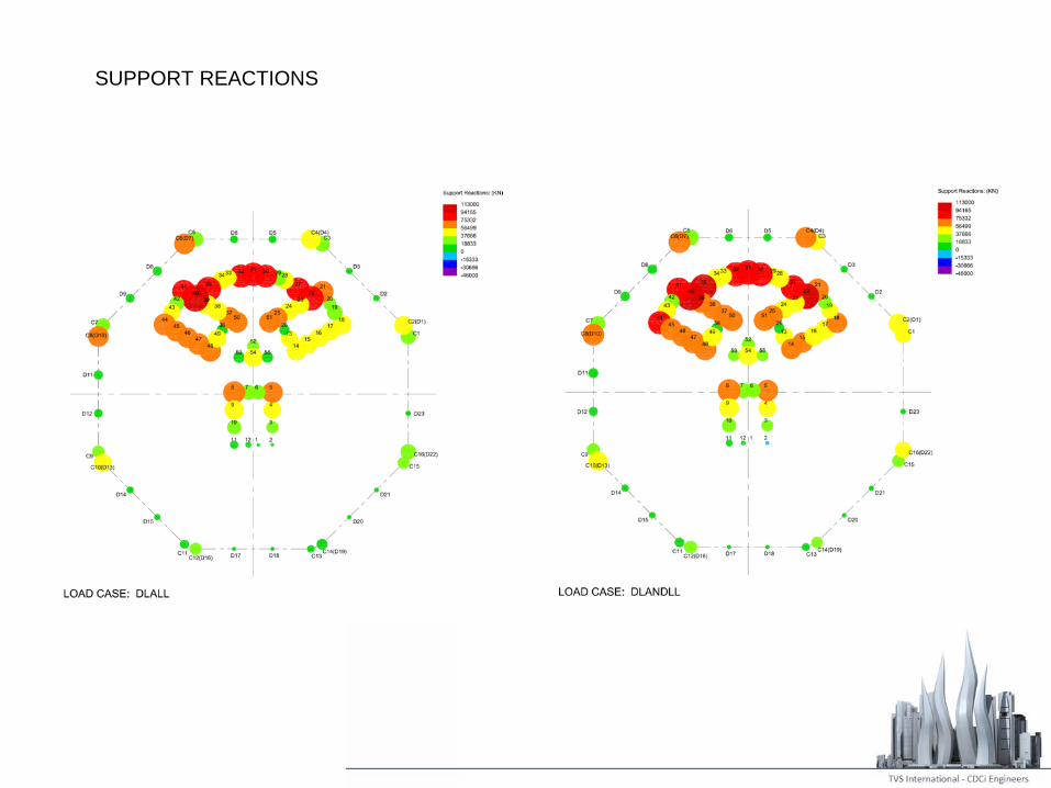
SUPPORT REACTIONS

SUPPORT REACTIONS
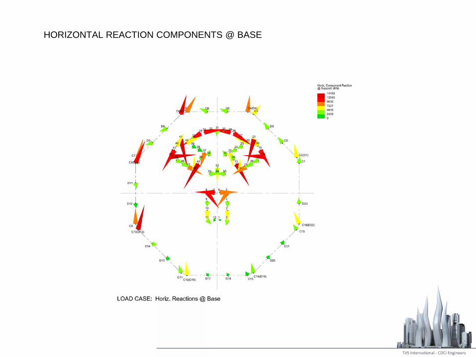
HORIZONTAL REACTION COMPONENTS @ BASE
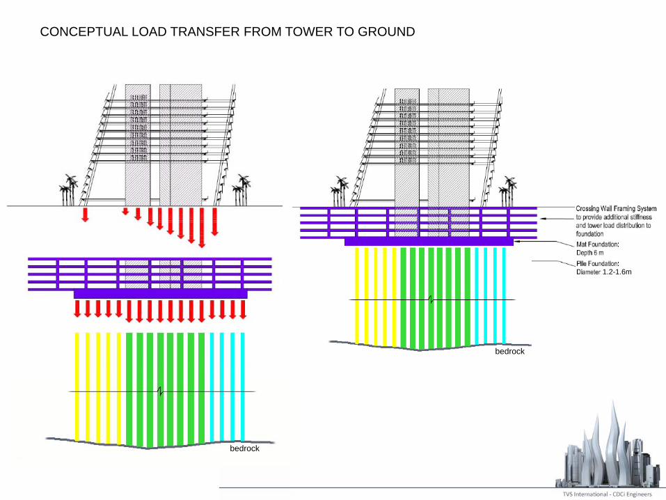
CONCEPTUAL LOAD TRANSFER FROM TOWER TO GROUND
bedrock
bedrock
1.2-1.6m