Structure Analysis of Micro-Milling Machine Construction ...
8
International Journal of Engineering Trends and Technology Volume 69 Issue 1, 205-212, January 2021 ISSN: 2231 – 5381 /doi: 10.14445/22315381/IJETT-V69I1P231 © 2021 Seventh Sense Research Group® This is an open access article under the CC BY-NC-ND license (http://creativecommons.org/licenses/by-nc-nd/4.0/) Structure Analysis of Micro-Milling Machine Construction Frame Design Sarjito 1 , Brandon Lau 2 , Rasidi Ibrahim #2 , Zazuli Mohid 2 1 Faculty of Engineering, Universitas Muhammadiyah Surakarta, Jawa Tengah, Indonesia 2 Faculty of Mechanical and Manufacturing Engineering, Universiti Tun Hussein Onn Malaysia, Parit Raja, 86400, Malaysia # [email protected] Abstract — Extreme precision and accuracy dimension with high quality of surface layer of product produced by the micro-milling machine is very important; hence the Structure of the micro-milling machine should be rigid and sturdy enough to withstand the force acting on the Structure when the machine operates. In this research, the objective is to design the micro-milling machine structure frame and to conduct static structural and modal analysis on the designated structures. Three micro-milling machine structure designs were proposed and compared in terms of the finite element analysis using ANSYS software, and the material used for the structures is Aluminum 7075-T6. The natural frequency and mode shape of the structures were analyzed, and the results are shown for the first mode shape for Structure A amount to 363.97 which is higher than that of Structure B, 278.96 and Structure C, 252.54 . Hence, it can be concluded that Structure A has been chosen as the best design since Structure A has the highest natural frequency among those three structures. Keywords — Design, modal analysis, mode shape, micro- milling machine, static structural analysis I. INTRODUCTION Nowadays, there are a lot of machine structures that had been designed. These machine structures consist of their own characteristics that fulfill the requirements or the needs to function in the best condition [1]. The production of mechanical components with manufactured features in a range of microns is today’s demand for the miniaturization of devices [2,3,4]. The micro-milling machine has static and dynamic behavior of the machine structure that had to be analyzed and developed, and it is important to sustain required accuracy, reliability, and productivity [5,6,7,33,35]. Micro-machining has become increasingly popular in the manufacturing industry. This goes for micro-milling as well [8,9,10,31]. In this research, the existing micro-milling machine that was developed and analyzed by a previous group of researchers needed external support to operate. The machine structure of the existing micro-milling machine needed external support, which indicates that the Structure is no longer rigid enough to withstand the static and dynamic forces acting on it [11,12,13,14]. Therefore, the structure frames of the micro-milling machine are designed. The static and dynamic behavior of the machine structures are analyzed, and the optimum Structure is then chosen as the micro-milling machine structure frame. The objectives of this research are to design the structure frames for the existing micro-milling machine using SolidWorks software, to investigate the Structure A, B, and C for replacing the current micro-milling machine structure frame, and lastly to analyze the designated structure frames of the existing micro-milling machine using ANSYS software. The basic idea of this FEM is actually to find the solution to a complicated structural problem by replacing the problem with a simpler structure [15,16,17,18]. The significance of the study is to be able to design and analyze the structural frame of the micro-milling machine. With the usage of SolidWorks 2018, the structure frames of the machine are able to be designed. The static and dynamic analysis of the Structure is able to be determined with the help of finite element analysis where ANSYS software is used [19,20,21,22]. This can help in analyzing the rigidity of the structure frames, and it will be easier to choose the optimum structure frame for the micro-milling machine [23,24,25,26]. This study can help in comparing designs for the micro- milling machine. Regarding the design of the machine structure, economic and environmental considerations are essential where overdesigned and less optimum performance and reliability are not tolerated. Therefore, this study can fulfill the demands made by the consumer, which are less vibration, lower cost, and high efficiency when operating. Figures 1 and 2 show the existing Micro-Milling Machine.
Transcript of Structure Analysis of Micro-Milling Machine Construction ...

International Journal of Engineering Trends and Technology Volume 69 Issue 1, 205-212, January 2021 ISSN: 2231 – 5381 /doi:10.14445/22315381/IJETT-V69I1P231 © 2021 Seventh Sense Research Group®
This is an open access article under the CC BY-NC-ND license (http://creativecommons.org/licenses/by-nc-nd/4.0/)
Structure Analysis of Micro-Milling Machine
Construction Frame Design
Sarjito 1, Brandon Lau 2, Rasidi Ibrahim #2, Zazuli Mohid2
1 Faculty of Engineering, Universitas Muhammadiyah Surakarta, Jawa Tengah, Indonesia
2 Faculty of Mechanical and Manufacturing Engineering, Universiti
Tun Hussein Onn Malaysia, Parit Raja, 86400, Malaysia # [email protected]
Abstract — Extreme precision and accuracy dimension with
high quality of surface layer of product produced by the
micro-milling machine is very important; hence the
Structure of the micro-milling machine should be rigid and
sturdy enough to withstand the force acting on the Structure
when the machine operates. In this research, the objective is
to design the micro-milling machine structure frame and to conduct static structural and modal analysis on the
designated structures. Three micro-milling machine
structure designs were proposed and compared in terms of
the finite element analysis using ANSYS software, and the
material used for the structures is Aluminum 7075-T6. The
natural frequency and mode shape of the structures were
analyzed, and the results are shown for the first mode shape
for Structure A amount to 363.97 𝐻𝑧 which is higher than
that of Structure B, 278.96 𝐻𝑧 and Structure C, 252.54 𝐻𝑧.
Hence, it can be concluded that Structure A has been chosen as the best design since Structure A has the highest natural
frequency among those three structures.
Keywords — Design, modal analysis, mode shape, micro-
milling machine, static structural analysis
I. INTRODUCTION
Nowadays, there are a lot of machine structures that had
been designed. These machine structures consist of their
own characteristics that fulfill the requirements or the needs
to function in the best condition [1]. The production of mechanical components with manufactured features in a
range of microns is today’s demand for the miniaturization
of devices [2,3,4]. The micro-milling machine has static and
dynamic behavior of the machine structure that had to be
analyzed and developed, and it is important to sustain
required accuracy, reliability, and productivity [5,6,7,33,35].
Micro-machining has become increasingly popular in the
manufacturing industry. This goes for micro-milling as well
[8,9,10,31].
In this research, the existing micro-milling machine that
was developed and analyzed by a previous group of
researchers needed external support to operate. The machine
structure of the existing micro-milling machine needed
external support, which indicates that the Structure is no
longer rigid enough to withstand the static and dynamic
forces acting on it [11,12,13,14].
Therefore, the structure frames of the micro-milling
machine are designed. The static and dynamic behavior of
the machine structures are analyzed, and the optimum
Structure is then chosen as the micro-milling machine
structure frame. The objectives of this research are to design
the structure frames for the existing micro-milling machine
using SolidWorks software, to investigate the Structure A,
B, and C for replacing the current micro-milling machine
structure frame, and lastly to analyze the designated
structure frames of the existing micro-milling machine using ANSYS software. The basic idea of this FEM is actually to
find the solution to a complicated structural problem by
replacing the problem with a simpler structure [15,16,17,18].
The significance of the study is to be able to design and
analyze the structural frame of the micro-milling machine.
With the usage of SolidWorks 2018, the structure frames of the machine are able to be designed. The static and dynamic
analysis of the Structure is able to be determined with the
help of finite element analysis where ANSYS software is
used [19,20,21,22]. This can help in analyzing the rigidity of
the structure frames, and it will be easier to choose the
optimum structure frame for the micro-milling machine
[23,24,25,26].
This study can help in comparing designs for the micro-
milling machine. Regarding the design of the machine
structure, economic and environmental considerations are
essential where overdesigned and less optimum performance
and reliability are not tolerated. Therefore, this study can
fulfill the demands made by the consumer, which are less
vibration, lower cost, and high efficiency when operating.
Figures 1 and 2 show the existing Micro-Milling Machine.
Rasidi Ibrahim et al. / IJETT, 69(1), 205-212, 2021
206
Figure 1: Front view of existing Micro-Milling Machine
Figure 2: Side view of existing Micro-Milling Machine
II. MATERIALS AND METHODS
In order to design and analyze the micro-milling
machine structure, the material for the structure frames is
set, and the steps involved in choosing the suitable Structure
for micro-milling start with designing the Structure followed
by analyzing the Structure then choosing the best design.
The newly designed structures are analyzed and compared
using static structural analysis and modal analysis in
ANSYS software [32,34].
A. Materials
Aluminum 7075-T6 has been chosen as the fixed
material for the designated structure frames. This is because
Aluminum 7075-T6 is said to be used where high strength is
critical and where good corrosion resistance is not important
[27].
B. Methods
The structures are named Structure A, B, and C, which
are shown in Figures 3, 4, and 5. Structure A (i) is based on
the vertical milling machine, whereas Structure B (ii) is
based on the desktop milling machine, and lastly, Structure
C (iii) is based on a bridge-type milling machine. The
conceptual design of all the structures is the base of the
Structure is set to 500 𝑚𝑚 × 500 𝑚𝑚. The volume of the
models are set to 0.0216 𝑚3 each so that the design of the
Structure can be compared. The meshing of the structures
are set to 2 × 10⁻² 𝑚 of its element size and the node shape
is set to tetrahedron shape.
Figure 3: Structure A
Figure 4: Structure B
Figure 5: Structure C
The shapes for all three structures can be differentiated
by the size of the wall or arm of the structures. Structure A uses a single arm to support the spindle, whereas Structure B
uses a wall. However, Structure C uses two arms to support
the spindle and the wall that will use to connect the spindle
onto the Structure.
For static structural analysis, there are three (3) types of
analyses, which are without force, standard earth gravity,
and with force, 50 N and 100 N. When analyzing all of the
three (3) designated structures, there are two (2) boundaries
that are very crucial for the static structural analysis. The
types of the boundary are the fixed support of the Structure
and the presence of the standard earth gravity on the
Structure. Figure 6 shows the fixed support, whereas Figure
7 shows the standard earth gravity.
X-Y
Plane
Structure
Frame
(Base)
Z-axis
Structure
Frame
(Wall)
Spindle
Slide Way and
Fixture
Needed
external
support
indicates that the
rigidity
of the
original
structure
is low.

Rasidi Ibrahim et al. / IJETT, 69(1), 205-212, 2021
207
Figure 6: Fixed support for static structural analysis
Figure 7: Standard earth gravity
First of all, for the fixed support, since the structural
frame of the micro-milling machine would be stationary, it is
certain that the Structure would have fixed support at the
bottom surface of the Structure. Other than that, the
boundary that is set for the Structure is the standard earth
gravity. This is because when the Structure is manufactured,
the Structure will experience gravitational earth pull even
when the machine is not operating. The value of the standard
earth gravity is 9.8066 𝑚 𝑠2⁄ And the direction the
gravitational pull acting on the structures is at negative y-
axis direction.
In order to determine the rigidity of the three (3)
designated models, 50 N and 100 N of forces are applied at
negative X, Y, and Z-axis directions. 50 N and 100 N of
forces are applied separately in order to measure the
deformation of the structures when the force is acting on the
structure increases. The force is applied in 3 different
directions. Figures 8, 9, and 10 show 50 N of force acting on
the arm of the Structure at the negative x-axis, y-axis, and z-axis direction, respectively.
Figure 8: 50 N of force acting on the arm of the Structure
at the negative x-axis
Figure 9: 50 N of force acting on the arm of the Structure
at the negative y-axis
Figure 10: 50 N of force acting on the arm of the
Structure at negative z-axis
For modal analysis, only theoretical modal analysis is
carried out in this study. There is only one boundary
condition for the modal analysis, which is the fixed support.
The fixed support is set at the bottom surface of the
Structure because after the structure frame is manufactured,
the base will be fixed onto the table.
III. RESULTS AND DISCUSSION
The designated structures are analyzed and compared in
order to select the best Structure for the current micro-
milling machine. The analyses involved are static structural
analysis and modal analysis. These analyses are suitable for
analyzing the rigidity of the Structure, especially for the
machine frame.
For static structural analysis, the analysis without force
and with force, 50 N and 100 N are carried out. The graphs
below show the results of total deformation for static
structural analysis.
Figure 11: Graph for negative x-axis direction
5.29E-088.21E-07
1.61E-06
4.92E-08
9.93E-07
1.95E-06
4.55E-07
1.92E-06
3.40E-06
0.00E+00
5.00E-07
1.00E-06
1.50E-06
2.00E-06
2.50E-06
3.00E-06
3.50E-06
4.00E-06
0 50 100
Maxi
mu
m
To
tal D
efo
rmta
ion
(m)
Force (N)
Maximum Total Deformation when Force Acting at
Negative
X-axis Direction
Structure A Structure B Structure C
Fixed
Support
Standard
Earth
Gravity
50 N
Rasidi Ibrahim et al. / IJETT, 69(1), 205-212, 2021
208
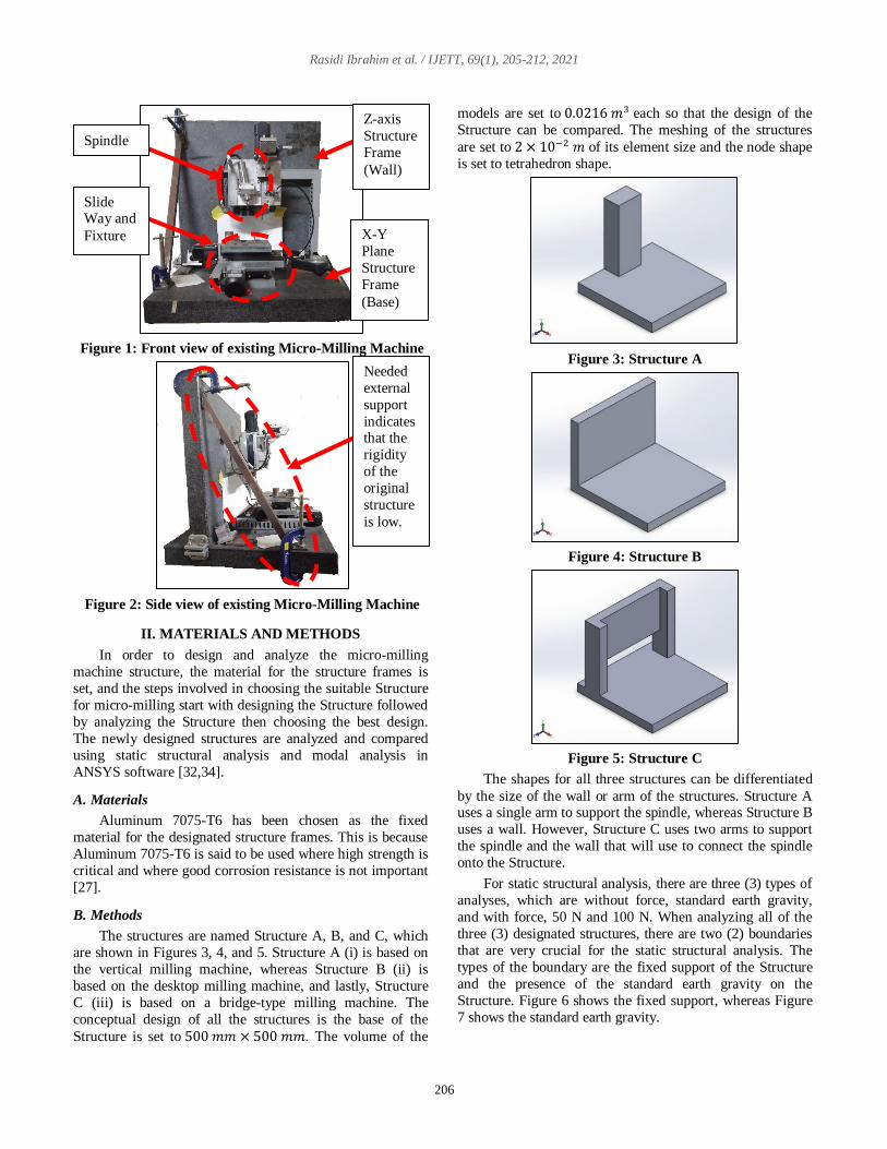
Figure 12: Graph for negative y-axis direction
Figure 13: Graph for negative z-axis direction
The results show that Structure C deformed the most.
This means that Structure A and B are more reliable than
Structure C when there are forces acting on the Structure at a
negative x-axis direction. The smaller the total deformation
formed by the Structure, the more reliable the Structure is
when operating the machine [28,29].
From the graph above, the maximum total deformation
for Structure A and B are relatively lower than that of
Structure C. Structure C shows very large differences
compared to other structures. The differences of the
deformation when only subjected to the gravitational force
between Structure C, the highest displacement of the Structure and Structure B, which has the lowest
displacement is 4.05597 × 10⁻⁷ 𝑚. For 100 N force when
applied to the Structure, the differences between the highest,
Structure C and the lowest deformation, Structure A, is
1.7893 × 10⁻⁸ 𝑚. This means that Structure A and B are
more reliable than Structure C when there are forces acting
on the Structure at a negative x-axis direction. According to
Nyein Chan et al. (2019), the smaller the total deformation
formed by the Structure, the more reliable the Structure is
when operating the machine [29].
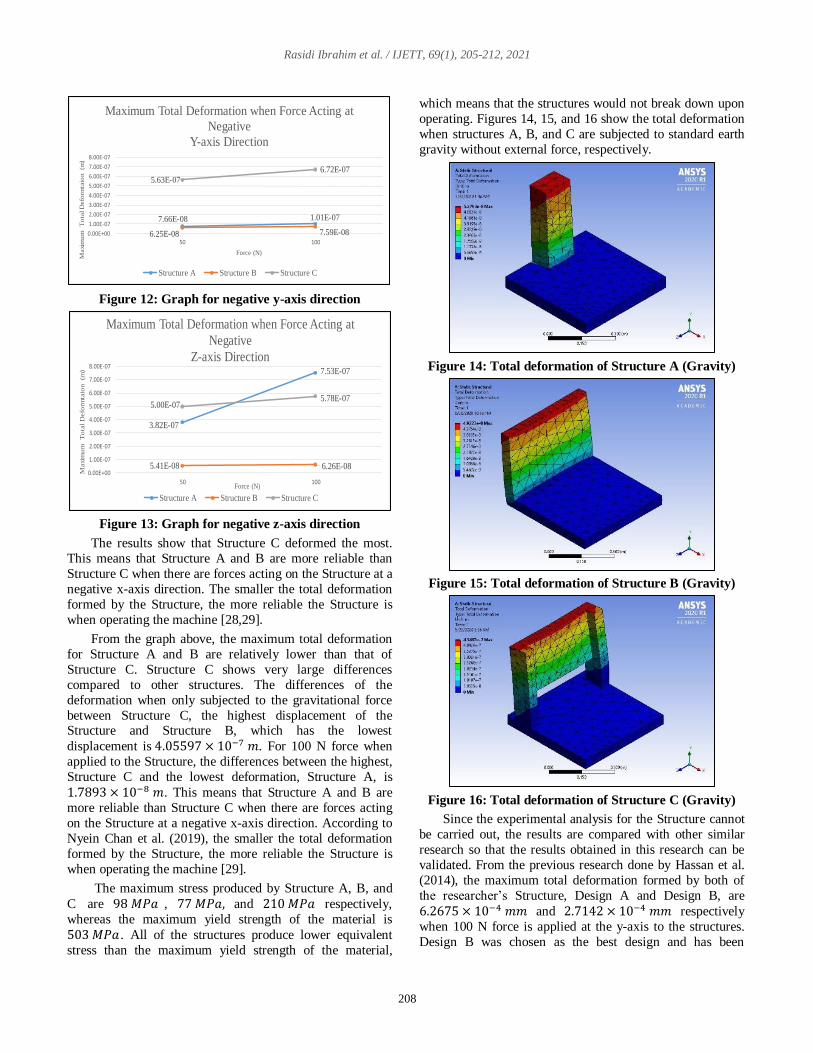
The maximum stress produced by Structure A, B, and
C are 98 𝑀𝑃𝑎 , 77 𝑀𝑃𝑎, and 210 𝑀𝑃𝑎 respectively,
whereas the maximum yield strength of the material is
503 𝑀𝑃𝑎 . All of the structures produce lower equivalent
stress than the maximum yield strength of the material,
which means that the structures would not break down upon
operating. Figures 14, 15, and 16 show the total deformation
when structures A, B, and C are subjected to standard earth
gravity without external force, respectively.
Figure 14: Total deformation of Structure A (Gravity)
Figure 15: Total deformation of Structure B (Gravity)
Figure 16: Total deformation of Structure C (Gravity)
Since the experimental analysis for the Structure cannot
be carried out, the results are compared with other similar
research so that the results obtained in this research can be
validated. From the previous research done by Hassan et al.
(2014), the maximum total deformation formed by both of
the researcher’s Structure, Design A and Design B, are
6.2675 × 10⁻⁴ 𝑚𝑚 and 2.7142 × 10⁻⁴ 𝑚𝑚 respectively
when 100 N force is applied at the y-axis to the structures.
Design B was chosen as the best design and has been
7.66E-08 1.01E-07
6.25E-08 7.59E-08
5.63E-07
6.72E-07
0.00E+00
1.00E-07
2.00E-07
3.00E-07
4.00E-07
5.00E-07
6.00E-07
7.00E-07
8.00E-07
50 100
Maxi
mu
m
To
tal D
efo
rmta
ion
(m)
Force (N)
Maximum Total Deformation when Force Acting at
Negative
Y-axis Direction
Structure A Structure B Structure C
3.82E-07
7.53E-07
5.41E-08 6.26E-08
5.00E-075.78E-07
0.00E+00
1.00E-07
2.00E-07
3.00E-07
4.00E-07
5.00E-07
6.00E-07
7.00E-07
8.00E-07
50 100
Maxi
mu
m
To
tal D
efo
rmta
ion
(m
)
Force (N)
Maximum Total Deformation when Force Acting at
Negative
Z-axis Direction
Structure A Structure B Structure C

Rasidi Ibrahim et al. / IJETT, 69(1), 205-212, 2021
209
already validated with the modal analysis, which means that
the deformation formed by the Structure is acceptable.
In this thesis, the y-axis direction of the force is at the x-
axis direction, which means that the results that will be
compared is when the force of 100 N is applied at the x-axis
direction. The first Structure, Structure A, shows 1.6096 ×10⁻⁴ 𝑚𝑚 whereas Structure B, 1.9472 × 10⁻⁴ 𝑚𝑚 and
lastly Structure C, 3.3989 × 10⁻⁴ 𝑚𝑚. All of the values for
the displacement of the structures at the x-axis direction are
±0.0001 𝑚𝑚 of the previous journal chosen design.
The mode shape and the total deformation of Structure
A, B, and C are analyzed. Figure 17 shows the mode shape
1, 2, 3, and 4 of Structure A. Figure 18 shows the mode
shape 1, 2, 3, and 4 of Structure B, whereas Figure 19 shows the mode shape 1, 2, 3, and 4 of Structure C.
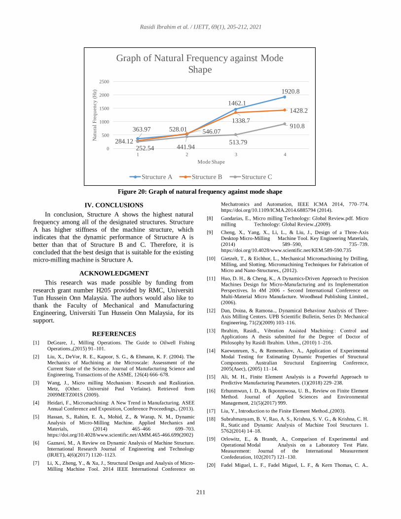
The graphs in Figure 20 shows the graph for the natural
frequency of all the structures. The results show that the
natural frequency for Structure A is higher than that of
Structure B and Structure C. For mode shapes 1, 3, and 4,
Structure A shows a higher natural frequency than that of
Structure B, whereas only in mode shape 2 that Structure B show a slightly higher natural frequency, and lastly,
Structure C shows none. The minimum natural frequency of
the structure is based on the mode shape 1 of the Structure.
This means that Structure A has a higher natural frequency
than Structure B, which is 79.85 𝐻𝑧 more and when
compared with Structure C is 111.43 𝐻𝑧. The results show
that Structure A has higher stiffness of the machine
structure, which indicates that the dynamic performance of
Structure A is better than that of Structure B and Structure C
[7,5,30].
Figure 17: Mode shape of Structure A
Bending
front to back
Bending side
to side
Twisting at
y-axis
Twisting at
z-axis
(d) Mode Shape 4
(a) Mode Shape 1 (b) Mode Shape 2
(c) Mode Shape 3

Rasidi Ibrahim et al. / IJETT, 69(1), 205-212, 2021
210
Figure 18: Mode shape of Structure B
Figure 19: Mode shape of Structure C
(d) Mode Shape 4
(a) Mode Shape 1 (b) Mode Shape 2
(c) Mode Shape 3
Twisting at
y-axis
Bending
front to back
Twisting at 2
position at y-
axis
Bending side
to side
(d) Mode Shape 4
(a) Mode Shape 1 (b) Mode Shape 2
(c) Mode Shape 3
Bending
front to
back
Twisting at
y-axis
Bending
at both
side of the
wall
Bending side
to side with
twisting at y-
axis
Rasidi Ibrahim et al. / IJETT, 69(1), 205-212, 2021
211
Figure 20: Graph of natural frequency against mode shape
IV. CONCLUSIONS
In conclusion, Structure A shows the highest natural
frequency among all of the designated structures. Structure
A has higher stiffness of the machine structure, which
indicates that the dynamic performance of Structure A is
better than that of Structure B and C. Therefore, it is
concluded that the best design that is suitable for the existing
micro-milling machine is Structure A.
ACKNOWLEDGMENT
This research was made possible by funding from
research grant number H205 provided by RMC, Universiti
Tun Hussein Onn Malaysia. The authors would also like to
thank the Faculty of Mechanical and Manufacturing Engineering, Universiti Tun Hussein Onn Malaysia, for its
support.
REFERENCES
[1] DeGeare, J., Milling Operations. The Guide to Oilwell Fishing
Operations.,(2015) 91–101.
[2] Liu, X., DeVor, R. E., Kapoor, S. G., & Ehmann, K. F. (2004). The
Mechanics of Machining at the Microscale: Assessment of the
Current State of the Science. Journal of Manufacturing Science and
Engineering, Transactions of the ASME, 126(4) 666–678.
[3] Wang, J., Micro milling Mechanism : Research and Realization.
Metz, (Other. Université Paul Verlaine). Retrieved from
2009METZ001S (2009).
[4] Heidari, F., Micromachining: A New Trend in Manufacturing. ASEE
Annual Conference and Exposition, Conference Proceedings., (2013).
[5] Hassan, S., Rahim, E. A., Mohid, Z., & Warap, N. M., Dynamic
Analysis of Micro-Milling Machine. Applied Mechanics and
Materials, (2014) 465–466 699–703.
https://doi.org/10.4028/www.scientific.net/AMM.465-466.699(2002)
[6] Gaznavi, M., A Review on Dynamic Analysis of Machine Structure.
International Research Journal of Engineering and Technology
(IRJET), 4(6)(2017) 1120–1123.
[7] Li, X., Zheng, Y., & Xu, J., Structural Design and Analysis of Micro-
Milling Machine Tool. 2014 IEEE International Conference on
Mechatronics and Automation, IEEE ICMA 2014, 770–774.
https://doi.org/10.1109/ICMA.2014.6885794 (2014).
[8] Gandarias, E., Micro milling Technology: Global Review.pdf. Micro
milling Technology: Global Review.,(2009).
[9] Cheng, X., Yang, X., Li, L., & Liu, J., Design of a Three-Axis
Desktop Micro-Milling Machine Tool. Key Engineering Materials,
(2014) 589–590, 735–739.
https://doi.org/10.4028/www.scientific.net/KEM.589-590.735
[10] Gietzelt, T., & Eichhor, L., Mechanical Micromachining by Drilling,
Milling, and Slotting. Micromachining Techniques for Fabrication of
Micro and Nano-Structures., (2012).
[11] Huo, D. H., & Cheng, K., A Dynamics-Driven Approach to Precision
Machines Design for Micro-Manufacturing and its Implementation
Perspectives. In 4M 2006 - Second International Conference on
Multi-Material Micro Manufacture. Woodhead Publishing Limited.,
(2006).
[12] Dan, Doina, & Ramona.., Dynamical Behaviour Analysis of Three-
Axis Milling Centers. UPB Scientific Bulletin, Series D: Mechanical
Engineering, 71(2)(2009) 103–116.
[13] Ibrahim, Rasidi., Vibration Assisted Machining : Control and
Applications A thesis submitted for the Degree of Doctor of
Philosophy by Rasidi Ibrahim. Uthm., (2010) 1–216.
[14] Kaewunruen, S., & Remennikov, A., Application of Experimental
Modal Testing for Estimating Dynamic Properties of Structural
Components. Australian Structural Engineering Conference,
2005(Asec), (2005) 11–14.
[15] Ali, M. H., Finite Element Analysis is a Powerful Approach to
Predictive Manufacturing Parameters. (1)(2018) 229–238.
[16] Erhunmwun, I. D., & Ikponmwosa, U. B., Review on Finite Element
Method. Journal of Applied Sciences and Environmental
Management, 21(5)(2017) 999.
[17] Liu, Y., Introduction to the Finite Element Method.,(2003).
[18] Subrahmanyam, B. V, Rao, A. S., Krishna, S. V. G., & Krishna, C. H.
R., Static and Dynamic Analysis of Machine Tool Structures 1.
5762(2014) 14–18.
[19] Orlowitz, E., & Brandt, A., Comparison of Experimental and
Operational Modal Analysis on a Laboratory Test Plate.
Measurement: Journal of the International Measurement
Confederation, 102(2017) 121–130.
[20] Fadel Miguel, L. F., Fadel Miguel, L. F., & Kern Thomas, C. A..
363.97 528.01
1462.1
1920.8
284.12
546.07
1338.7
1428.2
252.54 441.94513.79
910.8
0
500
1000
1500
2000
2500
1 2 3 4
Natu
ral
Fre
qu
en
cy
(H
z)
Mode Shape
Graph of Natural Frequency against Mode
Shape
Structure A Structure B Structure C

Rasidi Ibrahim et al. / IJETT, 69(1), 205-212, 2021
212
Theoretical and Experimental Modal Analysis of a Cantilever Steel
Beam with a Tip Mass. Proceedings of the Institution of Mechanical
Engineers, Part C: Journal of Mechanical Engineering Science,
223(7)(2009) 1535–1541.
[21] Azoury, C., Experimental and Analytical Modal Analysis of a
Crankshaft. IOSR Journal of Engineering, 02(04)(2012) 674–684.
[22] Bernal, M., Urban, M. W., Nenadic, I., & Greenleaf, J. F., Modal
Analysis of Ultrasound Radiation Force Generated Shear Waves on
Arteries. 2010 Annual International Conference of the IEEE
Engineering in Medicine and Biology Society, EMBC., 10(2010)
2585–2588.
[23] Patwari, A. U., Faris, W. F., Nurul Amin, A. K. M., & Loh, S. K.
(2009). Dynamic Modal Analysis of Vertical Machining Centre
Components. Advances in Acoustics and Vibration, (2009) (2015), 1–
10.
[24] Visser, W., & Brundtland, G. H.., Our Common Future (The
Brundtland Report): World Commission on Environment and
Development. The Top 50 Sustainability Books, (2013) 52–55.
[25] Ibrahim, R., Bateman, R., Cheng, K., Wang, C., & Au, J., Design and
Analysis of a Desktop Micro-Machine for Vibration-Assisted
Micromachining. Proceedings of the Institution of Mechanical
Engineers, Part B: Journal of Engineering Manufacture, 225(8)
(2011) 1377–1391. https://doi.org/10.1177/2041297510393625
[26] Pakzad, S., Rajab, A. K. S., Mahboubkhah, M., Ettefagh, M. M., &
Masoudi, O., Modal Analysis of the Milling Machine Structure
through FEM and Experimental Test. Advanced Materials Research,
566 (2012) 353–356.
[27] Gándara, M. J. F., Aluminium: The Metal of Choice. Materiali in
Tehnologije, 47(3)(2013) 261–265.
[28] Honkalas, R. R., Kulkarni, M. L., & Deshmukh, B. B., Static,
Dynamic, and Modal Analysis of Micromilling Table. IOSR Journal
of Mechanical and Civil Engineering, 11(3)(2014) 22–28.
https://doi.org/10.9790/1684-11362228
[29] Nyein Chan, Than Zaw Oo, Aung Myo San Hlaing., Design and
Structural Analysis of 3 Axis CNC Milling Machine Table.
International Journal of Trend in Scientific Research and
Development, 3(6) 943–948. Retrieved from
https://www.ijtsrd.com/papers/ijtsrd29197.pdf%0Ahttps://www.ijtsrd.
com/engineering/mechanical-engineering/29197/design-and-
structural-analysis-of-3-axis-cnc-milling-machine-table/nyein-chan.
[30] Chen, T. C., Chen, Y. J., Hung, M. H., & Hung, J. P., Design
Analysis of Machine Tool Structure with Artificial Granite Material.
Advances in Mechanical Engineering, 8(7)(2016) 1–14.
https://doi.org/10.1177/1687814016656533
[31] Ibrahim, M. R., Rahim, Z., Rahim, E., Tobi, L., Cheng, K., & Ding,
H. (2017). An Experimental Investigation of Cutting Temperature and
Tool Wear in 2 Dimensional Ultrasonic Vibrations Assisted
Micro-Milling. MATEC Web of Conferences, 95,
https://doi.org/10.1051/matecconf/20179507005
[32] Ibrahim, R., Rafai, N. H., Rahim, E. A., Cheng, K., & Ding, H., A
Performance of 2 Dimensional Ultrasonic Vibration Assisted Milling
in Cutting Force Reduction, on Aluminium AL6061. ARPN Journal
of Engineering and Applied Sciences, 11(18)(2016) 11124–11128.
[33] Li, H., Ibrahim, R., & Cheng, K. (2011). Design and Principles of an
Innovative Compliant Fast Tool Servo for Precision Engineering.
Mechanical Sciences, 2(2)(2011) 139–146.
https://doi.org/10.5194/ms-2-139-2011
[34] Rachmat, H., Mulyana, T., Hasan, S. B. H., & Ibrahim, M.
R.,. Design Selection of in-UVAT using MATLAB Fuzzy Logic
Toolbox. https://doi:10.1007/978-3-319-51281-5_54 (2017).
[35] Kamdani, K., Rafai, N. H., Ibrahim, R., Ahmad, S., Rahim, M. Z.,
Yee Long, C., Mulyana, T., Experimental Study on the Degree of
Surface Generation by Edge Preparation Tools and Propose
Optimization Approach. H205, (2020).