
STRUCTURALDESIGNCRITERIA APPLICABLETOA SPACESHUTTLE
104
NASA SPACEVEHICLE DESIGNCRITERIA (STRUCTURES) NASA SP-8057 STRUCTURAL DESIGNCRITERIA APPLICABLE TO A SPACESHUTTLE cAs _ F_ L_ Op_ _ JANUARY 1971 REVISED MARCH 1972 NATIONAL AERONAUTICS AND SPACE ADMINISTRATION 4: •
Transcript of STRUCTURALDESIGNCRITERIA APPLICABLETOA SPACESHUTTLE

NASASPACEVEHICLEDESIGNCRITERIA(STRUCTURES)
NASA SP-8057
STRUCTURALDESIGNCRITERIAAPPLICABLETO A SPACESHUTTLE
cAs _ F_L_Op_ _
JANUARY 1971REVISED
MARCH 1972
NATIONAL AERONAUTICS AND SPACE ADMINISTRATION
4: •

PREFACE
In 1969, when planning for the development of a
manned space-shuttle vehicle began, it was evident that
significant advances in structural design would be neededto combine a manned recoverable booster and a reusable
orbital vehicle with conventional flight snd landing
capabilities. Accordingly, new structural design criteria
would be requ red for use in the vehicle development
program to obtain a flightworthy structure (i.e., a
structure possessing sufficient strength and stiffness and
al other physical, mechanical, and functional charac-
teristics required to accomplish each vehicle mission
without jeopardizing mission objectives).
Ear y in 1970, the National Aeronautics and Space
Administration initiated a program to prepare structural
design criteria appdcable to a manned space-snuttlevehicle. With the aid of an industry-Government team
formed of representatives of major aerospace companies,
most NASA Centers, NASA Headquarters, and the
USAF, the criteria were first published in January 1971.
Since then, mree developmems have occurred which
created a need to revise the document. First, the
space-shuttle concept changed in the ensuing time The
current NASA concept is a reusable orbital vehicle
mounted on an expendable liquid-Drooellan[ lanK with
two recoverable solid-rocKet motors used to assist ir
boosting tne vehicle. Second, oroolem areas n structurs
design criteria for the space shuttle which were identified
n the course of the initia effort nave been resolved.
And third, considerable progress nas been achieved in
shuttle-related design technology. This updated docu-
ment reflects all three developments.
The structural criteria presented in this document are
limited to general and mission-oriented criteria and are
not configuration specific. Care has been taken to ensure
that the criteria will not restrict configuration develop-
ment and will not estab ish the overall risk level. In some
instances, margins of confidence are indicated, not only
because expenence has shown them to be necessary out
also because technology now permits quantitative values
to be established.
The criteria and interpretative information presented
herein do not represent structural requirements, struc-
tural specifications, or any type of contractual docu-
ment, but rather are intended to assist in the preparation
of such documents.
This document was revised by an industry-Government
team similar to the group which prepared the initial
edition Meetings of industry, NASA, and liaison parti-
cipams were held at Langley Research Center to review
industry critiaues of the original document and to
coordinate changes in me text. The activity was
managed and the document was edited by the Langley
Structural Systems Oi:[ice.
The following organizations and individuals participated
in the development of the original document and/or its
revision:
BELL AEROSPACE COMPANY
Wilfred H. Dukes (Industry Chairman)
GENERAL DYNAMICS CORPORAT ON
Michael Dublin**
Raymond Schuett
GRUMMAN AEROSPACE CORPORATION
W_rner Lansing
Andrew Shreeves**
LOCKHEED AIRCRAFT CORPORATION
T. J. Harvey
A. E. Trapp**
_*Contributor to both the original document and its
revision.

• i _
MARTIN MARl ETTA CORPORATI ON
Robert J. Heymans
Allan M. Norton
James L. Parham*
Donald J. Trent
McDONNELL DOUGLAS CORPORATION
H. P. Adam*
T. P. Brooks
Roy H. Christensen**
L. W. Davidson (Literary Editor)
Marilyn B. Harmon**
James Shepherd**
F. R. Smith** (Chief Editor)
Esther A. Spachner (Literary Editor)**
NORTH AMER ICAN ROCKWELL CORPORATION
Len A. Harris
Harvey J. Hoge
Richard Schleicher
R. F. Stevenson
R. Westrup*
THE AEROSPACE CORPORATION
N. N. Au*
K. G. Graff
THE BOEING COMPANY
S. I. Gravitz
William L. GrayHarold J. Runstad
D. K. Zimmerman*
TRW Inc.
H. L. Sujata
AIR FORCE FLIGHT DYNAMICS LABORATORY
Frank D. Boensch
KENNEDY SPACE CENTER, NASA
H. C. Shoaf
LANGLEY RESEARCH CENTER, NASA
A. L. Braslow (NASA Cochairman)
J. P. Dickson, Jr.
Philip Donely
J. R. Hall (NASA Cochairman)**
D. H. Humes*
R. L. Jackson*
G. W. Jones, Jr.*
E. T. Kruszewski*
S. A. Leadbetter*
R. W. Leonard**
C. C. Poe, Jr.*
W. H. Reed*
E. D. Schult
W. C. Thornton*
L. F. Vosteen
E. S, Wolff*
LEWIS RESEARCH CENTER, NASA
M. J. MacKinnon
MANNED SPACECRAFT CENTER, NASA
L. G. St. Leger
MARSHALL SPACE FLIGHT CENTER, NASA
Charles E. Lifer
OFFICE OF AERONAUTICS AND SPACE
TECHNOLOGY, NASA
Thomas V. Cooney
William Underwood
OFFICE OF MANNED SPACE FLIGHT, NASAKenneth L. Turner
*Contributor to the revised document.
**Contributor to both the original document and its
revision.
For sale by the National Technical Information Service
Springfield, Virginia 22151 Price $3.00

CONTENTS
",j
?
1. INTRODUCTION 1-1 4.4.2.2
4.4.2.3
1.1 PURPOSE
1.2 SCOPE
1.3 APPROACH
1.4 PRECEDENCE.
1.5 DEFINITIONS
1-1
1-1 4.4.31-1
1-14.4.3.1
1-14.4.3.2
2. RELATED DOCUMENTS 2-1 4.5
3. DESIGN OBJECTIVES 3-1
3.1
3.2
3.3
3.4
3.5
3.5.1
3.5.2
3.5.3
3.5.4
3.6
WEIGHT 3-1
COST 3-1
SIMPLICITY 3-1
MANUFACTURABI LITY 3-1
MAINTAINABILITY 3-1
ACCESSI BI LITY 3-1
INTERCHANGEABI LITY _ 3-1
TANK SERVICEABI LITY 3-1
REPAIR AND REFURBISHMENT-- 3-2
COMPATI BI LI TY 3-2
4. DESIGN CHARACTERISTICS 4-1
4.1 DESIGN FACTORS 4-1
4.2 MARGIN OF SAFETY 4-3
4.3 STATIC ELASTICITY 4-3
4.3.1 DIVERGENCE 4-3
4.3.2 CONTROL-SURFACE 4-3
EFFECTIVENESS 4-3
4.3.3
4.4
4.4.1
4.4.1.1
4.4.1.2
4.4.1.3
4.4.1.4
4.4.2
4.4.2.1
BUCKLING AND CRIPPLING 4-3
DYNAMIC ELASTICITY - 4-4
DYNAMIC AEROELASTIC
I NSTABI L TIES ,4-4
Classical Flutter. 4-4
Stall Flutter 4-4
Panel Flutter 4-4
Control-Surface Buzz 4-5
DYNAMIC COUPLING 4-5
Flight-Control System and Elastic
Modes 4-5
4.6
4.6.1
4.6.2
4.6.2.1
4.6.2.2
4.6.3
4.6.3.1
4.6.3.2
4.6.3.3
4.6.3.4
4.6.3.5
4.6.3.6
4.6.3.7
4.6.3.8
4.6.3.9
4.6.3.10
4.7
4.7.1
4.7.2
4.7.3
4.7.4
4.7.5
4.7.6
4.7.7
4.8.1.1
Slosh 4-5
Structure and Propulsion System
(Pogo) 4-6
DYNAMICALLY INDUCED
ENVIRONMENTS 4-6
Noise, Vibration, and Shock .4-6
Buffeting 4-6
THERMAL PROTECTION
SYSTEM CHARACTERISTICS-- 4-7
MATERIAL CHARACTERISTICS 4-8
PHYSICAL PROPERTIES .4-8
ALLOWABLE MECHANICAL
PROPERTI ES 4-8
Structural Component Allowables 4-8
Full-Scale Assembly Allowables 4-8
FAI LURE MECHANISMS 4-8
Fatigue 4-8Brittle Fracture _ 4-9
Stress-Corrosion Cracking 4-9
Hydrogen Embrittlement 4-9
Temper Embrittlement 4-10
Creep .- 4-10
General (Pitting-Type) Corrosion 4-10
Galvanic Corrosion - 4-10
Meteoroid-Impact Damage 4-10
Radiation Damage 4-10
SERVICE LIFE 4-10
SAFE-LIFE 4-10
FAI L-SAFE .4-1 1
MATERIAL PROPERTI ES .4-1 1
LOAD SPECTRA 4-1 1
CYCLIC LOADS .4-1 1
SUSTAINED LOADS 4-12
CUMULATIVE COMBINED
DAMAGE .4-12
INTER FACE COMPATI BI LITY 4-12
STRUCTURAL INTERACTIONS
WITH SYSTEMS ..4-12
Personnel and the Life-Support
System 4-12
iii

4.8.1.24.8.1.34.8.1.44.8.1.54.8.1.64.8.1.74.8.1.84.8.1.94.8.1.104.8.2
4.8.2.1
4.8.2.2
4.8.2.3
4.8.2.4
4.8.2.5
4.8.2.6
4.8.3
4.9
4.9.1
4.9.2
4.9.3
4.9.4
4.9.5
4.9.6
4.9.7
4.9.8
4.9.9
4.9.10
4.9.11
4.9.12
4.9.13
4.9.14
4.9.15
4.9.16
4.9.17
Electronic and Electrical Systems 4-12
Power System 4-12
Propulsion System 4-12
Guidance and Control System __. 4-13
Thermal Protection System 4-13
Payload .4-13
Ground Support Equipment 4-13
Structure-Fluid Compatibility 4-13
Refurbishment .4-13
STRUCTURAL INTERACTIONS
BETWEEN MATED VEHICLE
STAG ES
Loads
4-13
4-13
Pressures 4-14
Static Elasticity 4-14
Dynamic Elasticity 4-14
Thermal Characteristics 4-14
Clearance 4-14
STRUCTURAL INTERACTIONS
WITH EXTERNAL SPACE
VEHICLES 4-14
SUPPLEMENTARY
CHARACTERISTICS 4-15
DESIGN THICKNESS 4-15
SAFETY 4-15
METEOROID PROTECTION 4-15
RADIATION PROTECTION 4-15CRASHWO RTHI N ESS AN D
DITCHING 4-15
LEAKAGE 4-16
VENTING 4-16
DOORS AND WINDOWS 4-16
DECELERATORS 4-16
LANDING GEAR 4-17
ANTENNAS 4-17
CASTINGS 4-17
FORGINGS 4-17
FRICTION AND WEAR 4-17
PROTECTIVE FINISHES AND
SURFACE TREATMENTS 4-17
REFURBISHMENT 4-18
COMPOSITE, BONDED, AND
BRAZED CONSTRUCTION 4-18
4.9.18 REWELDING 4-18
4.9.19 EUTECTIC MELTING 4-18
4.9.20 FASTENER REUSE 4-18
5. DESIGN CONDITIONS
5.1 GENERAL CONDITIONS
5.1.1 LOADS AND PRESSURES
5-1
5-1
5-1
5.1.1.1
5.1.1.2
5.1.1.3
5.1.1.4
5.1.1.5
5.1.1.6
5.1.1.7
5.1.2
5.1.2.1
5.1.2.1.1
5.1.2.1.2
5.1.2.2
5.1.2.3
5.1.2.4
5.1.2.5
5.1.3
5.1.4
5.1.5
5.2
5.2.1
5.2.2
5.2.3
5.2.4
5.2.4.1
5.2.4.2
5.2.4.3
5.2.4.4
5.2.4.5
5.2.4.6
5.2.4.7
5.2.5
5.2.5.1
5.2.5.2
5.2.5.3
5.2.5.4
5.2.5.5
5.2.6
5.2.6.1
5.2.6.2
5.2.6.3
5.2.6.4
Limit Loads .5-1
Limit Pressures .5-2
Venting Loads 5-2
Slosh Loads .5-2
Acoustic Loads .5-2
Vibration and Shock Loads 5-3
Buffeting 5-3
THERMAL EFFECTS 5-3
Gasdynamic Heating 5-3
Aerodynamic 5-3
Rocket-Exhaust Plume 5-4
Solar and Planetary Thermal
Radiation 5-4
Structural Radiation and
Conduction 5-4
Internally Induced Heat Transfer 5-5
Structural Design Temperatures 5-5
APPLICATION OF NATURAL AND
INDUCED ENVIRONMENTS 5-5
LOAD AND TEMPERATURE
SPECTRA 5-6
EQUIPMENT SUPPORT
STRUCTURE 5-7
SERVICE CONDITIONS BY LIFE
PHASES 5-7
MANUFACTURING 5-7
REFURBISHMENT 5-8
STO R AG E 5-8
TRANSPORTATION AND
GROUND HANDLING 5-8
Transportation Load Factors 5-8
Towing Loads 5-8
Jacking Loads 5-9
Hoisting Load Factors 5-9
Mating and Erecting Load Factors__ 5-9
Mooring 5-10
Mass Properties 5-10
PRELAUNCH 5-10
Wind and Gust Loads 5-10
Umbilical Loads 5-10
Ground-Test Firing Loads 5-11
Thermal Effects 5-11
Mass Properties 5-11
LAUNCH 5-11
Wind and Gust Loads 5-11
Engine Firing Loads 5-11
Vehicle Release Loads 5-11
Thermal Effects 5-12
'V

5.2.6.5
5.2.7
5.2.7.1
5.2.7.1.1
5.2.7.1.2
5.2.7.1.3
5.2.7.2
5.2.7.3
5,2.7.4
5.2.8
5.2.8.1
5.2.8.25.2.8.3
5.2.8.4
5.2.8.5
5.2.9
5.2.9.15.2.9.2
5.2.9.3
5.2.9.3.1
5.2.9.3.2
5.2.9.3.3
5.2.10
5.2.10.1
5.2.10.1.1
5.2.10.1.2
5.2.10.1.3
5.2.10.1.3.1
5.2.10.1.3.2
5.2.10.1.3.3
5.2.10.1.4
5.2.10.1.5
5.2.10.1.65.2.10.1.7
5.2.10.1.8
5.2.10.2
5.2.10.2.1
5.2.10.2.2
5.2.10.2.3
5.2.10.2.45.2.10.2.5
5.2.10.2.6
5.2.11
5.2.11.1
5.2.11.1.1
Mass Properties
ASCENT
Loads and Pressures
Winds, Gusts, and Trajectories
Engine Firing
Staging
Thermal Effects
Mass Properties
Design Trajectories
SPACE
Orbit Transfer and Deorbit Loads_
Docking and Undocking Loads _
Cargo Transfer LoadsThermal Effects
Mass Properties
ENTRY
Thermal Effects
Mass Properties
Design Trajectories
Design Entry Corridor
Design Entry TrajectoriesTransient Maneuver Envelope
ATMOSPHERIC FLIGHT
Loads and Pressures
Symmetrical Flight Maneuvers
Unsymmetrical Flight Maneuvers.Gusts
Symmetrical VerticalLateral
Continuous Turbulence
Maneuver and Gust
EnginesDecelerators
Horizontal and Vertical Tails
Pilot-Applied Loads
Mass Properties
Minimum Flying
Basic Flight (Atmospheric)
Maximum Flight (Atmospheric)
Basic Landing (Atmospheric)Maximum Ferry and Training
FlightFerry and Training Flight Landing
LANDING AND HORIZONTAL
TAKEOFF.
Landing Loads
Symmetrical
5-12
5-12
5-12
5-12
5-12
5-12
5-12
5-12
5-13
5-13
5-13
5-13
5-14
5-14
5-14
5-14
5-14
5-14
5-15
5-15
5-165-16
5-16
5-16
5-17
5-18
5-19
5-19
5-21
5-21
5-215-22
5-225-22
5-22
5-22
5-22
5-24
5-24
5-24
5-24
5-24
5-24
5-24
5-25
5.2.11.1.2
5.2.11.2
5.2.11.3
5.2.11.4
5.2.11.5
5.2.11.6
5.2.11.7
5.2.12
5.2.12.1
5.2.12.2
5.2.12.3
5.2.12.4
5.2.13
5.2,13.1
5.2,13.2
5.2.13.3
5.2.13.4
5.2.13.55.2.13.6
Unsymmetrical
Taxiing and Braking Loads_Takeoff Run and Rotation Loads .-
Runway and Taxiway Roughness_
Supplementary LoadsLoad Distribution on MultipleWheels
Mass Properties
EMERGENCY CONDITIONS_
Malfunction
Abort
Crash
Ditching
BOOST-STAGE LANDING AND
R ECOVE RY
StagingPoststaging Entry Flight
Aerodynamic Decelerator
Deployment Loads
Water Impact Loads
Water Towing Loads
Recovery Loads
5-25
5-25
5-265-26
5-26
5-275-27
5-27
5-275-27
5-285-28
5-28
5-285-28
5-28
5-29
5-29
5-29
6. NATURAL ENVIRONMENTS
6.1
61.1
6.1,2
6.1.3
6.1.4
6.1.5
6.2
6.3
6.3.1
6.3.1.1
6.3.1.2
6.3.1.3
6.3.2
6.3.2.1
6.3.2.2
WINDS DURING LIFE PHASES__
PRELAUNCH
LAUNCH, LANDING, ANDHORIZONTAL TAKEOFF.
ASCENT
ENTRY
ATMOSPHERIC FLIGHT
WATER IMPACT AND
RECOVERYNEUTRAL ATMOSPHERE DUR-
ING LIFE PHASES
LAUNCH AND ASCENT
Extreme Profiles
Thermodynamic QuantitiesAssociated with Extreme Pres-
sure, Temperature, and DensityValues
Standard Day
SPACE
Suborbital and Orbital (25- to
1000-kin Altitude)
Exosphere (37000-krn Geo-synchronous Orbital Altitude)-
6-1
6-1
6-1
6-2
6-3
6-5
6-5
6-6
6-6
6-6
6-7
6-7
6-7
6-7
6-7
6-7

6.3.3 ENTRY AND ATMOSPHERIC
FLIGHT
6.4
6.5
6.6
6.6.1
6.6.2
6.7
6.8
6.9
6.10
6.11
6.12
6.13
6.14
LIGHTNI NG DISCHARGES
CHARGED PARTICLES
RADIATION
GALACTIC COSMIC RADIATION__
TRAPPED RADIATION
METEOROIDS
ASTRODYNAMI C CONSTANTS__
RAIN
HAll
BLOWING SAND AND DUST
SALT AI R
HUMIDITY
FUNGI AND BACTERIA
7. PROOF OF DESIGN
7.1
7.1.1
7.1.2
7.1.2.1
7.1.2.2
7.1.3
7.1.4
7.1.5
7.1.6
7.1.7
7.1.8
7.2
7.2.1
7.2.2
7.2.3
7.2.4
7.2.5
7.2.6
7.3
7.3.1
7.3.2
7.3.3
7.4
7.4.1
6-7
6-7
6-7
6-7
6-8
6-8
6-9
6-9
6-9
6-9
6-9
6-9
6-9
6-9
7-1
DOCUMENTATION 7-1
INTEGRATED PLAN 7-1
TEST DOCUMENTATION 7-1
Test Plans 7-1
Test Reports 7-1
ANALYSIS DOCUMENTATION 7-2
PHYSI CA k CHARACTE R I STI CS
OF STRUCTURE 7-2
NTERFACES 7-2
OPERATING RESTRICTIONS__ 7-2
INSPECTION AND REPAI R 7-2
OPERATIONAL-USAGE 7-2
M EASU R EM ENTS 7-2
ANALYSES 7-2
ENVIRONMENTAL ANALYSES 7-2
MATE RIALS ANA LYSES 7-2
LOADS ANALYSES 7-3
THERMAL ANALYSES 7-3
STR UCTURAL ANALYSES 7-3
AEROELASTIC ANALYSES 7-3
MATERIAL CHARACTER IZA-
TION TESTS 7-3
PHYSICAL PROPERTIES 7-3
ALLOWABLE MECHANICAL
PROPERTIES 7-4
FAI LURE MECHANISMS 7-4
DEVE LOPMENT TESTS 7-6
TESTS TO VERIFY LOADS,
PRESSURES, AND
ENVIRONMENTS 7-6
7.4.2
7.4.3
7.4.4
7.4.5
7.4.6
7.4.7
7.4.8
7.4.9
7.4.10
7.4.11
7.4.12
7.4.13
7.5
7.5.1
7.5.1.1
7.5.1.2
7.5.1.3
7.5.1.4
7.5.1.5
7.5.2
7.5.2.1
7.5.2.2
7.5.2.3
7.5.3
7.5.3.1
7.5.3.2
7.5.3.3
7.5.4
7.5.5
7.5.6
7.5.6.1
7.5.6.2
7.5.6.3
7.5.6.4
7.5.7
7.5.7.1
7.5.7.2
7.5.7.3
7.5.7.4
7.5.7.5
AIR LOADS AND PRESSURES__.7-6
GROUND WIND LOADS 7-6
BUFFET LOADS 7-6
SLOSH LOADS 7-7
SHOCK LOADS 7-7
ACOUSTIC LOADS 7-7
BUCKLING AND CRIPPLING 7-7
VIBRATION 7-7
MODAL SURVEY 7-7
STR UCTU R E/PROPU LSIO N
SYSTEM INSTABILITY (Pogo) 7-8
HEATING 7-8
CRASHWO RTHI N ESS AN D
DITCHING 7-8
QUALIFICATION TESTS 7-8
STATI C TESTS 7-9
Limit Conditions 7-9
Ultimate Conditions 7-9
Combined Loads and Internal
Pressure 7-9
Combined Loads and Thermal
Effects 7-9
Ultimate Pressure 7-10
STATI C-E LASTI CITY TESTS 7-10
Divergence 7-10
Control-Surface Reversal .7-10
Buckling and Crippling 7-10
DYNAMIC AEROELASTIC
NSTABI LITY TESTS 7-10
Classical Flutter and Stall Flutter___ 7-10
Panel Flutter 7-11
Control-Surface Buzz 7-11
DYNAMIC-COUPLING TESTS 7-11
CONTROL SYSTEM AND 7-11
ELASTIC MODES 7-11
DYNAMICALLY INDUCED
ENVI RONMENT TESTS 7-11
Vibration 7-11
Equipment Mounts 7-11
Acoustic 7-12
Shock 7-12
THERMAL TESTS
Structural Temperatures
Exhaust-Plume Impingement
Thermal Buckling of Panels
Thermal Protection Systems
Insulation
7-12
7-12
7-12
7-12
7-13
7-13
vi
7.5.8
7.5.8.1
7.5.8.2
7.5.8.3
7.5.9
7.5.9.1
7.5.9.2
7.5.9.3
7.5.9.4
7.5.9.5
7.5.9.6
7.5.9.7
7.5.9.8
7.5.9.9
7.5.9.10
7.5.9.11
7.6
7.6.1
LIFE TESTS 7-13 7.6.2
Safe-Life Tests 7-13
Fail-Safe Tests 7-14 7.6.3
Cumulative Combined Damage 7-14 7.6.47.6.5
INTER FACE-COMPATI BI LITY 7.6.6
TESTS 7-14 7.6.7
7.6.8Meteoroid Protection 7-14
Leakage 7-14
Venting 7-14 7.7
Doors and Windows .7-14 7.8
Misalignments and Tolerances ..7-14 7.8.1
Mechanisms 7-16 7.8.2
Deployable Aerodynamic 7.8.3
Decelerators 7-15 7.8.4
Antennas 7-15
Castings 7-15
Friction and Wear 7-15
Natural and Induced Environments 7-15
ACCEPTANCE TESTS 7-15
MISALIGNMENTS AND
TO LE RANCES. 7-15
THERMAL PROTECTION
SYSTEM S
PRESSURE VESSELS
LEAKAG E
CASTI NGS
DOORS AND WINDOWS
MECHANISMS
RECEIVING AND IN-PROCESS
INSPECTION
FLIGHT TESTS
SPECIAL TESTS
RELIABI LITY
MAINTAINABI LITY
INSPECTION
OPERATIONAL-USAGE
MEASUREMENTS
APPENDIX CONVERSION OF U.S.
CUSTOMARY UNITS
TO Sl UNITS
7-16
7-16
.7-16
7-16
7-16
7-16
7-16
7-16
7-17
7-17
7-17
7-17
7-17
7-17
A-1
vii


1. INTRODUCTION
1.1 PURPOSE
This document is applicable to manned space-shuttle
missions, but not to any specific vehicle configurati'on.
The information in the document reflects the experience
of the aerospace industry and NASA in the design,
development, and operation of aircraft and space
vehicles; it is intended as a starting point for preparation
of requirements and specifications for the space shuttle.
It can also provide a basis for design review between
hardware contractors and NASA, and should increase
confidence that the critical problem areas in shuttle
design are not being overlooked.
1.2 SCOPE
This document presents structural design criteria and
interpretive information for the structural design of an
earth-to-orbit space shuttle in all configurations (e.g., n
the launch, entry, or ferry configuration). The criteria
also treat structural characteristics of materials and
functional systems, including propulsion systems. The
criteria and supporting information appH to all phases
of the snuttle ife, independent of external vehicle
configuration. The document covers:
• Basic definitions
• Related documents
• Design objectives
• Design characteristics
• Design conditions
• Natural environments
• Proof of design.
1.3 APPROACH
In this document, statements in bold type are design
criteria and statements in ightface type provide guid-
ance for interpretation of the criteria. Related docu-
ments drawn from structural design criteria experience
with aircraft, spacecraft, and launch vehicles are listed in
Section 2.
The design objectives are presented separately in Sec-
tion 3.
Section 4 defines the structural design characteristics
required of the space shuttle, such as sufficient strength
and stiffness to meet mission objectives under expected
service environments, including conditions imposed by
the shuttle systems.
Section 6 defines the design conditions (i.e., phenomena,
events, induced environments, and hazards) to be
accounted for in the various phases of the vehicle's
service life.
Section 6 identifies the natural environments to be
accounted for in the design of the space shuttle.
Section 7 defines the tests, analyses, and proceaures to
be performed and documented to prove the adequacy of
the structural design of the space shuttle. This section
also defines the measurements to be taken during vehicle
operation.
1.4 PRECEDENCE
In the event of ccnflict between information in this
aocument and in the contract specifications, the infor-
mation in the specifications shall take precedence.
1.5 DEFINITIONS
For purposes of interpreting this document, the follow-
ing definitions will apply. Considerable attention was
given to these definitions since precision of meaning and
consistency of usage are vitally important to the expres-
sion of powerful, terse, and unambiguous criteria.
1-1

ABORT.A terminationofamissiondueto malfunctionorfailure.
ASCENT PHASE (See Life Phases_
ASSEMBLY. A combination of two or more comoo-
nents that function as a discrete element of a system.
(See Component and System)
ATMOSPHERIC FLIGHT PHASE (See Life Phases)
BUCKLING. An elastic instability phenomenon in a
plate or shell where an infinitesmal increase in the
external loading produces a sudden, large, nonlinear
deformation in the structure,
BUFFET. A repeated loading of a structure by an
unsteady aerodynamic flow.
BUZZ. A control-surface phenomenon; a type of flutter
including only one degree of freedom. Buzz is usually a
pure rotational oscillation of a control surface, but may
appear as s torsional "windup" oscillation if the surface
is restrained near one end. It generally occurs in regions
of transonic flow.
COMPONENT. A separate element, member, or part of
an assembly. (See Assembly and System)
CONTROL EFFECTIVENESS. The contro movement
per unit of control deflection. It is affected by structural
deformation caused by the reaction to the control force.
CREEP. A time-dependent deformation under load and
thermal environments which results in cumulative,
permanent deformation.
CRIPPLING. An inelastic deformation (i.e., collapse) of
a plate or shell which occurs after buckling and
substantially reduces the ability of the structure to
withstand loads.
CRITICAL. The extreme va ue of a load or stress, or the
most severe environmental condition imposed on a
structure during its service life. The design of the
structure is based on an appropriate combination of such
critical loads, stresses, and conditions.
CRYOGENIC TEMPERATURE A temperature below
about -100°C.
DESIGN CONDITION. A phenomenon, event, time
interval, or combination thereof important in structural
design. It may involve a specific point in time or
integrated effects over a period of time in terms of
physical units such as pressure, temperature, load,
acceleration, attitude, rate, or flux.
DESIGN FACTORS. A multiplying factor applied to
limit loads or pressures to account for design uncer-
tainties that cannot be accounted for in a rational
manner. For examole, a factor of safety would be used
because of the designer's inability to predict residual
stresses or because fabrication processes cannot be
controlled to produce identical structure.
YIELD FACTOR OF SAFETY. A multiplying factor
applied to limit load (or pressure) to obtain yield load
(or pressure).
ULTIMATE FACTOR OF SAFETY. A multiplying
factor aDDlied tO limit load (or pressure) to obtain
ultimate load (or pressure).
PROOF FACTOR. A multiplying factor applied to limil
load (or pressure) to obtain proof test cad (or oressure).
SPECIAL FACTORS. Factors which may be applied for
special purposes other than those normally included in
the ultimate or yield factor of safety.
DETERMINISTIC. Denotes that values used in designare discrete and not random. Deterministic values are
based on available information and experience. (See
Probabilistic)
DETRIMENTAL DEFORMATIONS. Deformations,
either elastic or inelastic, resulting from the application
of loads and temperatures which orevent any portion of
the vehicle structure from performing its intended
function. Examples include structural deformations,
deflections, or displacements which (I)cause uninten-
tional contact, misalignment, or divergence between
adjacent components; (2) cause a comoonent to exceed
its established dynamic space envelope; (3) reduce the
strength or related life of the structure below specified
levels; (4) degrade the effectiveness of thermal protec-
tion coatings or shields; (5) jeopardize the proper func-
tioning of equipment; (6) endanger personnel;
(7) degrade the aerodynamic or functional character-
istics of the vehicle; (8) reduce below acceptable levels
confFdence in the ability to ensure flightworthiness by
use of established analytical or test techniques; or
(9) induce leakage above specified rates.
1-2

DIVERGENCE.A nonoscillatoryinstabilitywhichoccurswhen the externalaerodynamicupsettingmomentsexceedthe nternalstructuralrestoringmomentswithinasystem.
ELASTICMODE. Same as Vibration Mode.
EMERGENCY CONDITION. An unforeseen condition
in which structural limits on quantities such as loads,
temperatures, or combinations thereof are exceeded.
ENTRY PHASE (See Life Phases)
ENVIRONMENTS
NATURAL ENVIRONMENT. A condition that exists n
nature independent of the vehicle, such as temperature,
atmospheric pressure, radiation, winds, gusts, precipita-
tion, meteoroids, and dust.
INDUCED ENVIRONMENT. A condition created Dy
the vehicle, or its systems, or Dy the response of the
vehicle to the natural environment; for example, aero-
dynamic pressures and forces, aerodynamic heating,
rocket-exhaust pressures and heating, wind-induced
bending loads, and differential pressures during ascent;
also, a man-made condition which may affect the
vehicle, such as automobile exhaust products or qoise.
FACTORS (See Design Factors)
FAIL-SAFE A design philosophy under which the
failure of any single structural componem will not
degrade the strength or stiffness of the remainder of the
structure [o the extent that the vehicle cannot complete
the mission a_ a specified percentage of limit loads.
FAILURE. A rupture, collapse, or seizure, an excessive
wear, or any other phenomenon resulting in an inability
to sustain design loads, pressures, and environ_nents
without detrimental deformation.
FATIGUE. In materials and structures, the cumulative
rreversible damage ncurred by the cyclic application of
loads and environments. Fatigue can cause cracking and
degradation in the strength of materials and structures.
FATIGUE LIFE. The number of stress cycles required
to produce either cracking or rupwre in materials and
structure. It is also the number of service hours requ red
to reach that number of stress cycles.
FLUTTER. A self-excited oscillation caused and main-
tained by the aerodynamic, inertia, and elastic forces in
the structural system of the vehicle.
FRACTURE CONTROL. A set of policies and proce-
dures intended to prevent structural failure due to the
initiation or propagation of cracks or crack-like defects
during fabrication, testing, and operation.
FRACTURE MECHANICS. An engineering concept
used to predict fracture and flaw-growth behavior of
materials and structure containing cracks or crack-like
flaws.
HORIZONTAL TAKEOFF PHASE (See Life Phases)
INTERFACE. The common boundary between compo-
nents, assemblies, or systems of a space vehicle. An
interface may be physical, functional, or procedural.
LANDING PHASE (See Life Phases)
LAUNCH PHASE (See Life Phases)
LIFE PHASES. Subdivisions of vehicle flight which are
characterized by a related set of design conditions. Two
categories of life phases may be identified: (1)tnose
related to flight operations, including prelaunch, launch,
ascent, space, entry, and atmospheric flight; and
(2) those related to ground operations, including manu-
facturing, storage, refurbishment, transportation and
ground handling, landing, and horizontal takeoff. The
flight phases are listed in their order of appearance n a
program, as follows:
MAXIUFACTURING PHASE. The interval beginmng
with the manufacture of vehicle hardware and termi-
nating when the vehicle or its systems, assemblies, or
components are accepted for shipment from the manu-
facturing facility to the launch site or storage area.
Manufacturing includes receiving, inspection, fabrica-
tion, assembly, and checkout operations.
REFURBISHMENT PHASE. An interval during which
the vehicle or its systems, assemblies, or components are
repaired, replenished, inspected, or tested.
STORAGE PHASE. An interval during which the vehicle
or ts systems, assemblies, or components are stored in
an inactive condition.
1-3

ii'¸.'i
TRANSPORTATION AND GROUND HANDLING
PHASE. Intervals and events during which the vehicle or
its systems, assemblies, or components are handled,
transported, or erected. Each transport interval begins
when the vehicle is accepted or certified for shipment
and terminates when the shipment is received at its
destination. Ground handling includes such events as
towing, hoisting, reorienting, carrying, erecting, jacking,
and mooring.
PRELAUNCH PHASE. The interval beginning with
completion of vehicle installation on the launch pad and
terminating with commencement of final countdown.
LAUNCH PHASE. The interval beginning at final
countdown and terminating at the instant of vertical
liftoff, holddown release, or engine shutdown for an
on-pad abort.
ASCENT PHASE. The interval beginning at the instant
of vertical liftoff or holddown release and terminating
with the decay of thrust-cutoff transients at insertion
into orbit for the orbiter or at separation for the boost
stages. It also includes in-flight abort during ascent.
SPACE PHASE. The interval beginning with the decay
of thrust-cutoff transients at insertion into orbit and
terminating with initiation of deorbit retrorocket im-
oulse. The space phase includes orbit, rendezvous, dock-
ing, undocking, meteoroid impact, cargo transfer, and
al other operations in space.
ENTRY PHASE. For the orbiter, the interval beginning
with the initiation of deorbit retrorocket impulse and
terminating after the transition to aerodynamically
controlled flight. For the boost stages, the interval
beginnmg with separation and terminating with water
im pact.
ATMOSPHERIC FLIGHT PHASE. The interval begin-
rang with the transition to aerodynamically controlled
flight or when the orbiter becomes airborne in hori-
zontal takeoff and terminating the instant before touch-
down. It also includes ferrying, maneuvering, deploy-
ment of recovery and landing devices, and emergencyaborts.
LANDING PHASE. For the orbiter, the interval begin-
ning with touchdown and terminating after landing and
tax run, or for boost stages, the interval beginning with
touchdown and terminating after water recovery. Orbiter
landing includes landing roll, braking, and taxiing, as well
as touchdown.
HORIZONTAL TAKEOFF PHASE. The interval begin-
ning with taxiing and terminating when the orbiter
becomes airborne. Horizontal takeoff includes towing,
braking, and takeoff roll, as well as taxiing.
LIMIT CYCLE. An oscillatory response of limited
amplitude, usually due to a nonlinear parameter in a
system.
LOADS
LIMIT LOAD. The maximum anticipated load on a
structure in the expected operating environments.
ULTIMATE LOAD. The product of the limit load and
the ultimate factor of safety.
YIELD LOAD. The product of the limit load and the
yield factor of safety.
ALLOWABLE LOAD. The maximum load that can be
permitted in a structure for a given design condition.
PROOF TEST LOAD. The product of the limit load and
the proof factor.
LOAD FACTOR. The ratio of the vector sum of the
external forces acting on a mass to the weight of the
mass.
LOAD REDISTRIBUTION. The changes in load distri-bution due to local inelastic or elastic deformation
across a multiple load path in a structure.
LOAD SPECTRA. Representations of the cumulative
static and dynamic Ioadings expected for a structural
component or assembly under all expected operating
environments for a prescribed mission.
LOAD TYPES
STATIC LOAD. A static load may be a steady load, a
quasi-steady load, or a combination of both.
Steady Load• A load of constant magnitude and
direction with respect to the structure. Examples
are loads caused by joint preloads, clamping, andconstant thrust.
Quasi-Steady Load. A time-varying load in which
the duration, direction, and magnitude are signifi-
cant, but the rate of change in direction or
1-4

magnitudeandthedynamicresponseof thestruc-turearenotsignificant.Examplesareloadscausedbywindshear,changingthrust,lift, anddrag.
DYNAMICLOAD.A dynamicloadmaybeanimpulseload,afluctuatingload,oracombinationofboth.
Impulse Load. A suddenly applied pulse or step
change in loading in which the duration, direction,
magnitude, and rate of change in direction or
magnitude are significant, and the dynamic
response of the structure is also significant. Exam-
ples are loads produced by physical impact, vehicu-
lar pyrotechnics, and external explosions.
Fluctuating Load. An oscillating load in which the
duration, direction, magnitude, frequency content,
and phase are significant. Dynamic resDonse of the
structure may or may not be significant. Examples
are loads caused by pogo-type instability, buffeting,
aerodynamic noise, acoustic noise, and rotating
equipment.
MALFUNCTION. A failure of any functional compo-
nent, assembly, or system to operate in accordance with
applicable procedures, drawings, and specifications.
MANUFACTURING PHASE (See Life Phases)
MARGIN OF SAFETY. The increment by which the
allowable load exceeds the applied load for a specific
design condition, expressed as a fraction of the applied
load.
A-D 1MS =- - 1
D R
where
A = allowable ultimate or yield load
D = actual or applied load
R = ratio of D/A
Thus, the strength or stiffness capability of the struc-
tural components or assemblies can be evaluated at
various times to assess the relative strength or stiffness of
these elements at all critical service conditions. The
marqins so determined are used as final indicators of
available strength or adequate stiffness after all other
design characteristics, conditions, and factors have been
accounted for.
MISSION. A single flight endeavor undertaken by the
vehicle.
PRELAUNCH PHASE (See Life Phases)
PRESSURES
DESIGN PRESSURES FOR PRESSURE VESSELS.
Limit Pressure. The maximum differential pressure
that can be anticipatee to occur while the vehicle is
in service in the expected operating environments.
Limit pressures include combinations of such pres-
sures as maxnmum operating pressure, [ransiem
pressure, and head pressure.
Ultimate Pressure. The product of the limit pres-
sure and the ultimate factor of safety.
Yield Pressure. The product of the limit pressure
and the yield factor of safety.
DUE TO PRESSURIZATION EFFECTS ONLY.
Nominal Operating Pressure. The maximum pres-
sure applied to a pressure vessel by the pressurizing
svstem with the oressure regulators and relief valves
a_ their nominal settings and with nominal fluid
flow rate.
Maximum Operating Pressure. The maximum pres-
sure applied _o a oressure vessel by the pressurizing
system with the pressure regulators and relief valves
at their upper imit and with the maximum fluid
flow ra_e.
Transient Pressure. Time-dependent pressure in
which the characteristic time of fluctuation is
comparable to significant dynamic time constants
of the structure and vehicle systems; for example,
the pressure fluctuation caused by the opening and
closing of valves, pump surges, flutter of check or
relief valves, engine-thrust transients, eng ne gi_n -
baling, and fluid sloshing.
Head Pressure. Static head pressure is the pressure
at any point in a pressure vessel due to the height
of the column of liquid in a gravity field. Dynamic
head pressure is the additional pressure caused by
acceleration.
1-5

/L
TEST PRESSURES.
Proof Test Pressure. The product of the limit
pressure and the proof factor.
Burst Test Pressure. The pressure at which a
pressurized component ruptures.
PRESSURE VESSEL. A container designed primarily to
carry fluids at sustained internal pressure, but which
may also carry some vehicle loads.
PRESSURIZED STRUCTURE. A structure designed
primarily to carry vehicle loads, but which may also be
subjected to internal pressure (e.g., cabins, interstages,
heat shields, insulation panels, and honeycomb
structu re).
PROBABILISTIC. Denotes that the values used in design
are random, not discrete. Probabilistic values are chosen
on the basis of statistical inference. (See Deterministic)
SAFE-LIFE. A design philosophy under which crack
propagation to failure will not occur in the expected
operating environments during the specified service life
of the vehicle; also, the period of time for which the
integrity of the structure can be ensured in the expected
operating environments.
SERVICE LIFE. The interval beginning with manufac-
ture of a vehicle and ending with completion of its
specified missions.
SPACE PHASE (See Life Phases)
SPEEDS. (The following definitions apply while the
space shuttle is operating within the dynamic pressure-
load factor-temperature envelooe and is relying on aero-
dynamic forces to sustain flight.) Speed is expressed in
terms of equivalent air-speed (EAS).
DESIGN SINK SPEED. The maximum vertical descent
speed at touchdowq in the landing configuration.
LEVEL FLIGHT MAXIMUM SPEED, V H. For the basic
configuration, the maxtmum speed attainable in level
flight at any altitude with maximum thrust.
LIMIT SPEED, V L. For the basic and landing configura-tions, the maximum speed attainable by the vehicle in
normal use.
LIMIT SPEED, VLF. The maximum speed for the
landing approach and takeoff configurations: a value of
(1) 120 percent of the maximum speed attainable with-
out exceeding 200-ft altitude after takeoff from a
runway or from an aborted landing in the period of time
required to convert from the takeoff condition to the
basic flight configuration, or {2) 1.75 times the stalling
speed, VS, whichever is higher.
STALLING SPEED, V S . For the basic flight configura-
tion, the minimum speed for level flight at sea level withzero thrust.
STALLING SPEED, VSL. For the basic landing-
approach configuration, the minimum speed for level
flight at sea level with zero thrust..
STALLING SPEED, Vsp A. For the basic landing
configuration, the minimum speed for level flight at sea
level with the power or thrust required to provide
satisfactory go-around characteristics.
SPEED FOR MAXIMUM GUST, V G. For the basicconfiguration, the speed determined either by the
intersection of the line representing C N maximum and
the 66-fps gust line on the V-n diagram (fig. 5-4) or
_ where ng is the gust load factor at V H inVS 1accordance with the criteria presented in Sec-
tion 5.2.10.1.3.1 and VS1 is the stalling speed of thebasic configuration at the particular weight and altitude
under consideration.
STIFFNESS. Structural resistance to deflection under an
applied force or torque.
STORAGE PHASE (See Life Phases)
STRENGTH
MATERIAL STRENGTH. The stress leve that the
material is caeable of withstanding in the local structural
configuration n the expected operating environments.
Units are expressed in pounds per unit area (original
unloaded cross-sectional area).
YIELD STRENGTH. Corresponds to the oad or stress
in a structure or material at which permanent set occurs.
ULTIMATE STRENGTH. Corresponds to the maximum
load or stress that a structure or material can withstand
without incurring rupture or collapse.
1-6

: /
STRESSES
ALLOWABLE STRESS. The maximum stress that can
be permitted in a material for a given design condition.
APPLIED STRESS. The structural stress induced by the
applied load and environment.
RESIDUAL STRESS. A stress that remains in a struc-
ture due to local yielding or creep after 3rocessing,
fabrication, assembly, testing, or flight.
THERMAL STRESS. The structural stress arising from
temperature gradients and differential thermal expansion
in or between structural components, assemblies, or
systems.
STRUCTURAL DESIGN TEMPERATURES (See
Design Condition)
STRUCTURE. All components and assemblies designed
to sustain loads or pressures, provide stiffness and
stability, or provide support or containment.
SYSTEM. A major combination of components and
assemblies that functions as a unit. (See Assembly and
Component)
TRAJECTORY. The flight path of the vehicle or its
jettisoned stages.
NOMINAL TRAJECTORY. The ideal trajectory the
vehicle would follow if external and internal character-
istics and conditions were exactly as programmed.
DISPERSED TRAJECTORIES. Vehicle trajectories
which vary from the nominal trajectory because of
variations in tolerances of internal and external charac-
teristics and conditions.
TRANSPORTATION AND GROUND HANDLING
PHASE (See Life Phases)
UNIPOTENTIAL STRUCTURE. A structure in which
all components are electrically continuous with very low
impedance between the structural components.
VEHICLE. The space shuttle in any configuration.
VIBRATION MODE. A characteristic pattern of dis-
placement and frequency assumed by a vibrating system
in which the motion of every particle is simple harmonic
with the same frequency. (Also referred to as Elastic
Mode)
1-7

• _I I¸

2. RELATED DOCUMENTS
NASA SPACE VEHICLE DESIGN CRITERIA
SPECIAL PUBLICATIONS
SP-8001
SP-8002
SP-8003
SP-8004
SP-8005
SP-8006
SP-8007
SP-8008
SP-8009
SP-8012
SP-8013
SP-8014
SP-8015
SP-8016
Buffeting During Atmospheric Ascent. May
1964- Rev. Nov. 1970.
Flight-Loads Measurements During Launch
and Exit. Dec. 1964.
Flutter, Buzz, and Divergence. July 1964.
Panel Flutter. July 1964 Rev. June 1972.
Solar Electromagnetic Radiation. June 1965
Rev. May 1971.
Local Steady Aerodynamic Loads During
Launch and Exit. May 1965.
Buckling of Thin-Wa led Circular Cylinders.
Sept. 1965- Rev. Aug. 1968.
Prelaunch Ground Wind Loads. Nov. 1965.
Propellant Slosh Loads. Aug. 1968.
Natural Vibration Modal Analysis. Sept.
1968.
Meteoroid Environment Model - 1969
(Near Earth to Lunar Surface). Mar. 1969.
Entry Thermal Protection. Aug. 1968.
Guidance and Navigation for Entry Vehicles.
Nov. 1968.
Effects of Structural Flexibility on Space-
craft Control Systems. Apr. 1969.
SP-8017
SP-8019
SP-8021
SP-8022
SP-8025
SP-8028
SP-8029
SP-8030
SP-8031
SP-8032
SP-8033
SP-8034
SP-8035
SP-8036
SP-8037
SP-8038
Magnetic Fields - Earth and Extraterrestrial.
Mar. 1969.
Buckling of Thin-Walled Truncated Cones.
Sept. 1968.
Models of Earth's Atmosphere (120 to 1000
km). May 1969.
Staging Loads. Feb. 1969.
Solid Rocket Motor Metal Cases. Apr. 1970.
Entry Vehicle Control. Nov. 1969.
Aerodynamic and Rocket-Exhaust Heating
During Launch and Ascent. May 1969.
Transient Loads from Thrust Excitation.
Feb. 1969.
Slosh Suppression. May 1969.
Buckling of Thin-Walled Doubly Curved
Shells. Aug. 1969,
Spacecraft Earth Horizon Sensors. Dec.
1969.
Spacecraft Mass Expulsion Torques, Dec.
1969.
Wind Loads During Ascent. June 1970.
Effects of Structural Flexibility on Launch
Vehicle Control Systems. Feb. 1970.
Assessment and Control of Spacecraft Mag-
netic Fields. Sept. 1970.
Meteoroid Environment Model -- 1970
(Interplanetary and Planetary). Oct. 1970.
2-1

SP-8039
SP-8040
SP-8041
SP-8042
SP-8043
SP-8044
SP-8045
SP-8046
SP-8048
SP-8049
SP-8050
SP-8051
SP-8052
SP-8053
SP-8054
SP-8055
SP-8056
SP-8058
SP-8059
SP-8060
SP-8061
SolidRocketMotorPerformanceAnalysisandPrediction.May1971.
FractureControlof MetallicPressureVes-sels.May1970.
Captive-FiredTestingof SolidRocketMo-tors.Mar.1971.
MeteoroidDamageAssessment.May1970.
Design-DevelopmentTesting.May1970.
QualificationTesting.May1970.
AcceptanceTesting.Apr.1970.
LandingImr3actAttenuationfor Non-Surface-PlaningLanders.Apr.1970.
LiquidRocketEngineTurbopumpBearings.Mar.1971.
TheEarth'sIonosphere.Mar.1971.
StructuralVibrationPrediction.June1970.
SolidRocketMotorIgniters.Mar.1971.
LiquidRocketEngineTurbopumpInducers.May1971.
NuclearandSpaceRadiationEffectsonMaterials.June1970
SpaceRadiationProtection.June1970.
Preventionof CoupledStructure-PropulsionInstability(Pogo).Oct.1970.
FlightSeparationMechanisms.Oct.1970.
SpacecraftAerodynamicTorques.Jan.1971.
SpacecraftAttitudeControlDuringThrust-ingManeuvers.Feb.1971.
CompartmentVenting.Nov.1970.
Interactionwith Umbilicalsand LaunchStand,Aug.1970.
SP-8062 EntryGasdynamicHeating.Jan.1971.
SP-8063 Lubrication,Friction,andWear.June1971.
SP-8064SolidPropellantSelectionandCharacteris-tics.June1971.
SP-8065TubularSpacecraftBooms(Extendible,ReelStored).Feb.1971.
SP-8066DeployableAerodynamicDecelerationSystems.June1971.
SP-8067 EarthAlbedoandEmittedRadiation.Juy1971.
SP-8068 BucklingStrengthof StructuralPlates.June1971.
SP-8072AcousticLoadsGeneratedbythePropulsionSystem.June1971.
SP-8077Transportationand HandlingLoads.Seot..1971.
SP-8079StructuralInteractionwithControlSystems.Nov.1971.
SP-8082Stress-CorrosionCrackingin Metals.Aug.1971.
SP-8083DiscontinuityStressesin MetallicPressureVessels.Nov.1971.
SP-8084SurfaceAtmosphereExtremes(LaunchandTransportationAreas).May1972.
SP-8092AssessmentandControof SpacecraftElec-tromagneticInterference.June1972.
SP-8095 PreliminaryCriteriafortheFractureControlofSpaceShuttleStructures.June1971.
SP-8098 Effectsof StructuralFlexibilityon EntryVehicleControlSystems.June1972.
SP-8099CombiningAscentLoads.May1972.
(ThefollowingNASASpaceVehicleDesignCriteriaSpecialPublications,notyetpublished,areavailableindraftformfromtheStructuralSystemsOfficeat theNASA-LangleyResearchCenter.)
2-2
SP-80XX
SP-80XX
SP-80XX
StructuralDesignFactors.
AdvancedCompositeStructures.
StructuralInteractionwithTransportationandHandlingSystems.
OTHER NASA PUBLICATIONS
TM X-64589. Daniels, G. E., ed.: Terrestrial Environ-
ment (Climatic) Criteria Guidelines for Use in Space
Vehicle Development, 1971 Revision. May 10, 1971.
Addendum on Water Imoact and Recovery (_onditions,
Feb. 1972.
TM X-64627. Smith, R.E., ed.: Space and Planetary
Environment Criteria Guidelines for Use in Space Ve-
hicle Development, 1971 Revision. Nov. 15, 1971.
Space Shuttle System Level _ Requirement. (Internal
NASA document)June15, 1970 (including revisions
through Change 13 dated Feb. 9, 1971 ).
TN D-5864. Trout, Otto F., Jr.: Vacuum Leakage Tests
of a Simulated Lightweight Spacecraft Air Lock. July
1970.
TN-3030(NACA). Grey, W.L.; and Schenk, K.M.: A
Method for Calculating the Subsonic Steady-State Load-
ing on an Airplane with a Wing of Arbitrary Plan Form
and Stiffness. Dec. 1953.
TN-3781 (NACA). Gerard, George; and Becker, Herbert:
Handbook of Structural Stability, Part I - Buckling of
Flat Plates. July 1957.
TN-3782(NACA). Becker, Herbert: Handbook of Struc-
tural Stability, Part I - Buckling of Composite Ele-
ments. Ju y 1957.
TN-3783(NACA). Gerard, George; and Becker, Herbert:
Handbook of Structural Stability, Part III Buckling of
Curved Plates and Shells. Aug. 1957.
TN-3784(NACA). Gerard, George: Handbook of Struc-
tural Stability, Part V Failure of Plates and Compos-
ite Elements. Aug. 1957.
TN-3785(NACA). Gerard, George: Handbook of Struc-
tural Stability, Part V- Compressive Strength of Flat
Stiffened Panels. Aug. 1957.
TN-3786(NACA). Handbook of Structural Stability,
Part V Strength of Stiffened Curved Plates and Shells.
July 1958.
SP-3024. Vette J. I.; Lucero, A. B.; and Wright, J. A.:
Models of the Trapped Radiation Environment, Vol. I I-
Inner and Outer Zone Electrons. 1966. Vol. II -Electrons
at Synchronous Altitudes. 1967.
SP-3024. King, J. H.: Models of the Trapped Radiation
Environment, Vol. IV-Low-Energy Protons. 1967.
SP-3024. Lavine, J. P.; and Vette, J. I.: Models of the
Trapped Radiation, Vol. V-Inner Belt Protons. 1969.
Vol. Vl High-Energy Protons. 1970.
SP-3024. Imhof, W. L.; Bostrom, C. O.; and Beall, D. S.:
Models of the Trapped Radiation Environment, Vol. Vl I-
Long-Term Time Variations. 1971.
CR-626. Bies, D.A.: A Review of Flight and Wind
Tunnel Measurements of Boundary Layer Pressure Fluc-
tuations and Induced Structural Response. Oct. 1966.
CR-1596. Himelblau, H.; Fuller, C.M.; and Scharton, T.:
Assessment of Space Vehicle Aeroacoustic-Vibration
Prediction, Design, and Testing. July 1970.
CR-112033. Kuchta, B.J.; Howell, hJ.; and Sealey,
D.M.: Determination of Methods for Establishing Space
Shuttle Load Spectra. Mar. 1972.
NHB5300.4(1A). Reliability Program Provisions for
Aeronautica and Space System Contractors. Apr. 1970.
NHB 5300.4(1B). Quality Program Provisions for Aero-
nautical and Space System Contractors. Apr. 1969.
NHB 8080.1. Apollo Test Requirements. Mar. 1967.
NHB 8080.3. Apollo Applications Test Requirements.
Oct. 13, 1967.
NPC 200-2. Quality Program Provisions for Space Sys-
tem Contractors. Apr. 20, 1962.
Safety Program Directive No. 1 Revision A (SPD-A).
System Safety Requirements for Manned Space Flight.
Dec. 12, 1969.
2-3

'L • • _ i; __
!
• r:.
L
DEPARTMENT OF DEFENSE PUBLICATIONS
MIL-A-O08860A(USAF). Airplane Strength and Rigid-
ity General Specification for. Mar. 31, 1971.
MIL-A-008861A(USAF). Airplane Strength and Rigid-
it,/ Flight Loads. Mar. 31,1971.
MIL-A-008862A(USAF). Airplane Strength and Rigid-
ity - Landing and Ground Handling Loads. Mar. 31,
1971.
MIL-A-008865A(USAF). Airplane Strength and Rigid-
ity - Miscellaneous Loads. Mar. 31, 1971.
MIL-A-008866A(USAF). Airplane Strength and Rigid-
ity Reliability Requirements, Repeated Loads, and
Fatigue. Mar. 31, 1971.
MIL-A-008867A(USAF). Airplane Strength and Rigid-
ity Ground Tests• Mar. 31, 1971.
MIL-A-8868(ASG). Airplane Strength and Rigidity
Data and Reports. May 18, 1960.*
MIL-A-008870A(USAF). Airplane Strength and Rigid-
ity - Flutter, Divergence, and Other Aeroelastic Instabil-
ities. Mar. 31, 1971.
MI L-A-8871A(USAF). Airplane Strength and Rigidity
Flight and Ground Operations Tests. July 1, 1971.
MIL-A-8892(USAF). Airplane Strength and Rigidity -
Vibration. Mar. 31, 1971.
MIL-A-8893(USAF). Airplane Strength and Rigidity -
Sonic Fatigue. Mar. 31,1971.
MIL-B-5087B(ASG). Bonding, Electrical, and Lightning
Protection for Aerospace Systems. Oct. 15, 1964.
MIL-C-6021G. Casting, Classification and Inspection of
Sept. 9, 1967
MIL-HDBK-SB. Metallic Materials and Elements for
Aerospace Vehicle Structures. Vols. 1 and 2, Sept. 1971.
MIL-HDBK-17. Plastics for Flight Vehicles. Aug. 14,
1961.
*Document n revision.
MIL-HDBK-23A. Structural Sandwich Composites.
Dec. 30, 1968.
MI L-STD-143B. Specifications and Standards, Order of
Precedence for the Selection of. Nov. 12, 1969.
MIL-STD-470. Maintainability Program Requirements
for Systems and Equipments. Mar. 21,1966.
MIL-STD-785A. Reliability Program for Systems and
Equipment, Development and Production. Mar. 28,
1969.
MI L-STD-810B. Environmental Test Methods. Sept. 29,
1969.
MIL-STD-1530(USAF). Aircraft Structural Integrity Pro-
gram: Airplane Requirements• Sept. 1, 1972.
AFML-TR-66-386. MIL-HDBK-6 Guidelines for the Pre-
sentation of Data. USAF, Feb. 1967.
AFFD L-TR-67-167. Lowson, M.V.: Prediction of
Boundary Layer Fluctuations. Apr. t968.
AFML. Advanced Composite Design Guide, Vol. 1, 3d
ed., Nov. 1971.
AFSC DH 3-2. Design Handbook Series 3-0, Space Ve-
hicles. USAF, Mar. 20, 1969.
OTHER PUBLICATIONS
FAA-FAR Part 25. Airworthiness Standards: Transport
Category Airplanes (including changes through
Change 19). Apr. 23, 1969.
U.S. Standard Atmosphere, 1962. U.S. Government
Printing Office, Washington, D.C.
U.S. Standard Atmosphere Supplements, 1966. U.S.
Government Printing Office, Washington, D.C.
Recommended Practice for Combined, Simulated
Space-Environment Testing of Thermal Control Mate-
rials. 1969 Book of ASTM Standards, Pt. 30, ASTM
E 332-67, Sept. 8, 1967, pp. 1122-1129.
Tension Testing of Metallic Materials, ASTM E8-69,
Nov. 14, 1969.
2-4

Compressive Testing of Metallic Materials at Room
Temperature, ASTM E9-70, dune 18, 1970.
Bertram, M. H., et al.: Effects of Two Dimensional
Multiple-Wave Distortion on the Heat Transfer to a Wall
in Hypersonic Flow. (Presented at the Fifth AIAA
Aerospace Science Meeting, New York, N.Y., Jan. 23-26,
1967). AIAA Paper No. 67-164.
Doyle, D.P.; and Godard, H.P. A Raoid Method for
Determining the Corrosivitv of the Atmosphere at any
Location. Nature, vol. 200, no. 4912, Dec. 21, 1963,
pp. 1167-1168
PuElsley, A.: The Safety of Structures. Edward Arnold,
Ltd. (London), 1966.
Rain Erosion and Associated Phenomena, 2. Forschungs-
konferenz Regenerosion, Meersburg, Germany, Aug.
1967.
2-5

L
"j !:i
• A
.-L
3. DESIGN
Structural design is strongly affected by objectives which
cannot be absolutely defined or imposed because of
performance, risk, cost, or other factors that depend on
the hazards involved, the mission constraints, or details
of the vehicle, its structure, and mode of operation. The
primary objectives in the design of the space shuttle are
to develop a lightweight vehicle that can safely complete
the required number of missions in its specified life and
to accomplish this at minimum cost. The following
paragraphs present the design goals to be pursued to
achieve these primary objectives.
3.1 WEIGHT
Because of the significant influence of structural we:gnt
on shuttle oerformance, the desigr of structure other
than pressure vessels should be based only upon critical
flight, landing, and takeoff conditions, including the
cumulatve effect of repeated service environments. So
far as practicable, designs should be selected so tiqat the
burden of accommodating _onflight loads is borne by
ground eauiDment, rather than by flight equipment and
structure.
Vehicle loads associated with ferry conditions shoultd
not exceed design teve:ls for other flight phases.
OBJECTIVES
3.3 SIMPLICITY
The structural design should emphasize simplicity in the
form and combination of components, assemblies, and
systems to facilitate accurate determination of load
paths and to increase confidence in the calculated
stresses, strains, and structural response.
3.4 MANUFACTURABILITY
The structural design should employ proven processes
and procedures for manufacture and repair. Provision
should be made for nspection during manufacture.
3.5 MAINTAINABILITY
The structural design should permit the vehicle structure
to be maintained in or restored to a flightworthy
condition with a minimum of manpower and equipment.
The design should emphasize structural materials, forms,
fasteners, and seals which m_n_mize the need for
maintenance and which properly consider the _eeos for
access, nspec_i:o;n, service, replacement, reoair, and
refurbishment.
3.2 COST
All design objectives other than the safe and successful
completion of the required missions should De weighed
for their effects on cost and the overa, i design should be
optimized on this basis. Costs of develooment,
production, and any serv,cing, inspection, repair, or
refurbishment necessary to carry out the missions should
be considered in structural design to mm mize the total
cost of the space shuttle.
3.5.1 ACCESSIBILITY
Structural design shou!ld [permit adeouate access to
components and to struct, ure for nsDection or refurbish-
ment for reuse. The structure should be designed so that
no SDecific order of removal and reinstallation of access
doors and panets ,s ;_posed only for structura consider-
ations. Components with a high probability of replace-
ment should be Iocatea so they can be readily reptacea.
3-1

3.5.2 INTERCHANGEABILITY
The desig_ shouldprovidethatsimilarcomponents,assemblies,or suDs,/stemsbeinterchangeablewhereveroossiblewithoutdegradingstructuralcapability.
3.5.3 TANK SERVICEABILITY
ThestructuraldesignshouldoermitfillingandemptyingtanksinanyorderwhilethevehicleisontheJauncher.Provisionshouldbe madeto oreventtlqeabsolutenternalpressurefromaecreaslngtoavalueessthantheexternalambientpressurewhentanksarebeingemptied.
3.5,4 REPAIRAND REFURBISHMENT
ThestructuracapabilityshouldnotDedegradedbvrepar norshouldthe designincludeallowancesforpossibledegradationfrom reDafr.Repairedorrefurbishedstructureshouldmeetal stipulatedcondi-tionsofflicqtworthness.
3.6 COMPATIBILITY
Tofacilitatethedeveloomentof comoa[iblestructure,atJeastthefollowingrequirements,constraints,andsvsteminteractionsshouldbeestablisheqasearlyasPossibleinthedesignprocess:
• Safety
• Life
• Riskvsreliability
• Missionabort
• Reusability
• Turnaroundtime
• Loadfactors
• Thermalcontro
• Propulsionsystem
• Guidanceandcontrosystem
• Allowableleakagerates
• Landingsurface.
3-2

4. DESIGN CHARACTERISTICS
The vehicle structure shall possess adequate strength and
stiffness to withstand limit loads and pressures in the
expected operating environments throughout its service
life without experiencing detrimental deformation. The
structure shall be capable of withstanding the combined
ultimate loads and pressures in the expected operating
environments without experiencing collapse or rupture.
All pressure vessels in the vehicle shall sustain proof-test
pressure without incurring detrimental deformation.
When proof tests are to be conducted at temperatures
other than design temperatures, the degradation of
material properties at design temperatures shall be
accounted for in determining the proof-test pressure.
The structure shall not be designed to withstand loads,
pressures, or environments due to malfunctions thatwould create conditions outside the expected mission
design envelope.
Pressure vessels under destabilizing pressure shall be
capable of withstanding ultimate pressure in combina-
tion with ultimate load without experiencing rupture
or collapse. Under stabilizing pressure, the vessels shall
be capable of withstanding the minimum anticipated
operating pressure in combination with ultimate load
without experiencing rupture or collapse. The most
probable failure mode for pressure vessels shall be
leakage, rather than rupture.
The correction factor to account for materia aegrada-
tlon is ec,ual to the ratio of calculated burst oressure at
proof-test temperature to the burst pressure at critical
design temperature.
If the protection against environments afforded by the
overall vehicle design is not sufficient to limit detri-
mental effects to specified levels, provision shall be made
for protection against these environments.
Pertinent mass, physical, mechanical, thermal, and
dimensional properties of the vehicle shall be identified
and accounted for under all the design conditions
anticipated in the service life of the vehicle.
4.1 DESIGN FACTORS
Any design factors used shall be identified, including
factors of safety and special factors. The basis for
selecting values of all design factors shall be identified
and approved by NASA.
Design factors shall be used to account for uncertainties
in design which cannot be analyzed or otherwise
accounted for in a rational manner. Design factors shall
be applied to limit loads and pressures and to the stresses
arising from temperature differences and gradients, but
not to the temperatures and temperature differences.
Design Factors. The selection of va ues for desig _
factors is presently arbitrary and the rationale varies
with NASA center, project, anG contractor, he values
given n [able 4-1 are recommended for aDDlicat on to
limit loads or pressures ir initial design. Lt is intended
tnat these factors be verified or modified on the basis of
the best available design technioues (e.g., fracture
mechanics and statistical analyses_ and that the values be
consistent with the desired evel of structural reliability.
Special Factors. It is recommended that the factors n
table 4-2 and others relating to personnel safety and
to strength, compatibility of materials, or type of
construction be defined separately frorr the ultimate or
yield factors of safety and applied in design, wnere
appropriate. These special factors should be used on V
when the va ue has been reliably established oy test or
orior experience When the validity of _ special factor
cannot be confirmed, the variatonsshoulC oe assumed
to be covereo by the design factors of table 4-1.
4-1

" ' TABLE 4-1 DESIGN FACTORS
I_'_ _
'._,:_'_ql _ii _, ,
, ,: iii:i
?
COMPONENT
General structure
Main propellant tanks:
Combined loads and pressures
Pressure alone
Pressurized windows, doors, and hatches
Pressurized structure:
Combined loads and pressures
Pressure alone
Pressure vessels (other than main propellant
tanks)
Pressurized lines and fittings:
Less than 1.5 in. in diameter
1.5 in. in diameter or larger
FACTORS
YIELD
>_ 1.0
1.1
>_ 1.0
n
ULTIMATE
>_ 1.4
/> 1.4
_> 3.0"
2.0 _
4.0
2.0
PROOF
1.05
2.0
1.5
1.5
1.5
1.5
*In addition to including the design factors in this table, designs for major load-carrying structure, windows, doors,
hatches, and tanks should use fracture-control procedures to account for sharp cracks, crack-like flaws, and other
stress concentrations in a manner that ensures the structural life meets mission requirements.
"*Factor applied to limit load at limit pressure,
TABLE 4-2 SPECIAL FACTORS
FACTOR ACCOUNTS FOR
Hazard
Stress concentration
Fitting
Material
Casting
Weld
Buckling
Uncertainty
Personnel safety when structure contains pressure or other stored energy
High local-stress concentrations (e.g., at holes, corners, or fillets)
Unknown stresses in complex joints or fittings
Material-property scatter, flaws, brittle or fragile materials, and variations in process control
Process-control variations such as sensitivity to cooling rate and size
Variations in process control and reweld
Unknown strains including those introduced by end conditions, construction, and cutouts
Inability of analysis or test to predict loads or stability margins with desired degree of
certainty (e.g., a factor of 1.32 times the maximum dynamic pressure of the flight boundary
is applied to determine a flutter-free or divergence-free margin)
4-2

4.2 MARGIN OF SAFETY
The margin of safety shall be positive and shall be
determined at allowable ultimate levels and yield levels,
when appropriate, and at the temperatures expected for
all critical conditions. A high margin of safety shall not
be used as a substitute for a design factor.
For minimum-weight design, the margin of safety should
oe as smal as practicable.
ture, interacting together, shall be sufficient to provide
adequate stability and response for these conditions.
For recommended practices, refer to NACA TN-3030.
During an aborted flight, sufficient control effectiveness
should be retained to permit the safe return of the
vehicle and personnel.
4.3 STATIC ELASTICITY
The vehicle structure shall be stiff enough so that static
elastic deflection will not cause structural failure or
detrimental deformation, or degrade stability and con-
trol below specified levels.
4.3.1 DIVERGENCE
The vehicle shall be free from divergence at dynamic
pressures up to: (1) 1.32 times the maximum dynamic
pressure expected at any point along the dispersed
ascent and entry design trajectories; (2)the maximum
dynamic pressure expected along the dispersed abort
trajectories; or (3) 1.32 times the maximum dynamic
pressure expected at any point during atmospheric
flight, with or without control surfaces activated. When
establishing (3), the dynamic-pressure margin shall be
determined separately at constant density and at con-
stant Mach number.
The divergence evaluation should include, as appropri-
ate, such factors as static and transient thermal effects
on distortion and stiffness, loading magnitudes and
distributions for al critical conditions, stiffness charac-
teristics of tne control-surface actuator system, system
tolerances, misalignments, and mechanical play. For
recommended practices, refer to NASA SP-8003.
4.3.2 CONTROL-SURFACE EFFECTIVENESS
For any given flight regime, the active aerodynamic
control surfaces shall not exhibit reversal up to the
maximum dynamic pressure expected at any Mach
number within the dispersed flight envelope. The control
effectiveness of the control system and flexible struc-
4.3.3 BUCKLING AND CRIPPLING
Buckling shall not cause components that are subject to
instability to collapse when ultimate loads are applied,
nor shall buckling deformation from limit loads degrade
the functioning of any system or produce changes in
loading that are not accounted for.
Evaluation of buckling strength shall consider the
combined action of primary and secondary stresses and
their effects on (1) general instability, (2) local or panel
instability, (3) crippling, and (4) creep.
All structural components that are subject to compres-
sive in-plane stresses under any combination of ground
loads, flight loads, or loads resulting from temperature
changes shall be analyzed or tested for buckling failure.
Design loads for buckling shall be ultimate loads, except
that any load component that tends to alleviate buckling
shall not be increased by the ultimate factor of safety.
Destabilizing external pressure or torsional limit loads
shall be increased by the ultimate factor of safety, but
stabilizing internal-pressure loads shall not be increased
unless they reduce structural capability.
The analysis of all structural members shall include
consideration of the relative deflection of adjacent
members and the resulting loads imposed on all mem-
bers. In addition, deflections of all major load-carrying
structure and equipment-support structure shall be
calculated to ensure that the structure does not interfere
with an adjacent system and to ensure that equipment is
not adversely affected by motion of the equipment-
package support points.
For recommended practices, refer to NASA SP-8007,
SP-8019, SP-8032, SP-8068, and NACA TN-3781
through TN-3786.
4-3
i
L,
4.4 DYNAMIC ELASTICITY
The structure shall be designed to: (1) prevent all
detrimental instabilities of coupled vibration modes;
(2) minimize detrimental effects of the loads and
dynamic responses associated with structural flexibility;
and (3) minimize adverse interaction between the struc-
ture and other vehicle systems. Analyses shall account
for:
1. Configuration effects, such as center-of-
gravity offset leading to coupled response.
2. Unsymmetrical stiffness distribution.
3. Variations in characteristics of the release-
restraint device on the vehicle pad.
4. Variations in the thrust loads and unsym-
metrical thrust effects resulting from engine
sequencing and nonuniformity in combus-
tion (including engine-out conditions).
5. Unsymmetrical aerodynamic effects.
In addition, the following items should be evaluated:
(1) changes in stiffness due to structural temperatures
and internal stress redistribution with increasing load
level; and (2) effects of clearances and mechanical play.
4.4.1 DYNAMICAEROELASTICINSTABI LITI ES
4.4. 1. 1 CLASSICAL FLUTTER
The vehicle shall be free from flutter at dynamic
pressures up to: (1) 1.32 times the maximum dynamic
pressure expected at any point along the dispersed
ascent and entry design trajectories; (2) the maximum
dynamic pressure expected at any point along the
dispersed abort trajectory; or (3) 1.32 times the maxi-
mum dynamic pressure expected at any point during
atmospheric flight, with or without control surfaces
activated. When establishing (3), the dynamic-pressure
margin shall be determined separately at constant
density and at constant Mach number.
The evauation should account for all pertinent aero-
dvnamlc, elastic, inertial, and damping oarameters, aqd
couDlirg mechanisms [e.g., mechanical, elastic and
aerodynamic), as well as the effects of control-system
characteristics and mechanical play, misalignmen_s,
nooster-orbiter nterface stiffness, and degrees of
freedom of the cryogenic tank-support structure. If
staging can occur in the atmosphere, the changes in
vibration-mode characteristics and in the characteristics
of the newly activated control surfaces should be
accounted for, as well as the location of the lifting or
control surfaces on the separating space-shuttle stages.
For recommended practices, refer to NASA SP-8003.
4.4. 1.2 STALL FLUTTER
Separated aerodynamic-flow effects associated with lift-
ing and stabilizing surfaces in high angle-of-attackmaneuvers shall not result in structural failure or loss of
control. The vehicle shall be free of stall flutter at 1.32
times the dynamic pressure expected for this type of
maneuver.
A parametric evaluation of vehicle stall-flutter character-
istics should be conducted to determine the aeroelastic
characteristics necessary to avoid limit-cycle amplitude
responses that could induce adverse loads on the
structure. The evaluation should consider:
1. Separated-flow characteristics under all
anticipated conditions of angle of attack and
speed.
2. Stiffness, inertia, and damping character-
istics of the aerodynamic surfaces.
3. All significant degrees of freedom.
4.4. 1.3 PANEL FLUTTER
External surfaces shale be free of panel flutter at all
dynamic pressures up to: (1) 1.5 times the local dynamic
pressure expected at any Mach number along the
dispersed ascent and entry design trajectories; (2) 1.5
times the maximum dynamic pressure expected at any
point during atmospheric flight; and (3) the maximum
dynamic pressure expected for the dispersed abort
trajectories. When establishing (2), the dynamic-pressure
margin shall be determined separately at constant
density and at constant Mach number. During abort, an
additional positive dynamic-pressure margin shall be
provided unless it can be demonstrated that any panel
flutter occurring will not endanger the crew.
The structural design of panel configurations for flutter
prevention should be based upon consideration of the
following parameters: panel stiffness, edge constraints,
panel-support-structure stiffness, midpane stresses,
thermal environment, oca_ avnamic oressureand Mach
4-4

number,differentialpressure(includingtheeffectsofventing),anddirectionofflow.
Panelfluttershouldbepreventedinallmodes,includingthe first-vibratiormode,and in traveling-waveandstanding-wavephenomena.Forrecommendedpractices,refertoNASASP-8004.
4.4. 1.4 CONTROL-SURFACE BUZZ
The vehicle, with or without control surfaces activated,
shall be free of control-surface buzz at dynamic pres-
sures up to: (1} 1.32 times the maximum dynamic
pressure expected at any point along the dispersed
ascent and entry design trajectories; and (2) 1.32 times
the maximum dynamic pressure expected at any point
during atmospheric flight. When establishing (2), the
dynamic-pressure margin shall be determined separately
at constant density and at constant Mach number.
Control surfaces shall not exhibit sufficient buzz to
cause structural failure, loss of control of the vehicle, or
otherwise prevent the safe return of personnel at the
maximum dynamic pressure or at any Mach number
along dispersed abort trajectories.
The following considerations should be reflected in the
design :
2.
3.
Aerodynamic configurations should be care-
ful y selected so that flow-separation posi-
tions minimize the onset of buzz.
High torsional and rotational rigidity should
be provided to ensure the highest practical
rotational frequency.
The design should 'ncorporate close-
tolerance bearings, actuator linkage, and
attachments to minimize mechanical play.
For recommended practices, refer to NASA SP-8003.
4.4.2 DYNAMIC COUPLING
4.4.2. 1 FLIGHT-CONTROL SYSTEM AND
ELASTIC MODES
The vehicle shall be free of instability or other inter-
actions of the control system with the elastic modes
which could impair flightworthiness. Structural charac-
teristics shall be defined in sufficient detail to permit
analytical prediction of interactions of the control
system with elastic modes. Freedom from undesirable
interactions shall be demonstrated by analysis, supple-
mented by tests. The analysis shall account for the effect
of engine thrust and the most adverse possible values
shall be assumed for structural damping and stiffness at
critical times during flight.
The influence of the control svstem upon loads and
dynamic response should be evaluated. Detrimenta
effects should be prevented by specifying appropriate
control-system parameters sucn as Stability and phase
margns when this can be accomplished without degrada-
tion of performance. Load-alleviation control systemsshould be evaluated in the context of overall system
performance, including evaluation of parameter sensi-
tivity to the system. The evaluation should consider the
effects of: (1) excitation of the structure and control
system by induced and natura environments;
(2) changes in configuration and parameters of the
vehicle and control system; (3) elastic modes (reflecting
mated vehicle coupling, where appropriate); (4)non-
linear and time-variant factors; (5) pilot-in-the-loop, and
(6) actual qardware.
Detrimental interaction of the following components
and the guidance and control system should be mini-
m zed in design: (1) actuators, (2) sensor mounts,
(3) joints, (4) engine-support structure, (5) structural
components of the passive control systems, (6) control
and retrorocket mounts, (7) rotating machinery, (8) con-
trol surfaces, and (9) appendages. The vehicle structure
interfacing with the guidance and control system should
be designed so that the excitations from the vehicle do
not mpair the performance of the guidance and control
system or produce unacceptable error drift. For recorn-
mended pracuces, refer to NASA SP-8016 and SP-8036.
4.4.2.2 SLOSH
Tanks shall be designed to prevent or suppress coupling
between liquids and vehicle structure and between
liquids and the flight-control system.
The need for slosh-suppression devices should be deter-
mined on the basis of dynamic analyses which consider
the impact of slosh damping on overall vehicle loads,
propellant tank local loads, control-system effectiveness,
and overall vehicle stability. If found to be necessary,
the slosh-suppression devices should oe designed to
provide the specified levels of slosh damping, to function
compatibly with al other systems in the vehicle, and to
ma ntain their structural integrity under al applied
loads.
4-5

The following shall be accounted for in design of
slosh-suppression devices:
1. Tank characteristics, including size, geom-
etry, internal hardware and structure, struc-
tural stability, internal insulation, and vent-
ing provisions.
2. Liquid-system characteristics, including
liquid boiling, bubble entrapment, draining
and settling, liquid level, fluid-material com-
patibility, and slosh frequencies.
3. Environmental conditions, including tank
motions, temperature and pressure varia-
tions, thermal shock, and repeated loads.
4. Control-system parameters, such as fre-
quencies and sensor-gain settings, character-
istics, and locations.
For recommended practices, refer to NASA SP-8009,
SP-8031, and SP-8036.
4.4.2.3 STRUCTURE AND PROPULSION SYSTEM
(POGO)
The design shall not permit unstable coupling of the
structure with the liquid-propulsion system for all
mission configurations.
Coupling of the structure with the liquid-propulsion
system shall be evaluated with the aid of a mathematical
model that incorporates physical characteristics deter-
mined by experiment, where possible, and accounts for
the following:
1. Elastic-mode coupling of the vehicle struc-
ture, propellant feedlines, and tank-fluid
system.
2. Engine characteristics, including engine-
mounting flexibility, turbopump transfer
functions, cavitation characteristics, and pro-
pellant flow rates.
3. Delivery-system characteristics, including
flexible supports, accumulators, pressure-
volume compensators, fluid or gas injection,
fluid damping, and flow resistances.
Stability analysis shall be performed using mathematical
models to cover the entire rocket-powered flight regime.
Uncertainties in the parametric values shall be accounted
for by appropriate statistical means for establishing that
the probability of a pogo instability during a space-
vehicle flight is sufficiently small. As a minimum
requirement, the nominal coupled system shall be stable
at all times of flight for the following two conditions,
imposed separately: (1)the damping of all structural
modes is halved simultaneously (this corresponds to a
damping gain margin of at least 6 dB), and (2) any phase
shift up to -+30 degrees is applied Simultaneously to all
the structural modes (this corresponds to a structural
phase margin of 30 deg). When possible, the stability
analysis shall be checked by a comparative analysis of
the stability characteristics of closely related vehicles
that have flown.
For recommended practices, refer to NASA SP-8055.
4.4.3 DYNAMICALLY INDUCED
ENVIRONMENTS
4.4.3. 1 NOISE, VIBRATION, AND SHOCK
The structural response to acoustic and aerodynamic
noise, vibration, and shock shall not cause structural
failure or system or component malfunction, nor
degrade performance below specified limits, nor shall it
reduce the service life of the vehicle, impair the
performance of personnel, or endanger them.
The structural stiffness and transmissibility character-
istics of local structure and equipment-mounting hard-
ware (e.g., brackets, panels, or trusses) should be
considered, using suitable impedance techniques, when
establishing shock and vibration requirements for com-
ponent and system specifications.
The local resonances of the equipment mounts should be
separated from the vehicle resonances and from the
resonances of the structure and nearby eqtJipment.
Equipment-mounting hardware should be preloaded at
installation to prevent gaps between mounting flanges
and mounting structure during exposure to limit
dynamic environments.
For recommended practices, refer to NASA SP-8012,
SP-8050, and SP-8072.
4.4.3.2 BUFFETING
The design of the vehicle shall minimize the detrimental
effects of buffeting on the fuselage and the aerodynamic
surfaces at any point, including high angle-of-attack and
transonic Nlach-number environments. Buffeting
phenomena shall not impair vehicle control or structural
4-6
integrity,norshalltheyimposeahazardto or accelera-tionson thepersonnelor cargoin excessof specifiedvalues.
For recommended practices, refer to NASA SP-8001.
4.5 THERMAL PROTECTION SYSTEM
CHARACTER ISTICS
The thermal protection system shall be designed to
withstand without failure the effects of thermal-energy
transfer from natural and induced environments.
The thermal protection system shall maintain the vehicle
structure and components at temperatures within the
design constraints for all ground operation and flight
conditions. Thermal-protection-system performance and
the temperatures and temperature gradients of the
system and its structure shall be predicted from transient
analyses that include thermal-energy sources and sinks.
The structural components of the thermal protection
system shall be designed to withstand aerodynamic,
acoustic, vibration, and shock loads under all expected
operating conditions. In addition, these components
shall be designed so that panel flutter is prevented, with
consideration given to at least the following parameters:
(1) spacing of panel-support brackets, (2)stiffness of
panel-supports, and (3) rotational constraints imposed
on panel edges by support brackets.
The design and analysis of the thermal protection system
shall reflect the applicable requirements of the primary
structure. In addition, they shall account for:
1. Thermal characteristics that vary with time
and temperature (e.g., emissivity and
absorptivity).
2. Interdependent effects (e.g., the influence of
stress-accelerated oxidation on thermal
properties).
3. Dimensional stability of contours, especially
contours of leading edges, nose regions, and
control surfaces.
4. Sealing requirements.
5. The effect of local or distributed roughness.
External discontinuities shall be small com-
pared with the boundary-layer displacement
6.
7.
8.
thickness. External surface discontinuities
shall be aft-facing steps with respect to the
local aerodynamic flow at critical heating
conditions. Beads, waves, or corrugations in
skin panels shall be aligned as nearly parallel
as possible to the local flow at the critical
heating conditions.
Effects on heating rates of mismatch
between separate surface panels and between
skin sheets on the same panel, and effects of
protrusions due to fasteners.
Deflection from prior creep as well as
deflection from applied loads and
temperatures.
Compatibility of strains and deformations
induced by differential thermal expansions
and contractions of adjacent elements of the
heat shield or substructure.
9. Moisture absorption.
Stiffening and expansion-accommodating features in
skin design shall be investigated by analysis and tests.
Nonablative Heat Shields. Nondestructive inspection
procedures shall be developed to verify integrity for
acceptance and for reuse.
Ablative Heat Shields designed to last more than one
mission shall have provision for nondestructive inspec-
tion between missions to determine their adequacy for
reuse, considering such parameters as unpyrolized thick-
ness, remaining char layer, and outgassing and related
effects.
Cryogenic Thermal Protection Systems, including purge-
gas systems, shall be designed to prevent or limit
atmospheric gases not sealed in the system (including
water vapor) from condensing or freezing on the vehicle.
Insulation. I nsulative materials for metallic heat shields
shall be selected and sized for adequate performance in
the anticipated operating environments throughout the
service life of the vehicle, if practicable. Consideration
shall be given to possible material degradation due to
thermal cycling, noise and vibration environments, and
moisture absorption. The adequacy of the insulation
assembly shall be demonstrated in ground simulation
tests of the environments expected throughout the
service life of the thermal protection system.
4-7

4.6 MATERIALCHARACTERISTICS
Materialsshallbecharacterizedin sufficientdetailtopermitreliableandhigh-confidencepredictionsof theirpropertiesintheexpectedoperatingenvironments.
Materialsshallhaveadequatestructuralpropertiestowithstandtheiranticipatedloads,environments,andtemperatures,andtheirvariationswithtime.
Materialcharacterizationshallincludedeterminationof:(1)generalphysicalproperties,includingthermalcharac-teristics;(2)allowablemechanicalproperties;and(3)materialfailuremechanisms.
An integrated alan wh ch includes material processing
and quality control (e.g., for both structure and the
thermal protection system) should be followed througn-
out the design, manufacture, and lest of the vehicle. This
plan should also define inspection techniques, test
procedures, accept-rejec[ criteria, and requirements
which must be met for substitute materials.
4.6.1 PHYSICAL PROPERTIES
Values for physical properties of structural materials
shall be obtained from sources approved by NASA or
determined by methods approved by NASA.
For additional information, refer to MIL-HDBK-5B,
MIL-HDBK-17, MIL-HDBK-23A, and the AFML
Advanced Composite Design Guide.
4.6.2 ALLOWABLE MECHANICAL
PROPERTIES
Values for allowable mechanical properties of structure
and joints in their design environment (e.g., subjected to
a single stress or to combined stresses) shall be taken
from sources approved by NASA, such as MIL-
HDBK-5B, MIL-HDBK-17, MIL-HDBK-23A, or the
AFML Advanced Composite Design Guide. When values
for mechanical properties of materials or joints are not
available because they are new or used in a new
environment, they shall be determined by analytical or
test methods approved by NASA. A sufficient number
of tests shall be conducted to establish values for the
mechanical properties on a statistical basis. The tests
shall be performed in accordance with the procedures inASTM E8-69 and E9-70 and AFML-TR-66-386. Both
"A" values (99 percent nonexceedance with 95 percent
confidence) and "B'" values (90 percent nonexceedance
with 95 percent confidence) for allowable stresses shall
be obtained.
The effects of temperature, thermal cycling and
gradients, processing variables, and detrimental environ-
ments shall be accounted for in defining allowable
mechanical properties.
4.6.2. 1 STRUCTURAL COMPONENT ALLOWABLES
Material allowable "A'" values shall be used whenever
failure of a single load path would result in loss of
structural integrity.
Material allowable "B" values may be used in redundant
structure in which the failure of a component would
result in a safe redistribution of applied loads to other
load-carrying members.
4.6.2.2 FULL-SCALE ASSEMBL Y ALLOWABLES
The allowable strength for assemblies under tensile or
compressive loads shall be determined by test and shall
be corrected in accordance with the procedures in
MIL-HDBK-5B.
The procedures call for a correction factor to be applied
to the strength vatues based on compression tests on
coupons taken from material in the structure and related
to the minimum guaranteed properties for "A" or "'B"
values, as applicable.
The allowable strength for assemblies under tensile loads
shall be determined by test. It shall be demonstrated
that the material properties are at least equal to the
appropriate guaranteed values given in MIL-HDBK-5B.
4.6.3 FAILURE MECHANISMS
Structural materials shall not fail from any form of
cracking, corrosion, creep, meteoroid impact, or irradia-
tion during the service life of the vehicle.
4.6.3. 1 FATIGUE
The fatigue-life characteristics of structural materials
shall be determined by experiment for appropriate
cyclical loading and loading rates in the applicable
environments.
4-8

Crack-incubation, initiation, and crack-propagation char-
acteristics should be determined. It should be assumed
that fabricated structures contain flaws that are just
small enough to remain undetectable by ordinary inspec-
tion procedures or by proof test. The number of stress
cycles required to grow these initial flaws of maximum
undetectable size to a size sufficient to mtiate fracture
should exceed the specified fatigue life. All the environ-
ments n which the structure operates should be
accounted for by analysis or test to ensure that the
environments will not accelerate flaw growth.
For information on service life, refer to Section 4.7.
4.6.3.2 BRITTLE FRACTURE
The structural design shall account for the susceptibility
of materials to brittle fracture. Fracture analyses shall be
performed to determine critical flaw sizes, allowable
initial flaw sizes, and probable fracture modes for
candidate structural materials. Tests shall be performed
to determine fracture toughness, flaw-growth character-
istics, and threshold stress intensity of structural
materials.
When possible, the metals selected for a given tension
application should nave sufficient fracture toughness at
the intended operating temperatures so that the pre-
dicted critical sizes for surface and embedded flaws at
the design-limit stress levels exceed the section thickness.
The critical through-the-thickness crack lengths should
be of a size easily detectable by ordinary inspection.
When this is not possible, consideration should be gwen
to the use of proof testing as a means of determining the
possible existence of a flaw of critical size.
Values of allowable stresses for brittle nonmetallic
materials such as ceramics shall be selected on a
statistical basis, recognizing that considerable scatter
exists in the mechanical properties of these materials
even when they are produced by closely controlled
processes. Stress levels to be used with limit loads shall
not permit a probability of more than one failure in a
million corn ponents.
In designs using brittle nonmetallic materials, careful
consideration should be given to the effects of repeated
loads, process control, nondestructive inspection, and
proof testing on the selection of allowable stresses.
For recommended practices, refer to _IASA SP-8040.
4.6.3.3 STRESS-CORROSION CRACKING
The sustained-stress crack-growth characteristics of
structural materials shall be determined by experiment
in the anticipated service environments and at critical
temperatures. Surface coatings used for inhibiting
general corrosion shall not be relied upon to prevent
stress-corrosion cracking.
Stress-versus-time behavior should be examined for all
material, wnemer or not it exhibits threshold stress, n
general, materials with threshold-stress values of less
than 50percent of the critical crack-intensity factor
should be avoided. Materials with low threshold stresses
should be used only when t can be shown by a
"worst-case" fracture analysis that the low threshold
stresses will not precipitate oremature structural failure.
Alloys and other materials which are subjected to
different heat-treat levels and tempers and are suscept-
ible to stress-corrosion cracking in the anticipated
environments (including cleaning and test fluids) should
not be utilized, unless it can be shown by analysis or test
that sustained surface-tensile stresses (from residual
stresses, operating loads, assembly stresses, or any other
source) are below the threshold stress-corrosion cracking
level for the specific environment. Metal fabrication
techniques and material processes should be useo which
minimize sustained residual surface-tensile stresses, stress
concentrations, and incompatible enwronments.
For recommended practices, refer to NASA SP-8082.
4.6,3.4 HYDROGEN EMBRITTLEMENT
The design shall account for the susceptibility of
structural materials to hydrogen-embrittlement failure.
Steels, titanium, and copper alloys are particularly
susceptible to hydrogen embrittlement.
Where fabrication processes that can introduce hydrogen
into the material are used, the material should be baked
to eliminate the hydrogen. When the baking procedure is
shown to be inadequate, the correct procedure should be
determined by performing sustained threshold-stress-
intenstty tests. Where gaseous hydrogen can come in
contact with metallic structure during vehicle operation,
the susceptibility of the materia to hydrogen embrittte-
ment in the expected operating environments should be
evaluated by tests when applicable data are not available.
Precracked sustained-stress specimens should be used for
all tests.
4-9

/
/ ,
test. The effects of simultaneously applied loads and
environments shall be accounted for. The sequence of
the cyclic loads as well as their amplitude, duration, and
rate of application shall be accounted for in fatigue
analyses and tests.
4.7.6 SUSTAINED LOADS
The design shall account for creep-induced phenomena,
including cracking and deformation of the vehicle
structure. The allowable deformations shall be deter-
mined and it shall be demonstrated by analysis and test
that the allowable values will not be exceeded in the
service life of the structure.
Particular attention should be given to materials that will
be exposed for prolonged times to elevated tempera-
tures under sustained loads to ensure that excessive
deformation or actual rupture does not occur.
Flaw initiation or growth under sustained loads induced
by such phenomena as stress-corrosion cracking,
hydrogen-embrittlement cracking, and growth in high-
stress inert environments shall be accounted for in the
service-life prediction.
Analyses or tests shall be conducted to demonstrate that
the threshold-stress intensities (KIscc or KTH values) of
the structure are sufficiently high to prevent unaccept-
able flaw growth during the service life. The KISCC or
KTH values shall be determined for the representativeenvironment and temperature conditions. (These values
are defined as follows: K SCC is the critical s_ress
intensity for opening-mode cracking, Mode I, in corro-
sive environmental conditions, and KTH is the thresholdvalue of the stress-intensity factor.)
For composite materials, crack formation and crack
propagation generated by differential thermal expansion
under cryogenic temperatures should be investigated.
4.7.7 CUMULATIVE COMBINED DAMAGE
Structural service-life predictions shall account for the
effects of cumulative combined cyclic and sustained
loads under the environmental conditions expected in
service.
4.8 INTERFACE COMPATIBILITY
The vehicle structure shall be physically and mechan-
ically compatible with functional components, assem-
blies, systems, and fluids. The design shall account for:
(1) direct physical interaction of vehicle structure and
components, assemblies, and systems; and (2)indirect
interaction of the structure with two or more compo-
nents, assemblies, or systems. Interface compatibility
shall be verified by experiment.
4.8.1 STRUCTURAL INTERACTIONS WITHSYSTEMS
4.8. 1. I PERSONNEL AND THE LIFE-SUPPORT
S YS TEM
Structural design shall be compatible with the con-
straints imposed by personnel and the life-support
system.
Constraints include physiological limits on noise, vibra-
tion, shock, and load levels, provision for appropriate
hand holds, and restraint points for operations.
4.8. 1.2 ELECTRONIC AND ELECTRICAL SYSTEMS
The design shall provide a unipotential structure and
freedom from radio-frequency interference.
An electrical connection should be provided between
equipment mounts and cases and the unlpotential
structure which has sufficient strength to withstand
applied loading and shock and vibration environmen[s.
4.8. 1.3 POWER SYSTEM
The vehicle structure shall be designed to withstand the
effects of integration of the power system, including all
power-system-induced environments, loads, and configu-
ration interactions. The mechanical, fluid, thermal, and
radiation environments and loads generated by the
power system for all mission phases shall be identified
and accounted for in the design.
4.8.1.4 PROPULSION SYSTEM
The vehicle structure shall be designed to withstand the
effects of integration of the propulsion system, including
all propulsion-system-induced environments, loads, con-
figuration interactions, and dynamic coupling (pogo).
4-12

" :i: _i_iI
4.8. 1.5 GU/DANCE AND CONTROL SYSTEM
The vehicle structure shall be designed to withstand the
effects of integration with the guidance and control
system. All control-surface structures, including hinges
and brackets, shall be designed fail-safe where feasible.
The structure shall be strong enough to withstand the
loads resulting from:
1. Surface displacements occurring when the
power-control system is operating at its
maximum rate.
2. Surface displacements at their maximum
deflection, limited by the stops.
3. Available hinge moment.
For recommended practices, refer to NASA SP-8036.
4.8. 1.6 THERMAL PROTECTION SYSTEM
All structural components interfacing with the thermal
protection system shall be designed so that differential
thermal-expansion effects are accounted for. Provision
shall be made for sealing when necessary to avoid
high-enthalpy gas flow.
4.8. 1.7 PAYLOAD
The design shall prevent payloads from impairing the
vehicle's structural integrity or control-system stability,
and shall minimize the structural coupling between the
shuttle and the payload.
Clearance shall be maintained between the specified
dynamic envelope of the payload exterior and the cargo
compartment under all loading and environmental con-
ditions. Specified payload dynamic envelopes shall be
confirmed by test or analysis.
Payload-support structure shall be designed to accom-
modate the range of shapes of payloads and their
attach-point locations which are specified by NASA, and
to prevent transmission of loads which exceed the
maximum levels specified for the pay load.
The design of the cargo compartment, including doors,
rails, and payload-support structure, shall account for
venting, handling, loading, and unloading the payload in
orbit and on the ground.
An effective technique to m nimize coupling between
t;qe shuttle and the payload is to support the payload in
a determinate manner relative to the shuttle vehicle. This
technique should be used where practicable.
4.8. 1.8 GROUND SUPPORT EQUIPMENT
Wherever possible, the vehicle structure shall be designed
only for the critical flight conditions. The influence of
nonflight conditions and environments on the structural
design shall be kept to a minimum. Vehicle flight
weight shall not be increased by requirements for assem-
bly, handling, transportation, and storage.
In the event that this design objective cannot be
fulfilled, then the vehicle structure shall be designed
with the concurrence of NASA to withstand loads
induced by ground support equipment and the related
handling, transportation, and storage environments.
Recommended practices for structural interaction with
transportation and handling systems are to be given in a
'forthcoming NASA special publication.
4.8. 1.9 STRUCTURE-FLUID COMPA TIBILITY
Structural materials shall be compatible with propellants
and other fluids used in the vehicle.
Fluids used for cleaning, lubricating, or proof-testing
vehicle structure (e.g., tanks, pressure vessels, plumbing,
or highly stressed parts) shall be compatible with
structural materials or their protection systems.
4.8. 1.10 REFURBISHMENT
Refurbishment processes and materials shall be com-
patible with the vehicle structure.
4.8.2 STRUCTURAL INTERACTIONSBETWEEN MATED VEHICLE STAGES
Physical interfaces between mated vehicle stages and
clearances required between boost stages and the orbiter
shall be identified and accounted for in vehicle design.
4.8.2. 1 LOADS
The structure of mated vehicle stages shall be designed
to withstand the loads and environments induced during
applicable mission phases. Loading and temperature-induced deformations that may cause loading across
interfaces or restrict clearances shall be determined and
accounted for in design.
4-13

Thefollowingnoiseandvibrationenvironmentsshallbeevaluated:(1)mixingoftheturbulentboundarylayerofthe boost-engineexhaust-stream;(2) turbulentboundary-layernoiseresultingfrom convectionofrandom-sizededdiesalongthevehiclesurf'Jces;(3)inter-actionof shocksandturbulentboundarylayer;(4)pri-maryimpactandreflectionof compressionandexpan-sionshocksonvehiclesurfaces;and(5)wakeexcitations.Accountshallbetakenof theboost-stagepropulsion-systemconfiguration,launch-padandexhaust-deflectorconfiguration,ascenttrajectories,andcompositevehicle-profileshape.
Shockevaluationof the matedvehiclestagesshallincludethefollowing:(1)engine-ignitionand-shutdownimpulses;(2)impulsesresultingfrom activationofseparationmechanisms;(3)shocksresultingfromhand-ling,matings,andtransportationinthematedcondition;and(4)detonationofpyrotechnicdevices.
4.8.2.2 PRESSURES
The design shall account for nonregulated pressures
induced by the mated vehicle stages.
Design practices should be followed which minimize the
effects of detrimental nonregulated pressures, such as
lateral venting.
4.8.2.3 STA TIC ELASTICITY
Static-elasticity effects induced by the mated vehicle
stages shall be accounted for in design.
The design analyses should consider all loads, temoera-
tures, and other environments from mating which result
in more severe design conditions than for the unmatedvehicle. Accumulated deformations incurred in suc-
cessive missions should be anticipated and accounted for.
4.8.2,4 DYNAMIC ELASTICITY
The design shall account for dynamic-elasticity inter-
actions between the mated vehicle stages. The effect of
the products of inertia of the mated configuration on
control-system capability shall be evaluated, including
the accelerations and motions induced during the time
lag between applied and corrective forces.
Mated configurations may have an unsymmetrica pro-
file, resulting in extremely large proaucts of inert&
Forces aualied in any plane other [nan the profile plane
may therefore induce very significant accelerations n
mutually perpendicular olanes. Any appreciable time lag
between applied and corrective forces may result in
uncontrollable unstable mouons. Time should be
allowed for deflecting the structure to provide for the
reaction to the corrective forces. Tests should be made
on the mated configuration when necessary to verify
aria ytical results.
4.8.2.5 THERMAL CHARACTERISTICS
Mated stages and their connecting structure shall be
designed to withstand gross and local heating effects
caused or induced by the proximity of each vehicle stage
to the other.
The design shall account for heat exchange between
mated vehicle stages from aerodynamic heating and
propulsion-system heating and cryogenics, and for heat
exchange between systems in one vehicle or stage.
4.8.2.6 CLEARANCE
The design shall provide adequate clearance between the
boost stages and the orbiter to prevent functional
interference.
Accumulated deformations resulting from successive
missions shall be determined and accounted for in the
design. Load- and temperature-induced deformations
that may cause loading across interfaces or restrictclearances shall be determined and considered in the
design. Dynamic-response effects of mated and prox-imate vehicles shall be determined and accounted for.
4.8.3 STRUCTURAL INTERACTIONS WITH
EXTERNAL SPACE VEHICLES
The vehicle and its interconnecting structures shall be
designed to withstand the loads and environments
encountered while docking and undocking, and while
mated with other space vehicles. Evaluation shall include
at least the following factors: (1)relative vehicle dis-
placement, velocity, and acceleration; (2) vehicle inertial
and elastic properties; (3)docking-mechanism forces;
(4) seal flexibility; and (5) fluid effects.
Forces should be limited or otherwise controlled so that
vehicJe motions caq be stabilized by control systems and
tne structural and functions capability of al vehicle
systems remains intacL
4-14
4.9 SUPPLEMENTARYCHARACTERISTICS
4.9.1 DESIGN THICKNESS
The design thickness, t d, for each metallic structuralmember other than mechanically or chemically milled
pressure vessels shall be the minimum thickness obtained
by either of the following relationships:
td = mean thickness based on equal plus and minustolerances
or
td = n times the minimum thickness
where
n = 1.10 for strength design
n = 1.05 for stability design
The mean and minimum design thicknesses shall include
allowances for cumulative material damage or loss
resulting from repeated exposure to the design
environment. The design thickness for mechanically or
chemically milled pressure vessels shall be the minimum
thickness (i.e., mean minus the lower tolerance).
The design thickness for nonmetallic structural members
shall be based on rational analysis.
The design thickness for ablation materials shall be
subject to approval by NASA.
4.9.2 SAFETY
Structural design shall account for the safety require-
ments imposed by NASA and the test range from which
the vehicle is launched.
Of principal concern are hazards faced by personnel
during the storage, assembly, refurbishment, field test,
launch, and flight of space vehicles. Personnel safety
should be considered by use of the following design
practices: (1) minimum proof factors for pressurized
structure; (2) constraints on using or handling explosive,
[oxic, incendiary, or radioactive materials; (3) provisions
for escape, access, and flight termination in the event of
a system malfunction; and (4) provisions to prevent
unsafe or undesirable effects from magnetic fields, static
electricity, nuclear radiation, heat transfer, vibration,
shock, radio-frequency radiation, and earthquakes.
Materials that present a hazard of a noxious, toxic, or
flammable nature under the expected operating
environments shall not be used in crew and passenger
compartments. For other portions of the structure,
adequate protective covers over wiring and plumbing,
fire walls, or other equipment shall be provided to
control or inhibit the propagation of fire.
4.9.3 METEOROID PROTECTION
The probability of unacceptable damage from meteoroid
impact shall be specified and the vehicle shall be
designed so that this probability is not exceeded.
The vehicle shall be designed to prevent meteoroid
damage to structure or components which could impair
flightworthiness or reduce the vehicle's service life. The
meteoroid model identified in Section 6.7 shall be used.
The analysis should account for shOcK loads resulting
from particle impact which may induce sDallation or
cracking. The design of pressure vessels containing fluids
should account for 3ressure pulses resulting from
meteoroid impact which can cause structural failure
when the pulses are transmitted through the fluids.
The meteoroid environment and the structural response
to meteoroid impact are not precisely known,
particularly for the more complicated multiwall
structures. These anknowns reduce confid£nce in the
calculated reliabilities. Perhaps some method of onboard
repair of noncatastraohic no[es n enclosures for
personnel should be considered during design, inasmucn
as an emergency repair capability could ncrease tne
reliability of the design.
4.9.4 RADIATION PROTECTION
Radiation shielding shall be provided if the inherent
protection afforded by the vehicle is not sufficient to
prevent the allowable radiation doses and dose rates
from being exceeded during a mission. Any shielding
provided shall be compatible with the combined radia-
tion, thermal, and mechanical environments.
4.9.5 CRASHWORTHINESS AND DITCHING
Seats, harness-support structure, equipment-support
structure, instrumentation, mechanisms for holding
canopies and doors in their open positions, and any
other items whose failure could result in injury to
4-15

personnel during a crash or prevent egress from the
crashed vehicle shall be designed to resist crash loads.
Ditching loads applied to the structure shall not cause
structural failure which would make the vehicle sink
rapidly, injure the occupants, or in any other way
prevent them from escaping safely from the ditchedvehicle.
Structural requirements for crash landing on land or
water wilt depend strongly on the relationship between
vehicle weight and risk. It is expected, however, that if
structural crashworthiness requirements are specified,
they will only apply to local structure needed to prevent
failures that would endanger occupants.
4.9.6 LEAKAGE
Pressurized structure shall be designed to restrict leakage
to a level that will permit successful completion of the
mission. Where a specified pressure must be maintained,
leakage rates shall be established experimentally for
structural joints, seals around doors and access hatches,
skin penetrations, and pressure fittings.
In no case shall leakage exceed levels stated in safety
requirements for toxic and explosive fluids, or levels
which might jeopardize system function or rated life.
4.9.7 VENTING
Adequate venting of compartments (including inter-
stages, payload shrouds, fairings, heat shields, housings
for electronic equipment, conduits, and insulation
panels) shall be provided to restrict pressure differentials
across all compartment walls to within allowable limits.
Vents shall not induce undesirable aerodynamic effects
on the vehicle nor shall they restrict trajectories in which
the vehicle may be operated.
The design of compartment vents shall, as a minimum,
account for the following requirements and constraints,
as applicable: (1) the effects of vent fluid injected into
the compartment on equipment in the compartment; (2)
the interaction of the ejected fluid and the external flow
fluid; (3) compatibility with prelaunch and launch
gas-flow systems (e.g., ground air conditioning, insula-
tion purging, and propellant-fume ventilation); (4) the
environment needed for compartment equipment; (5)
the strength and structural characteristics of the
compartment walls, including panel flutter and response
to random noise; and (6) the strength and structural
characteristics of equipment in the compartment.
If sandwich panels are vented, the possibility of a
mechanical y induced failure due to freezing of ingested
moisture should be considered. If sandwich panels are
unvented, the magnitude of the differentia pressures
across the skins may be limited by use of an internal
vacuum.
Pressure-vessel design shall account for differential pres-
sures which can cause the vessel to collapse when it is
being emptied.
Recommended practices for compartment venting are
presented in NASA SP-8060.
4.9.8 DOORS AND WINDOWS
Doors and windows shall be designed to withstand the
maximum pressure differential across them, static and
dynamic loads, and thermal loads and thermal gradients.
Window panes and surrounding structure shall be
designed to prevent stresses in the panes induced by
adjacent structural loads and deformations, and to
accommodate differential thermal expansion. If appli-
cable, window covers shall be designed to avoid im posing
increased heating rates on surrounding structure.
Window panes shall be designed using fracture mechanics
techniques.
Redundant panes should be used n window desigr for
the cabin. For recommended practices, refer to NASA
S P-8040.
Doors and windows shall remain in place and locks and
actuating mechanisms shall not unlatch under ultimate
design conditions.
Mechanical backlash shall be minimized.
4.9.9 DECELERATORS
The decelerator devices shall be considered as a
structural system subject to the same criteria as hard
structure. The devices shall be designed to decelerate,
stabilize, and control the descent of the vehicle in the
service environment within prescribed limits without
imposing detrimental deformations, vibrations, or
4-16

impactshockson the vehicle. Loadsandstressesimposedbydeploymentof acceleratorsshallbedeter-minedbyanalysisandtestfor boththevehicle'sstruc-tureandthedeceleratorsthemselves.
Structural-designfactorsshallbeidentifiedandappliedasnecessaryto deceleratorsto accountfor knowndeleteriousphenomenasuch as abrasion,fatigue,humidity,vacuum,radiation,joint efficiency,nonuni-formloading,lineconvergence,andmaterial-propertydegradationduetotemperature.
4.9.10 LANDING GEAR
The landing-gear doors shall provide the prescribed
thermal protection and shall be capable of reopening
after entry. The landing gear and supporting structure
shall be designed to withstand the appropriate design
environments, including the residual entry temperatures.
4.9.11 ANTENNAS
Antennas shall be designed to withstand the anticipated
static and dynamic loads and environments throughout
the service life of the vehicle.
Antennas shall be designed to prevent detrimental
coupling with the vehicle structure or vehicle control
system at any stage of deployment.
If antennas are retractable, deployable, or movable, their
operating characteristics shall not be impaired by use or
by the environment.
If protective antenna windows are employed, the
window material shall be compatible with the
surrounding structure and the thermal protection
system. The design shall not be adversely affected by
degradation of functional properties due to induced
loads or deflections.
4.9.13 FORGINGS
Only high-quality forgings shall be used for structural
components.
At least one sample of each forging shall be sectioned in
order to verify that the inherent characteristics such as
grain flow, parting-line end-grain, and internal defects
will not adversely influence the load-carrying ability of
the design.
All forging designs shall be qualified to ultimate load
levels at critical temperatures.
4.9.14 FRICTION AND WEAR
All contacting surfaces designed to undergo a sliding or
rolling motion shall be lubricated.
When data on friction and wear are not available, tests
shall be conducted to demonstrate that the friction and
wear characteristics of contacting surfaces are acceptable
and in accordance with analytical predictions.
Analyses and tests shall be conducted to demonstrate
that actual friction forces will not exceed the limitations
of available power, and that actual wear will not impair
the performance of sliding or rolling surfaces.
The performance of lubricants shall not be degraded
below minimum design requirements as a result of
multiple exposures to service environments such as high
temperature, vacuum, pressure, propellants, purge gases,
moisture, or contaminants. Where exposure to the
environments could be expected to degrade performance
of seals and lubricants, adequate protection systems shall
be provided to prevent degradation, Design provisions
shall be made for inspection, refurbishment, mainte-
nance, and replacement of the protection systems, as
appropriate, to ensure that the contacting surfaces are
effective throughout their service lives.
4.9.12 CASTINGS
Only high-quality castings shall be utilized for structural
components. The use of castings in primary structural
components shall be subject to NASA approval. At least
one sample of each casting design shall be qualified to
ultimate load level at critical temperature. All castings
shall be subjected to acceptance testing to limit load at
critical temperature.
4.9.15 PROTECTIVE FINISHES AND
SURFACE TREATMENTS
Finishes and treatments for metallic and nonmetallic
surfaces of the vehicle shall be adequate to prevent
unacceptable degradation of structural strength in all
expected operating environments throughout the vehi-
cle's service life.
4-17

Possiblechanges in absorptivity and emissivity character-
istics from exposure to the mission environments shall
be accounted for in the selection of thermal-control
coatings. Degradation of the substrate or surrounding
structure from condensation, impingement, or sublima-
tion of a coating or from diffusion of coating or
substrate elements shall be accounted for in the selection
of coating materials. Resistance of the coating to
environmental conditions, erosion, handling, and clean-
ing shall also be considered when selecting a coating.
The toxicity of outgassing products from heated coating
materials shall be accounted for.
Use of coatings that may produce toxic, noxious, or
corrosive products shall be approved by NASA.
4.9.16 REFURBISHMENT
Refurbished components shall meet acceptance speci-
fications for new parts. Materials and processes used in
refurbishment of the vehicle shall comply with approved
control procedures. Distortions and protrusions shall be
no greater than the tolerances specified for the original
configuration. Refurbishment shall not reduce the
service life of the component, assembly, or system.
4.9.17 COMPOSITE, BONDED, ANDBRAZED CONSTRUCTION
Procedures shall be devised for reliable detection of
flaws in composite, bonded, and brazed construction.
Nondestructive testing of all composite structure and of
all bonded and brazed sandwich structures shall be
performed in accordance with a plan approved by
NASA.
For recommended practices on composites, see the
forthcoming NASA special publication on advanced
comoosite structures.
4.9.18 REWELDING
Rewelding shall not reduce the probability of success-
fully completing the mission. Materials and procedures
employed for the rewelding of space-vehicle structure
shall be approved by NASA,
The effects of rewelding shall be accounted for in
determining weld design allowables and fracture control.
4.9.19 EUTECTICMELTING
The design shall avoid eutectic melting of dissimilar
materials which are joined by welding.
Consideration should be given to the reduction in
ductility in welded joints that accomoanies eutect_c
melting.
4.9.20 FASTENER REUSE
The probability of successfully completing the mission
shall not be reduced by requirements for reuse of
fasteners. The type and location of critical fasteners and
the conditions for their reuse shall be identified.
Confidence n reusability of fasteners depends on oad
level, degree of redundancy, degree of insoection an(]
procedural controls on installation and use.
4-18

5. DESIGN CONDITIONS
5.1 GENERAL CONDITIONS
5.1.1 LOADS AND PRESSURES
All static and dynamic loads and pressures (external and
internal) which may affect structural integrity or influ-
ence design shall be defined and accounted for. The
effects of thermally and mechanically induced structural
deflections, allowable structural and thrust-vector mis-
alignments, and structural offsets and dimensional toler-ances shall be included in analyses of all loads, load
distributions, and structural adequacy.
Loads shall be distributed throughout the structure by
rational analyses which include the effects of structural
nonlinearities and temperature gradients.
Analyses of dynamic loads shall account for all signifi-
cant changes in vehicle mass properties with time and all
significant structural flexibilities, damping, and load
spectra. These analyses shall also account for coupling of
the vehicle with the launch system during static test
firings and during normal operation.
Recommended practices for analytically modeling the
structure to determine the mode shapes, frequencies,
and damping are given in NASA SP-8012.
All significant loads and pressures identified for each of
the life phases and events ,cited in Section 5.2 shall be
accounted for. In addition, loads and pressures induced
by liquid slosh, noise, vibration and shock, and buffeting
during the vehicle's service life shall be accounted for.
Additional conditions that should be accounted for in
only one ife phase are identified, as appropriate, in
Section 5.2.
Considerable emphasis is being placed on automated
methods and finite-element computer programs such as
NASTRAN to speed up and improve the process of
determining loads and oressures. In particular, there is
need for a rational approach for defining and treating
uncertainties to replace the use of arbitrary design
factors or arbitrary methods of load combination (e.g.,
peak on peak). Attempts to achieve such an approach
include refinement of the probabilistic values to better
characterize the environments and to define the limit
load statistically in terms of its probability of occurrence
at a specified confidence level. This approach requires
extensive test data on all load-input parameters to
describe the loads properly: a requirement that presently
limits its use during preliminary design.
The present state of quantitative knowledge of load
conditions for shuttle-type vehicles leads to a structure
for which the uncertainties can be assessed only with a
low level of confidence. However, probabilistic methods
may provide insight into the sensitivity of the structure
to loads, environments, and other variables, and they
may be used to establish reliability goals and for design
evaluation after experimen'tal data become available. An
overall nonexceedance probability level may be specified
and individual load levels reduced so that this value is
not exceeded.
5. I. 1. 1 LIMIT LOADS
Limit loads shall be determined for the vehicle in
all configurations for the design conditions identi-
fied in this document. At least the following effects and
their perturbations, dispersions, and variations with time
shall be accounted for, as appropriate: (1) the vehicle's
external and internal geometry; (2)mass distribution;
(3) stiffness and damping of the vehicle, including
changes in properties due to load level and thermal
environment, and load redistribution from elastic defor-
mation; (4) aerodynamic characteristics; (5) natural and
induced environments; (6)interactions of propulsion,
control, and other vehicle systems; and (7)trajectory
characteristics.
The limit loads shall be based on properly sequenced
combinations of these parameters which account for
5-1
:!i̧ .

operational procedures. Commanded values of variables
such as engine-ignition sequence, launch release, naviga-
tion, attitude control, staging, and docking shall be used
in establishing the loads.
Limit loads are derived by combining external and
internal loads at potentially critical flight conditions.
Traditionally, several cycles of load prediction and
assessment are required. Starting with idealized struc-
ture, the limit load is based initially on steady and
quasi-steady externally applied loads obtained from
preliminary information on rigid-body aerodynamics,
vehicle contours, flight profiles, and weights. The inter-
nal and dynamic load contributions to limit load are
then determined from more detailed knowledge of
substructure, load paths, and elastic response. Next, as
the structure is refined, the loads are redistributed.
Additional load cycles are required to account for major
changes in design or in the definition of the environ-
ment. The final load cycle uses the revised definition of
the structure and of the environments.
5. 1. 1.2 LIMITPRESSURES
The design-limit values for regulated pressure in the
structure (e.g., in propellant tanks) shall be based on the
upper limit of the relief-valve setting when pressure is
detrimental to structural load-carrying capability. When
pressure increases the structural load-carrying capability,
as in buckling, the lower limit of the operating pressure
shall be used in determining the critical limit-pressurevalue.
Nonregulated pressures in the structure (e.g., in vented
compartments or rocket-motor cases) shall be deter-
mined and accounted for in a rational manner. Where a
range of pressure exists for a particular design point, an
upper and a lower bound of pressure shall be established
for use in design. When pressure decreases the structural
load-carrying capability, the maximum pressure shall be
the limit value. When pressure increases the structural
load-carrying capability, the minimum pressure shall be
accounted for in determining the critical limit value.
5. I. 1.3 VENTING LOADS
Venting analyses shall be conducted on all compart-
ments (including interstages, payload shrouds, fairings,
heat shields, housings for electronic equipment, con-
duits, and insulation) to establish the variations of
pressure differentials with time in structure subjected to
pressure loading. The adequacy of planned and
unplanned vents for meeting all vehicle and system
requirements shall be verified by analysis, or test, or acombination of both.
Recommended practices for compartment venting are
presented in NASA SP-8060.
5. 1. 1.4 SLOSH LOADS
Slosh loads for individual tank and baffle elements shall
be accounted for and shall include, as a minimum, the
effects of the physical properties of the liquid, the liquid
level, and acceleration.
The theoretical and experimental design data presented
in NASA SP-8009 can be used to check space-shuttle
system designs for structural adequacy if the data are
applicable, but tests should be conducted when existing
information is not applicable to the tank or baffle
designs. These tests shall simulate the natural slosh
frequencies, effective liquid damping, and slosh loads on
the tank and baffle system. For recommended practices,
refer to NASA SP-8009 and SP-8031.
5. I. 1.5 ACOUSTIC LOADS
Acoustic excitation from aerodynamic sources (e.g., base
pressure and turbulent boundary-layer pressure fluctua-
tions) occurring during ascent, entry, and atmospheric
flight shall be accounted for. Acoustic excitation from
other sources internal and external to the vehicle shall be
accounted for during all phases of the vehicle's service
life.
For recommendeo methods of obtaining acoustic loads
from aerodynamic sources, see NASA CR-626 and
AF FD L-TR-67-167.
The characteristics of the acoustic-pressure fields
imposed by the propulsion systems shall be established
and accounted for, including the effects of:
0
Free jet mass flow
Exit velocity and density
Nozzle exit-plane diameter
Characteristics of the medium into which
the exhaust gases flow
Combustion processes in the jet stream
Pressure of strong shock waves in the jet
Distances and shapes of nearby surfaces
(e.g., launch tower and ground).
5-2

For recommended practices on acoustic loads generated
by the propulsion system, refer to NASA SP-8072.
5. 1.1.6 VIBRATION AND SHOCK LOADS
At least the following life phases and events shall be
evaluated for potentially criti.cal vibration and shock
loads: (1) manufacturing, (2) transportation and ground
handling, (3) static or captive firings, (4) motor or
engine ignition and shutdown, (5) launch-stand release,
(6) separation and abort, (7) docking and cargo transfer,
(8) maneuvering, (9) deployment of recovery and land-
ing devices, and (10) landing impact.
Recommended practices for analyzing, evaluating, pre-
dicting, and alleviating the response to vibration and
shock Ioadings are treated in NASA SP-8030, SP-8046,
SP-8050, and SP-8077.
5. I. 1,7 BUFFETING
Low-frequency buffeting effects shall be examined in
areas where separated flow or rocket-exhaust plume
produce a gross bending response of the mated or
unmated vehicle. High-frequency buffet loads resulting
from local impingement of a turbulent flow shall be
accounted for to prevent damage to structure or internal
components.
The evaluation of buffeting effects should consider both
local and overall vehicle response and stability, and
should account for such factors as aerodynamic inter-
ference, vehicle cross-section shape and area changes,
protuberances, and structural flexibility.
For recommended practices, refer to NASA SP-8001.
5.1.2 THERMAL EFFECTS
All thermal energy-transfer conditions which may influ-
ence yield and ultimate strength, material properties,
stresses, and deflections shall be defined and accounted
for. At least the following shall be evaluated: (1) gasdy-
namic heating; (2) solar and planetary thermal radiation;
(3) structural conduction, heat capacitance, and radia-
tion; (4) leakage and internal convection; and (5) inter-
nally induced heat transfer.
5. 1.2. 1 GASDYNAMIC HEATING
The external flow fields shall be defined during launch,
ascent, and entry, and evaluations made of the magni-
tude of the aerodynamic and rocket-exhaust-plume heat
transfer to the structure. When analysis indicates a
critical effect of aerodynamic or rocket-exhaust-plume
heating on design, and when previous test data are not
applicable, tests shall be conducted to evaluate the
external heating sources in at least the following:
(1)areas adjacent to protuberances; (2) wake areas
downstream of protuberances; (3)separated-flow and
reattachment areas; (4)shock-wave impingement areas;
(5) areas of base heating; and (6) areas subjected to
three-dimensional exhaust plumes or to plume
impingement.
For recommended practices, see NASA SP-8014,
SP-8029, and SP-8062.
The analytical models for the inviscid-flow field
employed for gasdynamic heating analyses shall, as a
minimum, include; (1) the effects of vehicle attitude and
shape on the inviscid-flow properties; (2) the effects of
viscous interaction, mass transfer, and radiative cooling
on the inviscid-flow properties; (3) appropriate thermo-
dynamic, transport, and optical properties; and
(4) finite-rate chemistry.
5.1.2.1.1 AERODYNAMIC
The convective-heat transfer and shear calculations shall
include the effects of: (1) low-density flow, (2) contin-
uum flow, (3) appropriate thermodynamic and transport
properties, (4) complex flow regions, (5) boundary-layer
transition, (6) mass transfer, and (7) finite-rate
chemistry.
In the prediction of convective heating, the laminar,
turbulent, and transitional boundary layers and the
effects of surface roughness and interference shall be
considered. Estimates of heating accounting for these
effects shall be modified by appropriate factors based on
the particular design requirements and the type of
thermal protection system used. In addition, convective-
heating predictions shall include the effects of structural
thermal distortions. Extrapolations from heating rates
measured in ground test facilities to flight predictions
shall account for real-gas effects and any deficiencies in
Mach number, Reynolds number, temperature ratios,
and enthalpy levels due to ground tests.
As an interim method, uncertainty factors on heat-
transfer coefficients for laminar, turbulent, or interfer-
ence heating should be applied independently. The
uncertainty factors to be used initially
heat-transfer coefficients are:
Laminar heating in attached flow region 1.10
Turbulent heating in attached flow region 1.25
Heating in separated flow regions 1.50
Heating in interference regions 1.50
to obtain
5-3

Thefactorsshouldbeusedindividually,andshouldno_becombined.Wheresufficientdataexistonthetypeofnterferenceunderconsiderationto permitdefinitionof
trendswiththeprimaryvariables,angleofattack,Machnumber,Reynoldsnumber,andboundary-layercondi-tions,the1.50factorcanbereducedto 1.25.
n regionsof localizedroughness,the heat-transfercoefficientwill includea correctionto accountforsurfaceroughness.Themethodgivenn AIAAPaperNo.67-164maybe usedto obtainthe roughnesscorrectionfactor.Withthe roughnesscriteriaof Sec-tion4.5,it isanticipatedthatthisfactorwil notexceea1.25for metallicheat-shieldareas.As indicatedinSection4.1,nofactoror toleranceshouldbeappliedtopredictedtemperaturesortempera_uregradients.
Heatingratesin thetransitionregionshouldbebasedona linearvariationbetweenthe laminarpredictionatthebeginningof transitionand_neturbulentpredictionattheendof transition.
The radiative-heat-transfer calculations shall include the
effects of radiative cooling, nongray self-absorption,
appropriate thermodynamic and optical properties, mass
transfer, and nonequilibrium flow.
Detailed calculations of radiative-heat transfer are time-
consuming and difficult, t is therefore recommended
that simplified conservative calculations be performed
for several altitudes and vehicle locations to indicate
whether radiative heating is significant. If significant
radiative heating is found, more detailed analyses should
be oerformed.
The effects of direct convective heating of internal
structural members shall be evaluated for configurations
in which hot boundary-layer gases can be ingested intothe interior.
Methods used to predict transition from laminar to
turbulent boundary-layer flow shall be approved byNASA. The method shall account for effects of local
Mach number, unit Reynolds number, wall temperature,
and vehicle configuration, and shall include a means of
predicting turbulent overshoot heating.
As an interim method, the location of the beginning of
boundary-layer transition on the windward surface
should be defined by:
Res/M L
[Rex/X]0.2 = f(_})
where
Re_
M L
Re x
X
is local momentum thickness Reynolds
number,
is local Mach number,
is local Reynolds number,
is streamwlse distance, in feet. along
windward surface, from leading edge to
beginning of transition, and
is local flow deflection angle, in degrees.
The local angle-of-attack or correlation function, f(6),
is defined by a smooth curve with values of 10 for _ ess
than 20 degrees, 13 for _ equals 45 aegrees, 21 for _}
equals 60 degrees, and 30 for _} equals 65 degrees. For
calculating heating rates, assume that the Reynolds
number at the end of transition is twice its value at the
beginning of transition.
As an interim method, turbulent-flow heat-transfer
rates should be computed by the Spalding-Chi method,
modified for real-gas effects.
5.1.2.1.2 ROCKET-EXHAUST PLUME
The rocket-exhaust-plume heating analysis shall include
the influence of the vehicle's external flow field, nozzle
configuration, propellant composition, and chamber
pressure, as well as the effects of local, upstream, and
base geometries, engine gimbaling, engine-out condition,
secondary combustions and other chemical reactions,
the adjacent launch-pad structure, and base or engine-
corn partment venting.
5. 1.2.2 SOLAR AND PLANETARY
THERMAL RADIATION
Direct solar radiation (insolation) and solar radiation
reflected from the earth (albedo) shall be evaluated for
the space phase of the mission. Insolation shall also be
evaluated for the prelaunch and launch phases. The
effects of the following on temperature distributions in
the vehicle shall be determined: the time-varying geo-
metric orientation of the vehicle to the heat sources,
vehicle configuration, and absorptivity and emittance ofvehicle surfaces.
5. 1.2.3 STRUCTURAL RADIA T/ON AND
CONDUCTION
The thermal energy radiated by structural surfaces to
other internal and external surfaces and to space, and
5-4

the thermal energy conducted through structural compo-
nents and joints shall be accounted for.
5. 1.2.4 INTERNALLY INDUCED HEAT TRANSFER
Heat transfer between the structure and engines, cryo-
gens, environmental control systems, and internal equip-ment shall be evaluated, as appropriate. The effects of at
least the following on the temperature distributions
within a cryogen-containment system and on its adjacent
structure shall be determined:
Cryogen loading at the maximum rate and
the transient temperature distribution in the
containment-system wall.
Temperature variations in the loaded con-
tainment system due to liquid level and
thermal stratification in the cryogenic liquid
(including vapor in the ullage space).
Warm gas injected locally into the tank, if
any.
Uncertainties in liquid position inside the
containment system, in the absence of grav-
ity or inertial forces.
Extreme variations in tank warmup with
time, based on the residual propellants for
99 percent engine-bu rnout conditions.
Cooldown resulting from gas expansion dur-
ing venting or pressure reduction.
Any other phenomenon resulting in temper-
atures differing significantly from the tem-
perature of the contained bulk liquid.
When a component is critical at maximum internal
tern perature, the temperature shall be based on conserva-
tive assumptions from the preceding conditions, on
rational analysis, or on testing when confidence is
lacking in the analysis. When a component is critical at
minimum internal temperature, the minimum bulk
temperature of the contained cryogen shall be used,
unless a higher minimum can be proven.
5. 1.2.5 STRUCTURAL DESIGN TEMPERATURES
During ground phases, the design temperatures used in
structural analysis shall be obtained from the external
heat transfer. Mutually related values of the natural
environment properties shall be used in heat-transfer
analysis. Values shall be selected which result in maxi-
mum or minimum external surface temperature, which-
ever is critical.
During flight phases, the design temperatures shall be
obtained from the external heat transfer determined
using the design trajectories specified for each mission
phase.
All convective-heat-transfer coefficients shall be multi-
plied by uncertainty factors to yield 99-percent-
probability maximum or minimum values, whichever are
critical. The effects of the 99th-percentile values of
factors which significantly affect the heat transfer shall
be combined, using a root-sum-squared technique to
yield design temperatures.
At least the following shall be considered: material
thermal properties, structural dimensions, joint conduct-
ance or total panel conductance, heating, and trajectory
dispersions combined with atmospheric variations. Joint
and panel conductances shall allow for variations in
interface resistance with service life. No factor or
tolerance shall be applied to predicted temperatures,
temperature differences, or temperature gradients.
Where sufficient test data are not available, best-estimate
values may be utilized, subject to NASA approval.
Structural temperature analyses shall consider the
accumulated effects of external and internal heat
transfer for the entire mission from the prelaunch phase
through landing. Structural temperatures after landing
shall be determined for a sufficient period of time to
establish peak values of temperature, loads, and stresses
induced by heating applied during entry.
Critical temoerature conditions for some structural
components may occur after landing because of soak-
through of stored heat. Ground cooling is a possible
means of maintaining peak values below flight levels,
5.1.3 APPLICATION OF NATURAL AND
INDUCED ENVIRONMENTS
The structural effects of the environments (specified in
Section 6 and shown in table 5-1) shall be evaluated for
each phase of the vehicle's life indicated. The structure
shall exhibit all of the characteristics identified in
Section 4 after exposure to these environments.
The following paragrapns provide additional criteria and
pertinent information on specific enwronments:
Rain and Hail. Thermal-protection-system materials may
be significantly damaged by rain or hail. Particularly
5-5

•iI
TABLE 5-1 STRUCTURAL ENVIRONMENTS APPLICABLE TO LIFE PHASES
ENVIRONMEN"
Manu-fac-
turing
Refurbish-
ment
Storage
Transpor-tation and
ground
handling
Prelaunch
Launch
Ascent
Space
Entry
Atmo-
spheric
flight
Landing
Horizontal
takeoff
BLOW-
i ATMO- WINDS ING ATMO- ATMO- SOLAR
SPHERIC ELECTRO- METE-PROP- AND RAIN HAl SAND SALT SALT HUMID- FUN- SPHERIC SPHERIC THERMAL ALBEDO RADIA-
ERTIES GUSTS AND AIR WATER ITY GUS CONTAM- ELEC- RADIA- OROIDSDUST INANTS TRICITY TION TION
X X X X
X X X X X X X X X X X
X X X X X X X X X X
X X X X X X- X X X
X X X X X X X X
X X X X X
X X X X X
X X X X
X X X X X X X X X
X X X X X X X X X
X X X X X X X X
X X X X
RUN-
WAY
AND
NOISE TAXI-
WAY
ROUGH
NESS
X
X X
X X
susceptible are reusable external-insulation, coatings for
metallic heat shields, and thin metallic heat shields.
Atmospheric Contaminants. The atmospheric contam-
inants which the vehicle must withstand shall be
specified.
Contaminants which may be in the atmosonere in the
various geographical areas n which the vehicle will
operate (e.g., industrial and commerc al contaminants
and automobile-exhaust products) should be included.
Electromagnetic Radiation. Electromagnetic and par-
ticulate radiation from onboard vehicle sources and from
the natural environment shall be determined and
accounted for. The effect of both dose rates and
integrated doses on each potentially critical component
over its life cycle shall be evaluated, accounting for the
following factors, as applicable: (1)spectral, temporal,
and directional characteristics of each type of radiation
involved; (2) modification of the radiation environment
or its effects by other environmental phenomena;
(3) spatial distribution and composition of the vehicle
mass and its contents; (4) time-dependence of significant
masses (e.g., propellant, cargo, equipment, and jettison-
able structure, if any) and their locations; and (5)the
finite extent of surfaces or volumes of potentially
critical components and systems.
Meteoroid Impact. The degree of structural damage
expected from meteoroid impact shall be determined by
analysis and experiment. The damage assessment shall, as
a minimum, include the types of failure of the
components indicated in table 5-2.
5.1.4 LOAD AND TEMPERATURE SPECTRA
Load spectra and temperature spectra shall be defined
using the appropriate loads, pressures, temperatures, and
5-6

TABLE5-2
PROBABLECRITICALTYPESOFFAILURE
Catastrophicrupture
Secondaryfractures
Leakage
Vaporificflash
Deflagration
Deformation
Reducedresidualstrength
Fluidcontamination
Thermalinsulationdamage
Obscuration
Erosion
PROBABLE FAILURE FROM METEOROID DAMAGE
SPECIAL-PRESSURE
CABINS
X
X
X
TANKS
X
X
X
X
RADIATORS
X
X
X
X
X
WINDOWS
X
X
X
X
PURPOSE
SURFACES
ENTRY
THERMAL
PROTECTION
X
structural response which correspond to all life phases
and events described in Section 5.2 except for
emergency events.
For information on load spectra, see Section 4.7.4.
5.1.5 EQU IPMENT-SUPPORT STRUCTURE
Design conditions for equipment-support structure shall
be estimated from past experience on similar structure
and environments or by analysis of the response of the
structure and equipment to specified input load spectra
or discrete loading.
5.2 SERVICE CONDITIONS BY
LIFE PHASES
Critical loads, pressures, temperatures, and structural
response shall be investigated for at least the following
phases of the vehicle life: (1) manufacturing, (2) refur-
bishment, (3) storage, (4) transportation and ground
handling, (5) prelaunch, (6) launch, (7) ascent, (8) space,
(9) entry, (10) atmospheric flight, (11) landing, (12) hor-
izontal takeoff, and (13) emergency conditions. Unless
otherwise specified or required for safety, the service
conditions, loads, and environmental phenomena asso-
ciated with all ground activity other than landing
and takeoff shall not restrict the design of the flight
structure, except in local areas around attachment
points.
All structural weight penalties or special requirements
for flight test conditions or handling equipment imposed
on _ne vehicle in the imerest of safety or by preflight
events and pnenomena should be identified and
submitted to NASA for approval.
5.2.1 MANUFACTURING
Fabrication and assembly operations shall be evaluated
for (1) critical stress conditions from material handling;
(2) forming, stretching, or other processing; (3)clamp-
ing, misfit, and misalignments; (4) welding and reweld-
ing; (5) heat treatment; (6) bonding; (7) brazing;
5-7
. . - .

4
J •
(8) coating; and (9) factory-checkout and acceptance
operations, including pressurization cycles.
Effects of natural and induced environments on thermal
coatings and on the strength and durability of bonding
compounds or bonded structure shall be evaluated.
The loads from hoisting and assembly shall be
determined using the load factors and conditions given
in Section 5.2.4.1 for transportation and ground
handling.
5.2.2 REFURBISHMENT
All loads and environments which the orbiter or boost
stages may experience, including static and dynamic
loads, temperatures, temperature and repeated-load
cycles, and atmospheric, space, and corrosive environ-
ments (e.g., sea water during recovery of boost stages),
shall be accounted for in the design and testing of
refurbished structure.
Loads and environments which the orbiter or boost
stages may experience during the period of refurbish-
ment shall be accounted for or the structures shall be
protected against them.
For a list of environments associated with refurbish-
ment, see table 5-1
5.2.3 STO RAGE
Loads and environments which the vehicle structure may
experience during storage shall be accounted for or the
structure shall be protected against them. At least the
following shall be considered:
1.
2.
3.
Pressure-differential loads, including the
effects of venting.
Natural and induced environments. (See
Section 5.1.3)
Environments and loads from stored propel-
lants and fluids, considering pressure and
temperature as well as chemical and physical
effects on structural materials and adhesives.
5.2.4 TRANSPORTATION ANDGROUND HANDLING
During transportation and ground handling, the effects
of natural and induced environments on the vehicle
strength, deflection, and fatigue characteristics shall be
evaluated.
Load oscillations should be counted and load amplitude
should be measured and evaluated for all fatigue-critical
structure. It may be necessary to monitor the handling
and transportation loads on production vehicles to
ensure that the actual loads are within acceptable limits.
Rational analyses should be performed to determine the
need for such monitoring.
For recommended practices, refer to NASA SP-8077 and
to the forthcoming NASA special publication on
structural interaction with transportation and handling
systems.
5.2.4. 1 TRANSPORTATION LOAD FACTORS
The limit-load factors for transportation of components
presented in table 5-3 shall be applied at the support
points of the transporting vehicle.
5.2,4.2 TOWING LOADS
The limit towing loads shall be as defined in table 5-4
and figure 5-1, based on the maximum weight of the
applicable configuration, and shall act parallel to the
ground. In addition,
The vehicle shall be in the three-point
attitude, with the resultant of the vertical
reactions at the wheels equal to the maxi-
mum flight gross weight (atmospheric).
The side component of the tow load at the
main gear shall be reacted by a side force at
the static ground line at the gear to which
the load is applied.
When tow loads cannot be applied to the
nose or auxiliary gear in a given direction
because of t_e configuration or type of
swiveling, the load which will not result in a
side component on the wheels shall be
applied at the maximum attainable angle.
Reaction loads in addition to vehicle inertial
loads shall be provided in the analysis when
necessary for overall equilibrium.
Additional loads which may be necessary for
equilibrium shall be considered separately.
If a tow point is at or near a main-gear unit,
a force acting at the axle of the wheel
5-8
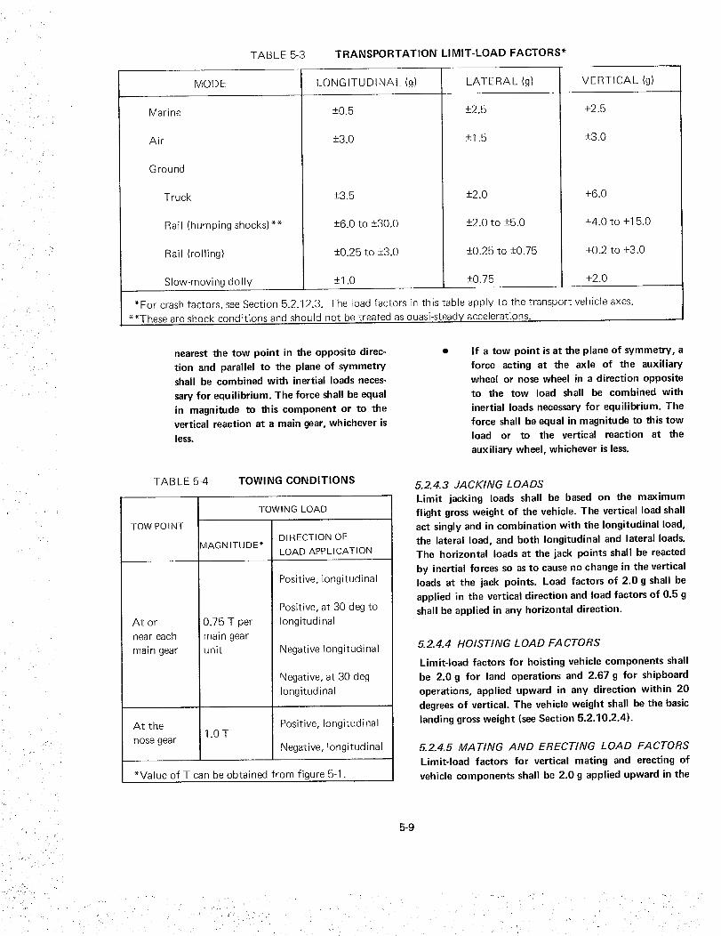
TABLE 5-3 TRANSPORTATION LIMIT-LOAD FACTORS*
MODE LONGITUDINAL (g) LATERAL (g) VERTICAL (g)
Marine
Air
Ground
Truck
Rail (humping shocks)**
Rail (rolling)
Slow-moving dolly
+3.5
+6.0 to +30.0
+0.25 to +-3.0
-+1.0
*For crash factors, see Section 5.2.12.3. The load factors in this table
+2.0
+2.5
-+3.0
+6.0
**These are shock conditions and should not be treated as quasi-steady
•+2.0 to +5.0
•+0.25 to +-0.75
-+0.75
+4.0 to +15.0
+0.2 to +3.0
+2.0
apply to the transport vehicle axes.
accelerations.
nearest the tow point in the opposite direc-
tion and parallel to the plane of symmetry
shall be combined with inertial loads neces-
sary for equilibrium. The force shall be equal
in magnitude to this component or to the
vertical reaction at a main gear, whichever is
less.
TABLE 5-4 TOWING CONDITIONS
TOW POINT
At or
near each
main gear
TOWING LOAD
MAGNITUDE*DIRECTION OF
LOAD APPLICATION
Positive, longitudinal
0.75 T per
main gear
unit
Positive, at 30 deg to
longitudinal
Negative Iongitudinal
Negative, at 30 deg
longitudinal
At the Positive, longitudinal1.0 T
nose gearNegative, longitudinal
*Value of T can be obtained from figure 5-1.
If a tow point is at the plane of symmetry, a
force acting at the axle of the auxiliary
wheel or nose wheel in a direction opposite
to the tow load shall be combined with
inertial loads necessary for equilibrium. The
force shall be equal in magnitude to this tow
load or to the vertical reaction at the
auxiliary wheel, whichever is less.
5.2.4.3 JACKING LOADS
Limit jacking loads shall be based on the maximum
flight gross weight of the vehicle. The vertical load shall
act singly and in combination with the longitudinal load,
the lateral load, and both longitudinal and lateral loads.
The horizontal loads at the jack points shall be reacted
by inertial forces so as to cause no change in the vertical
loads at the jack points. Load factors of 2.0 g shall be
applied in the vertical direction and load factors of 0.5 g
shall be applied in any horizontal direction.
5.2.4.4 HOISTING LOAD FACTORS
Limit-load factors for hoisting vehicle components shall
be 2.0 g for land operations and 2.67 g for shipboard
operations, applied upward in any direction within 20
degrees of vertical. The vehicle weight shall be the basic
landing gross weight (see Section 5.2.10.2.4).
5.2.4.5 MATING AND ERECTING LOAD FACTORS
Limit-load factors for vertical mating and erecting of
vehicle components shall be 2.0 g applied upward in the
5-9

00ttm
o<o--I
z
o
32
28
24
20
16
12
4 /
/oo 2o
6W + 45070
//
//
.3W
40 60 80 100 120 140
VEH ICLE WEIGHT, KIPS
FIGURE 5-1 TOWING LOADS
//T = 0.15W
/
160 180 200
vertical direction and 0.5 g in any horizontal direction.
The vehicle shall be within the attitude envelope
established for erecting and mating. The basic landing
gross weight (atmospheric) shall be used, without an
allowance for personnel.
5.2.4.6 MOORING
The vehicle shall be able to withstand ground winds
while secured in the static horizontal or vertical position
with control surfaces locked (see Section 6.1 ).
5.2. 4. 7 MASS PROPER TIES
Values of the design weights, centers of gravity, and
mass moments of inertia to be used for all
transportation and ground handling conditions shall
include the mass properties of the segments of the flight
vehicle being handled and transported, nonflight fluids
(e.g., temporary pressurizing gases), and supports which
are used during transportation and handling but are not
part of the flight vehicle.
5.2.5 PRELAUNCH
5.2.5.1 WIND AND GUST LOADS
The design shall account for static and dynamic loads
from ground winds and gusts and resulting vortex
shedding with possible lateral force amplification from
aerodynamic or gravity forces induced by the vehicle
response motion during the prelaunch phase. At least the
following effects shall be included: the forward profile
shape of the vehicle; vehicle mass, stiffness, propellant
Ioadings, and tank-pressurization conditions; protuber-
ances and surface roughness; and proximity and shape of
umbilical masts and other large structures. The turbu-
lence loads and steady loads (including gravity effects)
shall be suitably combined with the periodic vortex-
shedding loads calculated from the peak-wind profile to
obtain the resultant elastic-vehicle static and dynamicloads.
Tank-pressurization conditions shall account for the
venting-system characteristics, including valve tolerances
and settings for design ullage and vent pressure.
For recommended practices, see NASA SP-8008.
If a structural tie-off or damper is used with the
launch-support structure to assist the vehicle in
withstanding the wind loads, the vehicle attachment
loads shall be included in the total vehicle loads.
5.2.5.2 UMBILICAL LOADS
Umbilical loads on tTle vehicle shall be accounted for and
shall include the effects of umbilical configuration,
5-10

methodsof attachmentand separation,feed-linepressures,andwindloads.
For recommended practices, refer to NASA SP-8061.
5.2.5.3 GROUND-TEST FIRING LOADS
The following static and dynamic loads imposed on the
vehicle during ground-test firing of engines shall be
accounted for: (1) loads from ground winds and gusts;
and (2) loads from thrust buildup and decay, including
malfunction loads from any engine hard-over or out.
5.2.5.4 THERMAL EFFECTS
Thermal effects from at least the following sources shall
be included in evaluation of temperatures and thermal
stresses in critical areas of the structure:
Cryogens, including the effects of thermal
cycling
Environmental-control system, including the
effects of cooling-air pressure, temperature,
and humidity
Engine test firing, including the effects of
the test stand and ground
Atmospheric density, humidity, tempera-
ture, and wind velocity
• Solar radiation.
Refer to Section 5.1.2 for more detailed thermal-effec[s
cr teria.
5.2.5.5 MASS PROPER TIES
Values of the design weights, centers of gravity, and
mass moments and products of inertia to be used for
prelau nch conditions shall include: (1) the vehicle stages,
mated and unmated; (2) level of propellants; (3) vehicle
attitudes; (4) fueling sequences; (5) defueling sequences;
and (6) payload configuration.
5.2.6 LAUNCH
5.2.6. 1 WIND AND GUST LOADS
Static and dynamic loads from winds and gusts and
resulting vortex shedding and possible lateral-force
amplification during launch, as identified in Sec-
tion 5.2.5.1, shall be accounted for.
Wind directions not parallel to the plane of vehicle
symmetry, vortex shedding, and interference may cause
large asymmetrical loads on the vehicle.
5.2.6.2 ENGINE FIRING LOADS
The following loads imposed on the vehicle as a result of
engine firing during boost shall be accounted for:
Air loads induced by engine exhaust.
Acoustic loads, including the effects of the
launch system and the ground.
Thrust-buildup loads, including deviations in
engine start time, unsymmetrical side loads
on the engine nozzle, and any engine rota-
tion due to local deflections.
Thrust-vector misalignment loads. The
bounds of the total thrust-vector misalign-
ment shall be established by statistical
methods, considering all engines. (The mis-
alignment loads should be evaluated even
though the total thrust vector is normally
programmed to pass through the center of
gravity of the mated vehicle for the launch-
release condition.)
Loads resulting from engine hard-over or out
after release. These loads shall be based on at
least one engine hard-over or out, and on no
more than the number of engines which will
cause vehicle-control instability.
The analysis of the engine hard-over or out condition
should be in accordance with the procedure of
Section 5.2.12.1. If abort specifications include engine
conditions that result in vehicle instability, the analysis
should be in accordance with the procedures of
Sections 5.2.12.1 and 5.2.12.2.
The same loads shall be considered for engine hard-over
prior to release as for grou nd-test firing in the prelaunch
phase. In addition, rebound loads from emergency
engine shutdown prior to release, including thrust-decay
characteristics as well as all normal launch loads except
vehicle-release loads, shall be accounted for.
For recommended practices, refer to NASA SP-8030.
5.2.6.3 VEHICLE-RELEASE LOADS
Vehicle-release loads, including the effects of the release
mechanisms on the vehicle's dynamic response, shall be
accounted for.
5-11

5.2.6.4 THERMAL EFFECTS
Thermal effects from at least the following sources shall
be accounted for in determination of temperatures and
thermal stresses in critical areas of the structure:
(1) cryogens; (2) environmental-control system, includ-
ing the effects of cooling-medium pressure, temperature,
and humidity; (3) engine firing, including the effects of
the launch tower and the ground; and (4)atmospheric
tem perature.
5.2.6.5 MASS PROPERTIES
The values of the design weights, centers of gravity, and
mass moments and products of inertia to be used for the
launch conditions shall be based on the nominal
payloads and propellant loading. The mass properties
shall include upper and lower boundary values to
account for maximum and minimum payload weights
and center-of-gravity locations as well as tolerances on
propellants and other expendables. When pertinent data
are available, these boundary values shall be established
through statistical analysis of the tolerances.
5.2.7 ASCENT
5.2.7.1 LOADSAND PRESSURES
The determination of ascent loads and pressures shall
include consideration of the trajectory conditions of
Section 5.2.7.4 and of angles of attack in pitch, yaw,
and roll within the operational flight envelope. In
addition, the effects of the following shall be accounted
for: (1) in-flight winds, wind shears, and gusts;
(2) engine firing and shutdown; (3)staging; (4)inter-
ference from structure such as an attached stage,
protuberances, and control surfaces; (5) separated flow
regions and jet-plume interference on the flow fields;
(6) adding to or removing mass from the flow fields;
(7) shock impingement and interaction; (8) vent loca-
tions and sizes; and (9)vehicle flexibility on loading
distributions.
Experimental data shall be utilized when validated
theoretical or empirical data suitable to the configura-
tion and expected flight conditions are not available,
when the design angle of attack or yaw induces
nonlinear aerodynamic behavior, when large flow
separations are expected to occur, and when the
configuration has large protuberances or severe wake
generators. Experimental data shall also be utilized for
the transonic-speed regime.
5.2.7.1.1 WINDS, GUSTS, AND TRAJECTORIES
The wind and gust data specified in Section 6.1.3 shall
be used to determine structural loads during the ascent
phase. The design trajectories for ascent flight shall
include dispersions in the conditions that significantly
affect structural loads and temperatures.
For additional information, see Section 5.1.2.1.
5.2.7.1.2 ENGINE FIRING
Engine-thrust magnitudes, engine-firing sequence, thrust
transients, thrust-vector directional variations, and loads
resulting from the engine-out condition shall be
accounted for using the critical engine hard-over or out
condition (e.g., firing at launch).
The dynamic inputs for thrust excitation should be
derived from experimental data obtained from the
engine under consiseration, from similar engines, or
from a logical extraoolatior of related experimental
data. For recommended practices, see NASA SP-8030.
5.2.7.1.3 STAGING
The following sources of loads imposed on the vehicle
during staging shall be accounted for: separation or
actuation devices, fluid slosh, exhaust-plume impinge-
ment, control system, and vehicle-separation dynamics.
Analyses should employ multidegree-of-freedom models
incoroorating coupled vibration modes of the continuing
vehicle and of the jettisoned segmems.
For recommended practices, refer to NASA SP-8022,
SP-8030, and SP-8056.
5.2.7.2 THERMAL EFFECTS
Thermal effects from at least the following sources shall
be included in evaluation of temperatures and thermal
stresses in critical areas of the structure: cryogens;
engines; and external flow field, including shock and
engine-plume impingement areas.
For more detailed thermal-effects criteria, refer to
Sectior 5.1.2.
5.2.7.3 MASS PROPERTIES
The values of the design weights, centers of gravity, and
mass moments and products of inertia to be used for the
ascent conditions shall be based on the nominal payloads
and propellant loading. The mass properties shall include
upper and lower boundary values to account for
5-12

maximumandminimumpayloadweightsandcenter-of-gravitylocationsaswellastolerancesonpropellantandotherexpendables.Whenpertinentdataareavailable,theseboundaryvaluesshallbe establishedthroughstatisticalanalysisof thetolerances.
5.2.7.4 DESIGN TRAJECTORIES
The design trajectories for ascent flight shall satisfy
mission requirements and shall include dispersions in
trajectory parameters that have a significant effect on
structural loads and temperatures.
In establishing the design trajectories for structural loads
and thermal analyses, the effects of uncertainties in at
least the following parameters shall be accounted for:
aerodynamic characteristics, guidance and control
system characteristics, thrust and thrust-misalignment
tolerances, mass-property tolerances, atmospheric density
dispersions, and wind dispersions.
In evaluation of loads, the loads and temperatures on all
critical components shall be examined at a sufficient
number of points along the design trajectory to ensure
that all critical structural conditions are accounted for.
The evaluation shall include at least the following
trajectory points:
• Maximum dynamic pressure
• Where the product of the dynamic pressure
and angle of attack is a maximum
• Maximum longitudinal acceleration and
deceleration
• Where centers of pressure are at extreme
forward and aft locations
• Maximum heating rate
• Maximum temperature
• Maximum and minimum inertial loading
• Maximum differential pressure across the
structu re
• Transonic-speed regime (several points)
• Subsonic regime (one point)
• Pitch-yaw coupling for rolling vehicles
• Maximum and minimum pressure on com-
pression and expansion surfaces
• Maximum fluctuating pressure.
The effects of trajectory dispersion shall be determined
for all critical external aerodynamic-heating areas.
Laminar, transitional, or turbulent flow shall be con-
sidered in accordance with the transition criteria
employed for design.
5.2.8 SPACE
5.2.8. 1 ORBIT TRANSFER AND DEORBIT LOADS
The static and dynamic loads experienced by the vehicle
during orbit transfer and deorbit shall be accounted for.
For recommended practices, see NASA SP-8058 and
SP-8059.
5.2.8.2 DOCKING AND UNDOCKING LOADS
Loads imposed on the orbiter during docking and
undocking shall be accounted for, including the effects
of relative velocities and misalignments, liquid slosh
produced by docking and undocking, latching and
unlatching forces and torques, and engine thrust during
undocking and maneuvers. The following configuration
combinations shall be evaluated:
Orbiter - Orbiter.
Orbiter - Space station or base.
Orbiter-Space station or base- Other
orbiters.
The docking loads shall be evaluated using the relative
velocities and misalignments in table 5-5, although lower
values may be used if established by docking-simulator
studies.
The velocities and misalignments should be considered in
combinations limited by the following:
(V L - VLm )2 VR 2 DR 2+ + .
(AVL)2 (AVR)2 (ADR)2
COX2+ toy2 + OjZ2 _ X2 + _ y2 + _ Z2+ = 1
(A_) 2 (Ae) 2
where
V L and V R are the closing and lateral translationvelocities
5-13

TABLE 5-5 DOCKING LOADS For more detailed thermal-effects criteria, refer to
Section 5.1.2.
PARAMETER
Closing velocity (parallel to
docking port), fps
Lateral translation (in any
direction perpendicular to
closing velocity vector), fps
Angular velocity (in any plane),
deg/sec
Linear misalignment, in.
Angular misalignment (including
roll), deg
I M PACT
VALUES
0.4
0.15
0.1
+6.0
+3.0
DR is the linear misalignment,
VLM is the mean closing velocity,
COx, COy, and COz are the angular velocities aboutthe respective axes,
_x" _y' and _z are the angular misalignments aboutthe same axes, and
A is the increment to be considered above and
below the mean value or zero.
5.2.8.3 CARGO TRANSFER LOADS
All static and dynamic loads due to hatch opening and
latch forces, movement of cargo, control-system
interaction, and the absence of aerodynamic damping
and gravity in orbit shall be accounted for.
5.2.8.4 THERMAL EFFECTS
Thermal effects from at least the following sources shall
be included in evaluation of temperatures and thermal
stresses in critical areas of the structure" (1) cryogens;
(2) power supplies and other heat-producing equipment
in orbiters and in the space station or base; (3) engines,
including attitude-control and maneuvering engines;
(4) solar radiation; (5) albedo of the earth, moon, and
objects in interlunar space; and (6) radiation to space.
5.2.8.5 MASS PROPER TIES
The values of the design weights, centers of gravity, and
mass moments and products of inertia to be used for the
space-flight conditions shall be based on the nominal
payloads and propellant loading. The mass properties
shall include upper and lower boundary values to
account for maximum and minimum payload weights
and center-of-gravity locations as well as tolerances on
propellant and other expendables. When pertinent data
are available, these boundary values shall be established
through statistical analysis of the tolerances.
5.2.9 ENTRY
All static and dynamic loads and pressures acting on the
vehicle during entry, including their dispersions, shall be
accounted for. The determination of air loads shall
account for the effects of maneuvers, winds and gusts,
vehicle attitude, and shock impingement and inter-
actions associated with at least the following: protuber-
ances, canopies, fins, nose cap, deflected control sur-
faces, engine plumes, and boundary layer. Auxiliary
surface deployment, boundary-layer conditions, viscous-
induced pressures, body flexibility, and vorticity result-
ing from leading edges, intersecting flow fields, and
abrupt geometry changes shall also be accounted for.
Experimental data shall be utilized when validated
theoretical analyses applicable to the configuration and
flight conditions are not available and when the
configuration has large flow separations, protuberances,
or wake generators.
5.2.9. 1 THERMA L EFFECTS
Thermal effects from at least the engines and the
external flow field, including shock and engine-plume-
impingement areas, shall be included in evaluation of
temperatures and thermal stresses in critical areas of the
structure and in evaluation of the effectiveness of
thermal protection systems.
For more detailed thermal-effects criteria, refer to
Section 5.1.2.
5.2.9.2 MASS PROPERTIES
The values of the design weights, centers of gravity, and
mass moments and products of inertia to be used for the
5-14

entryconditionsshallbebasedonthenominalpayloadsandpropellantloading.Themasspropertiesshallincludeupperand lowerboundaryvaluesto accountformaximumandminimumpayloadweightsandcenter-of-gravitylocationsaswellastolerancesonpropellantsandotherexpendables. When pertinent data are available,
these boundary values shall be established through
statistical analysis of the tolerances.
The analysis at each gross weight should include all
reasonable distributions of pay load and disDosab le items.
These distributions should be presented in me form of
plots showing the variations n center of gravity in the
tlqree planes of the body's axis system.
Minimum Entry Gross Weight. Values of the minimum
entry gross weight shall include an allowance for
minimum crew, minimum propellant or other expend-
ables, and for a full load of cruise-engine fuel and oil. It
shall be assumed that no propellant remains for attitude
control and that there is no payload or other useful load
item.
Maximum Entry Design Gross Weight. Values of the
maximum entry design gross weight shall include an
allowance for full crew, full load of cruise-engine fuel
and oil, maximum payload, and any propellant
remaining in the primary propulsion system or other
expendables. It shall be assumed that all of the
attitude-control propellant remains and that there are
other useful load items.
5.2.9.3 DESIGN TRAJECTORIES
Entry-flight trajectories for use in determination of
structural loads and aerodynamic heating shall include
the dispersions in parameters in the design entry corridor
which have a significant effect on loads and temperatures.
5.2.9.3.1 DESIGN ENTRY CORRIDOR
The design entry corridor, defined in terms of velocity
versus altitude within the design atmosphere, shall be
represented by an envelope of operational trajectories
that satisfy the mission requirements.
A titude _nargins for the nominal trajectory values
should be derived from simulator studies involving
to erances and dncerta nties in systems and environ-
mental oarameters that have a significant effect on loads
and temoerature conditions. The trajectories should
include the ideal energy-management maneuver reouired
during -the nitial entry period to establish the desired
glide conditions. A design entry corridor (e.g., see
figure 5-2) should be develooed for NASA approval.
I-..i
/DESIGN ENTRY CORRIDOR J
f" "oPgoo.
FIGURE 5-2
VELOCITY, FPS
DESIGN ENTRY CORRIDOR
An acceptable approach to development of the corridor
follows:
1, rDefine the nominal entry corridor for ideal
conditions (no disoersions), using the ideal
entry trajectories from the baseline orbit and
from the critical orbits within the range of
inclinations specified for design. The top
(highest altitude) boundary is defined by an
ideal mmmum W/SC trajectory based on
maximum C L and minimum gross weight.The bottom boundary is defined by an ideal
maximum W/SC L trajectory for a maximumentry gross weight and a banK-angle history
required for the specified cross range.
Establish the effect on trajectory altitude of
incremental dispersions in each parameter
that has a significant influence on oadsand
heating. As a minimum, incrementat disper-
sions in the following parameters should be
considered:
A. Angle-of-attack dispersLons due to
tolerances and uncerta nties n the
pilot's instrumentation system, the
autopilot, the guidance and control
system, and [ne aerodynamic data.
B. Angle-of-roll dispersions aue to these
tolerances and uncertainttes.
C. Flight-path-angle and velocity disper-
sions at entry due to tolerances n the
effective retrorocket impulse resulting
from disoersions n vehicle attitude
retrorocket thrust, or burn lime.
D. Aerodynamic-coefficient dispersions.
5-15

i _ , ,
3o
E. Atmospheric-property dispersions
(including winds and gusts).
F. Uncertainty of orbit at retrorocket
firing.
The boundaries of the nominal entry
corridor should be expanded to account for
the incremental dispersions, and the ex-
panded boundaries should be based on
statistical combinations of the dispersions,
with consideration given to their coexistence
at the same time.
5.2.9.3.2 DESIGN ENTRY TRAJECTORIES
Design entry trajectories shall be based on the ideal
entry trajectories in the design atmosphere with
transient excursions out to the boundaries of the design
entry corridor. A sufficient number of trajectories shall
be established to ensure that all critical structural
heating and load conditions that occur in the design
entry corridor have been adequately covered.
5.2.9.3.3 TRANSIENT MANEUVER ENVELOPE
A transient maneuver envelope for entry flight shall be
established based on the aerodynamic capability of the
vehicle, the aerodynamic environment, and the type of
maneuver likely to be performed in each velocity range.
The critical combinations of loads, temperatures, and
other conditions represeJ,ted in the transient maneuver
envelope shall be accounted for.
Selection of the critical conditions should be based on
analysis of coexisting structural temperatures, loads,
pressures, and other parameters. The analysis should
account for the time-dependency and phasing of these
parameters.
A typical maneuver envelope (V-n diagram) for the entry
vehicle is illustrated in figure 5-3. The values for the
maximum normal load factors should include the
vehicle's particular entry characteristics, pilot-control
inputs, and the flight-control system characteristics for
tne initial entry and glide phases of flight.
During the initial entry period, prior to acquisition of
the glide conditions, the precise roll angle and angle of
attack should be modulated to avoid excessive structural
loads and induced environments, and to prevent skipout.
The oad factors should be established for conditions at
the boundaries of the design entry corridor and should
include the load factor for the ideal maneuver at the
boundary, plus an increment to provide capability to
maneuver away from the boundary.
.<Q
O--I
VELOCITY, V
FIGURE 5-3 TYPICAL ENTRY MANEUVER
ENVELOPE SHAPE
The transient maneuver envelope for the glide portion of
the entry should be based on conditions at the
boundaries of the design entry corridor. The load factor
for each velocity range should be based on the attitude
required for glide at conditions that define the design
boundary, plus an increment to correct for deviations
from the flight plan or to modify the flight plan.
Prior to completion of simulator studies conducted to
develop the actual maneuver load-factor requirements,
transient maneuver load-factor requirements may be
defined by using the static loads based on the vehicle
attitudes and conditions on the nominal entry boundary
and increasing them by 10 percent.
5.2.10 ATMOSPHERIC FLIGHT
The loads and environments experienced by the orbiter
structure in atmospheric flight and represented in the
V-n flight envelopes shall be accounted for. Conditions
imposed on the structure during atmospheric flight
which are more severe than those experienced in any
other flight phase shall be identified. The residual effects
of loads and environments encountered in space and
entry flight, including load redistribution from thermally
induced deformations, reduced material allowables, and.
changes in vibration modes and frequencies, shall be
accounted for.
5.2. 10. I LOADS AND PRESSURES
Loads shall be evaluated for the conditions identified for
the entry phase and for at least the following speeds:
level flight maximum speed, VH; limit speed, VL;
stalling speeds, VS, VSL , and VSPA; and the speed for
maximum gust, V G.
5-16
i •

• _.. 'i, _
The speeds used to determine loads for atmospheric
flight, not including takeoff and landing approach, shall
be defined for the altitude at which the limit speed, V L,
is maximum, the altitude at which the Mach number is
maximum, sea level, and for any intermediate altitude at
which critical loads occur. Sea-level speeds shall be used
for landing approach and takeoff loads.
Loads and pressures for both symmetrical and
unsymmetrical flight maneuvers shall be accounted for.
5.2.10.1.1 SYMMETRICAL FLIGHT MANEUVERS
For a balanced maneuver, it shall be assumed that the
vehicle is in the basic and landing configurations at all
points on and within the maneuvering envelope
illustrated in figure 5-4. The pitching velocity shall be
the finite pitching velocity for the load factor developed.
It shall be assumed that the elevator is deflected at a
very slow rate so that no pitching acceleration will
occur. In addition, at the limits of the envelope shown in
figure 5-4, the pitching acceleration shall be the
maximum attainable with the control system and in a
direction that reduces the load factor. Balance shall be
established between aerodynamic and inertial forces.
Except where vehicle design or the maximum static lift
coefficient makes it impossible to exceed a lower value,
the envelope shall be defined as follows:
The positive limit-maneuvering load factor
for any speed up to V L may not be less than
2.5.
The negative limit-maneuvering load factor
may not be less than 1.0 at speeds up to V H
and must vary linearly with speed from the
value at V H to 0 at V L.
For a symmetrical maneuver with pitch, thevehicle shall be in the basic and landing
configurations. The maneuver shall be based
on a rational pitching-control-motion-
versus-time profile.
Initially, the vehicle shall be in steady unaccelerated
flight at the specified airspeed and fully trimmed, for
zero control forces. The airspeed shall be constant until
the specified load factor has been attained. The load
factors to be obtained shall be all values on and within
the envelope illustrated in figure 5-4. The load factor at
each airspeed shall be obtained as indicated below for all
center-of-gravity positions:
By a control movement resulting in a tri-
angular displacement-time curve, as illus-
trated by the solid heavy lines of fig-
ure 5-5(a), provided that the specified load
factor can be attained by such control
+3
+CN MAX
+2
-- CN ,MAXBASIC
FIGURE 5-4
C D
IIII
m)
V LI )
=jEI
I
vH I
EQUIVALENT AIRSPEED, FPS
SYMMETRICAL MANEUVER ENVELOPE
5-17

/LOAD
*MAXIMUM AVAILABLE _ AS LIMITED BY
CONTROL-SURFACE STOPS OR HINGEMOMENT FROM A PILOT EFFORT OF200 LB, WHICHEVER IS LESS.
FACTOR
(b)
4_t,__
TIME (t)
FIGURE 5-5 LONGITUDINAL CONTROLDISPLACEIVlENT-TI ME DIAGRAM
movement; otherwise, by the ramp-style con-
trol movement illustrated by the dashed
straight lines of this figure. The time tl is
specified as 0.4 sec for the ramp-type con-
trol movement; the time t2 shall be the
minimum time required to attain the speci-
fied load factor while the control surface is
held at the stops.
By a control movement resulting in a ramp-
type displacement-time curve, as illustrated
by the solid heavy lines of figure 5-5(b). The
time t] is specified as 0.4 sec. The time t3
and the control displacement 6 shall be
sufficient to attain the specified load factor
in time 2ti+ t3.
In addition, for maximum aft center-of-
gravity position, the load factor shall be
obtained by a control movement resulting in
a ramp-type displacement-time curve, as
illustrated by the solid heavy lines of figure
5-5(c). The time tl is specified as 0.4 sec.
The time t4 and the control displacement 6
and -6/2 shall be sufficient to attain the
specified load factor at the same time as
-6/2 is attained.
For a symmetrical maneuver with the vehicle in the
landing-approach configuration, the vehicle shall be at
the limit speed, VLF, and the load factors shall be allvalues from 0 to 2.0. Balanced and symmetrical
maneuvers with pitch conditions shall be applied. The
longitudinal control displacement shall be the same as
ind icated for the basic and landing configu rations.
5.2.10.1.2 UNSYMMETRICAL FLIGHT MANEUVERS
For rolling pull-out, it shall be assumed that the vehicle
is in the basic and landing configurations. The airspeeds
shall be all airspeeds up to V L and the directionalcontrol shall be held in a fixed position for trim in
wings-level flight without rudder-control force and
displaced as necessary to prevent sideslip. Cockpit lateral
control shall be displaced to the maximum position, and
the control force shall be applied for not more than 0.3
sec. The control force shall be maintained until the
required change in angle of bank is attained, except that,
if the roll rate would exceed a specified value, the
control position may be reduced to produce the
sp_ ified roll rate after the maximum rolling acceleration
i,_ attained. The maneuver shall be checked by
application of the maximum displacement in not morethan 0.3 sec.
For accelerated roll, it shall be assumed that the vehicle
is in the basic and landing configurations. The airspeed
shall be all airspeeds up to V L and the initial load factorshall be all positive values between 0.8 and 1.0 of the
maximum values in the maneuver envelope shown in
figure 5-4. Initially, the vehicle shall be in a steady,
constant-altitude turn at an angle of bank to attain the
load factor at the specified airspeed. The vehicle shall
roll out of the turn through an angle of bank equal to
twice the initial angle. Constant airspeed and :¢,nstant
cockpit longitudinal-control position shall be main-
tained.
For roll in takeoff and landing configurations, the
airspeed shall be VLF in the landing-approach
configuration. The load factnr shall be unity. The lateral
control shall be displaced in accordance with the rolling
5-18
pull-out, and the roll need not be carried beyond a
60-degree angle of bank.
For sideslips and yawing, lateral control shall be
displaced to maintain the wings in a level attitude,
except that for high-speed rudder-kick conditions, an
angle of bank of not more than 5 degrees shall be
maintained.
The minimum speeds shall be the minimum speeds at
which the angle of bank can be maintained. For all of
the following conditions except one-engine-out opera-
tion, the normal load factor shall be unity:
1. Unsymmetrical thrust without sideslip. The
critical engine shall not be operating and the
vehicle shall be in the minimum drag
configuration. All other engines shall deliver
takeoff thrust or power. The vehicle shall be
in the takeoff and landing configurations at
VLF and in the basic and high-drag landingconfigurations at the maximum flight speed
obtainable with operating engines.
2. Engine failure. The vehicle shall be in the
basic configuration. The airspeeds shall be all
speeds from the approved minimum takeoff
speed for the one-engine-out condition to
V H. The critical engine shall suddenly fail.
If reverse thrust is possible because of
automatic features, the failed engine shall
deliver reverse thrust. All other engines shall
then deliver normal-rated power or thrust,
except that takeoff power or thrust is
applicable at speeds up to 2 VSL. Automatic
decoupling or thrust-control devices shall be
operating and alternately not operating.
With these devices operating, the structure
shall exhibit limit strength.
The directional control shall:
A. Be held in the neutral position until
maximum sideslip is attained.
B. Be moved to the position attainable
with maximum rudder deflection.
3. Steady sideslip. The vehicle shall be in the
basic and landing configurations. The air-
speed shall be all speeds up to V L. Rudder
control shall be applied slowly to a maxi-
mum position.
4. Low-speed rudder kick. The vehicle shall be
in the takeoff and landing configurations at
speeds up to VLF. The cockpit directional
control shall be displaced to a maximum
position in not more than 0.3sec. (The
maximum attainable displacement may be
limited by stops, or by the capacity of the
power-control system, or by a specified
directional control force.) The displacement
shall be maintained until the maximum
overswing angle of sideslip is attained and
the vehicle reaches a steady sideslip.
Recovery shall be made by reducing the
directional control to a O-degree displace-
ment angle in not more than 0.3 sec.
5. High-speed rudder kick. The vehicle shall bein the basic and landing configurations at
speeds up to VH. The cockpit directional
control force shall be applied in not more
than 0.2 sec. Recovery shall be made by
reducing the directional control to a
0-degree displacement angle in not more
than 0.3 sec.
6. One-engine-out. Sudden stopping of an
engine at all speeds above the approved
minimum takeoff speed for one-engine-out
operation up to V H shall not result in
unacceptable vehicle motions or vibrations
within this speed range. The limit loads on
the vehicle shall not be exceeded in a
symmetrical pullout to a load factor of 2.0,
with each engine, one at a time, inoperative
_nd all other engines delivering normal-rated
power or thrust.
These criteria snould not be used to moalr flightwc_thi -
ness or power-plant-installation requirements for one-
engine-out operation, and should be reexamined after
simu ation studies are made.
5.2.10.1.3 GUSTS
Loads for at least the following gust conditions shall be
accounted for: (1)symmetrical vertical gusts in level
flight, (2)lateral gusts, and (3)continuous turbulence
gusts.
5.2.10.1.3.1 Symmetrical Vertical
For symmetrical vertical gusts in level flight, the vehicle
shall be in the basic flight and landing configurations.
5-19

The symmetrical gust envelope, illustrated in figure 5-6,
shall be prepared in the following manner:
1,
2.
Velocities shall be as specified in table 5-6
except that at altitudes greater than 20 000
ft, the specified equivalent gust velocity,
Ude, shall be multiplied by the factors
_/r_/_-rr , where o h is density at a given
altitude and _r is density at 20000-ft
altitude,.
If flaps are utilized in landing, the vehicle
shall be assumed to encounter a head-on gust
of 25 fps at VLF.
To calculate the gust load factor, the follow-
ing assumptions shall be made: the shape of
the gust is
Ude (1 - 2_s_u = -_- cos-_-/
where
U = gusz velocitv, fps
Ude = derived gust velocity, fps
s = distance penetrated into gust, ft
TABLE 5-6 VELOCITIES FOR SYMMETRICAL
VERTICAL G USTS
POINTS
B ' and G'
C' and F'
D' and E'
I' and J'
CONFIGUR-
ATION
Basic
Basic
Basic
Landing
AIR
SPEED
(EAS)
V G
V H
V L
VLF
GUST
VELOCITY
(EAS)
Ude = 66 fps
Ude = 50 fps
Ude = 25 fps
Ude = 50 fps
3.
= wavelength of gust that tunes lowest
elastic mode of vehicle at the
velocity of interest, ft
Gust load factors vary linearly between
points B' through G', as shown in the gust
envelope in figure 5-6.
In the absence of a more rational analysis,
the gust load factors shall be computed as
follows:
Kg Ude VaR= 1+
498 (W/S)
÷1
S
0
FIGURE 5-6 SYMMETRICAL GUST ENVELOPE
5-20

• 'i_:, .' -
where
0.88 _g
Kg - 5.3 _-/_g- gust a leviation factor
2(W/S)
_g- pang
W/S = wing Ioading, psf
p = density of air, slugs/ft 3
g = acceleration due to gravity, fps 2
V = vehicle equivalent speed, kno_s
= mean geometric chord of wing, ft
a = slope of the vehicle normal-force
coefficient curve CNA per radian ifthe gust loads are applied to the
wings and qorizontal tai surfaces
simultaneously by a rational
method. (The wing-lift-curve-slope
C L per radiar may be used when thegust load is applied to the wings
only and tne horizontal tai gust
pads are treated separately.)
5.2.10.1.3.2 Lateral
The analysis shall consider that the vehicle encounters
lateral gusts normal to the plane of symmetry while in
unaccelerated wings-level flight (1) with all engines
operating, (2) with all engines not operating, and (3) in a
wings-level steady sideslip with the critical engine not
operating. The derived gusts and vehicle airspeeds
corresponding to conditions B' through J' (figure 5-6), as
defined for symmetrical gusts, shall be investigated. The
gust shape shall also be as specified for symmetrical
gusts. If an adequate analysis of the vehicle response to a
gust cannot be made, the gust loading on the vertical tail
surfaces shall be computed as follows:
Kg Ude VaSL -
498
where
L = vertical tail dad, Ib
S = area of vertica! tail, ft 2
and all other symbols are as defined for symmetrica
gusts.
5.2.10.1.3.3 Continuous Turbulence
For continuous turbulence gusts, the gust-loads spectra
shall be established using the normalized power spectra
of atmospheric turbulence and the procedures defined in
Section 5.3 of NASA TM X-64589. The vehicle structure
shall be designed for a 1 percent or lower risk of
exceeding limit loads during the expected time of
atmospheric flight. The analysis shall include at least the
dynamic response in the rigid-body modes of pitch and
translation. The dynamic response of the elastic modes
shall also be analyzed, as appropriate, and the analysis
shall include interaction of the elastic body and the
control system.
For information on winds and gusts, see Section 6.1.
5.2.10.1.4 MANEUVER AND GUST
Maneuver and gust envelopes shall be defined for at least
the transition- and cruise-flight regimes and for landing.
For transition flight, three envelopes shall be developed,
one each at maximum transition altitude, midtransition
altitude, and minimum transition altitude. The maxi-
mum normal load factor shall be derived from simulator
studies of the transition maneuver.
Prior to completion of these studies, the normal dad
fac[or of 2.5 for tne standard transoor; airolane
(figure 5-4, line A-D) may De use(].
For cruise flight, three envelopes shall be developed, one
each at maximum cruise altitude, ideal cruise altitude,
and sea level. The maximum normal load factor shall be
2.5 unless the vehicle has design features that make it
impossible to exceed a lower value.
For landing, two envelopes shall be developed, one at sea
level and one at 5 000-ft altitude.
A sufficient number of points on the maneuver and gust
envelopes shall be investigated to ensure that the
maximum load is obtained for each part of the vehicle
stru ctu re.
A conservative combined envelope may be used.
The design loads and loading distributions shall include
the significant forces acting on the vehicle and the effect
of pitching velocities in turns and pull-ups. The forces
shall be placed in equilibrium in a rational or
conservative manner. The linear and angular inertial
forces shall be in equilibrium with the externally applied
aerodynamic forces and moments.
5-21
k

/i , /
?'
5.2.10.1.5 ENGINES
All engine-operating conditions from zero to maximum
thrust and rpm values, including gyroscopic loads
associated with maneuvers and gusts, shall be accounted
for.
A limit lateral load factor shall be used which is at least
equal to the maximum load factor obtained in the
yawing conditions, but not less than 1.33.
The 1.33-limit lateral factor may be assumed to be
independent of other flight conditions.
A limit torque load imposed by an abrupt engine
shutdown from compressor jamming or other malfunc-
tion, or structural failure shall be accounted for.
5.2.10.1.6 DECELERATORS
Loads from the stowage and deployment of aero-
dynamic decelerators shall be accounted for. An analysis
shall be performed accounting for the effects of
deployment altitude, deployment rate, heating and
heating rate, and dynamic loads. The analysis shall use
the maximum dispersed velocity and altitude at
initiation of recovery, and the vehicle weight, center of
gravity, and tolerances at that time.
For ,ecommended practices, refer to NASA SP-8066.
5.2.10.1.7 HORIZONTAL AND VERTICAL TAILS
The air loads on the horizontal tail shall be distributed
symmetrically and unsymmetrically, in combination
with the specified maneuver and gust conditions. In
addition, the horizontal tail loads shall be distributed as
follows: 100 percent of the maximum load intensity
from the symmetrical flight conditions acting on one
side of the plane of symmetry and 80 percent of this
load intensity acting on the other side. The air loads on
the vertical tail or tails resulting from unsymmetrical
maneuvers and lateral gusts shall be determined.
5.2.10.1.8 PILOT-APPLIED LOADS
Pilot-applied loads (table 5-7) shall apply to manual,
manual-backup, and manually reversible cockpit control
systems having a conventional aircraft stick or wheel and
rudder pedals. Other cockpit control systems shall be
designed to a rationally determined set of control loads.
Dual ControlSystems. For vehicles with dual control
systems, 75 percent of the pilot-applied loads shall be
applied sire ultaneously at both control stations.
Duplicate Control Systems. For vehicles with duplicate
control systems, 100 percent of the pilot-applied loads
shall be applied to each system, assuming the other
system to be disconnected.
Powered Control Systems. For vehicles with powered
control systems, the power system shall be considered as
both operative and inoperative. For redundant systems,
a single system shall be considered inoperative.
Reactions. Forces reacting to the pilot-applied loads
shall be provided by:
Control-system stops only.
Control-system locks only.
Components specifically designed to react to
pilot-applied loads.
Irreversible mechanism only, locked and
with the control surface in all possible
positions.
Attachment of the longitudinal, lateral, and
directional control systems to their control-
surface horns when the corresponding cock-
pit controls are in all possible positions.
Each control system shall act separately.
5.2. 10.2 MASS PROPERTIES
The mass properties to be used for atmospheric flight
conditions shall include all practical arrangements of
movable items and all gross weights at the following
configurations and all lower weights down to and
including the minimum flying gross weight at which
critical loads are achieved:
Minimum flying
Basic flight (atmospheric)
Maximum flight (atmospheric)
Basic landing (atmospheric)
Maximum ferry and training flight
Ferry and training-flight landing.
5.2.10.2.1 MINIMUM FLYING
The minimum flying gross weight shall include an
allowance for:
Minimum crew
5 percent of cruise-engine fuel
5-22

TABLE 5-7 PILOT-APPLIED LOADS
AIRPLANECONTROL
Lateral
Longitudinal
Directional
COCKPITCONTROL
Stick
Wheel
Stick
Wheel
Rudder
pedal
qUMBER
OFFORCES
MAGNITUDEOF EACHFORCE(LBF)
100
80
100
25O
150
1O0
300
30O
POINT OFAPPLICATION
Top of stick grip
One force at any
point on circumfer-ence of wheel, other
force at diametrically
opposite point
On circumference
of wheel
Top of stick grip
One force at any
point on circum-ference of wheel,
other force at
diametrically
opposite point
Any point oncircumference of
wheel
Point of contact of
foot with pedal
Each force at point
of contact of foot
with each pedal
DIRECTION
A lateral force perpendicular to a
sl_raight line joining the top of the
stick grip and the pivot point
Each force tangent to wheel rim
acting in the same rationaldirection
Tangent to wheel rim in planeof wheel
A longitudinal force perpendicular
to a straight line joining the topof the stick grip and the pivot
point
Each force in same direction
perpendicular to the plane ofthe wheel
Perpendicular to the plane of thewheel
Parallel to the projection on the
airplane plane of symmetry of aline connecting the point of appli-
cation and the pilot's hip joint,
with the pilot's seat in its mean
flying position
Each force in same direction
parallel to the projection on the
airplane plane of symmetry of
a line connecting the point of
Brake
Flap, tab,stabilizer, spoiler,
alighting gear,arresting hook,
and wing-folding
operatingcontrols
Brake
pedal
Crank, wheel,
or lever
operated by
push or pullforce
Small wheelor
knob
3OO
3OO
Tip of pedal
Tip of pedal
3R___) Circumference of1 1 + 50 wheel or grip of
crank or leverbut not less than
50 nor more than
150 (R = radiusin inches)
133 in.-Ib if operated only by twisting
100 Ib if operated only by push or pull
application and pilot's hip joint,with the pilot's seat in its mean
flying position
Parallel to the projection on the
airplane plane of symmetry of a
line connecting the point of
application and the pilot's hip
joint, with the pilot's seat in itsmean landing position
Each force in same direction
parallel to the projection on theairplane plane of symmetry of
a line connecting the point of
application and the pilot's hip
joint, with the pilot's seat inits mean landing pbsition
Any angle within 20 deg of
plane of control
5-23

• Oil consistent with 5 percent fuel
• Hydraulic fluids
• Ballast.
For flying qualities, flutter-and-divergence prevention,
and vibration analyses, no fuel shall be assumed. No
other useful load items shall be assumed.
5.2.10.2.2 BASIC FLIGHT (ATMOSPHERIC)
The basic flight gross weight (atmospheric) shall include
an allowance for:
Full crew
Full load of cruise-engine fuel and oil
Maximum return payload
Full load of auxiliary power fuel and fluids
in other systems
Any propellant remaining in the primary
propulsion system or other expendables
40 percent of the propellant remaining for
attitude control.
The basic flight weight is applicable to flight-loads
computations, to flutter-and-divergence prevention, aqd
to vibration analyses.
5.2.10.2.3 MAXIMUM FLIGHT (ATMOSPHERIC)
The allowance for maximum flight gross weight (atmo-
spheric) shall be identical to the allowance for basic
flight except that the propellant for attitude control
shall be increased to 100 percent.
The maximum flight gross-wetgnt allowance is applicable
to taxiing, towing, ground handling, jacking, flutter-and-
divergence prevention, and vibration analyses.
5.2.10.2.4 BASIC LANDING (ATMOSPHERIC)
The allowance for basic landing gross weight (atmo-
spheric) shall be the basic flight allowance minus 50
percent of the cruise-engine fuel.
This weight allowance is applicable to orbiter landings
after entry, return from an aborted mission, and taxiing
and ground handling after landing.
5.2.10.2.5 MAXIMUM FERRY AND TRAINING
FLIGHT
The maximum ferry and training flight gross weight shall
include an allowance for:
Full crew
Full load of cruise-engine fuel and oil,
including auxiliary tanks
Full load of auxiliary power-system fuel and
fluids in other systems
Auxiliary propulsion-system modules and
ballast, if any.
No weight reduction shall be permitted for fuel used
during taxi, warmup, or climb-out.
The weight allowance for maximum ferry and training
flight is applicable to taxiing and ground handling,
takeoff, flight, flutter-and-divergence prevention, and
vibration analyses,
5.2.10.2.6 FERRY AND TRAINING-FLIGHT
LANDING
The weight allowance for ferry and training-flight
landings shall be the maximum ferry and training-flight
gross weight minus 50 percent of the cruise-engine fuel
and oil.
5.2.11 LANDING AND HORIZONTALTAKEOFF
All loads and environments imposed during landing and
horizontal takeoff, including taxiing, braking, andtakeoff run shall be accounted for. The residual effects
of loads and environments in atmospheric, entry, and
space flight shall be accounted for, including: (1) load
redistribution due to thermally induced deformations;
(2) reduced material allowables; (3) changes in vibration
modes and frequencies; (4) changes in oleo strut
characteristics; and (5) changes in tire characteristics.
5.2. 11. 1 LANDING LOADS
The range of expected landing velocities and their
distribution shall include provision for clearing a 50-ft
obstacle with power off.
At least the following landing loads shall be accounted
for:
Maximum spin-up load and maximum
spring-back load, each in combination with
the vertical load occurring simultaneously.
Dynamic analyses shall be made to obtain
the combined loads. The spin-up and spring-
back loads shall be the loads developed when
5-24

the sliding friction between the vehicle and
landing surface equals 0.55 or any lower
values that are critical. The touchdown
speeds shall be all values from VSp A to
1.3 VSPA, but not less than 1.2 VSL.
Maximum vertical load, in combination with
the drag load occurring at the instant of
maximum vertical load. The drag load shall
not be less than one-quarter of the maxi-
mum vertical load. Aerodynamic lift, acting
through the vehicle's center of gravity and
not exceeding the vehicle weight, may be
assumed to exist during the initial landing
impact.
5.2.11.1.1 SYMMETRICAL
Limit loads shall be determined for the weights of the
basic landing configuration, the maximum flight gross
weight configuration for taxiing, and for the following
symmetrical landing attitudes at the design sink speed:
Three-point landing, where the vehicle
design permits the main wheels and nose
wheels to contact the ground
simultaneously.
Two-point landing, where the main wheels
are in contact with the ground at the lowest
possible pitch angle, with the nose wheel
clear and not carrying load throughout the
landing impact.
Tail-down landing, where the vehicle is
assumed to be in an attitude corresponding
to either the stalling angle or the maximum
angle that allows each part of the vehicle
except the main wheels to clear the ground,
whichever is less. If the vehicle is equipped
with a tail bumper, the tail bumper shall be
completely compressed and in contact with
the ground, but with no load imposed on the
vehicle.
Nose-gear impact loads shall be determined
from analysis of the vehicle motion during a
landing in the tail-down attitude, with
appropriate applications of brake and nose-
down pitch control.
5.2.11.1.2 UNSYMMETRICAL
Limit loads for unsymmetrical landing conditions shall
include the effects of the vehicle motion in specified
crosswind and landing velocities.
Experience indicates the yaw attitude should be for a
zero sideslip with a 5-degree roll attitude and a pitch
attitude for a 1.1-g flare at a mean sink speed of 5 fos
and a mean horizontal touchdown speed of 1.1 VSp A.
Limit loads shall be determined for at least the
unsymmetrical drift and one-wheel landing conditions.
In drift landing, the vehicle shall be in the two-point
symmetrical landing attitude and (1) the vertical
reaction at each main gear shall be half of the maximum
value defined for two-point symmetrical landing
conditions; (2) the lateral load at one main gear shall
consist of an inward-acting load 0.8 times the vertical
reaction at that gear; (3) the lateral load at the other
main gear shall consist of an outward-acting load 0.6
times the vertical reaction at that gear; (4) no drag load
shall be applied; and (5) all external loads shall be
considered to act simultaneously at the point of contact
with the ground and to be balanced by vehicle inertia.
In one-wheel landing, the vehicle shall be in the
symmetrical two-point and tail-down landing attitudes
and (1) the loads shall be applied alternately to each
main landing gear with the drag and lateral loads equal
to zero; (2) with no load on the opposite main gear; and
(3) all external loads shall be considered to act
simultaneously at the point of contact with the ground
and to be balanced by vehicle inertia.
5,2. 11,2 TAXIING AND BRAKING LOADS
Loads from taxiing and braking, as well as loads from all
ground operations where the vehicle is operating
independently under its own power, shall be accounted
for. The vehicle shall be at its maximum flight gross
weight (atmospheric). For the braking conditions, the
landing gear and tires shall be in their static positions.
In straight taxi, the vehicle shall be in the three-point
attitude. No drag loads or lateral loads shall be applied,and the limit vertical-load factor shall be 2.0.
In turning, the vehicle shall be in the three-point attitude
and shall execute steady turns by means of differential
power or nose-gear steering. The vertical load factor at
the center of gravity shall be 1.0; at the ground, lateral
loads shall be applied so that the resultant of the vertical
and side loads passes through the center of gravity. The
same ratio of lateral-load to vertical-load components
shall be applied to all gears; and the sum of the lateral
loads shall be one half the vehicle weight, except thatthe side loads need not exceed a value which would
result in overturning.
5-25

In pivoting,the vehicleshallbe in the three-pointattitude,theverticalloadfactoratthecenterofgravityshallbe1.0,andthetirecoefficientoffrictionshallbe0.8.Withbrakeslockedonthewheelsofonegearaboutwhichthe.vehicleis rotating,thevehicleshallpivotaboutthecentroidof thecontactareaof allwheelsinthegear.
In two-pointandthree-pointbrakedrolls,theverticalloadfactoractingatthecenterofgravityshallbe1.2atthe landingconfigurationgrossweightand1.0at themaximumflight configurationgrossweight.A dragreactionat eachbrake-equippedwheelon thegroundshallbeassumedto actatthepointofcontactwiththegroundatamagnitudeof0.8oftheverticalreactionandshallbecombinedwiththeverticalreaction.
In unsymmetricalbraking,thevehicleshallbein theth-ee-pointattitudeandtheverticalloadfactoratthecenterof gravityshallbe1.0.Onemaingearshallbeassumedto bebrakedanddevelopingadragloadatthegroundequalto 0.8of theverticalreactionatthatgear.Thevehicleshallbeplacedinstaticequilibrium,withlateralloadsat themainandnosegearsreactingto theyawingmoment,andwithverticalloadsatthemainandnosegearsreactingto the pitchingmoment.Theforward-actingloadatthecenterof gravityshallbe0.8of theverticalreactionof thebrakedmaingear.Nolateralloadshallactatthecenterof gravity,andthelateralloadatthenosegearshallbeactingatthepointof contactwiththegroundanditsmagnitudeneednotexceed0.8of theverticalreaction.Thenosegearshallbealignedinafore-and-aftdirection.
In reversebraking,thevehicleshallhein atwo-pointattitudeandsupportedby themaingear,theverticalloadfactorat thecenterof gravityshallbe 1.0, and a
forward-acting drag reaction at the point of contact with
the ground which is equal to 0.8 of the vertical reaction
shall be combined with the vertical reaction for each
brake-equ ipped gear.
5.2. 11.3 TAKEOFF RUN AND ROTA T/ON LOADS
For the takeoff run, the vehicle shall be in the
three-point attitude. A dynamic analysis shall be
performed using the runway profiles specified in Section
5.2.11.4 to obtain vehicle loads. The landing-gear drag
loads due to discrete runway profile shapes shall be
included in the analysis, but the drag loads due to
friction shall be omitted. The analysis shall be co nducted
for at least three gross-weight conditions including the
maximum takeoff gross weight and the most critical
center-of-gravity location.
-[he dynamic analysis should include a minimum of six
degrees of freedom for the flexible vehicle in addition to
the landing-gear degrees of freedom.
The changes in landing-gear loads due to rotation,
starting with the vehicle leaving the runway in a
three-point attitude and ending when the climb angle is
achieved, shall be accounted for in vehicle design.
5.2. 11.4 RUNWAY AND TAXlWA Y ROUGHNESS
A model for runway and taxiway roughness shall be
specified for use in evaluation of ground loads.
5.2. 11.5 SUPPLEMENTARY LOADS
In addition to the loads imposed on landing-gear
assemblies by landing, taxiing, and braking, at least the
following loads shall be accounted for:
Rebound Loads. With the landing gear fully extended
and not in contact with the ground, a rebound-load
factor of --20.0 shall be assumed to act on the unsprung
weight of the landing gear along the line of motion of
the strut as it approaches the fully extended position.
Extension and Retraction Loads. With the landing gear
in each critical position between fully extended and
fully retracted, the loads shall consist of (1)
aerodynamic loads up to the limit speed specified for the
takeoff and landing configurations; (2) inertia loads
corresponding to the maximum and minimum symmetri-
cal limit-load factors specified for flight in the takeoff
and landing configurations; (3) inertia loads resulting
from maximum-powered accelerations of the landing-
gear components that move during extension or
retraction; and (4) gyroscopic loads resulting from
wheels rotating at a peripheral speed of 1.3 times the
stalling speed in the takeoff configuration while the
wheels are retracting or extending at the maximum rate
attainable.
Loads from Braking Wheels in Air. For the vehicle fly-
ing in the takeoff configuration with the landing gear in
any position, the vertical load factor shall be 1.0. The
airspeed and wheel peripheral speed shall be 1.3 times
the stalling speed in the takeoff configuration. The
maximum static braking torque shall be applied
instantaneously to stop the wheel rotation.
Tail Bumper Loads. A dynamic analysis of motion shall
be performed, considering: (1) that the vehicle rolls
backward at 5 mph at zero ground slope and the
5-26

maximum braking load based on a tire-to-ground
coefficient of friction of 0.8 is suddenly applied; and (2)
that for landings, the vehicle shall be in a tail-down
attitude at touchdown with the main gear and bumper
contacting the ground simultaneously.
5.2. 11.6 LOAD DISTRIBUTION ON MULTIPLE
WHEELS
The following load distributions for landing gears with
two wheels per unit shall be evaluated. A rational
approach shall be used for landing-gear configurations
having more than two wheels per unit.
For Symmetrical Distributions, the wheel loads shall be
equally distributed at the wheels of each landing-gear
unit.
For Unequal Tire Inflation, the wheel loads shall be
distributed so that 60 percent are on one wheel and 40
percent on the other wheel, except in drift and turning
conditions, when this distribution is .lot applicable.
For Flat-Tire Landing, the wheel loads resulting from
landing, reduced to 60 percent of the limit load, shall be
applied to each wheel separately.
For Flat-Tire Taxiing, the wheel loads resulting from
taxiing, reduced to 50 percent of the limit load, shall be
applied to each wheel separately.
For Flat-Tire Towing, the wheel loads resulting from
towing shall be applied to each wheel separately.
5.2. 11.7 MASS PROPERTIES
The mass properties to be used for landing and hori-
zontal takeoff conditions shall include all practical
arrangements of movable items and all gross weights of
the following configurations and all lower weights down
to and including the minimum flying gross weight at
which critical loads are achieved:
0
Minimum flying
Basic flight (atmospheric)
Maximum flight (atmospheric)
Basic landing (atmospheric)
Maximum ferry and training flight
Ferry and training-flight landing.
5.2.12 EMERGENCY CONDITIONS
Loads resulting from emergency conditions, including
malfunction, abort, crash, and ditching, shall be
accounted for.
5.2. 12. 1 MALFUNCTION
The transient conditions resulting from a malfunction
shall be analyzed as a single event.
The analysis required for malfunction conditions should
be conducted in conjunction with development of the
malfunction-detection system, the malfunction-
correction system, and the abort-initiation system. Based
on the structural design requirements and the analysis of
probabilities associated with malfunctions, the allowable
bounds of the parameters defining the malfunction
condition and the related time limits should be
established. For cases where system performance is
ncompatible with the time limits, data relative to the
tradeoff between mission degradation due to added
weight and increased risk should be assembled tofacilitate a choice.
5.2. 12.2 ABORT
The transient conditions resulting from abort shall be
analyzed as a single event, considering probabilities of
occurrence of all Ioadings and environmental parameters
and allowable risk for abort.
The analysis required for abort conditions, conducted in
conjunction with development of the abort system ano
procedures, should include the following:
Transient conditions resulting from emer-
gency staging and separation of the vehicle
stages at any time after liftoff or from
anotiqer space vehicle.
Effects of emergency systems and proce-
dures, SUCh as auxiliary propulsion or propel-
lant dumping, developed to facilitate return
of the vehicle to a stable cruise-flight
condition.
Initia _ransient and subsequent flight condi-
tions for personnel-escape systems, such as
ejection seals or escape pods.
All structural weight penalties imposed by abort condi-
tions snould be identified and submitted _o NASA for
approval.
5-27

5.2. 12.3 CRASH
The ultimate crash load factors relative to body axes
indicated in table 5-8 shall be used in design of structure
whose failure could result in injury to occupants during
a crash or prevent egress from a crashed vehicle,
The specified load factors are n the direction of the
acceleration Plus refers to forward, down, or right. The
longitudinal load factor should be directed forward
within a 20-degree semiangle cone whose axis is the
vehicle's longitudinal axis.
It shall be assumed that the fuel tanks contain the cruise
fuel which remains after half the internal cruise fuel has
been expended in the normal manner. The boost or
orbit-injection fuel shall not be included.
See Section 4.9.5 for additional information on
crashworthiness.
5.2. 12.4 DITCHING
The design shall minimize the probability that in an
emergency landing on water, the behavior of the vehicle
would cause immediate injury to the occupants or would
make it impossible for ther, _.to escape.
The probable behavior of the shuttle in a wa_er landing
should be investigated by model tests or by comparison
with airplanes of similar configuration for which the
ditching characteristics are Known. It must be shown
that under probable water conditions, the flotation and
trim of the vehicle will allow the occupants to leave it
See Section 4.9.5 for additional information on ditching.
5.2.13 BOOST-STAGE LANDING AND
RECOVERY
All static and dynamic loads and pressures acting on the
boost stages which result from staging and from the post-
staging trajectory, deployment of aerodynamic decelera-
tors, landing and towing in water, and recovery shall be
accounted for.
5.2. 13. 1 STAGING
The following additional sources of loads imposed on
the boost stages during staging shall be accounted for:
separation or actuation devices, exhaust-plume impinge-
ment, the flight control system, and vehicle-separation
dynamics.
For recommended practices, refer to NASA SP-8022,
SP-8030, and SP-8056.
5.2. 13.2 POSTSTA GING ENTR Y FL IGHT
All static and dynamic loads and pressures occurring
during poststaging entry flight shall be accounted for.
Heat transfer from engines and external flow fields shall
be included in evaluation of the structural temperatures
and thermal stresses.
5.2. 13.3 AERODYNAMIC DECELERATOR
DEPLOYMENT LOADS
Loads from the stowage and deployment of aerody-
namic decelerators shall be accounted for. An analysis
shall be performed accounting for the effects of
deployment altitude, deployment rate, heating and
heating rate, and dynamic loads. The analysis shall use
the maximum dispersed velocity and altitude at
initiation of recovery, and the weight, center of gravity,
and tolerances at that time.
TABLE 5-8 CRASH LOAD FACTORS
AR EA LONG ITU D I NA L VE RTICA L LAT E RA L
Crew and passenger compartments
Cargo and equipment areas
Large mass equipment-support structure
+2O
+10
+9
1.5
+10
+5
-2.0
+4.5
-+3
+1.5
-1.5
5-28

Forrecommendedpractices,referto NASASP-8066
5.2. 13.4 WATER IMPACT LOADS
Limit static and dynamic loads and load spectra shall be
determined analytically or experimentally for the boost
stage for a sink speed of 150 fps, for an impact attitude
of 20 degrees + 10 degrees with respect to vertical, and
for sea state Code 5.
Peak circumferential pressure distributions on the boost
stages shall be based on experimental data and special
structure such as a crushable shell shall be provided to
accommodate local peak pressures of high intensity
occurring for very short times.
For additiona information, see the Addendum to NASA
TM X-64589.
5.2. 13.5 WATER TOWING LOADS
Limit static and dynamic loads and load spectra shall be
determined for towing based on experimental pressure
data for sea state Code 3 and for a 7-knot tow speed.
Limit static and dynamic loads and load spectra shall be
obtained experimentally during wave slap in sea state
Code 5.
Wave slap consists of wave oressures on the vehicle while
it is floating in the water.
5.2, 13.6 RECOVERY LOADS
Loads resulting from recovery of the boost stages from
the water shall be accounted for in design. Stage weight
shall be no greater than the weight required to withstand
flight loads, insofar as practicable. Stage weight shall be
prevented from increasing by changing the design, or the
operation of the ground support recovery equipment, or
both. (See Addendum to NASA TM X-64589.)
5-29


6. NATURAL ENVIRONMENTS
This section identifies the basic natural environments
that must be accounted for in space shuttle design. These
environments can be found in Appendix E of the NASA
Space Shuttle Program Request for Proposal (No.
9-BC421-67-2-408), NASA TM X-64589, and NASA TM
X-64627. The latter two documents and their addenda
should be referred to for design values of natural
environment parameters not presented ir this section.
Where the criteria in this section are dependent on a
specific launch site or landing site, they have been based
on the Eastern Test Range, unless otnerwise indicated.
The criteria assume the space shuttle will avoid flight n
thunderstorms.
6.1 WINDS DURING LIFE PHASES
High Wind Operations. Opera_ions in high wind are those
that can be satisfied by reducing safety margins or
providing special equipment for high wind conditions.
These conditions include all vehicle ground operat ons n
peak winds exceeding 17.7 m/sec at the 18.3-m reference
altitude and associated 3a profile.
For the unfueled vehicle on the launch pad, the peak
ground wind speed should be 37.1 m/sec (72.1 knots)
from any azimuth at the 18.3-m reference altitude with
the associated 3o profile shape given n table 6-1.
TABLE 6-1 DESIGN PEAK WIND-SPEED
PROFILES FOR A 1% RISK OF EXCEEDING
THE 18.3-m REFERENCE LEVEL PEAK
WIND SPEED FOR THE WINDIEST
TWO-WEEK EXPOSURE PERIOD
The wind environment defined in NASA TM X-64589
shall be used for the space shuttle.
6.1.1 PRELAUNCH
All ground wind environments shall be as defined in
Section 5.2 of NASA TM X-64589. In particular, the
following environments shall be used: (1)peak wind
speed for exposure periods and percentiles of wind
exceedance and variation with height, (2) gust factors to
be applied to the peak design wind speed to obtain mean
wind speed, and (3) ground wind turbulence data.
Normal Wind Operations. Operations m normal wind are
those that can be satisfied without reducing safety
margins or adding special equipment beyond that pro-
vided for aunch. Normal wind conditions include peak
winds up to 17.7 m/sec (34.4 knots) at an altitude of
18.3 m (60 ft) above natural grade with the associated 3_
profile given in table 5.2.2 of NASA TM X-64589.
HEIGHT
m
18.3
30.5
61.0
91.4
121.9
152.4
(ft)
(60) 37.1
(100) 39.1
(200) 42.1
(300) 44.O
(400) 45.4
(500) 46.5
PEAK WIND SPEED
m/sec (knots)
(72.1)
(76.1)
(81.9)
(85.5)
(88.2)
(90.3)
To calculate peak wind-speed profile values associated
with the wind speeds up to 37.1 m/sec at the 18.3-m
level, as given in table 6-1, the following equation should
be em_)loyed:
t ) ,.314
h 1.6 (U18.3)
U(h) = U18.3 18.3
6-1
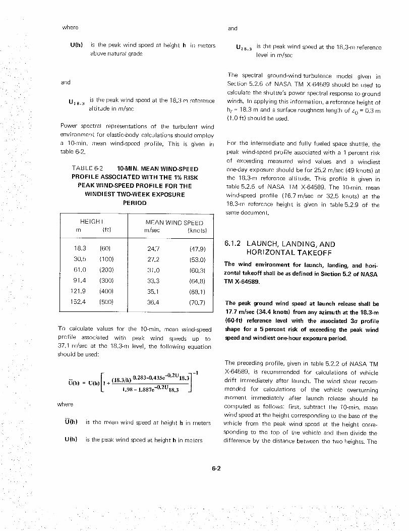
'/ • {
x ,
• • '2•
where
U(h) is the peak wind speed at height h in meters
above natural grade
and
U]8. 3 is the peak wind speed at the 18.3-m referencealtitude in m/sec
Power spectral representations of the turbulent wind
environment for elastic-body calculations should employ
a 10-rain. mean wind-speed profile. This is given intable 6-2.
TABLE 6-2 10-MIN. MEAN WIND-SPEED
PROFILE ASSOCIATED WITH THE 1% RISK
PEAK WIND-SPEED PROFILE FOR THE
WINDIEST TWO-WEEK EXPOSURE
PERIOD
HEIGHT
m
18.3
30.5
61.0
91.4
121.9
152.4
(ft)
(60) 24;7
(100) 27.2
(200) 31.0
(300) 33.3
(400) 35.1
(500) 36.4
MEAN WIND SPEED
m/sec (knots)
(47.9)
(53.0)
(60.3)
(64.8)
(68.1)
(70.7)
To calculate values for the 10-rain. mean wind-speed
profile assocrated with peak wind speeds up to
37.1 m/sec at the 18.3-m level, the following equationshould be used:
-1
Ii (18.3/h) 0"283-0.435e-0"2_ 18-3]U(h) = U(h) + 1.98- 1.887e-O'2U18.3 _J
where
U(h) is the mean wind speed at height h in meters
U(h) is the peak wind speed at height h in meters
and
U18.3 is the peak wind speed at the 18.3-m referencelevel in m/sec
The spectral ground-wind-turbulence model given in
Section 5.2.6 of NASA TM X-64589 should be used to
calculate the shuttle's power spectral response to ground
winds. In applying this information, a reference height of
hr = 18.3 m and a surface roughness length of zo = 0.3 m(1.0 ft) should be used.
For the intermediate and fully fueled space shuttle, the
peak wind-speed profile associated with a 1 percent risk
of exceeding measured wind values and a windiest
one-day exposure should be for 25.2 m/sec (49 knots) at
the 18.3-m reference altitude. This profile is given in
table 5.2.5 of NASA TM X-64589. The 10-min. mean
wind-speed profile (16.7 m/sec or 32.5 knots) at the
18.3-m reference height is given in table5.2.9 of thesame document.
6.1.2 LAUNCH, LANDING, AND
HORIZONTAL TAKEOFF
The wind environment for launch, landing, and hori-
zontal takeoff shall be asdefined in Section 5.2 of NASA
TM X-64589.
The peak ground wind speed at launch release shall be
17.7 m/sec (34.4 knots) from any azimuth at the 18.3-m
(60-ft) reference level with the associated 3o profile
shape for a 5 percent risk of exceeding the peak wind
speedand windiest one-hour exposure period.
The preceding profile, gwen in table 5.2.2 of NASA TM
X-64589, is recommended for calculations of vehicle
drift immediately after launch• The wind shear recom-
mended for calculations of the vehicle overturning
moment immediately after launch release should be
computed as follows: first, subtract the 10-min. mean
wind speed at the height corresponding to the base of the
vehicle from the peak wind speed at the height corre-
sponding to the top of the vehicle and then divide the
difference by the distance between the two heights. The
6-2

wind speeds at the top and base of the vehicle can be
found in tables 5.2.2 and 5.2.6 of NASA TM X-64589
(see 5 percent risk, 10-min. mean wind speed in
table 5.2.6).
The peak and mean wind environments given n the
preceding paragraph are recommended for takeoff and
landing studies. In addition, for simulations of the
orbiter landing and take-off-for-ferry, it is recommended
that the 10-min. mean wind profile expressed by the last
equation (Section 6.1.1) be used with a superimposed
discrete or continuous gust, as described in Sections
5.3.13 and 5.3.14 of NASA TM X-64589. The strong
wind-gust power spectra, as defined in Section 5.2.6 of
NASA TM X-64589, are recommended for power spec-
tral computations. A surface roughness length of
z o = 0.3 m should be used in the gust definition.
Landing wind shear should be computed by taking
(1) the mean wind speed at a neight of 152.4 m (500 ft)
and the peak wind speed at 18.3 m, and (2) the peak
wind speed at an a titude of 152.4 m and the mean wind
speed at 18.3 m for the design ground-wind-shear
profiles. For analyses o[ vehicle response to ground
winds in takeoff and landing while the orbiter is flying in
the aircraft operational mode, the wind should be
applied from the directions contained within the two
quadrants perpendicular to and upwind of the runway.
These directional design wind-speed-profile envelopes,
valid for +10 degrees of specified flight, azimuths, are
given in table 6-3. Also, see Section 5.3.5.2 of NASA TM
X-64589. The design wind-shear values to be used with
the wind speeds in table 6-3 are given in tables 5.3.11
and 5.3.1 2 of NASA TM X-64589.
On a mission launched from Vandenberg AFB, California
at a 182-degree flight azimuth, the 5-percent-risk direc-
tional wind-profile envelooes given in table5.3.10 of
NASA TM X-64589 and the wind shears given in tables
5.3.13 and 5.3.14 of the same document should be used
to establish control and structural design requirements.
Synthetic Profile with Discrete Gust. In the construction
of a synthetic wind-speed profile, the degree of correla-
tion between the wind shear and gusts should be taken
into account. This is accomplished by multiplying the
wind shears and the one-minus-cosine snaped discrete
gust having an amplitude of 9 m/sec (30 if)s) by a factor
of 0.85 before constructing the synthetic wind-speed
profile. This is approximately equivalent to taking the
combined 1-percent-risk values for the gusts and shears.
A series of synthetic wind-speed profiles should be
constructed, eacn profile with a different reference
height at which the design shear envelope ntersects the
design wind-speed-profile envelope.
For hot-day runway temperatures for orbiter oerform-
ance calculations, see Section 15.4 of NASA
TM X-64589.
6.1.3 ASCENT
The wind environments for ascent flight, including
in-flight abort, shall be as defined in Section 5.3 of
NASA TM X-64589. The winds used in establishing
vehicle design during ascent shall be the 5-percent-risk
directional winds for baseline missions launched from the
Eastern Test Range and having flight azimuths of
approximately: (1) 38 degrees with a 55-degree orbital
inclination; (2) 90 degrees with a 28-1/2-degree orbital
inclination; and (3) 180 degrees with a 90-degree orbital
inclination. These winds shall be used to establish the
synthetic wind profiles for vehicle design.
To determine the gust depth or "thickness," a series of
gusts, each with a different depth, should be calculated.
The design value of the gust depth of 60 to 300 m (about
200 to 1 000 ft) should be determined by selecting the
one associated with the most adverse condition. The
design synthetic wind-speed profile should be determined
by selecting the profile for the most adverse loading
conditions as determined by load computations. Details
on the construction of design synthetic wind-speed
9rofiles for use in the space shuttle structural analyses
are given in Section 5.3.8 of NASA TM X-64589.
Synthetic Profile with Gust Spectrum. The synthetic
wind speed-wind shear profile without discrete gust and
with an 0.85 factor on shears should be combined with
calculations on the vehicle response to the gust spectrum.
n place of the discrete gust, a spectral representation of
6-3

TABLE 6-3 DESIGN DIF;ECTIONAL STEADY-STATE WIND-SPEED-
PROFILE ENVELOPES FOR BOOST PHASE
GEOMETRIC RIGHT LEFTA LTITUDE HEAD WIND TAI L WIND CROSSWI N D CROSSWI ND
km (ft) meters per second (knots)
38-deg Flight Azimuth (55-deg Orbital Incl.)
80 (262 480)
75 (246 075)
60 (196 860)
5O (164050)
23 ( 75 463)
20 ( 65 620)
14 (45934)
10 ( 32 810)
1 (3281)
8O (262 480)
75 (246 075)
60 (196 86O)
5O (164050)
23 ( 75 463)
20 ( 65 620)
14 (45934)
10 ( 32 810)
1 ( 3 281)
80 (262 480)
75 (246 O75)
60 (196860)
5O (164 050)
23 ( 75 463)
20 ( 65 620)
14 ( 45 934)
10 ( 32 810)
1 (3281)
30 (58)
3O (58)
47 (91)
47 (91)
17 (33)
17 (33)
20 (39)
20 (39)
11 (21)
70
70
95
95
18
18
63
63
16
(136)
(136)
(185)
(185)
(35)
(35)
(122)
(122)
(31)
34 (66)
34 (66)
65 (126)
65 (126)
18 (35)
18 (35)
13 (25)
13 (25)
9 (17)
50 (97)
50 (97)
97 (188)
97 (188)
15 (29)
15 (29)
54 (105)
54 (105)
14 (27)
90-deg Flight Azimuth (28-1/2-deg Orbital Incl.)
5O
5O
72
72
25
25
2O
2O
11
(97)
(97)
(140)
(140)
(49)
(49)
(39)
(39)
(21)
90 (175)
90 (175)
120 (233)
12O (233)
25 (49)
25 (49)
75 (146)
75 (146)
20 (39)
30 (58)
30 (58)
52 (101)
52 (101)
8 (15)
8 (15)
28 (54)
28 (54)
13 (25)
2O
2O
3O
3O
7
7
29
29
9
(39)
(39)
(58)
(58)
(14)
(14)
(56)
(56)
(17)
180-deg Flight Azimuth (90-deg Orbital Incl.)
30
3O
52
52
8
8
28
28
13
(58)
(58)
(101)
(101)
(15)
(15)
(54)
(54)
(25)
20 (39)
20 (39)
30 (58)
30 (58)
7 (14)
7 (14)
29 (56)
29 (56)
9 (17)
9O
9O
12O
12O
25
25
75
75
2O
(175)
(175)
(233)
(233)
(49)
(49)
(146)
(146)
(39)
5O
5O
72
72
25
25
2O
20
11
(97)
(97)
(140)
(140)
(49)
(49)
(39)
(39)
(21)
6-4

. .j
gusts should be used. The oads resulting from the
synthetic wind profile can be calculated with a rigid- or
elastic-body trajectory.
The power spectrum -ecommended for elastic-body
studies is given by the following equation:
E(_) =683.4 (4 000_) 1'62
1 + 0.0067 (4 000K) 4"05
where the spectrum E(K) is defined so mat integration
over me domain 0 _<_<oo yields the variance of the
turbulence. In me preceding equation, E(K) is the power
spectra density (expressed in m 2 sec -2/cycles per m) at
wave numDer K per m. The design turbulence loads for
these calculations are obtained by multiplying the load
standard deviation by a factor of 3. The loads obtained
from application of this turbulence power spectrum
should be added to the rigid-vehicle loads resulting from
the use of the synthetic wind speed-wind shear profile
(with an 0.85 factor on shears) withoul a discrete gust.
This wind shear-spectrum combination will result n a
1-percem risk condition for the elastic-venicle studies
when employed with me design steady-state wind-speed
envelope values.
For further information on spectra of detailed wind
profiles, see Section 5.3.7.2 of NASA TM X-64689.
Vehicle Design Verification. t is recommended that a
variety of detsiled wind-profile data De used to calculate
final vehicle launch capability for a given launch site. The
data should be obtained from FPS-16 Radar/Jimsphere
wind-velocity profiles representatwe of each month.
6.1.4 ENTRY
The wind environments for entry flight shall be as
defined in Section 5.3 of NASA TM X-64589. The winds
used in establishing vehicle design during entry shall be
the 1-percent-risk, design-wind-speed-profile envelope
given in table6-4. The values given in this table,
representing idealized steady-state horizontal scalar wind
speeds, shall be applied without regard to flight azimuth
to establish the design winds for orbiter entry.
Synthetic Wind Profile with Discrete Gust. The 1-percent
design shear and gust values to be used with the
wind-speed profile in table 6-4 for construction of
synthetic profiles can be derived from tables 5.3.21 and
5.3.22 of NASA TM X-64589.
TABLE 6-4 DESIGN STEADY-STATE WIND-
SPEED-PROFILE ENVELOPE FOR ENTRY
ALTITUDE
km (ft)
150 (492 150)
115 (377 315)
80 (262 480)
75 (246 075)
60 (196 860)
50 (164 050)
23 ( 75 463)
20 ( 65 620)
14 ( 45 934)
10 (32810)
1 (3281)
WIND SPEED
m/sec (knots)
200 (389)
2O0 (389)
15O (291 )
160 (291)
190 (369)
190 (369)
40 (78)
40 (78)
92 (179)
92 (179)
28 (54)
Synthetic Wind Profile with Gust Spectrum. For these
calculations, the same winds should be used as for the
rigid-vehicle studies for orbiter entry, with the excepuon
of the discrete one-minus-cosine shaped gust. The dis-
crete gust should be replaced with the design turbulence
power spectrum presented for ascent flight.
Vehicle Design Verification. The entry winds for vehicle
design verification for an a titude of 18 km (about
60 000 ft) or ess should be 99 percent of the detailed
in-flight wind profiles in eacn monthly reference period
and for each specified entry flight azimuth.
6.1.5 ATMOSPHERIC FLIGHT
The expected gust exceedance rates given in table 6-5
shall be used to calculate limit and preliminary ultimate
loads. The normalized power spectra and exceedance
equation given in Section 5.3.12 of NASA TM X-64589
shall be used in horizontal or near-horizontal flight. A
second set of ultimate loads shall be obtained by
6-5

applyingappropriatedesignfactorsto thelimit loadsTheseloadsshallbecomparedwith the first setofultimateloadscalculatedaccordingto theappropriateexceedance rate in table 6-5, and the design ultimate
loads shall be the larger of the two.
TABLE 6-5 EXPECTED GUST EXCEEDANCE
RATES
LIMIT LOADS ULTIMATE LOADS
(exceedances per hr)
Non-Ferry Ferry Non-Ferry Ferry
2.22 x 10 -3 6.06 x 10 -4 1.11 x 10 -° 3.03 x 10 -7
For studies of the orbiter that do not include a ferrying
requirement, the total cruise time over the life of the
vehicle shall be considered to be 450 hr. For studies of
the orbiter that include a ferrying requirement, the total
flight time over the life of the vehicle shall be considered
to be 1 650 hr. These flight times shall be used to define
the expected shuttle gust exceedance rates for design.
The turbulence moael which should be used with the
flight simulator is given in Section 5.3.13 of NASA TM
X-64589. This model car be used for landing and cruise
flight simulations.
For certain horizontal flight studies, the use of a discrete
gust in load and flight-control system calculations is
desirable. Data on discrete gusts for horizontal flight
studies are given in Section 5.3.14 of XIASA
TM X-64589.
6.2 WATER IMPACT AND RECOVERY
When determining the capability of the solid-rocket
motors to withstand loads from water impact, recovery,
and transportation, the information in the Addendum to
NASA TM X-64589 shall be used.
6.3 NEUTRAL ATMOSPHERE DURING
LIFE PHASES
The atmospheric properties of pressure, temperature, and
density defined in the following sections shall be used in
space shuttle design.
6.3.1 LAUNCH AND ASCENT
The data on the Cape Kennedy Reference Atmosphere
(CKRA) in NASA TM X-64589, Section 14.7, shall be
used as nominal values to determine surface-to-insertion,
in-orbit, and abort trajectories and for analyses of
vehicles launched from the Eastern Test Range.
This model is available from the Computation Labora-
tory at Marshal Space Flight Center as Comouter
Subroutine PRA-63.
For vehicles launched from other sites, the annual
reference atmosphere given in Section 14.7 of NASA TM
X-64589 shall be used.
For design conditions involving extremes of pressure,
temperature, and density versus altitude, the coefficients
of variation (CV) from table 14.9 of NASA TM X-64589
and the mean values from table 14.1 of the same
document shall be applied as follows:
3CV.Maximum parameter = CKRA (1 +-_-_-_;
3CV.Minimum parameter = CKRA (1 - 1-_)
These extreme envelopes (mean +3 standard deviations)
should be used with caution. For example, extreme
values of tem0erature, pressure, and density at a given
a titude should not be used simultaneously. In addition,
the extremes of one parameter cannot exist for the entire
profile at a given time. However, i.r one is dealing with
atmospheric extremes of pressure, temperature, and
density independent of each other at discrete altitudes
and that analysis does not depend on atmospheric
conditions at other altitude levels, then the extreme
values derived from these equations may be used.
6-6

• i
6,3. 1. 1 EXTREME PROFILES
The hot and cold atmospheres given in Section 14.6 of
NASA TM X-64589 shall be used to represent the
atmospheric profiles for extreme density variation for
such design analyses as aerodynamic heating, engine
performance, and ferrying. The atmosphere producing
the most severe vehicle design condition shall be utilized
in vehicle design.
6.3.1.2 THERMODYNAMIC QUANTITIES ASSOCI-
ATED WITH EXTREME PRESSURE,
TEMPERA TURE, AND DENSITY VA L UES
For calculations in which two atmospheric variables are
related to a third extreme variable at discrete altitudes,
the functions given in Section 14.5 of NASA TM
X-64589 shall be used. Values for the coefficients of
variation and correlation for these calculations shall be
obtained from table 14.9 of NASA TM X-64589, and the
mean atmospheric values from table 14.11 of that
document.
6.3. 1.3 STANDARD DAY
For purposes of engine ratings, the sea-level values of
temperature, pressure, and density as given by the U.S.
Standard Atmosphere (1_2) shall be used.
6.3.2 SPACE
The properties of the neutral atmosphere for the space
phase of flight shall be taken from NASA TM X-64627.
6,3.2. 1 SUBORBITAL AND ORBITAL
(25- to- 1 O00-km Altitude)
In analyses of vehicle deorbiting conditions, the Marshall
Space Flight Center model atmosphere given in Appen-
dix B of NASA TM X-64627 shall be used to predict
the nominal gas properties and their variations in the
orbital altitude region of the atmosphere, plus the nomi-
nal gas properties in the 25-to-90-km (82000-to-
300 000-ft) region.
For calculations of the d_sign steady-state values of gas
properties of the orbital neutral atmosphere, a value of
230 shall be used for the mean 10.7-cm solar flux and a
geomagnetic index (ap) of 20.3 shall be used with a local
time of 0900 hr.
Short-time extreme values of the atmospheric gas proper-
ties used for design shall be calculated with a value of
230 for the mean 10.7-cm solar flux and a geomagnetic
index value of 400, and a local time of 1400 hr. (These
gas-property values for the orbital neutral atmosphere
represent an estimate of the conditions that may occur
for a short period of time- say, 12 to 36 hr- during an
extremely large magnetic storm.)
6.3,2.2 EXOSPHERE (37 O00-km Geosynchronous
Orbital AItitude)
The data given in Section 2.2.2 of NASA TM X-64627
shall be used to describe characteristics of the exosphere.
6.3.3 ENTRY AND ATMOSPHERIC FLIGHT
The U.S. Standard Atmosphere (1962) and dispersions in
the atmosphere as given in Section 14.8.1 of NASA
TM X-64589 shall be used for all orbiter entry heating
and performance analyses.
6.4 LIGHTNING DISCHARGES
The atmospheric electrical parameters given in Sec-
tion 9.2.2 of NASA TM X-64589 shall be used in all
phases of design to ensure shuttle integrity under
conditions of electrical discharges triggered by the
atmosphere during prelaunch, launch, and flight opera-
tions. However, the design shall not provide for inten-
tional penetration of thunderstorms during flight.
6.5 CHARGED PARTICLES
The electron density values and data in Section 2.3 of
NASA TM X-64627 shall be used to define the charged-
particle environment.
6,6 RADIATION
The radiation environment shall be defined from the
following criteria and from information in Section 2.4 of
NASA TM X-64627.
6-7

6.6.1 GALACTICCOSMICRADIATION
Galacticcosmicradiationshallbe accountedfor invehicledesign.
Galacticcosmicradiationconsistsof low-intensity,extremelyhigh-energychargedparticles.Theseparticles,about85percentprotons,13percentalphas,andtneremainderheaviernuclei,bombardthesolarsystemfromall directions.Theyhaveenergesfrom 108to 1019electronvoltsraer particle and are encountered nearly
everywhere n space. The intensity of this environment in
"free space" that is, outside the influence of the
earth's magnetic field is relatively constant (0.2 to 0.4
particles per square centimeter per steradian per second)
except during periods of enhanced solar activity, n these
periods, the fluxes of cosmic rays nave been observed to
decrease due to an increase n the strength of the
interplanetary magnetic field, which acts as a shield to
incoming particles. Near the earth, cosmic rays are
similarly influenced by the earth's magnetic field, result-
ing in a spatial variation in their intensity. The extreme
of the galactic cosmic ray environment occurs when the
sunspot activity is at a minimum. The environment _s
constant and may be scaled down [o 24 hr.
For additiona data on this subject, see Section 2.4.! of
NASA TM X-64627.
Estimates of the daily cosmic-ray dose for the various
orbits are shown n table 6-6. These dosages should be
considered in the space-shuttle design studies.
TABLE 6-6 GALACTIC COSMIC RAY
DOSAGE RATES
55-DEG
INCL.
POLAR GEOSYNCHRONOUS
ORBIT ORBIT
472 km 370 km
(255 nmi) (200 nmi)
rems per day
Solar
maximum 0.005
Solar
minimum 0.008
0.008
0.013
0.024
0.036
6.6.2 TRAPPED RADIATION
The trapped radiation environment shall be accounted
for in vehicle design. This environment shall be taken
from NASA SP-3024 or from the data obtainable from
the TRECO computer code provided by the NASA
Goddard Space Flight Center, and shall be merged with
trajectory information to find particle fluxes and spectra.
The fluxes and spectra should be converted to dosages
Dy using the NASA/MSC data or computer code. Only
the most recent data in NASA SP-3024 (currently in six
volumes) should be usea.
For additional information on trapped radiation, see
Section 2.4.2 of NASA TM X-64627.
Near-Earth Environment. The radiation belts trspped
near the earth are approximately symmetric with respect
to the azimuth except for the South Atlantic anomaly
wnere the belts reacn their lowest altitude. The natura
trapped radiatior n _ne anomaly region ,emains fairly
constant with t_me, althoug r it fluctuates with solar
activity. Electrons will be encountered at low altitudes ir
the anomaly region as well as in the auroral zones. Design
data requirements are given in Section 2.4.2.1 of NASA
TM X-64627.
Synchronous Orbit A/Etude Environment, The trappea
croton environment at syncnronous orbit altitude s of
no direct biological significance, but may cause deteriora-
tion of material surfaces over long exposure times. The
proton flux at this altitude is composed of only
low-energy protons (less than 4 V]ev) and is on the order
of 10 s orotons/cm2-sec. The trappea electron environ-
ment at syncnronous altitude is characterized by varia-
tions in particle intensity of several orders of magnitude
over periods as short as a few hours. However, for
extended synchronous altitude missions, a local rime-
averaged environment can be used. See Section 2.4.2,2 of
NASA TM X-64627 for additional data.
Solar Particle Events. The free-space particle event model
which should be used for space-shuttle orbital studies is
given n Section 2.4.3.1 of NASA TM X-64627. Solar
particle events are emissions of cnarged particles frorr
disturbed regons on the sun during solar flares. They are
composed of energetic protons and alpha particles that
occur sporadically and last for several days.
6-8

6.7 METEOROIDS
The meteoroidenvironmentwhichthe spaceshuttlemustwithstandshallbebasedonthemeteoroidmodeldefinedinSection2.5.1ofNASATIVIX-64627.
6.8 ASTRODYNAMICCONSTANTS
TheastrodynamicconstantvaluesgiveninSections1.6and2.7ofNASATMX-64627shallbeused.
6.9 RAIN
The rain environment defined in NASA TM X-64589
(tables 4.1 and 4.4) shall be used in evaluation of the
accumulated damage from rain, The total vehicle
exposures to rain shall be consistent with the data of
table 4.3 of NASA TM X-64589 and with the specified
intervals between refu rbishment of components.
6,11 BLOWING SAND AND DUST
Blowing sand and dust environments which the vehicle
must withstand or be protected against shall be as
defined in Section 6 of NASA TM X-64589.
Particle size, hardness, and distribution are indicated n
the NASA document for windb own sand and dust. If
qualification tests in a windblown-sand environment are
required, the following conditions should be used:
particle size, 0.08 to 0.12 mm (3 x 10 -3 to 5 x 10 -3 in.);
hardness, 7 to 8 moh; distribution, 0.02 g/cm 3 (1.2
Ibm/ft3); wind speeo, ]0m/sec (32.8 fps); duration of
exposure, 10 hr.
If aualification tests n a wndblown-dust environment
are required, the following conditions should be used:
particle size, 1 x 10 -4 to 2x 10 -4 mm (3.94x 10 -6 to
7.88x 10 -6 in.); hardness, 7 to 8moh; eistribution, 6x
10 -9 g/cm 3 (3.744 x 10 -7 Ib/ft3); wind speed, 10 m/sec
(32.8 fps); duration of exposure, 10 hr.
6.10 HAIL 6.12 SALT AIR
The number of vehicle exposures to hail and the severity
and duration of such exposures shall be specified for an
evaluation of the potential damage from cumulative
effects of hail. As an alternative, the hail environment
which the vehicle must withstand or be protected against
shall be equivalent to a single exposure to 50 mm (2 in.)
of hail over a duration of 15 min., with a velocity of fall
of 30.5 m/sec (100fps), mass density of 0.80g/cm 3
(50 Ibm/ft 3 ), and wind speed of 10 m/sec (32.8 fps).
Size distributions shall be:
Diam Range
cm (in.)
Number of Hailstones
per cubic meter (cu ft)
0 to 1 (0 to 0.4) 22.00 (776.8)
1 to 2 (0.4 to 0.8) 0.80 (28.2)
2 to 3 (0.8 to 1.2) 0.17 ( 6.0)
Variation in hail hardness with temperature shall be as
indicated in table 6.2 of NASA TM X-64589.
A model of the salt air environment which the vehicle
must withstand shall be specified.
For further qformation, see Section 10 of NASA TM
X-64589.
6.13 HUMIDITY
The humidity which the vehicle must withstand shall be
specified.
For further information, see Section 3 of NASA TM
X-64589,
6.14 FUNGI AND BACTERIA
Models of the fungi and bacteria which the vehicle must
withstand or be protected against shall be specified.
For further information, see Section 11 of NASA TM
X-64589
6-9


7. PROOF OF DESIGN
Proof of structural adequacy of the design under all
critical combinations of design loads and environmental
conditions shall be provided by analyses and tests, all of
which shall be documented.
7.1 DOCUMENTATION
Reports shall be prepared on analyses and tests con-
ducted to verify the structural adequacy of the design.
Assumptions, methods, and data used shall be defined.
References cited in the reports which are not readily
available shall be submitted to NASA with the reports.
The reports shall cover at least the following:
Integrated plan for proving
adequacy
• Tests
Material characterization
Development
Qualification
Acceptance
Flight
Special
structural
Analyses
Physical characteristics of structure
Interfaces
Operating restrictions
Inspection and repair
Operational-usage measurements.
Where appropriate to ennance understanding, the reports
should De subdivioeo according [o the life phases qo[eo
n Section 5.2.
7.1.1 INTEGRATED PLAN
An integrated plan shall be prepared which describes the
total plan for verifying structural adequacy. All signifi-
cant analyses and tests and the schedules for their
accomplishment shall be identified for structure and
structural characteristics requiring proof.
The test plan shall include tests to characterize materials,
structural components, or assemblies; development tests;
qualification tests; acceptance tests; flight tests; and
special tests.
The plan shall be revised as necessary to reflect changes
in schedules, requirements, objectives, design character-
istics, and operational usage.
7.1.2 TEST DOCUMENTATION
Z1.2.1 TESTPLANS
A comprehensive test plan shall be prepared for each
individual test prior to conducting the test. The plan
shall include a description of the test purpose, test
conditions, test procedures, test sequence, test articles,
requisite data, instrumentation, accept-reject criteria, and
provisions for complete documentation.
Where the test articles differ from the actual flight
hardware and where design and test loads differ, such
differences shall be identified and the consequences of
these differences assessed. Test plans shall be approved
by NASA.
Z 1.2.2 TESTREPORTS
Test reports shall include the test results, conclusions,
and recommendations; also, in case of failure, these
reports shall describe the failure, the failure condition,
the cause of failure, and the cor. ective action taken.
7-1

7.1.3 ANALYSIS DOCUMENTATION
Reports shall be prepared on analyses made to verify
structural adequacy in compliance with the criteria of
Sections4 through 6. The reports shall be divided
logically by subject and shall include the results of
analyses to determine at least the following:
• Induced environment analysis (see Section
7.2.1)
• Natural environment analysis (see Section 6)
• Material selection and characterization anal-
ysis (see Section 7.2.2)
• Loads analysis (see Section 7.2.3)
• Thermal analysis (see Section 7.2.4)
• Structural analysis (see Section 7.2.5)
• Aeroelastic analysis (see Section 7.2.6).
The analyses shall be reported according to the life
phases specified in Section 5.2 where appropriate.
7.1.4 PHYSICAL CHARACTER ISTICSOF STRUCTURE
The physical characteristics of the boost stages and
orbiter which are significant to the design of the vehicle
structure shall he described and controlled by appropri-
ate documentation, procedures, and policies. The
physical description in the documentation shall include
at least the following data for each stage: (1)vehicle
dimensions, (2) aerodynamic surface areas, (3) station
locations, (4) unit weights, (5) center of gravity, (6) dis-
tribution of mass and inertia, (7) distribution of stiffness,
(8) detailed structural dimensions, and (9) physical inter-
faces with other systems. The detail and accuracy of the
documentation shall be sufficient to provide a basis for
all structural analysis.
7.1.5 INTERFACES
Physical and functional interfaces of the structure and
other components, assemblies, systems, liquids, and gases
shall be identified in the documentation. Interfaces
within each vehicle, between vehicles, with external
vehicles, and with test and ground support equipment
shall be accounted for. Methods of controlling and
accounting for interfaces shall be defined.
7.1.6 OPERATING RESTRICTIONS
Re ports shall be prepared on vehicle-operating
restrictions which state the strength of the structure and
any limitations on preparation, testing, and operational
use of the vehicle.
7.1.7 INSPECTION AND REPAIR
Reports shall be prepared on inspection and repair of the
vehicle. The reports shall include: techniques for
inspecting structure to locate hidden defects, deteriora-
tions, and fatigue effects; and instructions for repair and
replacement, modified as necessary on the basis of
flight-test experience.
7.1.8 OPERATIONAL-USAGEMEASUREMENTS
A plan shall be prepared for measurement of loads and
temperatures during vehicle operation.
Reports shall be prepared on operational-usage measure-
ments. These reports shall define the recording and
monitoring systems for evaluating structural adequacy
during operational usage. In case of failure, these reports
shall describe the failure, the failure condition, the cause
of failure, and the corrective action taken.
7.2 ANALYSES
Analyses shall be performed to verify structural
adequacy in compliance with the criteria of Sections 4
through 6. Where theoretical analysis is inadequate or
where experimental correlation with theory is
inadequate, the analysis shall be supplemented by tests.
7.2.1 ENVIRONMENTAL ANALYSES
Analyses shall be performed to define the induced
environments acting on the vehicle.
7.2.2 MATERIALS ANALYSES
Analyses shall be performed in accordance with the
criteria of Section 4.6 to determine the suitability of
materials selected for use in the design environment and
7-2
to define the allowable mechanical and physical
properties of new materials or of existing materials in
new environments.
7.2.3 LOADS ANALYSES
Loads analyses shall cover the static and dynamic loads
and load spectra expected to be imposed on the vehicle
during its service life. The analyses shall be made
according to the life phases specified in Section 5.2. All
critical loads and combinations shall be defined.
The analyses shall account for (1)vehicle geometry;
(2) flight conditions such as altitude, velocity, and load
factors; (3) weight conditions; (4) inertial properties;
(5) vehicle and control-system stiffness distributions;
(6) vehicle vibration-mode frequencies and structural
damping; (7) structural interaction with the control
system; (8) variation of loads with time for deterministic
load analyses, and (9)all statistical Ioadings for proha-
bilistic load analyses.
Computed static and dynamic loads and load spectra
shall be combined with thermal effects to produce
vehicle-critical design loads, test loads, and data for use
in establishing strength and operating restrictions on the
vehicle.
7.2.4 THERMAL ANALYSES
Thermal analyses shall be made of the induced thermal
environment and of the vehicle response to this environ-
ment. The analyses shall be made in compliance with the
criteria presented in Sections 4 through 6 and according
to the life phases specified in Section 5.2.
These analyses shall account for the flight conditions
which affect heating in all phases of the vehicle's life.
These flight conditions shall include, but not be limited
to (1)maximum heating trajectories, (2)aerodynamic
heating, (3) exhaust-plume heating from the propulsion
and control systems, (4) propellant-tank levels, and
(5) orbit definition and orientation. The analyses shall
also account for the effects of structural materials and
their properties, structural components and their
assembly, insulation materials, and internal energy
sources.
7.2.5 STRUCTURAL ANALYSES
Structural analyses shall be made covering strength,
deformation, leakage, and structural response to the
critical loads, environments, and temperatures antici-
pated during the service life of the vehicle. These
analyses shall define the critical combination of loads,
conditions, material properties, and interactions which
determine stress levels and margins of safety for all
structural components.
The structural analyses shall also include investigations of
fatigue, safe-life, and fail-safe considerations to establish
the service life; tolerance of the structure to crack-like
defects; and residual strength and damage tolerance.
Analyses shall also be performed to show that deforma-
tions do not cause degradation of vehicle performance.
7.2.6 AEROELASTIC ANALYSES
Static and dynamic aeroelastic analysis shall account for
the following in all phases of the vehicle's life: vehicle
geometry; flight conditions, weight conditions, and
corresponding mass properties; vehicle and control-
system stiffness distributions, structural interaction with
the control system and the propellant system; stationary
and nonstationary aerodynamic coefficients; interface
with thermal characteristics; and stability margins.
7.3 MATERIAL CHARACTERIZATIONT ESTS
When structural material characteristics, including
physical and allowable mechanical properties and failure
mechanisms, are not available in NASA-approved
references, tests shall be performed to characterize the
materials in accordance with the criteria of
Sections 4.6.1 through 4.6.3.
For recommended practices, refer to NASA
NHB 8080.1, NHB 8080.3, MIL-HDBK-SB, and
A F M L-T R-66-386.
7.3.1 PHYSICAL PROPERTIES
Material physical properties, including
properties, shall be determined by test.
thermal
7-3

Z i_
• • :i _ Z _ •
i!• _: i:z
Physical properties should include, as appropri-
ate: density, coefficient of thermal expansion, thermal
conductivity, specific heat, solar absorptance, and infra-
red emittance. For recommended practices, refer to
NASA SP-8014, SP-8043, NASA NHB 8080.3, MIL-A-
008860A (USAF), MIL-STD-143B, MIL-STD-810B, and
ASTM E 332-67.
7.3.2 ALLOWABLE MECHANICAL
PROPERTIES
Allowable mechanical properties shall be determined by
experiments that account for appropriate thermal and
chemical environments.
Mechanical properties should include allowable values for
tensile and compressive yield strengths, tensile and
compressive ultimate strengths, bearing and shear
strengths, strength under combined loads, moduli of
elasticity, Poisson's ratio, and material elongation.
Sufficient test data should be obtained to account for
scatter in the data. Where applicable, inspection pro-
cedures, accept-reject criteria, the effect of manufactur-
ing processes on material properties, and protective-
surface treatments should be determined.
7.3.3 FAILURE MECHANISMS
Tests shall be performed on structural materials, as
applicable, to determine their susceptibility to failure by
the following failure mechanisms:
• Fatigue
• Brittle fracture
• Stress-corrosion cracking
• Hydrogen embrittlement
• Temper embrittlement
• Creep
• General corrosion
• Galvanic corrosion
• Meteoroid-impact damage
• Radiation damage.
Fatigue. The fatigue characteristics of structural
materials shall be determined by test. These tests shall be
made in the combined environment used for design
representing static loads, dynamic loads, temperature,
vacuum, and corrosion. Provision shall be made to reduce
allowable stresses to account for scatter in the test data.
The test loading conditions, environments, and stress
states should represent as accurately as possible those
expected during the service life of the structure.
Brittle Fracture. The brittle-fracture characteristics of
thick-wall and heavy-forged sections will be required for
the vehicle structural design. The tentative standard
testing procedures developed by ASTM Committee E-24
should be applied.
In conjunction with evaluation of brittle fracture,
fracture toughness should be determined by experiment.
Flaw-growth characteristics and the threshold stress
intensity of materials should be determined by tests
when the materials are used for structural components
designed for safe-life.
When experimentally determining the fracture toughness
of materials, the test specimens should be sufficiently
wide to prevent in-plane bending and should be of the
same material and thickness as tlqe structural assemblies,
and processed in the same manner. A sufficient number
of specimens having flaws of various sizes and simulating
the parent metal, weldments, and heat-affected zones of
the pressure vesseJs should be tested to allow meaningful
statistical values of fracture tougnness to be established.
When experimentally determining the flaw-growth char-
acteristics of material, the test specimens shou d be
designed to eliminate detrimental effects such as in-plane
bending and back-face corrections. A sufficient number
of tests should De conducted in the simulated service
environments and at the service load frequencies to allow
meaningfu statistical values of flaw-growth char-
acteristics to be established. In addition, flaw-growth
tests of specimens simulating theactua structural thick-
ness, expected service loading and environment, and the
anticipatec flaw geometries should be conducted on
critical structural components such as pressure vessels to
verify the calculated flaw-growth predictions.
7-4

When experimentally determining the threshold stress-
intensity characteristics and sustained-stress flaw-growth
rates selected for assemblies subjected to sustained loads,
the specimens should De tested n environments simu-
lating the actual service environments as nearly as
practicable. A sufficient number of specimens should De
testea to allow meaningfu! statistica values of the
material's mreshold stress intensities to be established.
:or recommended practices, refer to NASA SP-8040 and
SP-8095.
Stress-Corrosion Cracking. There are no universally
accepted test proceaures to determine stress-corrosion
cracking. The sample configurations most often used are
identical to those used for hydrogen-embrittlement tests.
Short-time cyclic immersion n salt water and exposure
to the sea-salt environment are the most common [ypes
of tests.
The synthetic sea-water solution used should be as
designated Dy the American Society of Testing Materials.
Other corrosive environments such as air, gas, or fuel can
also be used for test conditions, where appropriate.
Hydrogen Embrittlement, The sustained load-carrying
ability of metals susceptible to hvdroger embdttlement
(particularly, steels and titanium alloys) should be
evaluated by laboratory tests.
A variety of specimen configurations such as the pre-
stressed bent beam, split-ring, aqd notched types can be
used. Safe threshold working-stress levels may be
established for materials susceptible to hydrogen-induced
embrittlement by subjecting specimens to the anticipated
hydrogen environment. Safe or tolerable 'evels of
hydrogen absorpt on should be determined for titanium
alloys. The effects of possible hydrogen absorption from
fabrication processes such as chemical milling, pickling,
and cleaning prior to plating should be determined for
steels and titanium alloys. For steels, no dangerous or
embrittling levels of absorption should be permitted to
occur from these processes. For titanium alloys, the level
of hydrogen absorbed during processing should be
determined by hydrogen analyses. This level must be
safely below the previously determined tolerable limits.
Temper Embrittlement. Tests should be made on
representative coupons to verify that temper embrittle-
ment has not occurred.
Creep. Creed tests for candidate structural materials
should be conducted at elevated temperatures dnless
valid comparisons can be made from results of prior tests
that are acceptable to NASA. Standard procedures of the
American Society of Testing Materials should be
followed for creep tests on materials. (There are no
established standard procedures for such tests on
structural assemblies.)
The effects of temperature overshoot and temperature
cycling on the creed properties of sensitive materiats
should be determined.
General Corrosion, Typical corrosion tests for evaluating
material susceptibility to surface pitting and oxidation
may be made using the we I-known outdoor seashore
rack for mounting unloaded panels. Structural material
samples aqd small assemblies may be subjected to the
salt-spray simulation test described n MI L-STD-810B.
Galvanic Corrosion, There are no standard tests for
galvanic corrosion.
Meteoroid-Impact Damage. If appropriate data do not
exist, material constants such as Koo and K 1, used in
analyses of meteoroid penetration, shall be determined
from hypervelocity-impact tests on all metals used in
components that are subject to failure from meteoroid
impact. Test data shall be obtained for the highest
possible im pact velocities. The other test parameters shall
be adjusted so that the response of the structure to the
kinetic-energy distribution of meteoroids encountered in
space can be determined.
Radiation Damage. When the degradation of material
properties cannot be determined by analogy, com-
parison, or interpolation of data from previous tests, the
materials shall be tested in radiation facilities that
accurately represent the projected service environment.
For recommended practices applicable to solar electro-
magnetic radiation, refer to AFSC DH 3-2[DN 4C3). For
information on particulate radiation, _efer to DN 4B4 in
the same document.
7-5
7.4 DEVELOPMENT TESTS
Development tests shall be conducted as necessary to
predict structural behavior with confidence. Specifically,
tests shall be performed to:
• Evaluate design concepts
• Verify analytical techniques
• Evaluate structural modifications for achiev-
ing desirable structural characteristics
• Obtain data for reliability predictions
• Determine failure modes or causes of failure.
Develooment tests are not normally specified Dy contract
and are not as closely controlled as qualification tests
and acceptance tests. They are, however, defined in tne
integrated test plan. In general, develoDmem tests
Dreceae qualification and acceotance tests and are
heavily oriented toward evaluations of the preliminary
design.
Structura development tests rosy involve a wide _ange of
disciplines. Representative develooment tests include:
mock-ups to enhance _isualization of structura_ con-
cepts, strength tests, life tests, mechanism tests, tests to
evaluate fabrication techniques, tests on models to
evaluate man-machine interactions, and tests to verify
loads, pressures, and environments. Specific tests aredetailed in Sections 7.4.1 to 7.14.13.
The amount of develooment testing aepenas largely on
the degree of sophistication of the structure, me
quanuw of qualified hardware, ana tne processes
errployed in the design. Conventiona designs will
obviously require less testing than designs which advance
tlqe structura technology.
Characterization of materials is sometimes considered as
development testing, although these tests are classified
separately in this aocument in Section 7.3.
For recommended practices, refer to NASA SP-8043.
7.4.1 TESTS TO VERIFY LOADS,PRESSURES, AND ENVIRONMENTS
Tests shall be conducted to assist in defining or verifying
static and dynamic loads, pressures, load spectra, and
environments which the vehicle will encounter through-
out its service life. Tests shall be ,performed in
accordance with the criteria of Sections 4 through 6, and
in accordance with the integrated plan.
7.4.2 AIR LOADS AND PRESSURES
Wind-tunnel tests shall be performed to verify analytical
estimates of the aerodynamic coefficients and pressures
for both mated and unmated configurations. Proper
allowance shall be made for scaling effects. These tests
shall cover the vehicle operational speed, altitude, and
angle-of-attack range. Load redistribution for the aero-
elastically deformed vehicle shall be accounted for.
Variation of local pressures with time at vent locations
shall also be obtained.
For recommended practices, refer to NASA SP-8006 and
SP-8060.
7.4.3 GROUND WIND LOADS
Dynamically similar wind-tunnel models of the vehicle
and its restraint on the launch pad shall be used to obtain
ground wind loads. The vehicle model shall incorporate
all protuberances. The influence of adjacent towers and
launch equipment shall be accurately simulated. Tests
shall be conducted on both mated and unmated con-
figurations for all orientations with respect to the wind
at both subcritical and supercritical Reynolds numbers.
Full-scale ground wind loads shall also be measured to
establish the validity of the wind-tunnel tests and
analyses.
These measurements should include vehicle response,
such as bending moment or accelerations, and
simultaneous measurements of the frequency and
damoing of the relevant vibration modes of the vehicle
on its aunch pad.
Refer to NASA SP-8008 and AFSC DH 3-2(DN 3A3) for
recommended practices.
7.4.4 BUFFET LOADS
Dynamically similar wind-tunnel models of the mated
and unmated configurations shall be tested to obtain
7-6

"_ h' • ' !_ ¸
buffet loads. Each ratio of the model to full-scale Nlach
number, to reduced frequency, and to Reynolds number
(if possible) shall be unity. The tests shall cover the
vehicle speed, altitude, and angle-of-attack range.
For recommended practices, refer to NASA SP-8001 and
NASA CR-1596.
7.4.5 SLOSH LOADS
Scale-model tests shall be conducted on both mated and
unmated configurations as required to verify analytical
predictions of fuel-sloshing loads and to validate the
effectiveness of the slosh-suppression devices used.
Inertial, viscous, and interracial characteristics of the
liquid shall be scaled.
Reduced-scale-model tests, full-scale ground tests, or
flight tests may be employed. Refer to NASA SP-8009
and SP-8031 for recommended practices.
7.4.6 SHOCK LOADS
Mechanical-shock tests shall be conducted to define the
shock environment when it cannot be predicted by
analysis or from previous tests, and to develop means for
reducing excessive shock levels.
The tests should be conducted on full-scale structural
components and assemblies. For recommended practices,
refer to NASA SP-8043. MIL-A-008867A (USAF), and
AFSC DH 3-2(DN 4C3).
7.4.7 ACOUSTIC LOADS
Acoustic tests shall be conducted to define the acoustic
environment when it cannot be predicted by analysis or
from previous tests on similar structure, and when there
is a need to develop means for reducing acoustic-load
damage.
The tests should be conducted on full-scale structural
components and assemblies in an accurately simclated
service environment.
For recommended practices, refer to NASA SP-8043,
SP-8072, and NASA CR-1596.
7.4.8 BUCKING AND CRIPPLING
Representative structure shall be tested under the condi-
tions cited in Section 4.3.3. Tests shall be conducted
simulating the compressive design loads when: (1) con-
figurations are shells of arbitrary shape; (2) configurations
are of minimum weight, and coupling between the
various modes of failure is possible; (3)no theory or
correlation factor exists; (4) correlation factors used are
less conservative than those recommended in NASA
SP-8007, SP-8019, and SP-8032; and (5) cutouts, joints,
or other design irregularities occur.
7.4.9 VIBRATION
Tests shall be conducted as required to verify the
analytical predictions of the vibration environment and
to develop techniques for suppressing excessive vibration.
The tests should be conducted on full-scale structural
components and assemblies in an accurately simulated
service environment.
For recommended practices, refer to NASA SP-8043,
SP-8050, and NASA CR-1596.
7.4.10 MODAL SURVEY
Ground vibration tests shall be conducted as required to
verify the vehicle's vibration modes, frequencies, and
damping coefficients used for dynamic-load and
dynamic-aeroelastic calculations. The full-scale vehicle or
a replica which accurately models both the aeroelastic
properties and the construction of the vehicle shall be
used for these tests.
The modal surveys shall include the mated configurations
or major assemblies, as appropriate, and shall be used to
correlate with and confirm theoretical results obtained
on mathematical models. Surveys shall be conducted at
several weight conditions for each flight configuration,
considering the effects of liquid expenditure, liquid
sloshing, control-force application, programmed
maneuvers, and engine thrust.
The vehicle or model shall be properly supported so that
its rigid-body frequencies are approximately an order of
magnitude lower than its free-free, flexible-body
frequencies. Mass configurations shall conform to those
7-7

_ • _ _ _ " ,L I
found to be critical from theoretical analyses. The tests
shall be performed to obtain all significant symmetric,
antisymmetric, and unsymmetric vibration modes and
frequencies. Suitable instrumentation shall be used to
measure all significant coupling responses.
For recommended practices, refer to NASA SP-8012,
SP-8016, SP-8036, SP-8043, NASA CR-1596,
MI L-A-008870A (USAF), and AFSC DH 3-2(DN 4C7).
7.4.11 STRUCTURE/PROPULSION SYSTEMI NSTABI LITY (POGO)
Analytical models of the vehicle longitudinal dynamics
shall be verified by experiment.
For recommended practices, refer to NASA SP-8055.
7.4.12 HEATING
When analysis is not adequate to evaluate external
heating sources, tests shall be conducted to verify that
analytical models will satisfy the criteria of Sections 4.5
and 5.2. Tests shall be conducted to evaluate the external
heating sources for the mated and unmated configura-
tions in at least the following: (1)areas adjacent to
protuberances; (2) wake areas downstream of pro-
tuberances; (3)separated-flow and reattachment areas;
(4) shock-wave impingement areas; (5) areas of base
heating; (6) areas subjected to three-dimensional exhaust
plumes or to plume impingement; and (7) areas
representative of heat-shield panel arrangements
including gap patterns, surface waviness, flutes, laps, and
corrugations under varying conditions of aerodynamic
flow.
These flow and heating phenomena are not readily
amenable to analytical prediction. Tests are often made
on reduced-scale models or full-scale components and
assemblies under accurately simulated flight conditions.
Usually, a number of tests are required to evaluate all
Darameters of interest.
7.4.13 CRASHWORTHINESS AND DITCHING
Tests shall be conducted to verify analytical predictions
of crashworthiness characteristics in accordance with the
criteria of Section 4.9.5. Scale-model tests may be used
to evaluate ditching characteristics in lieu of full-scale
tests.
7.5 QUALIFICATION TESTS
Qualification tests shall be conducted on flight-quality
hardware to demonstrate structural adequacy under
more stringent loads than the worst expected loads. In
defining the number and types of qualification tests, the
highest practicable level of assembly shall be used. Test
conditions shall be selected to demonstrate clearly that
all elements of the structure satisfy the design criteria of
Sections 4 and 5.
The test fixtures, support structure, and methods of
environmental application shall not induce erroneous test
conditions.
Support structure should be designed to simulate the
flight-load distribution and stiffness of the vehicle at the
support structure-specimen interface.
The types of instrumentation sensors and their location
in qualification tests sha'.l be coordinated with instru-
mentation for the flight-test vehicle and shall be provided
to measure all applied loads and environments and the
structural response. The instrumentation shall provide
sufficient data to ensure proper application of the
accept-reject criteria. The sequences, combinations,
levels, and durations of loads and environments shall
demonstrate that design requirements have been met.
For recommended practices, refer to NASA SP-8044.
Qualification should be accomplished by one of the
following methods: (1) subjecting the components,
assemblies, or systems to qualification tests; (2) qualifica-
tion of higher structural levels of assembly; (3) basing
qualification on tests conducted on similar configura-
tions in a similar environment; (4) priorvehicle qualifica-
tions; or (5) basing the qualification on other tests or
history, such as vendor tests, static firings, or flight tests.
Hardware should be subjected to _equalification tests
when changes made in design or manufacturing processes
affect functioning or reliability; when inspection, test, or
other information indicates that a more severe environ-
ment or operating condition exists than that for which
the hardware was originally tested; or when hardware is
7-8

/
, 7
made by a different company than manufactured
previous similar hardware.
During tests, input parameters, system outputs, and
structural response should be monitored continuously.
Anomalous behavior during tests and its potential
influence on the vehicle should be identified.
7.5.1 STATIC TESTS
7.5.1.1 LIMIT CONDITIONS
Tests shall be conducted to verify that the structure does
not experience detrimental deformation at limit loads
and pressures in accordance with the criteria of
Sections 4 and 5.
Deformation of structural joints subjected to loads and
elevated temperatures and to thermal stresses should be
measured for all critical locations and conditions. An
increased deflection of structure due to creep elongation
of bolt holes should be evaluated by tests. Cumulative
strain measurements should be made of test assemblies
during periodic disassembly and reassemblv of fabricated
structure.
Z5.1.2 ULTIMATE CONDITIONS
Tests shall be conducted to verify that the structure does
not rupture or collapse at ultimate load and pressures in
accordance with the criteria of Sections 4 and 5.
For recommended practices, refer to NASA
NHB 8080.1, NHB 8080.3, NASA SP-8040, AFSC
DH3-2(DN4C3), FAA-FAR Part25, MIL-A-008867A
(USAF), and M I L-STD-1530 (USAF).
7.5.1.3 COMBINED LOADS AND INTERNAL
PRESSURE
Tests shall be conducted to verify the capability of
pressurized structure to withstand without failure
combined internal pressure and external forces in
accordance with the c riteria of Sections 4 and 5,
When pressure combined with external forces is detri-
mental to structural stability or load-carrying capability,
the ultimate pressure shall be combined with ultimate
external forces in tests for strength without structural
collapse or rupture. When pressure combined with
external forces is beneficial to structural stability or
load-carrying capability, the minimum operating pressure
shall be combined with ultimate design external forces in
tests for strength without structural collapse or rupture.
For additional information, refer to NASA SP-8040,
AFSC DH 3-2(DN 4C3), and MIL-A-008867A USAF).
Z5.1.4 COMBINED LOADS AND THERMAL
EFFECTS
Tests shall be conducted to verify the capability of the
structure to withstand without detrimental deformation
the combined loads at the operating temperatures
expected in the vehicle's service life.
Test loads and temperatures should be distributed in a
manner representing actual service distributions as nearly
as possible. The load distributions may be simplified in
noncritical structural areas or for previously qualified
structure. Load simplifications which result in deforma-
tions or possible failures not met during mission condi-
tons should be avoided. More than one loading
condition may be applied simultaneously to different
portions of the structure, providing the combined loads
do not exceed the design oad on any portion of the
structure. Unaccountable effects, such as combined loads
and material behavior, should be provided for in all test
loads and procedures where such effects cannot be
properly simulated. All prior load history affecting
structural adequacy should be simulated.
Load and thermal distributions are more easily and
accurately applied to the unshielded structure. The
difficu ties involved in simultaneously applying the
severe entry heating pulse, coexisting aerodynamic
forces, and inertia loads are likely to cause erroneous test
conditions. In many tests, better simulation may be
achieved without the heat shield because the relatively
mild back-face temperature distributions can be applied,
permitting access to the structure without penetration of
the heat shield. The dynamic characteristics of the
structure may be significantly different with and without
the heat shield. This difference should be taken into
account in tests without the heat shield.
7-9

For recommended practices, refer to NASA SP-8004,
SP-8007, SP-8019, SP-8045, AFSC DH 3-2(DN 4C3),
and MI L-A-008867A (USAF).
7.5.1.5 ULTIMATE PRESSURE
At least one specimen typical of flight hardware shall be
tested to demonstrate that each structure is capable of
sustaining ultimate pressure without rupturing, in
accordance with the criteria of Section 4. Each test
specimen shall be of the same design as planned for flight
hardware and shall be fabricated from the same materials
and by the same processes planned for production of
flight hardware. The effects of operating temperatures
and environments shall be accounted for in the tests.
7.5.2 STATIC-ELASTICITY TESTS
Z5.2.1 DIVERGENCE
Wind-tunnel tests shall be conducted to demonstrate that
the vehicle is free of divergence under the conditions
cited in Section 4.3.1 when this cannot be proven by
analytical methods (i.e., when they are not available, not
accurate, or not corroborated by experimental data).
The test specimens should be either dynamic models or
full-scale components. If dynamic models are used, the
adequacy of the structural simulation should be verified
by influence-coefficient, structural-stiffness, and/or
vibration tests.
For recommended practices, refer to NASA SP-8003,
AFSC DH 3-2 (DN 4C7), _AA-FAR Part25, and
MI L-A-008870A (USAF).
7.5. 2. 2 CONTR OL-S URFA CE RE VERSAL
Wind-tunnel tests shall be conducted to demonstrate that
the vehicle is controllable at all points along the
dispersed trajectory during atmospheric flight under the
conditions cited in Section 4.3.2 when controllability
cannot be shown by analytical methods (i.e., when they
are not available, not accurate, or not corroborated by
experimental data).
For recommended practices, refer to FAA-FAR Part 25
and MI L-A-008870A (USAF).
7.5.2. 3 BUCKLING AND CRIPPLING
Tests on flight-quality hardware shall demonstrate that
the structure is free from buckling and crippling, in
accordance with the criteria of Section 4.3.3.
Tests to demonstrate freedom frorr buckling and crip-
pling are readily performed in connection with static
tests reou ired under Section 7.5.1.
For recommended practices, refer [o NASA SP-8007,
SP-8019, SP-8032, SP-8068, and MIL-A-008867A
(USAF).
7.5.3 DYNAMIC AEROELASTIC
I NSTABI LITY TESTS
Tests shall be conducted as a supplement to analysis to
verify freedom from undesirable axial-lateral coupling in
accordance with the criteria of Section 4.4. Scaled
dynamic and aeroelastic models shall be used, as
appropriate.
Z5.3.1 CLASSICAL FLUTTER AND
STALL FLUTTER
Wind-tunnel tests shall be conducted to demonstrate that
the vehicle is free of flutter under the conditions cited in
Sections 4.4.1.1 and 4.4.1.2 when analytical methods are
not adequate (i.e., not available, not sufficiently accu-
rate, or not corroborated by experimental data) or when
analysis indicates marginal stability.
Test specimens should be either dynamic models or
full-scale elements of the vehicle. It should also be
demonstrated by influence-coefficient, structural-
stiffness, and/or vibration tests of full-size vehicles in the
flight configuration that the scale models adequately
simulate the dynamic characteristics of the vehicle.
Dynamic characteristics of the scale models should also
reflect the variation n modulus of elasticity with the
antici Dated service temperatures.
For additional information, see NASA NHB 8080.1,
NHB 8080.3, NASA SP-8003, AFSC DH 3-2 (DN 4C6),
FAA-FAR Part 25, and MI L-A-008870A (USAF).
7-10

Z5.3.2 PANEL FLUTTER
If test data do not exist for panels of similar structural
configuration, edge.support conditions, and aerodynamic
parameters, wind-tunnel tests shall be conducted on
dynamically scaled models or full-scale components to
demonstrate that external panels are free of panel flutter
under the conditions of Section 4.4.1.3.
At least one panel of each structural type on the vehicle
for which flutter data do not exist should be tested at
dynamic pressures up to 1.5 times the maximum local
dynamic pressure expected to be encountered at any
Mach number within the normal operating envelope.
Thermally induced loads, mechanically applied loads,
and pressure differentials across the panels should be
simulated in the tests.
For additional information, refer to NASA SP-8004 and
AFSC DH 3-2 (DN 4C6).
7.5.3.3 CONTROL-SURFACE BUZZ
Wind-tunnel tests shall be conducted to demonstrate that
the vehicle is free of control-surface buzz under the
conditions cited in Section 4.4.1.4.
The test specimens should be either dynamic models or
full-scale components, and both Mach number and
Reynolds number should be simulated in the tests. At
least one flight-test vehicle should be instrumented to
detect control-surface buzz in flight-test regions of
greatest dynamic pressure.
For recommended oractices, refer to XIAS/, SP-8003.
7.5.4 DYNAMIC-COUPLING TESTS
Ground dynamic tests shall be conducted on representa-
tive vehicle structure in the mated and unmated configu-
rations to assess compatibility of the flexible structures
with functional systems.
For recommended practices, refer to NASA NHB
8080.1, NHB 8080.3, '4ASA SP-8016, AFSC DH 32
{DN 4C7), ASD-TR-66-57, and MIL-A-8871A (USAF).
7.5.5 CONTROL SYSTEM AND ELASTICMODES
Ground tests shall be conducted as a supplement to
analyses to demonstrate that the vehicle is free of
undesirable coupling between the control system and
vehicle elastic modes in accordance with the criteria of
Section 4.4.2.1.
Ground tests for this type of coupling should include
tests of components, vibration tests of the structure,
closed-loop simulation tests with as much flight hardware
as possible included, and overall vehicle system tests,
including both the structure and control systems.
For recommended practices, refer to NASA SP-8016.
7.5.6 DYNAMICALLY INDUCEDENVI RONMENT TESTS
Z5.6.1 VIBRATION
Ground vibration tests shall be conducted to verify:
(1) structural adequacy in the vibration environment;
(2) predicted structural response to the vibration envi-
ronment; (3) efficiency of vibration-isolation mounts and
panels; and (4) proper damping and vibration-
transmission characteristics.
Vibration fixtures shall be designed to avoid fixture-
induced attenuation, amplification, or resonance within
the range of test conditions.
Particular consideration should be given to structure
supporting massive equipment or equipment sensitive to
d_:screte frequency bands. Service environments should
De closely simulated ir ground vibration tests determin-
ng structural strength.
For recommended practices, refer to NASA SP-8043,
SP-8044, FAA-FAR Part 25, and MIL-A-008870A
(USAF).
Z5.6.2 EQUIPMENT MOUNTS
Tests shall be conducted to verify that the equipment-
support structure with the applicable equipment
mounted will be adequate for the service life of the
vehicle.
7-11

Local resonances of the supporting structure should be
determined to oermit comparison with the resonances of
the vehicle structure or equipment in close proximitv.
--or recommended practices, refer to NASA SP-8044.
Additional information on equipment mounts is pre-
sented in AFSC DH 3-2 (DN 4B5).
Z5.6.3 ACOUSTIC
Acoustic tests shall be conducted to verify the adequacy
of the structure to withstand the acoustic environment.
Particular consideration should be g ven to structure
characterized by lightly stiffened surface areas and
equll_ment susceptible to high-frequencv excitation.
Service environments and in-service boundary conditions
should be closely simulated on test specimens.
Applicable tests on similar configurations mav be
utilized, subject to NASA approval.
For recommended pracuces, see AFSC DH 3-2
(DN 4C4).
7.5.6.4 SHOCK
Mechanical shock tests shall be conducted when analyses
or previous tests on similar structure do not clearly
demonstrate structural adequacy or adequately define
structural response to nonexplosive mechanical shock.
Pretest documentation should show that the test input
mode, instrumentation, and procedures will ue sufficient
to demonstrate structural adequacy for mechanical
shock.
For recommended practices, refer to NASA SP-8050.
Impact tests shall be conducted when analyses or related
tests do not clearly demonstrate the adequacy of
structure to withstand impact loads in combination with
other design loads and environments.
Pretest documentation should show that the test bound-
ary conditions are valid and that the test nput, test
specimen, mounting fixture, instrumentation, and oroce-
dures are appropriate. For additional information, refer
to AFSC DH 3-2 (DN 4C3).
Explosive shock sources and responses, potential dama ge
from explosive shock, and techniques to suppress and
control damage shall be evaluated by tests if adequate
analytical techniques are not available.
For additional information, see AFSC DH 3-2 (DN 4C1 ).
Components and assemblies subject to possible dropping
or tumbling shall be tested to the drop-test requirements
of MIL-STD-810B. The shock levels transmitted to
critical cushioned or packaged components shall be
determined from rational analysis to verify that the
protected components are not damaged.
7.5.7 THERMAL TESTS
7.5. 7.1 STRUCTURAL TEMPERATURES
Full-scale tests shall be conducted to verify predicted
structural temperatures. When the size of the structure
makes it impractical to conduct full-scale ground tests or
when heating conditions cannot be accurately repre-
sented in such tests, flight tests shall be employed. Any
of these tests shall include high and low temperature
extremes. Scatter in the test data shall be defined and
deficiencies in the simulation of the operational environ-
ment shall be analyzed.
Tests shall be conducted to verify joint conductance.
For recommended practices, refer to NASA NHB
8080.t. NHB 8080.3, NASA SP-8014, SP-8029,
SP-8040, SP-8062, ASFC DH 3-2 (DN 4C3), MIL-A-
008860A (USAF), MIL-A-008867A (USAF), VIIL-STD-
470, and M I L-STD-1530 (USAF).
7.5. 7.2 EXHA UST-PL UME IMPINGEMENT
The effects of exhaust-plume impingement from rocket
motors on vehicle structure shall be experimentally
determined, including the effects on skin and on radia-
tion coatings or temperature-control surfaces.
For recommended oractices, refer to NASA SP-8029.
Z5. Z3 THERMAL BUCKLING OF PANELS
The effects of high rates of heating on the buckling
strength of stiffened panel construction shall be deter-
mined by test.
7-12
Thermastressesinteractingwith loadstressesforbothuniformandnonuniformheatingcanhavesignificanteffectsir reducingthe 3ucklingIoaeof structure.Dependinguponthe modeof buckling,the thermalstressesmayor maynot affectthemagnitudeof themaximumoad.
-or recommended practices, refer to NASA SP-8044 and
AFSC DH 3-2 ION 4C3).
7.5. 7. 4 THERMAL PROTECTION SYSTEMS
Thermal tests shall be conducted to verify the analyses
employed for each design heating condition up to the
most severe anticipated heating environment. Physical
and thermal adequacy shall be demonstrated under the
simulated operating environments, both for high-
tern perature and low-temperature applications.
Frequently, tests cannot be performeo in a corrpletely
simulated flight environment. Transient effects, for
examole, are frequently important during the oeriod of
maximum flignt heating, but test conditions duolicating
the extremes of the flight environment can usually be
achieved omy as steady states. It is therefore often
desirable to try to duplicate the predicted tota heat
input by various combinations of heating rates and
exposure times. In this manner, the transient effects of
char format on on the ablative material can be at least
partially simulated, f the test models are instrumented
with thermocou01es and the measured temperature his-
tones, and the mass oss and surface recession are
analytically matched, mucn insight can oe gaiqed into
the material properties and the analytical model.
For additionat information, refer to NASA SP-8014.
7.5.7.5 INSULATION
Tests shall be conducted to demonstrate the thermal and
structural adequacy of insulation systems under repeti-
tive cycles of the heating or cooling expected throughout
the service life of the vehicle.
For recommended oractlces, refer to NASA SP-8044 and
AFSC DH 3-2 (DN 4C3).
7.5.8 LIFE TESTS
Fatigue tests shall be performed in accordance with the
criteria of Section 4.7 to establish the service life of
structure designed utilizing safe-life or fail-safe concepts.
The test-loading conditions, environments, and stress
states, and their distributions and combinations shall
represent as accurately as possible those expected during
the service life of the structure.
For recommended practices, refer to VIIL-A-008867A
(USAF), :AA-FAR Part 25, AFSC DH 3-2 (DN 4B2),
and MIL-STD-1530 (USAF).
For some conditions, the behavior of structural assem-
blies may De determined from tests of simple coupons
containing various geometric stress concentrations,
7.5.8.1 SAFE-LIFE TESTS
Safe-life tests shall be conducted in accordance with the
criteria of Section 4.7 for structural components, assem-
blies, and systems that have little or no tolerance to
damage during operation.
The fatigue-test ife with aporopriate reeuction factors
for inherent structura strength scatter may be used to
establish the safe-life of assemblies and systems.
For safe-life design concepts that de pend on nondestruc-
tive inspection and flaw-growth predictions for structural
life assurance, safe-life tests of the structure with
artificial flaws shall be conducted to verify the safe
crack-growth predictions and to demonstrate that nonde-
structive inspection techniques are adequate. These
induced flaws shall simulate the flaws created by
manufacturing or service conditions and shall not exceed
the maximum permissible flaw sizes established as
nondestructive inspection standards for design of the
assembly or system.
For safe-life design concepts that depend on the proof
test as tiqe final inspection, the amount and type of
preproof ncndestructive inspection required should be
determined considering the impact of a proof-test failure
on vehicle and prograrn costs and schedules.
7-13

J
ii: :i _:i!i
For safe-life design concepts that depend on nondestruc-
tive inspection alone for structural life assurance, it shall
be demonstrated that the techniques are adequate to
ensure detection of significant defects.
The more important defects for which inspection tech-
niques should be defined are noted in Section 4.6.3.
Z5.8.2 FAIL-SAFE TESTS
Fail-safe tests shall be conducted in accordance with the
criteria of Sections 4.7.2 through 4.7.7 to demonstrate
structural tolerance to damage and the residual load-
carrying ability at the specified percentage of limit loads
for critical structure (excluding structure for which
safe-life is applicable, such as metallic pressure vessels
and landing gears).
Fail-safe tests may be conducted either on structure
containing cracks in a single component developed
during fatigue testing or on structure which has been
purposely cut to simulate accidental severance of
members.
During these tests, the load applied to the structure
should not be greater than the specified fail-safe load.
7.5.8. 3 CUMULATIVE COMBINED DAMAGE
Cumulative combined damage tests shall be performed in
accordance with the criteria of Section 4.7.7•
7.5.9 INTERFACE-COMPATIBI LITY TESTS
Tests shall be conducted to demonstrate that the vehicle
structure is physically and mechanically compatible with
functional components, assemblies, systems, liquids, and
gases. As a minimum, the tests shall verify that the
conditions and structural interactions identified in Sec-
tion 4.8 have been adequately accounted for in design.
The tests shall be conducted under environmental condi-
tions that permit proper assessment of interactions.
Tests shall be conducted to verify that structural
materials are compatible with all liquids and gases
employed in the vehicle.
The performance of lubricants shall be determined by
tests in the simulated service environment.
Refer to Section 4.9.14 for additional criteria on
lubricant characteristics. For recommended practices,
refer to NASA NHB 8080.1, NASA NHB' 8080.3, and
MI L-A-008867A (USAF).
7.5.9.1 METEOROID PROTECTION
Tests shall be conducted on the meteoroid shield in
accordance with the criteria of Section 4.9.3 to demon-
strate the capability of the shield to sustain impacts by
projectiles having equivalent characteristics to meteor-
oids in space, without damaging the shield structure
beyond prescribed limits or degrading the function of
other vehicle systems.
Test specimens shall have the same geometry, material,
temperature, and stress level as the structural component
being represented. Test data shall be obtained for the
highest possible impact velocities.
For recommended practices, refer to NASA SP-8042.
7.5.9.2 LEAKAGE
Leakage rates shall be determined in accordance with the
criteria of Section 4.9.6 for structural joints, seals, access
hatches, skin penetrations, and pressure fittings.
For additional information on leakage testing, refer to
NASA TN D-5864.
7.5. 9. 3 VENTING
Tests shall supplement analysis if required to verify the
adequacy of compartment-venting provisions in accor-
dance with the criteria of Section 5.1.1.3. The largest
practicable assemblies shall be employed in the tests.
Z5.9. 4 DOORS AND WINDOWS
The structural integrity of doors and windows under
ultimate conditions of load and pressure shall be demon-
strated in accordance with the criteria of Section 4.9.8.
7.5. 9. 5 M[SALIGNMENTS AND TOLERANCES
Tests shall be conducted to verify that specified struc-
tural and functional characteristics are not impaired by
allowable accumulated misalignments and dimensional
tolerances.
7-14

[•
• i 7• •
7.5.9. 6 MECHANISMS
Tests shall be performed to ensure that mechanisms
critical to mission success (e.g., separation and staging,
docking, landing, and locking) shall function within
prescribed tolerances after exposure to qualification-test
levels.
7.5.9. 7 DEPLO YABLE AERODYNAMIC
DECEL ERA TORS
Tests shall be conducted on deployable aerodynamic
decelerator systems in accordance with the criteria of
Section 4.9.9 to verify the structural integrity of com-
ponents and analytical models used in design calculations
of the system. Physical characteristics and mechanical
properties of fabrics shall be verified by aerial deploy-
ment tests conducted under more severe conditions of
dynamic pressure and velocity than anticipated, and
approximating ultimate load conditions as closely as
possible.
The following characteristics shall be evaluated: (1) ulti-
mate strength and elongation; (2)tear resistance and
tear-stop characteristics; (3)fabric porosity; (4)resis-
tance to aerodynamic heating; (5) compressibility
effects; and (6) opening shock loads and transients.
For recommended practices, refer to NASA SP-8066.
7.5.9.8 ANTENNAS
Tests shall be conducted in accordance with the criteria
nf Section 4.9.1 1 to verify the mechanical and functional
performance of antennas and their deployment or aiming
mechanisms.
Z5.9. 9 CASTINGS
Each casting design shall be tested in accordance with the
criteria of Section4.9.12 to demonstrate structural
integrity under ultimate loads at critical temperature
conditions.
Z5.9.10 FRICTION AND WEAR
Tests shall be conducted on all contacting surfaces
designed to undergo sliding or rolling motion in accor-
dance with the criteria of Section 4.9.14. These tests
shall show that the friction and wear characteristics are
acceptable and in agreement with analytical predictions.
Service-life usage, environment, and chronological
sequence shall be simulated as realistically as possible in
the tests. All variables that affect friction and wear shall
be controlled, including vacuum, temperature, load,
speed, cyclic behavior, material hardness and topog-
raphy, and atmospheric pressure and composition. The
friction and wear of mechanisms used during test and
checkout shall be accounted for.
7.5. 9.11 NA TURAL AND INDUCED
ENVIR ONMENTS
Tests shall be conducted to demonstrate that the vehicle
structure is capable of withstanding or that it is
protected from the effects of the natural and induced
environments identified in Sections 5.1.3 and 6.
7.6 ACCEPTANCE TESTS
Tests shall be conducted on flight hardware to verify that
the materials, manufacturing processes, and workman-
ship meet design specifications. When verification cannot
be obtained by in-process tests, component and assembly
tests shall be conducted to verify that the structure has
been manufactured to meet design requirements. Unless
definite verification can be obtained by lower-level tests,
full-system tests shall be conducted to verify the ade-
quacy of the complete structure. The test loads shall not
exceed the limit loads, except in pressure-proof tests.
Support structure should be designed to simulate flight-
load distributions and the stiffness of the vehicle at the
support structure-specimen interface. Captive firing,
handling, and transport loads should also be accounted
for. The hardware should not be significantly fatigued by
acceptance testing so as to impair its service life.
Anomalous behavior during tests and its potential influ-
ence on the vehicle should be identified.
For reco_nmended practices, refer to NASA SP-8046.
7.6.1 MISALIGNMENTS AND TOLERANCES
In-process measurements and inspections shall be made
to verify that alignments and dimensional tolerances are
within prescribed limits.
For reccmmended practices, see NASA NHB 8080.1,
NHB 8080.3, NASA SP-8045, and NASA NPC 200-2.
7-15

7.6.2 THERMALPROTECTIONSYSTEMSMaterials used in the thermal protection system (includ-
ing surface coatings) shall be shown by test measure-
ments to possess the thermal properties and other
characteristics assumed in the design calculations.
Both before and during manufacture of the thermal
protection system, several steps should be taken to
ensure that the flight hardware wil 3ossess the same
properties obtained in laboratory or model-shop fabrica-
tion and used in the design calculations. The first step s
to establish firm specifications for material procuremem
and processing. Following this, all steps in the manufac-
turing and assembly process should be reviewed with
quality-control and inspection personnel [o ensure that
nspections will be performed and accurate records
maintained of all oertinent properties and measurements.
7.6.3 PRESSURE VESSELS
All pressure vessels and pressurized structure intended
for flight use shall be proof-tested in accordance with the
criteria of Sections 4 and 5.
Pressure vessels and main propellant tanks shall be tested
at proof pressures.
When it has been shown by test that the pressure-vessel
materials exhibit a decreasing resistance to fracture with
decreasing temperature, the proof test shall be conducted
at a temperature equal to or below the lowest expected
operating temperature•
The time for pressurization to the proof-pressure level
and the time the pressure is sustained at that level shall
be held to the minimum consistent with test-system
limitations. Depressurization time shall also be held to a
mini mum.
Tests shall be conducted to verify that the probable
failure mode in service will be leakage rather than
catastrophic fracture when assurance of safe-life cannot
be provided by proof test.
For recommended practices, refer to NASA SP-8040.
7.6.4 LEAKAGE
Tests shall be conducted on pressurized structure in
accordance with the criteria of Section 4.9.6 to measure
the leakage rate and to verify that leakage is within
prescribed tolerances.
7.,6.5 CASTI NGS
All castings intended for flight use shall be proof tested
to limit loads at critical temperature conditions in
accordance with the criteria of Sections 4 and 5.
For recommended oractices, see M IL-A-00860A (USAF).
7.6.6 DOORS AND WINDOWS
Functional tests shall be conducted to verify that doors,
movable covers, and their actuating mechanisms, locks,
and related items of mechanical equipment operate
within prescribed tolerances.
7.6.7 MECHANISMS
Tests shall be conducted to verify that all mechanisms
operate within prescribed tolerances.
7.6.8 RECEIVING AND IN-PROCESS
INSPECTION
Receiving tests, in-process tests, environmental tests, and
inspections shall be conducted to ensure that manufac-
turing processes and workmanship comply with pre-
scribed design characteristics (Sec. 4) and procurement
specifications.
For recommended practices, refer to NASA NHB
8080.1, NHB 8080.3, NASA SP-8040, and SP-8045.
7.7 FLIGHT TESTS
Flight tests shall be conducted to provide adequate
confidence in the limit loads used in the design and in
the test conditions used in the qualification tests.
At least one flight test shall be instrumented to collect
data permitting an evaluation of each of the following:
7-16

• Flutter in the region of greatest dynamic
pressure and most severe heating
• Control-surface buzz in the region of greatest
dynamic pressure
• Buffeting
• Elastic-mode coupling of structure and pro-
pulsion system (pogo)
• Control system-elastic mode coupling
• Fuel-slosh coupling
• Axial-lateral coupling
• Structural response to explosive shock
• Refurbishment techniques
• Heating.
These flight tests should be closely integrated with the
structural development and qualification tests and with
flight tests for validation of other systems. Anomalous
behavior during tests should be identified and its
potential influence on the vehicle should be determined.
For recommended practices on flight-loads measure-
ments, refer to NASA SP-8002.
7.8 SPECIAL TESTS
7.8.1 RELIABILITY
Useful life shall be verified by reliability tests.
For recommended practices, refer to NASA NHB
5300.4(1A), NHB 8080.1, NHB 8080.3. NASA SP-8043,
SP-8044, and MI L-STD-785A.
Overstress tests shall be conducted to determine failure
modes, failure rates, and safety margins of major
structural assemblies.
For recommended practices, refer _o XIASA NHB
6300.4(1B), NASA NHB 8080.1, NHB 8080.3, NASA
SP-8044, AFSC DH 3-2, and MI L-STD-786A.
Receiving tests, in-process tests, environmental tests, and
inspections shall be conducted to verify production
hardware reliability.
For _ecommended orac_ices, refer to NASA '4HB
6300.411B), NHB 8080.1. NHB 8080.3, NASA SP-8045,
and MI L-S_D-785A.
Reliability of processes and standards shall be verified by
test.
For recommended practices, refer to NASA NHB 8080.1
and NHB 8080.3.
7.8.2 MAINTAINABILITY
Maintainability tests shall be integrated with qualifica-
tion and acceptance tests and shall include tests for
access and servicing, interchangeability, fault detection,
repair, and replacement.
For recommended practices, refer to NASA NHB 8080.3
and MI L-STD-470.
7.8.3 INSPECTION
Techniques for inspection of vehicle structure shall be
developed to locate hidden defects, deteriorations, and
fatigue effects.
Nondestructive inspection techniques are not adequate
for all purposes. Tables 7-1, 7-2, and 7-3 list available
techniques for inspection of coated refractory alloys,
ceramics, and composites, respectively, with an indica-
tion of their current practical applicability in the field.
7.8.4 OPERATIONAL-USAGE
MEASUREMENTS
Measurements of loads and temperatures during vehicle
operation shall be taken to: (1)enhance confidence in
predicted loads and temperatures; (2) reevaluate service-
life expectancy; (3)evaluate intervals between inspec-
tions, refurbishments, and repairs; (4)establish opera-
tional limitations; and (5) provide data for development
of improved structural design practices. Measurements
shall be made at fatigue-critical or thermal-critical points
on each vehicle.
Location of fatigue-critical and thermal-critical points
should be established on the basis of al orior develop-
ment, Qualification, acceptance, and flight-test results.
A log of structural load experience, such as can be
derived from a v-n-h recorder, snould be maintained for
each ooerational vehicle. These data should be periodi-
cally evaluated to compare actual service damage with
predicted evels.
For recommended practices on flight-loads measure-
ments, refer to NASA SP-8002.
7-17
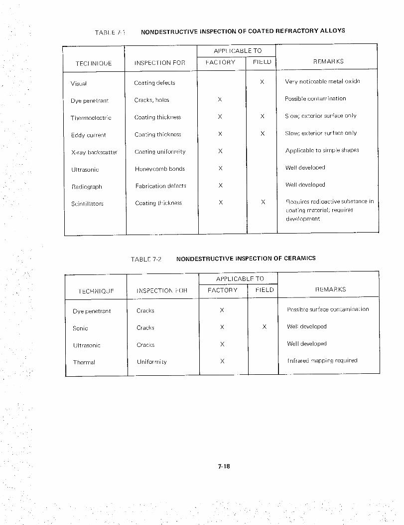
TABLE 7-1 NONDESTRUCTIVE INSPECTION OF COATED REFRACTORY ALLOYS
TECHNIQUE
Visual
Dye penetrant
Thermoelectric
Eddy current
X-ray backscatter
Ultrasonic
Radiograph
Scintillators
INSPECTION FOR
Coating defects
Cracks, holes
Coating thickness
Coating thickness
Coating uniformity
Honeycomb bonds
Fabrication defects
Coating thickness
APPLICABLE TO
FACTORY
X
X
X
X
X
X
X
FIELD
X
X
REMARKS
Very noticeable metal oxide
Possible contamination
Slow; exterior surface on ly
Slow; exterior surface only
Applicable to simple shapes
Well developed
Well developed
Requires radioactive substance in
coating material; requires
development
TABLE 7-2 NONDESTRUCTIVE INSPECTION OF CERAMICS
TECHNIQUE
Dye penetrant
Sonic
Ultrasonic
Thermal
INSPECTION FOR
Cracks
Cracks
Cracks
Uniformity
APPLICABLE TO
FACTORY
X
X
X
X
FIELD
X
REMARKS
Possible surface contamination
Well developed
Well developed
Infrared mapping required
7-18

TABLE7-3 NONDESTRUCTIVE INSPECTION OF COMPOSITES
TECHNIQUE
Resin matrix
Sonic
Ultrasonic
Radiography
Dielectric
Resistivity
Microwave
Thermal
Metal matrix
Sonic
Ultrasonic
Radiography
Thermal
INSPECTION FOR
Debonding, voids,
cracks
Debonding, voids,
cracks
Uniformity, voids
Moisture
Moisture
Resin cure
Uniformity
Debonding, voids,
cracks
Debonding, voids,
cracks
Uniformity, voids
Uniformity
APPLICABLE TO
FACTORY FIELD
X
X
X
X
X
X
X
X
X
X
X
X
X
X
REMARKS
Well developed
Well developed
Well developed
Principle developed
Principle developed
Frequency response is unknown;
complex equipment required
Infrared mapping required
Principle developed
Principle developed
Difficult in field
I nfrared mapping required
7-19

_ _i _,_-i_ii_I_i_ii, !__i_i¸¸I¸_¸¸_i iiii_iiii_iI _ I• " • _ " i _ • _ _r ¸ _ •

APPENDIX
CONVERSION OF U.S. CUSTOMARY UNITS TO SI UNITS
U.S.
CUSTOMARY
UNIT
foot
inch
knot
mph (miles per hour)
pound force
psf (pounds/foot 2)
psi (pounds/inch 2)
CONVERSION
FACTOR*
0.3048
0.0254
0.51479
0.447
4.448
47.8803
6894.757
SI UNIT
meter
meter
meter/second
meter/second
newton
newton/meter 2
newton/meter 2
* Multiply value given in U. S. customary unit by conversion factor to obtain equivalent value in SI unit.
A-1


