Periodic Table 2 Row, row, row…your element…gently through the periodic table?

Uludağ University Journal of The Faculty of Engineering, Vol. 25, No. 2, 2020 RESEARCH
DOI: 10.17482/uumfd.711022
1071
STRUCTURAL STRENGTHENING OF SECOND ROW
PASSENGER SEAT FRAME DEVELOPED FOR M1 CATEGORY
VEHICLES
Semih ERKUL*
Semih BALCI*
Received: 29.03.2020; accepted: 19.08.2020
Abstract: The issue of security in the automotive industry is becoming more and more important day by
day and intensive studies are carried out in this regard. It is vital that automobile seats have to meet security
regulations to assure optimum passenger safety. This article investigates the design changes of a passenger
seat required to meet and exceed the Economic Commission for Europe (ECE) R-14 regulation. ECE R-14
contains a lot of restrictions to secure adequate safety-belt anchorages endurance for vehicles. Various
design scenarios have been created to improve the performance of the seat. The CAD models have been
designed in CATIA V5 and validated using Hyperworks software. Then, physical tests were also conducted
with prototypes to compare outputs with FEA results.
Keywords: Second row passenger seat, tube to tube welding, safety-belt anchorages, frame integrity, ECE-
R14
M1 Kategorisi Araçlar İçin Geliştirilen İkinci Sıra Yolcu Koltuğu Karkasının Yapısal
Güçlendirilmesi
Öz: Otomotiv endüstrisinde güvenlik konusu her geçen gün daha da önem kazanmakta ve bu konuda yoğun
çalışmalar yapılmaktadır. Otomobil koltuklarının optimum yolcu güvenliğini sağlamak için güvenlik
yönetmeliklerini karşılaması çok önemlidir. Bu makale; Avrupa Ekonomik Komisyonu (ECE) R-14
yönetmeliği ile uyumlu ve bundan daha ağır şartlara da mukavemet göstermesi beklenen bir yolcu
koltuğunun tasarım değişikliklerini araştırmaktadır. ECE R-14, araçlarda yeterli emniyet kemeri ankraj
dayanımını sağlamak için birçok kısıtlama içerir. Koltuğun performansını arttırmak için farklı tasarım
senaryoları yaratılmıştır. CAD modelleri CATIA V5 kullanılarak tasarlanmış ve Hyperworks yazılımı
yardımıyla analiz edilmiştir. Ayrıca, FEA ve gerçek testlerin sonuçlarını karşılaştırmak için prototiplerle
fiziksel testler gerçekleştirilmiştir.
Anahtar Kelimeler: İkinci sıra yolcu koltuğu, borudan boruya kaynak, emniyet kemeri bağlantı
elemanları, karkas bütünlüğü, ECE-R14
* Diniz Adient Oto Donanım San. ve Tic A.Ş., Organize Sanayi Bölgesi Sarı Cad. No:25, 16159 Nilüfer, Bursa
İletişim Yazarı: Semih ERKUL ([email protected]), Semih BALCI ([email protected])

Erkul S.,Balcı S.: Strucl. Strghing. Of Second Row Passng. Seat Fram. Devlp. For M1 Cat. Vehicles
1072
1. INTRODUCTION
The automotive industry is consistently trying to decrease product development duration to
reduce the high costs and meet the customer demands. In addition, new regulations of
governments particularly focus on vehicle safety and there are some global regulations including
FMVSS (Federal Motor Vehicle Safety Standards) and ECE. The industry has to develop vehicles
to meet the ECE or FMVSS regulations and customer/industry demands as well. All these rules
continuously become harder due to increasing awareness on human and vehicle safety (Farahani
et al., 2002).
The appropriateness of seat belt anchorages for vehicles is inspected with ECE-R14
regulation. Physical tests are carried out and confirmation is provided for each seat within the
conditions written in the regulation, without considering whether the safety belt attachments are
positioned on BIW or seat. The following forces (See Table 1, 2 & 3) are exerted to the seat
depending on vehicle category using specific pulling equipments (UNECE, 2012).
There are different configurations of seat belt systems which are used in order to minimise
deaths and injuries caused by traffic accidents. The most common used of these structures are
three-point seat belts (Pişgin & Solmaz, 2018). Anchorages of this type can be only on the chassis
or there are different variations which they exist on the seat. In the systems with all support points
on the seat, it is aimed to increase the safety level with more effective seizing of passengers by
the seat belt.
Arslan and Kaptanoglu (2010) investigated to design the seat attachment brackets of different
seat types for a commercial vehicle. They aimed to meet ECE-R14 standard by conducting FEA
and physical tests for verification. Hessenberger (2003) researched on comparison of the two FEA
software in terms of the explicit and implicit analysis of seat belt anchorages. Then, he revealed
the advantages and disadvantages of them for evaluating. Shi and Xu (2018) discussed a seat
safety method which helps to meet the safety standards, besides reduces the development costs
and development period as increasing the physical test passing ratio. The exact pretreatment of
the front seat was conducted in HyperWorks software. Then, the model formula was solved in
LS-DYNA which showed the strength results of seat.
Table 1. Pulling forces applied to the two lower belt anchorages
M1 Category 22,250 N + 20 x the seat mass(kg) x 9.81 m/s2
M2 Category 11,100 N + 10 x the seat mass(kg) x 9.81 m/s2
M3 Category 7,400 N + 6.6 x the seat mass(kg) x 9.81 m/s2
Table 2. Pulling forces applied to the three-point belt anchorages (Lap / Pelvis block)
M1 Category 13,500 N + 20 x the seat mass(kg) x 9.81 m/s2
M2 Category 6,750 N + 10 x the seat mass(kg) x 9.81 m/s2
M3 Category 4,500 N + 6.6 x the seat mass(kg) x 9.81 m/s2
Table 3. Pulling forces applied to the three-point belt anchorages (Shoulder / Torso block)
M1 Category 13,500 N
M2 Category 6,750 N
M3 Category 4,500 N

Uludağ University Journal of The Faculty of Engineering, Vol. 25, No. 2, 2020
1073
The additional force calculations supplemented to the forces above represents the inertial
force of the seat. For example; in Table 2, M1 category (United Nations, 2017) pull force is
represented as 13,500 N + COG (Center of gravity) effect. In other words, it is a physical effect
of the seat mass to the relevant anchorages. This force can be applied onto the related parts of the
seat during test. Moreover; the extra load addition and load distribution should be decided by the
manufacturer. The technical team, which performs the test, should agree with it.
2. MATERIAL AND METHOD
First of all; in ECE-R14, the specified pulling forces have to be applied on test parts in the
fastest way. Although there is a maximum load application time of 60 seconds, the manufacturer
may request to complete the load application in 4 seconds. Then, the safety belt anchorages must
withstand the required load for not less than 0.2 second (UNECE, 2012).
After pulling the test specimen, permanent deformations and local ruptures or cracks on the
seat structure do not cause failing of the test. However; it is expected that the structure of safety
belt mechanism has to protect its rigidity and remain attached to the main body. In this study, the
customer did not accept any deformations or ruptures on the seat frame and this required stronger
metal frame rigidity.
In our physical tests, the both loads were arranged as 14850 N (Legal value + 10%).
Afterwards, they were increased to 16200 N (Legal value + 20%) to observe the seat structure
behavior in harder situations. Moreover, the seat should resist the loads more than 10 seconds
which is longer than legal duration.
2.1. Definition Of The Seat
The seat mentioned in the study is a second row passenger seat of an M1 category vehicle. It
was tested and simulated within the scope of product development activities. It is basically a 60/40
split-folding rear seat which offers 3 different folding options for users (60% part, %40 part and
both parts foldable), so that users are able to arrange the luggage and passenger positions in
several scenarios.
There are three seat belt anchorages for the seat. Two of them are body-connected type and
the other one is positioned on seat. Therefore, applied pull forces are directly transferred to the
seat and the BIW of vehicle through anchorages. There are five body attachment brackets used
for fixing the seat to the vehicle (See Figure 1).
Figure 1:
The image of second row seats created in 3D modeling software

Erkul S.,Balcı S.: Strucl. Strghing. Of Second Row Passng. Seat Fram. Devlp. For M1 Cat. Vehicles
1074
Material is a very important factor affecting the test performance. The material of frame tubes
was selected as DP800 steel to obtain appropriate formability without neglecting safety (See Table
4). Samples of DP800 material were subjected to tensile tests. As a result of tests; its yield
strength, tensile strength and elongation values as well as stress-strain curve were obtained. These
results were used for modelling material in FEA. The material thickness of frame tube was 1.5
mm.
Table 4. 800DP Steel Mechanical Properties
Material Name Minimum Yield Strength
(MPa)
Minimum Tensile
Strength (MPa) Elongation
DP800 575 875 %8
After determining the material properties, it was found out that frame tube elements cannot
have elongation value more than 8%.
3. DESIGN VERIFICATION PERIOD: FEA & PHYSICAL TESTS
Hypermesh and Hypercrash softwares were used to model finite elements and create
mathematical models as pre-processing. The pulling forces were calculated depending on the seat
weight. The safety belt coming from the belt anchorage on vehicle to the belt buckle isn’t modeled
due to having no impact on the seat structure in FEA. Because, these anchorages are on the BIW
of vehicle. All the forces related to seat (e.g. Torso Block, COG) were implemented to the FEA
models (See Figure 2), making 10 degree angle to X-axis in the median vehicle plane with ±5°
tolerance value. The mesh element sizes were arranged approximately as 5mm to obtain sufficient
results which are close to the physical tests.
Figure 2:
The Force-Time Graph of FEA Simulations
There are different types of elements used in the finite element modeling such as one-
dimensional (Rigid, Beam, Truss, Spring) elements, two-dimensional (Shell) elements and three-
dimensional elements (Tetra, Hexa) and their quantity is 114548 in total (See Table 5). Also, the
quantity of total nodes is 105551.

Uludağ University Journal of The Faculty of Engineering, Vol. 25, No. 2, 2020
1075
Seat frame as well as welds were modelled with shell elements, fasteners were modelled with
both beam and hexa elements. Lastly, safety belt was modelled with shell and truss elements.
Table 5. Mesh Elements Type & Quantities
Element Type Quantity
One-dimensional elements 564
Tria (2-D) 3420
Quad (2-D) 71094
Tetra (3-D) 21241
Hexa (3-D) 18229
The Figure 3 illustrates all the element types used for modeling. The mesh quality was
improved limiting tria elements amount up to 10% of quad elements.
Figure 3:
Element types used in FEA modeling software
The metal frame, which is the main model of FEA work, has a mesh structure quality created
according to the below standard (See Figure 4),
Figure 4:
The Quality Standards of Mesh Modeling
After all the necessary parameters were completed, models were solved using explicit method
in Radioss solver using a hardware which has 4-core, 2.9 GHz processor. First, the total energy
was compared with hourglass energy – 0 Joule in the study – to check the simulation accuracy in
terms of energy. The Figure 5 below shows the strain values obtained from the initial simulation.
Red elements having more than 8% plastic strain illustrate the undesirable behavior of the seat

Erkul S.,Balcı S.: Strucl. Strghing. Of Second Row Passng. Seat Fram. Devlp. For M1 Cat. Vehicles
1076
frame. This situation was especially seen at the tube to tube connection point of the 60% frame
structure (The right-hand part).
a. b.
Figure 5:
FEA Images of Triple Seat;
a. Simulated Elements on Tube to Tube Connection b. Plastic Strain Contour Plot
The first simulation result showed an unwanted behavior for the frame. But, the same sample
was modified changing the production parameters (e.g. weld settings) and subjected to simulation
again. Then, the test result was successful; however, it was very important to pass the test with a
stronger sample consistently without depending on production parameters. It was decided to
implement design improvements to the metal frame for obtaining more robust structure.
All the parts in FEA model comprise of isotropic elasto-plastic material. They use user-
defined functions for the work-hardening portion of the stress-strain curve at different strain rates
(Altair Engineering Inc., 2014).
In parallel, finite element works are generally supported with physical tests to check their
reliability. Therefore, the specific pulling test setup was prepared using the initial frame. As it is
seen in the Figure 6, the backrest of specimen does not include foam, but seat integrity still
provided.
a. b.
Figure 6:
Physical Test Setup of Initial Design;
a. Pre-Test Image b. Post-Test Image
There is a 1350 N pre-loading rule in the physical test before full loading. One of the biggest
difference in comparison to ECE-R14 is the standing time to force. The sample has to resist the

Uludağ University Journal of The Faculty of Engineering, Vol. 25, No. 2, 2020
1077
full loading period for ten seconds (See Table 6), whereas it is 0.2 second for ECE-R14. There
are two special apparatus to perform the test. They represent torso and pelvis of human body.
Table 6. The Initial Test Setup Document
Physical Safety Belt Anchorage Test Specifications
Actions Parameter
Loading Time
(Second) Force (Newton)
Percentage
(%)
Shoulder
Block
Lap
Block
COG
(40%
Seat)
COG
(60%
Seat)
Step Preload 1350 in total
1
Load
increase 1
14850 14850 1597 2719 110 (legal
+10%) Holding 1
2
Load
increase 1
16200 16200 1742 2967 120 (legal +
20%) Holding 10
3 Load
releasing 1 Down to 0%
The initial physical test was performed according to specifications above. The load
distribution applied to the seat was given in the Figure 7 depending on time.
Figure 7:
Load-Time Graph of Physical Pulling Test
Results were parallel to the FEA outputs. As it was mentioned before, there was an unwanted
situation in terms of seat integrity in case of not having optimum welding parameters.

Erkul S.,Balcı S.: Strucl. Strghing. Of Second Row Passng. Seat Fram. Devlp. For M1 Cat. Vehicles
1078
Additionally, one of the important factors was X-axis displacement value of center upper
anchorage. Although the X-displacement value of physical test was acceptable in terms of legal
ECE-R14, it was not suitable according to the harder specifications of customer. The displacement
behavior graph was given in the Figure 8. This graph was a result of frame vulnerability which
caused the decreasing of endurance against pulling forces, so that the upper seat area approached
towards pulling pistons more than expected.
Figure 8:
Effective Upper Anchorage X- Displacement Graph
These results were eliminated modifying the production parameters having the better quality.
However, both the simulation and the physical anchorage test demonstrated that there had to be a
more robust structure to pass the tests efficiently independent from other factors. Then, design
change studies were begun to improve the safety factor.
4. DESIGN VARIATIONS
Design changes were implemented to the dovetail region (Tube to Tube Connection) of the
60% frame. Because, the most vulnerability was clearly observed at this area after FEA and
physical tests. Four different types of wires were implemented to the initial version to obtain more
robust product using welding process. Some of them were showed in Figure 9.

Uludağ University Journal of The Faculty of Engineering, Vol. 25, No. 2, 2020
1079
Figure 9:
Different Formed Wire Implementation on Tube to Tube Connection
One of the wires was not feasible due to production difficulty and it was not mentioned in the
article. All the new designs were simulated in FEA with the same parameters conducted on the
initial design. One of the new approaches showed positive results (See Figure 10). It is a J-shape
wire consists of C18D steel. It has 8 mm diameter with 110 mm in length. The strain value did
not exceed 8% with this combination in FEA and this simulation presented a non-deformation
case.
Figure 10:
Strain Values of Modified Frames According to Wire Types
The frame supported with J-shape wire, was also physically tested to examine the similarity
with FEA simulation results. The same test setup was implemented according to the steps given
above (see Table 6).
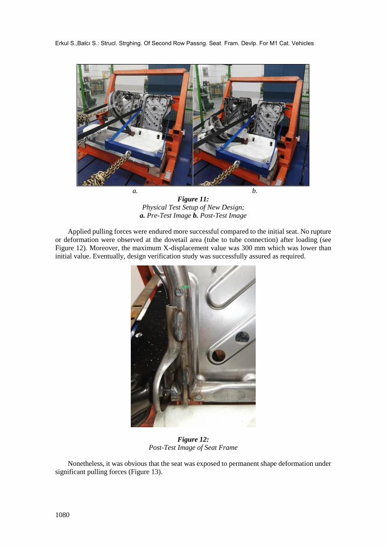
The Figure 11 below illustrates the pre-test and post-test visuals of seat frame supported with
J-shape wire.
Erkul S.,Balcı S.: Strucl. Strghing. Of Second Row Passng. Seat Fram. Devlp. For M1 Cat. Vehicles
1080
a. b.
Figure 11:
Physical Test Setup of New Design;
a. Pre-Test Image b. Post-Test Image
Applied pulling forces were endured more successful compared to the initial seat. No rupture
or deformation were observed at the dovetail area (tube to tube connection) after loading (see
Figure 12). Moreover, the maximum X-displacement value was 300 mm which was lower than
initial value. Eventually, design verification study was successfully assured as required.
Figure 12:
Post-Test Image of Seat Frame
Nonetheless, it was obvious that the seat was exposed to permanent shape deformation under
significant pulling forces (Figure 13).

Uludağ University Journal of The Faculty of Engineering, Vol. 25, No. 2, 2020
1081
a. b.
Figure 13:
Post-Test Deformations;
a. Seat Lock Mechanism b. Upper Center Seat Belt Anchorage
5. CONCLUSIONS
In conclusion, the previous existing design was able to withstand required forces with
optimum welding parameters, there was still a need of technical strengthening to improve the
safety factor.
As an output of this, pulling safety test activities were analysed within the company R&D
department and valuable know how was gained after lots of practice with FEA simulations. The
information was obtained about what amount of force severity could affect the seat and what kind
of improvement needed for that case with analyses.
Also, physical tests were practised. It was seen that there were very reliable results among
FEA and real tests in terms of expected deformation and displacement.
Finally; a second row triple passenger seat, which has better endurance to potential force,
was developed within the study. A three-point belt anchorage mechanism was implemented and
two of the anchorages were positioned on BIW, whereas the other one was located on the seat.
ACKNOWLEDGMENT
This work was prepared at Diniz Adient R&D department. Authors would like to thank for
facilities provided during the whole work period.
REFERENCES
1. Altair Engineering Inc. (2014), Hyperworks Release 13.0.0.
2. Arslan, A. ve Kaptanoğlu, M. (2010), Bir ticari araç için ECE R-14 regülasyonuna uygun
koltuk bağlantılarının geliştirilmesi, OTEKON 2010 5. Otomotiv Teknolojileri Kongresi.
3. Farahani, A., Tang, A., Palmer, T. & Uddin, Z. (2002), eta/VPG: A Virtual Crash and Safety
Environment for FMVSS and ECE Standards, 7th International LS-DYNA Conference
Crash/Safety (1).
4. Hessenberger, K. (2003), Strength Analysis of Seat Belt Anchorage According to ECE R14
and FMVSS, 4th European LS-DYNA Users Conference Crash / Automotive Applications II.

Erkul S.,Balcı S.: Strucl. Strghing. Of Second Row Passng. Seat Fram. Devlp. For M1 Cat. Vehicles
1082
5. Pişgin, E. & Solmaz, E. (2018), FMVSS 210 Normuna göre sürücü koltuğu geliştirilmesi,
Uludağ Üniversitesi Mühendislik Fakültesi Dergisi, Cilt 23, Sayı 1. Doi:
10.17482/uumfd.390068
6. Shi, P. & Xu, Z. (2018), Analysis of Seat Belt Anchorage Strength for Vehicles, IOP Conf.
Ser.: Mater. Sci. Eng. 301 012127, Doi: 10.1088/1757-899X/301/1/012127
7. UNECE (2012), Regulation No. 14 Uniform provisions concerning the approval of vehicles
with regard to safety-belt anchorages, ISOFIX anchorages systems and ISOFIX top tether
anchorages
8. United Nations (2017), Consolidated Resolution on the Construction of Vehicles (R.E.3).
ECE/TRANS/WP.29/78/Rev.6