Structural Resilience Policy and Details for Designing Village...
74
Partner Housing Australasia (Building) Incorporated - Structural Resilience Policy and Details for Designing Village Housing and Infrastructure in the South-Pacific for Wind, Earthquake and Tsunami P13111101-1b 25 November 2013 Rod Johnston Page 1 Structural Resilience Policy and Details for Designing Village Housing and Infrastructure in the South-Pacific for Wind, Earthquake and Tsunami PO Box 702, Pennant Hills NSW 1715 Phone: +61 4 0721 8926 Email: [email protected] Web: www.partnerhousing.org
Transcript of Structural Resilience Policy and Details for Designing Village...

Partner Housing Australasia (Building) Incorporated - Structural Resilience Policy and Details for Designing Village Housing and Infrastructure in the South-Pacific for Wind, Earthquake and Tsunami
P13111101-1b 25 November 2013 Rod Johnston Page 1
Structural Resilience Policy and Details
for Designing Village Housing and Infrastructure
in the South-Pacific
for Wind, Earthquake and Tsunami
PO Box 702, Pennant Hills NSW 1715 Phone: +61 4 0721 8926 Email: [email protected] Web: www.partnerhousing.org

Partner Housing Australasia (Building) Incorporated - Structural Resilience Policy and Details for Designing Village Housing and Infrastructure in the South-Pacific for Wind, Earthquake and Tsunami
P13111101-1b 25 November 2013 Rod Johnston Page 2
Contents
Executive Summary ........................................................................................................... 4
Part 1 – Structural Design Policy ..................................................................................... 5
Background .......................................................................................................................... 5
Countries Covered by This Policy ........................................................................................ 5
Policy Where Building Regulations are Enforced ................................................................. 5
Policy for Small Buildings where Building Regulations are Not Enforced ............................ 6
Notes on Annual Probability of Exceedance ........................................................................ 7
Notes on Load Combinations ............................................................................................... 8
Notes on Permanent Loads ................................................................................................. 9
Notes on Imposed Loads ................................................................................................... 10
Notes on Wind Loads......................................................................................................... 10
Notes on Earthquake Loads .............................................................................................. 16
Notes on Tsunami Loads ................................................................................................... 25
Notes on Flood Loads ........................................................................................................ 26
Notes on Soil Properties .................................................................................................... 27
Part 2 - References .......................................................................................................... 29
Scope................................................................................................................................. 29
Building Acts and Building Regulations – South Pacific ..................................................... 29
Load Combinations, Permanent Loads, Imposed Loads ................................................... 31
Wind................................................................................................................................... 31
Earthquakes ....................................................................................................................... 31
Tsunamis and Floods ......................................................................................................... 32
Soil Load and Movement ................................................................................................... 32
General References ........................................................................................................... 32
Part 3 – Country Design and Analysis Assumptions .......................................................... 33
Scope................................................................................................................................. 33
Details ................................................................................................................................ 33
Australia ............................................................................................................................. 34
Cook Islands ...................................................................................................................... 35
Fiji ...................................................................................................................................... 36
French Polynesia ............................................................................................................... 37
Kiribati ................................................................................................................................ 38
Nauru ................................................................................................................................. 39
New Caledonia .................................................................................................................. 40
New Zealand ...................................................................................................................... 41

Partner Housing Australasia (Building) Incorporated - Structural Resilience Policy and Details for Designing Village Housing and Infrastructure in the South-Pacific for Wind, Earthquake and Tsunami
P13111101-1b 25 November 2013 Rod Johnston Page 3
Niue ................................................................................................................................... 42
Papua New Guinea ............................................................................................................ 43
Samoa ............................................................................................................................... 44
American Samoa ............................................................................................................... 45
Solomon Islands ................................................................................................................ 46
Tonga ................................................................................................................................. 47
Tuvalu ................................................................................................................................ 48
Vanuatu .............................................................................................................................. 49
Wallis and Futuna .............................................................................................................. 50
Part 4 – Bracing, Anchorage and Connection Details .................................................. 51
Scope................................................................................................................................. 51
Bracing, Anchorage and Connection Details ...................................................................... 51
Braced Post ....................................................................................................................... 52
Braced Post ....................................................................................................................... 53
Unbraced Post ................................................................................................................... 54
Unbraced Post ................................................................................................................... 55
Sub-floor Tension Bracing .................................................................................................. 56
Sub-floor Tension Bracing .................................................................................................. 57
Sub-floor Compression Bracing ......................................................................................... 58
Wall Bracing ....................................................................................................................... 59
Wall Bracing ....................................................................................................................... 60
Wall Bracing ....................................................................................................................... 61
Wall Bracing ....................................................................................................................... 62
Wall Bracing ....................................................................................................................... 63
Roof Framing Fixings ......................................................................................................... 64
Roof Batten Fixing ............................................................................................................. 65
Roof Batten Fixing ............................................................................................................. 66
Roof Batten Fixing ............................................................................................................. 67
Roof Fixings and Cyclone Washers ................................................................................... 68
“Fishtail” Roof Anchors for Reinforced Concrete Masonry Bond Beams ........................... 69
“Single” Roof Anchors for Reinforced Concrete Masonry Bond Beams ............................ 70
Appendix 1 – Cyclone Categories .................................................................................. 71
Appendix 2 – Worked Example ......................................... Error! Bookmark not defined.
Appendix 3 – Regional Loads ........................................... Error! Bookmark not defined.

Partner Housing Australasia (Building) Incorporated - Structural Resilience Policy and Details for Designing Village Housing and Infrastructure in the South-Pacific for Wind, Earthquake and Tsunami
P13111101-1b 25 November 2013 Rod Johnston Page 4
Executive Summary
Background
In cities of the South Pacific region, structural design and construction generally follow established building regulations and design standards. However, village housing and infrastructure in developing countries often incorporate traditional materials and detailing, which do not necessarily have the structural resilience implicit in modern regulations.
Part 1 – Structural Design Policy
Policy Where Building Regulations are Enforced
In those locations where building regulations are enacted and routinely enforced, design and construction should adhere to those regulations. For example, construction in cities and in developed countries should adhere to local building regulations.
Policy Where Building Regulations are Not Enacted, Unclear or Not Routinely Enforced
This policy applies only to small detached village buildings (such as houses and small community buildings), presenting a low degree of hazard to life and other property in case of failure. It applies only to single storey buildings, with cladding on elevated braced timber frames, or to reinforced concrete masonry buildings built on concrete slab-on-ground. The maximum dimensions of such buildings shall not exceed 12.5 m x 8.0 m, 2.7 m storey height, maximum eaves height 6.0 m, maximum ridge height 8.5 m, and maximum pitch 35
o.
The intended design life shall not be less than 25 years. The policy deals with:
Design for Ultimate Limit State, based on an Annual Probability of Exceedance of 1 in 250
Load Combinations
Permanent Loads
Imposed Loads
Wind Loads
Earthquake Loads
Tsunami Loads
Flood Loads
Soil properties.
Part 2 - References
This part provides references to various regulations, standards and papers, which have been used in the preparation of this manual.
Part 3 – Country Design and Analysis Assumptions
This part provides the design and analysis assumptions for small detached village buildings (such as houses and small community buildings) in each of the countries covered by this manual, taking account of the location, proximity to cyclonic wind zones, proximity to high earthquake areas and plate boundaries, typical topography and susceptibility to tsunamis.
Part 4 – Default Details
This part provides typical details, together with the calculated capacities, which can be selected to cater for the loads on houses and village infrastructure that are calculated using Part 4 of this manual.
Appendix 1 – Regional Loads
This Appendix sets out design loads for houses and village infrastructure in particular locations within the South Pacific region. It translates the broad country-based design and analysis assumptions of Part 3 into design loads relevant to particular locations within those countries.
Partner Housing Australasia (Building) Incorporated - Structural Resilience Policy and Details for Designing Village Housing and Infrastructure in the South-Pacific for Wind, Earthquake and Tsunami
P13111101-1b 25 November 2013 Rod Johnston Page 5
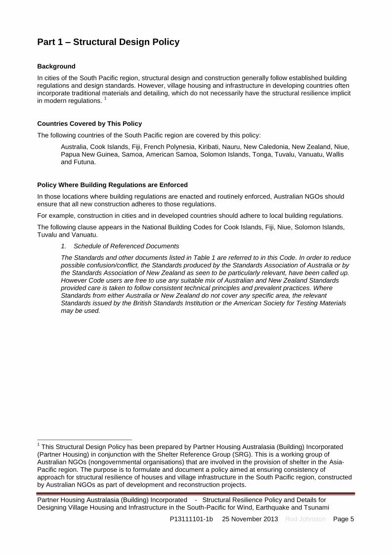
Part 1 – Structural Design Policy
Background
In cities of the South Pacific region, structural design and construction generally follow established building regulations and design standards. However, village housing and infrastructure in developing countries often incorporate traditional materials and detailing, which do not necessarily have the structural resilience implicit in modern regulations.
1
Countries Covered by This Policy
The following countries of the South Pacific region are covered by this policy:
Australia, Cook Islands, Fiji, French Polynesia, Kiribati, Nauru, New Caledonia, New Zealand, Niue, Papua New Guinea, Samoa, American Samoa, Solomon Islands, Tonga, Tuvalu, Vanuatu, Wallis and Futuna.
Policy Where Building Regulations are Enforced
In those locations where building regulations are enacted and routinely enforced, Australian NGOs should ensure that all new construction adheres to those regulations.
For example, construction in cities and in developed countries should adhere to local building regulations.
The following clause appears in the National Building Codes for Cook Islands, Fiji, Niue, Solomon Islands, Tuvalu and Vanuatu.
1. Schedule of Referenced Documents
The Standards and other documents listed in Table 1 are referred to in this Code. In order to reduce possible confusion/conflict, the Standards produced by the Standards Association of Australia or by the Standards Association of New Zealand as seen to be particularly relevant, have been called up. However Code users are free to use any suitable mix of Australian and New Zealand Standards provided care is taken to follow consistent technical principles and prevalent practices. Where Standards from either Australia or New Zealand do not cover any specific area, the relevant Standards issued by the British Standards Institution or the American Society for Testing Materials may be used.
1 This Structural Design Policy has been prepared by Partner Housing Australasia (Building) Incorporated
(Partner Housing) in conjunction with the Shelter Reference Group (SRG). This is a working group of Australian NGOs (nongovernmental organisations) that are involved in the provision of shelter in the Asia-Pacific region. The purpose is to formulate and document a policy aimed at ensuring consistency of approach for structural resilience of houses and village infrastructure in the South Pacific region, constructed by Australian NGOs as part of development and reconstruction projects.

Partner Housing Australasia (Building) Incorporated - Structural Resilience Policy and Details for Designing Village Housing and Infrastructure in the South-Pacific for Wind, Earthquake and Tsunami
P13111101-1b 25 November 2013 Rod Johnston Page 6
Policy for Small Buildings where Building Regulations are Not Enforced
This policy applies only to small detached village buildings (such as houses and small community buildings), presenting a low degree of hazard to life and other property in case of failure.
It applies only to single storey buildings, with cladding on elevated braced timber frame or to reinforced concrete masonry buildings built on concrete slab-on-ground.
The maximum dimensions of such buildings shall not exceed 12.5 m x 8.0 m, 2.7 m storey height, maximum eaves height 6.0 m, maximum ridge height 8.5 m, and maximum pitch 35
o.
The intended design life shall not be less than 25 years.
Unless specifically over-ridden by existing in-country building regulations, requirements shall be interpreted in the light of the most recent Australian and Australian/New Zealand Standards listed below.
Design for Ultimate Limit State – Annual Probability of Exceedance is 1 in 250. Reference Period (design life) is 25 years, leading to a probability of exceedance during the life of 0.10. Load factors (applied to the representative loads) and capacity reduction factors (applied to a specified “lower 5 percentile” characteristic strengths of components) shall ensure that the probability of failure is “low” (e.g. Target Reliability Index β = 3.1)
Load Combinations– As per AS/NZS 1170.0
Permanent Loads – As per AS/NZS 1170.1
Imposed Loads – As per AS/NZS 1170.1
Wind Loads – Analysis as per AS 4055, using wind speeds from the relevant Building Regulations or, if appropriate, HB 212
Earthquake Loads – Analysis assumptions set out in AS 1170.4, EDC II, using hazard factors appropriate to the region
Tsunami Loads – For structures that are required to be designed for tsunami (except those that should be moved), analysis shall be in accordance with using the method in Australian Building Codes Board Handbook, Construction of Buildings in Flood Hazard Areas for a velocity of 1.5 m/s. Structural components shall be designed to withstand the design event, assuming that the cladding is partially destroyed.
Flood Loads – For structures that are required to be designed for flood (except those that should be moved), analysis shall be in accordance with using the method in Australian Building Codes Board Handbook, Construction of Buildings in Flood Hazard Areas for a velocity of 1.5 m/s. Structural components shall be designed to withstand the design event, assuming that the cladding remains intact.
Soil Properties – Site classification, construction and analysis to AS 2870; Soil loads to AS 4678
Similar to the situation where the “Building Regulations are enforced” the following clause (from the National Building Codes for Cook Islands, Fiji, Niue, Solomon Islands, Tuvalu and Vanuatu) shall be deemed applicable.
1. Schedule of Referenced Documents
The Standards and other documents listed in Table 1 are referred to in this Code. In order to reduce possible confusion/conflict, the Standards produced by the Standards Association of Australia or by the Standards Association of New Zealand as seen to be particularly relevant, have been called up. However Code users are free to use any suitable mix of Australian and New Zealand Standards provided care is taken to follow consistent technical principles and prevalent practices. Where Standards from either Australia or New Zealand do not cover any specific area, the relevant Standards issued by the British Standards Institution or the American Society for Testing Materials may be used.

Partner Housing Australasia (Building) Incorporated - Structural Resilience Policy and Details for Designing Village Housing and Infrastructure in the South-Pacific for Wind, Earthquake and Tsunami
P13111101-1b 25 November 2013 Rod Johnston Page 7
Notes on Annual Probability of Exceedance
Australia and New Zealand
The Australian National Construction Code BCA Volume Two Table 3.11.3a defines Importance Level 2 as “Buildings or structures not included in Importance Level 1 [Buildings or structures presenting a low degree of hazard to life and other property in case of failure]”.
In Australia, houses and small buildings with an Importance Level of 2 must be designed for an Annual Probability of Exceedance for wind loads and earthquake loads of 1 : 500.
The Building Regulations require the capacity to be based on the “lower 5 percentile” characteristic strengths of components) but do not regulate the probability of failure.
The approach in New Zealand is similar, except that cyclonic winds do not apply, and there is significantly more emphasis on earthquake loads.
Other South Pacific Countries
Section 2 of this policy applies only to small detached village buildings (such as houses and small community buildings). It is further limited to single storey buildings, with cladding on elevated braced timber frame, or to reinforced concrete masonry buildings built on concrete slab-on-ground. The maximum dimensions of such buildings shall not exceed 12.5 m x 8.0 m, 2.7 m storey height, maximum eaves height 6.0 m, maximum ridge height 8.5 m, and maximum pitch 35
o.
Such buildings are deemed to “present a low degree of hazard to life and other property in case of failure”.
Based on the above-mentioned limitations, an Annual Probability of Exceedance of 1 in 250 has been selected for design for Ultimate Limit State.
These small, single storey houses are (in general) considerably smaller than most new houses in Australia and New Zealand. Further, the likely design life will also probably much shorter. A design life “not exceeding 25 years” has been selected.
The Reference Period (design life) of 25 years for 1 in 250 leads to a probability of exceedance during the life of 0.10.
This manual seeks to achieve consistency of approach when dealing with various loads; in particular wind and earthquake loads. To achieve this the basic variables (3 second wind gust speed at a height of 10 m and earthquake hazard) are determined and reported for a Probability of Exceedance of 1 : 500. A factor, kp, is then applied to the resulting forces, after (in the case of wind) provision has been made for terrain category, shielding, topography and pressure/suction factors.
Annual Probability of Exceedance
Application Probability Factor, kp
Earthquake Loads
AS 1170.4 Table 3.1
AS/NZS 1170.2 and HB 212
1 : 500 Ultimate limit state in Australia, New Zealand and places where 1 : 500 is regulated
1.0 1.0
1 : 250 Ultimate limit state in villages where 1 : 500 is not regulated
0.75 Zone I 0.90
Zone II 0.91
Zone III 0.86
Zone IV 0.88
Zone V 0.86
1 : 50 Serviceability in villages where 1 : 500 is not regulated
0.35 Zone I 0.64
Zone II 0.75
Zone III 0.60
Zone IV 0.62

Partner Housing Australasia (Building) Incorporated - Structural Resilience Policy and Details for Designing Village Housing and Infrastructure in the South-Pacific for Wind, Earthquake and Tsunami
P13111101-1b 25 November 2013 Rod Johnston Page 8
Zone V 0.66
Notes on Load Combinations
Australia and New Zealand
Australia and New Zealand Building Regulations call up the 2002 version (with amendments) of AS/NZS 1170.0:2002, which includes formulae for load combinations. This includes a combination factor of 1.2 on permanent loads (in combination with imposed loads), rather than the value of 1.25 in the earlier 1989 standard.
Other South Pacific Countries
The 2002 version (with amendments) of AS/NZS 1170.0:2002, including the combination factor of 1.2, is used in this “Policy for Small Buildings where Building Regulations are Not Enforced”, although some other countries do not specifically refer to them.

Partner Housing Australasia (Building) Incorporated - Structural Resilience Policy and Details for Designing Village Housing and Infrastructure in the South-Pacific for Wind, Earthquake and Tsunami
P13111101-1b 25 November 2013 Rod Johnston Page 9
Notes on Permanent Loads
The 2002 version (with amendments) of AS/NZS 1170.1:2002 is used in this policy to determine permanent loads, although some other countries do not specifically refer to it.
In providing default values for standard calculations, the following permanent loads of particular components (expressed as kN / m
2 of plan footprint area) have been assumed.
Surface Weight of Components of Timber Framed Houses
Surface weight of roof sheeting 0.080 kN/m2
Surface weight of roof battens 0.037 kN/m2
Surface weight of roof framing 0.135 kN/m2
Surface weight of ceiling battens 0.033 kN/m2
Surface weight of ceiling lining 0.076 kN/m2
Surface weight of external wall cladding 0.215 kN/m2
Surface weight of external wall framing 0.167 kN/m2
Surface weight of external wall lining 0.076 kN/m2
Surface weight of internal wall framing 0.167 kN/m2
Surface weight of internal wall lining 0.260 kN/m2
Surface weight of floor sheeting 0.220 kN/m2
Surface weight of floor Joists 0.138 kN/m2
Surface weight of floor bearers 0.092 kN/m2
Surface weight of subfloor posts 0.183 kN/m2
Surface weight of sub-floor bracing 0.014 kN/m2
Surface weight of steps 0.748 kN/m2
Surface weight of windows 0.150 kN/m2
Surface weight of doors 0.330 kN/m2
Surface Weight of Components of Reinforced Concrete Masonry Houses
Surface weight of roof sheeting 0.080 kN/m2
Surface weight of roof battens 0.037 kN/m2
Surface weight of roof framing 0.135 kN/m2
Surface weight of ceiling battens 0.033 kN/m2
Surface weight of ceiling lining 0.076 kN/m2
Surface weight of external wall cladding 2.158 kN/m2
Surface weight of internal wall framing 0.167 kN/m2
Surface weight of internal wall lining 0.260 kN/m2
Surface weight of windows 0.150 kN/m2
Surface weight of doors 0.330 kN/m2
The permanent loads should be calculated for each building, although, for small detached village buildings, the following default permanent loads acting at floor level may be used.
Elevated timber building, w = 2.0 kN/m2 (of plan footprint area),
Reinforced masonry building w = 3.0 kN/m2 (of plan footprint area)

Partner Housing Australasia (Building) Incorporated - Structural Resilience Policy and Details for Designing Village Housing and Infrastructure in the South-Pacific for Wind, Earthquake and Tsunami
P13111101-1b 25 November 2013 Rod Johnston Page 10
Notes on Imposed Loads
The 2002 version (with amendments) of AS/NZS 1170.1:2002 is used in this policy to determine imposed loads, although some other countries do not specifically refer to them.
In particular, for small detached village buildings, an imposed floor load of 1.5 kPa and an imposed roof load of 0.25 kPa are used.
Notes on Wind Loads
Basic wind speeds shall be determined in accordance with the following map and table, except where overridden by more recent Australian or New Zealand Standards.
Reference: Standards Australia Handbook HB 212:2002

Partner Housing Australasia (Building) Incorporated - Structural Resilience Policy and Details for Designing Village Housing and Infrastructure in the South-Pacific for Wind, Earthquake and Tsunami
P13111101-1b 25 November 2013 Rod Johnston Page 11
This manual seeks to achieve consistency of approach when dealing with various loads; in particular wind and earthquake loads.
To achieve this the basic variable (3 second wind gust speed at a height of 10 m) is determined and reported for a Probability of Exceedance of 1 : 500.
A factor, kp, is then applied to the resulting forces, after provision has been made for terrain category, shielding topography and pressure/suction factors. Noncyclonic Level I Vu 500 (3,10) = 40 m/s kp 250 = 0.90 Noncyclonic Level II (A) Vu 500 (3,10) = 45 m/s kp 250 = 0.91 Noncyclonic Level III (B) Vu 500 (3,10) = 57 m/s kp 250 = 0.86 Cyclonic Level IV (C) Vu 500( 3,10) = 66 m/s kp 250 = 0.88 Cyclonic Level V (D) Vu 500 (3,10) = 80 m/s kp 250 = 0.86 Noncyclonic Level III (W) Vu 500( 3,10) = 51 m/s kp 250 = 0.92
Wind Categories Description Equation Vu 500 (3,10)
m/s
Vu 250 (3,10)
m/s kp 250
Zone I - Pacific islands adjacent to the equator, East Timor,
Papua New Guinea, Solomon Islands , Indonesia, Malaysia,
Singapore, Inland Karnataka (India),
Strong thunderstorms
and monsoon winds 70 - 56 R -0.1 40 38 0.90
Zone II (A) - South-west tip of Papua New Guinea, most of
southern India, western Indial coastal strip (Mumbai, inland
Madhya Pradesh, Orissa), western Mindanao,
Australia & New Zealand Zones A1-A7(Southern & inland)
Moderately severe
thunderstorms and
extra-tropical gales
67 - 41 R -0.1 45 43 0.91
Zone III (B) - Coastal strips of Tamil Nadu (including
Chennai), Andhra Pradesh, Orissa, Gujaret, West Bengal
(including Calcutta), Assam, northern India (inclusing Delhi),
central Tamil Nadu, Eastern Mindanao, Palawan(Philippines)
Australia Zone B (South-east Queensland)
Severe thunderstorms
and moderate or
weakening typhoons or
tropical cyclones
106 - 92 R -0.1 57 53 0.86
Zone IV (C) - Pacific Islands below 6oS, Tripiura & Mizoram,
Ladakh (India), remainder of Philippines
Australia Zone C (Northern coast)
Strong typhoons or
tropical cyclones FC (122 - 104 R -0.1) 66 62 0.88
Zone V (D) - Eastern Luzon (Philippines)
Australia Zone D (West coast)
Very strong typhoons
or tropical cyclonesFD (156 - 142 R -0.1) 80 74 0.86
Zone W New Zealand Wellington Region 104 - 70 R -0.045 51 49 0.92
Notes
1.Wind speeds are for a 3 second gust, at 10 m height in open country terrain.
2. For R < 50 years, Fc abd Fd = 1.0
3.Sources: HB 212 Design wind speeds for the Asia-Pacific Region , 2002 and AS/NZS 1170.2:2011; Standards Australia
4. Pink shaded areas are for 1 : 500 Probability of Exceedance (e.g. Housing in Australia and New Zealand).
5. Blue shaded areas are for 1 : 250 Probability of Exceedance (e.g. Village housing in developing countries).
6. Probability Factor, kp = (Vu 500 (3,10) / Vu 500 (3,10))2, and is applied to resulting pressures, suctions and forces.

Partner Housing Australasia (Building) Incorporated - Structural Resilience Policy and Details for Designing Village Housing and Infrastructure in the South-Pacific for Wind, Earthquake and Tsunami
P13111101-1b 25 November 2013 Rod Johnston Page 12
The relevant Wind Classifications (N1 to N6 or C1 to C4) are calculated using AS 4055 from the Basic Wind Speeds (for a 3 second gust at a height of 10 m in open terrain [TC 2]), taking account of the terrain category, shielding and topography.
The following table is based on AS 4055 Table 2.2.
Wind Classifications
Region Terrain
Category
Topographic classification
T0 T1 T2 T3 T4 T5
FS PS NS FS PS NS FS PS NS PS NS NS NS
I
3 N1 N1 N1 N1 N1 N1 N1 N1 N1 N2 N2 N2 N2 2.5 N1 N1 N1 N1 N1 N1 N1 N2 N2 N2 N2 N3 N3 2 N1 N1 N1 N1 N1 N2 N1 N2 N2 N2 N2 N3 N3
1.5 N1 N1 N1 N1 N1 N2 N2 N2 N2 N2 N3 N3 N3 1 N1 N2 N2 N1 N2 N2 N2 N2 N3 N3 N3 N3 N4
II (A)
3 N1 N1 N1 N1 N2 N2 N2 N2 N2 N3 N3 N3 N3 2.5 N1 N1 N2 N1 N2 N2 N2 N3 N3 N3 N3 N4 N4 2 N1 N2 N2 N2 N2 N3 N2 N3 N3 N3 N3 N4 N4
1.5 N2 N2 N2 N2 N3 N3 N3 N3 N3 N3 N4 N4 N4 1 N2 N3 N3 N2 N3 N3 N3 N3 N4 N4 N4 N4 N5
III (B)
3 N2 N2 N3 N2 N3 N3 N3 N3 N4 N4 N4 N5 N5 2.5 N2 N3 N3 N3 N3 N3 N3 N4 N4 N4 N4 N5 N5 2 N2 N3 N3 N3 N3 N4 N3 N4 N4 N4 N5 N5 N5
1.5 N3 N3 N4 N3 N4 N4 N4 N4 N4 N5 N5 N5 N6 1 N3 N4 N4 N4 N4 N4 N4 N5 N5 N5 N5 N6 N6
IV (C)
3 C1 C1 C2 C1 C2 C2 C2 C2 C3 C3 C3 C3 C4 2.5 C1 C2 C2 C2 C2 C2 C2 C3 C3 C3 C3 C4 2 C1 C2 C2 C2 C2 C3 C2 C3 C3 C3 C4 C4
1.5 C2 C2 C3 C2 C3 C3 C3 C3 C4 C4 C4 1 C2 C3 C3 C3 C3 C3 C3 C4 C4 C4
V (D)
3 C2 C3 C3 C2 C3 C3 C3 C4 C4 C4 C4 2.5 C2 C3 C3 C3 C3 C4 C3 C4 C4 C4 2 C3 C3 C4 C3 C4 C4 C4 C4
1.5 C3 C4 C4 C4 C4 C4 1 C3 C4 C4 C4
Notes:
1. This table is derived from AS 4055 Table 2.2.
2. The wind classifications for Region I have been determined by extrapolation from Region II.
3. Regions are defined as in HB212.
4. AS/NZS 1170.2 and AS 4055 regions (A, B, C and D) have been indicated in brackets.
5. Region W has been omitted for clarity. It may be conservatively taken as the same as Region III.
6. FS = full shielding PS = partial shielding NS = no shielding
7. The classification shown in large bold red lettering are those taken as defaults in the following data

Partner Housing Australasia (Building) Incorporated - Structural Resilience Policy and Details for Designing Village Housing and Infrastructure in the South-Pacific for Wind, Earthquake and Tsunami
P13111101-1b 25 November 2013 Rod Johnston Page 13
For Annual Probability of Exceedance 1 : 500 (Including Australia and New Zealand)
The Australian National Construction Code BCA Volume Two refers to AS/NZS 1170.2:2011(Including Amendments 1 and 2) and to AS 4055:2012.
The New Zealand building regulations refer to AS/NZS 1170.2:2011(Including Amendments 1 and 2. #
The design of houses and residential infrastructure in Australia and New Zealand shall be based on wind loads with a probability of Exceedance of 1 : 500.
The corresponding basic wind pressures, derived from AS 4055 for 1 : 500 (used for Australia and New Zealand) are:
Non-cyclonic Wind Level N1 Vh,u 500 (3,6.5) = 34 m/s; kp = 1.0 qu = 0.69 kPa
Non-cyclonic Wind Level N2 Vh,u 500 (3,6.5) = 40 m/s; kp = 1.0 qu = 0.96 kPa
Non-cyclonic Wind Level N3 Vh,u 500 (3,6.5) = 50 m/s; kp = 1.0 qu = 1.50 kPa
Non-cyclonic Wind Level N4 Vh,u 500 (3,6.5) = 61 m/s; kp = 1.0 qu = 2.23 kPa
Non-cyclonic Wind Level N5 Vh,u 500 (3,6.5) = 74 m/s; kp = 1.0 qu = 3.29 kPa
Non-cyclonic Wind Level N6 Vh,u 500 (3,6.5) = 86 m/s; kp = 1.0 qu = 4.44 kPa
Cyclonic Wind Level C1 Vh,u 500 (3,6.5) = 50 m/s; kp = 1.0 qu = 1.50 kPa
Cyclonic Wind Level C2 Vh,u 500 (3,6.5) = 61 m/s; kp = 1.0 qu = 2.23 kPa
Cyclonic Wind Level C3 Vh,u 500 (3,6.5) = 74 m/s; kp = 1.0 qu = 3.29 kPa
Cyclonic Wind Level C4 Vh,u 500 (3,6.5) = 86 m/s; kp = 1.0 qu = 4.44 kPa
For Annual Probability of Exceedance 1 : 250
This “Policy for Small Buildings where Building Regulations are Not Enforced” applies only to small detached village buildings (such as houses and small community buildings). It is further limited to single storey buildings, with cladding on elevated braced timber frame or reinforced concrete masonry buildings built on concrete slab-on-ground. The maximum dimensions of such buildings shall not exceed 12.5 m x 8.0 m, 2.7 m storey height, maximum eaves height 6.0 m, maximum ridge height 8.5 m, and maximum pitch 35
o.
The design of village houses and infrastructure in this situation may be based on wind loads with a probability of Exceedance of 1 : 250.
The corresponding basic wind pressures, extrapolated from AS 4055 for 1 : 250 (used for other countries) are:
Non-cyclonic Wind Level N1 Vh,u 500 (3,6.5) = 34 m/s; kp = 0.90 qu = 0.62 kPa
Non-cyclonic Wind Level N2 Vh,u 500 (3,6.5) = 40 m/s; kp = 0.90 qu = 0.86 kPa
Non-cyclonic Wind Level N3 Vh,u 500 (3,6.5) = 50 m/s; kp = 0.90 qu = 1.35 kPa
Non-cyclonic Wind Level N4 Vh,u 500 (3,6.5) = 61 m/s; kp = 0.90 qu = 2.01 kPa
Non-cyclonic Wind Level N5 Vh,u 500 (3,6.5) = 74 m/s; kp = 0.90 qu = 2.96 kPa
Non-cyclonic Wind Level N6 Vh,u 500 (3,6.5) = 86 m/s; kp = 0.90 qu = 3.99 kPa
Cyclonic Wind Level C1 Vh,u 500 (3,6.5) = 50 m/s; kp = 0.88 qu = 1.32 kPa
Cyclonic Wind Level C2 Vh,u 500 (3,6.5) = 61 m/s; kp = 0.88 qu = 1.96 kPa
Cyclonic Wind Level C3 Vh,u 500 (3,6.5) = 74 m/s; kp = 0.88 qu = 2.89 kPa
Cyclonic Wind Level C4 Vh,u 500 (3,6.5) = 86 m/s; kp = 0.88 qu = 3.91 kPa

Partner Housing Australasia (Building) Incorporated - Structural Resilience Policy and Details for Designing Village Housing and Infrastructure in the South-Pacific for Wind, Earthquake and Tsunami
P13111101-1b 25 November 2013 Rod Johnston Page 14
Some national building codes call up AS 1170.2:1989, which was in place at the time that the regulations were drafted. They also refer to the permissible stress method of design.
However, this “Policy for Small Buildings where Building Regulations are Not Enforced” provides ultimate limit state loads, based on the following assumptions:
Analysis shall be consistent with AS 4055, except as follows.
Basic wind speeds shall be determined from the relevant Building Regulations or, if appropriate, HB 212 factored to achieve a Probability of Exceedance of 1 : 250.
Terrain category, shielding and topography should be assessed for each particular site. Default values, accounting for the location, basic wind speed, most common terrain, typical topography and partial shielding, are provided in Part 3 of this manual to give guidance.
AS/NSZ 1170.2 and HB212 require the calculated value of VR to be rounded to the nearest 1 m/s.
HB 212 states, “The basic wind speed, VR, ….. is 3 s gust at 10 m height in flat open country terrain.
The Terrain/Height Multiplier, Mz,cat, for a height of 8 m and Terrain Category 2 is 0.985.
Calculation of Pressures
Pressure calculation is as follows:
p = kp (0.5 ρair) [Vh]2 Cp
Where
p = Design wind pressure acting normal to a surface (Pascals)
Pressures are taken as positive, indicating pressures above ambient and negative, indicating pressures below ambient.
kp = Probability factor (to account for changed Probability of Exceedance)
ρair = Density of air, taken as 1.2 kg/m3
Vh = Design 3 second gust wind speed
Cp = Pressure coefficient (External, internal or net, as appropriate)

Partner Housing Australasia (Building) Incorporated - Structural Resilience Policy and Details for Designing Village Housing and Infrastructure in the South-Pacific for Wind, Earthquake and Tsunami
P13111101-1b 25 November 2013 Rod Johnston Page 15

Partner Housing Australasia (Building) Incorporated - Structural Resilience Policy and Details for Designing Village Housing and Infrastructure in the South-Pacific for Wind, Earthquake and Tsunami
P13111101-1b 25 November 2013 Rod Johnston Page 16
Papua New Guinea
Reference: Papua New Guinea Building Regulation 1994
Notes on Earthquake Loads
Australia
The Australian National Construction Code BCA Volume Two refers to AS 1170.4:2007. The design of houses and infrastructure in Australia shall be based on earthquake loads with a Probability of Exceedance of 1 : 500.
Peak Ground Acceleration, adjusted for Probability of Exceedance
kp z (Where kp = 1.0)
Country Location
Probability of Exceedance
1 : 500
Australia
As per AS 1170.4 Table 3.2 and Fig 3.2
Mekering region (Ranges from 0.14 to 0.22)
Tennant Creek
Newcastle, Bundaberg
Adelaide, Wyong
Darwin, Geraldton, Gladstone, Wyndham, Wollongong, Whyalla
Alice Springs, Melbourne, Sydney, Canberra
Tamworth
Brisbane
Hobart
0.22
0.13
0.11
0.10
0.09
0.08
0.07
0.05
0.03
New Zealand
The New Zealand building regulations refer to NZS 1170.5:2004. The design of houses and infrastructure in New Zealand shall be based on earthquake loads with a Probability of Exceedance of 1 : 500.
Peak Ground Acceleration, adjusted for Probability of Exceedance
kp z (Where kp = 1.0)
Country Location Probability of

Partner Housing Australasia (Building) Incorporated - Structural Resilience Policy and Details for Designing Village Housing and Infrastructure in the South-Pacific for Wind, Earthquake and Tsunami
P13111101-1b 25 November 2013 Rod Johnston Page 17
Exceedance
1 : 500
New Zealand
As per NZS 1170.5 Table 3.3 and Figs 3.3, 3.4, 3.5
Auckland, Dunedin, Palmerston
Hamilton, Akaroa
Christchurch
Wellington, Seddon, Hutt Valley, Ward, Cheviot, Otaki
Otira, Arthurs Pass (maximum value)
0.13
0.16
0.22
0.40
0.60
Other South Pacific Countries
The design of village houses and infrastructure in this situation may be based on earthquake loads with a probability of Exceedance of 1 : 250. To convert these to Peak Ground Acceleration with a Probability of Exceedance of 10% in 25 years (i.e. 1 : 250), the hazard factors must be multiplied by a factor of kp = 0.75 in accordance with AS/NZS 1170.4 Table 3.1
Partner Housing Australasia (Building) Incorporated - Structural Resilience Policy and Details for Designing Village Housing and Infrastructure in the South-Pacific for Wind, Earthquake and Tsunami
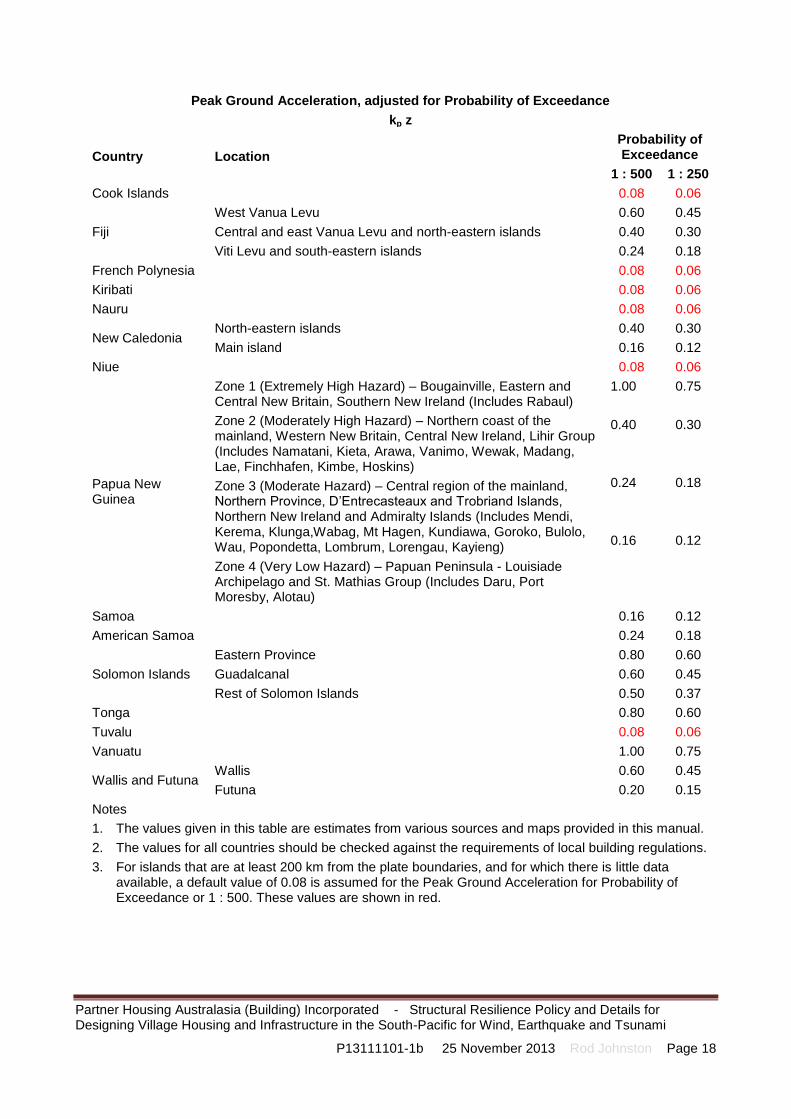
P13111101-1b 25 November 2013 Rod Johnston Page 18
Peak Ground Acceleration, adjusted for Probability of Exceedance
kp z
Country Location
Probability of Exceedance
1 : 500 1 : 250
Cook Islands 0.08 0.06
Fiji
West Vanua Levu
Central and east Vanua Levu and north-eastern islands
Viti Levu and south-eastern islands
0.60
0.40
0.24
0.45
0.30
0.18
French Polynesia 0.08 0.06
Kiribati 0.08 0.06
Nauru 0.08 0.06
New Caledonia North-eastern islands
Main island
0.40
0.16
0.30
0.12
Niue 0.08 0.06
Papua New Guinea
Zone 1 (Extremely High Hazard) – Bougainville, Eastern and Central New Britain, Southern New Ireland (Includes Rabaul)
Zone 2 (Moderately High Hazard) – Northern coast of the mainland, Western New Britain, Central New Ireland, Lihir Group (Includes Namatani, Kieta, Arawa, Vanimo, Wewak, Madang, Lae, Finchhafen, Kimbe, Hoskins)
Zone 3 (Moderate Hazard) – Central region of the mainland, Northern Province, D’Entrecasteaux and Trobriand Islands, Northern New Ireland and Admiralty Islands (Includes Mendi, Kerema, Klunga,Wabag, Mt Hagen, Kundiawa, Goroko, Bulolo, Wau, Popondetta, Lombrum, Lorengau, Kayieng)
Zone 4 (Very Low Hazard) – Papuan Peninsula - Louisiade Archipelago and St. Mathias Group (Includes Daru, Port Moresby, Alotau)
1.00
0.40
0.24
0.16
0.75
0.30
0.18
0.12
Samoa 0.16 0.12
American Samoa 0.24 0.18
Solomon Islands
Eastern Province
Guadalcanal
Rest of Solomon Islands
0.80
0.60
0.50
0.60
0.45
0.37
Tonga 0.80 0.60
Tuvalu 0.08 0.06
Vanuatu 1.00 0.75
Wallis and Futuna Wallis
Futuna
0.60
0.20
0.45
0.15
Notes
1. The values given in this table are estimates from various sources and maps provided in this manual.
2. The values for all countries should be checked against the requirements of local building regulations.
3. For islands that are at least 200 km from the plate boundaries, and for which there is little data available, a default value of 0.08 is assumed for the Peak Ground Acceleration for Probability of Exceedance or 1 : 500. These values are shown in red.

Partner Housing Australasia (Building) Incorporated - Structural Resilience Policy and Details for Designing Village Housing and Infrastructure in the South-Pacific for Wind, Earthquake and Tsunami
P13111101-1b 25 November 2013 Rod Johnston Page 19
This policy provides ultimate limit state loads, based on the following assumptions:
Analysis shall be consistent with AS 1170.4, except as follows.
Hazard factors shall be determined from the relevant Building Regulations or, if appropriate estimated from published data, some of which is shown below.
The values shown in the maps below correspond to the Peak Ground Acceleration with a Probability of Exceedance of 10% in 50 years (i.e. 1 : 500).
Reference: Y. Rong, Y, Park, J, Duggan, D, Mahdyiar, M and Bazzurro, P., Probabilistic Seismic Hazard Assessment for Pacific Island Countries 15 WCEE Lisboa, 2012

Partner Housing Australasia (Building) Incorporated - Structural Resilience Policy and Details for Designing Village Housing and Infrastructure in the South-Pacific for Wind, Earthquake and Tsunami
P13111101-1b 25 November 2013 Rod Johnston Page 20
Peak Ground Acceleration with a Probability of Exceedance of 10% in 50 years (i.e. 1 : 500)
References:
McCue, K., “Seismic hazard mapping in Australia, the South-west Pacific and South-east Asia” Global Seismic Hazard Assessment Program, Geoscience Australia http://www.seismo.ethz.ch/static/GSHAP/swpacific/swpac.gif

Partner Housing Australasia (Building) Incorporated - Structural Resilience Policy and Details for Designing Village Housing and Infrastructure in the South-Pacific for Wind, Earthquake and Tsunami
P13111101-1b 25 November 2013 Rod Johnston Page 21
Papua New Guinea
Generalised Seismic Hazard Zones of PNG - (Modified from the PNG National Standards Council, 1983)
Zone 1 (Extremely High Hazard) – Bougainville, Eastern and Central New Britain, Southern New Ireland
Zone 2 (Moderately High Hazard) – Northern coast of the mainland, Western New Britain, Central New Ireland, Lihir Group
Zone 3 (Moderate Hazard) – Central region of the mainland, Northern Province, D’Entrecasteaux and Trobriand Islands, Northern New Ireland and Admiralty Islands
Zone 4 (Very Low Hazard) – Papuan Peninsula - Louisiade Archipelago and St. Mathias GroupHazard map of PNG
References: Geosciences Australia; Anton, L., “Earthquake and Tsunami Hazard Mitigation in Papua New Guinea”; Geological Survey of Papua New Guinea; Papua New Guinea Building Regulation 1994

Partner Housing Australasia (Building) Incorporated - Structural Resilience Policy and Details for Designing Village Housing and Infrastructure in the South-Pacific for Wind, Earthquake and Tsunami
P13111101-1b 25 November 2013 Rod Johnston Page 22
Solomon Islands
Reference: http://neic.usgs.gov/neis/eq_depot/2007/eq_070816_gccj/neic_gccj_w.html

Partner Housing Australasia (Building) Incorporated - Structural Resilience Policy and Details for Designing Village Housing and Infrastructure in the South-Pacific for Wind, Earthquake and Tsunami
P13111101-1b 25 November 2013 Rod Johnston Page 23
Various Pacific Islands
Y. Rong, Y, Park, J, Duggan, D, Mahdyiar, M and Bazzurro, P., Probabilistic Seismic Hazard Assessment for Pacific Island Countries 15 WCEE Lisboa, 2012
http://earthquake.usgs.gov/earthquakes/world/png/gshap.php

Partner Housing Australasia (Building) Incorporated - Structural Resilience Policy and Details for Designing Village Housing and Infrastructure in the South-Pacific for Wind, Earthquake and Tsunami
P13111101-1b 25 November 2013 Rod Johnston Page 24
Reference: Petersen, M.D., Harmsen, S.C., Rukstales, K.S., Mueller, C.S., McNamara, D.E., Luco, Nicolas, and Walling, Melanie, 2012, Seismic hazard of American Samoa and Neighboring South Pacific Islands—Methods, data, parameters, and results: U.S. Geological Survey Open-File Report 2012–1087, 98 p.

Partner Housing Australasia (Building) Incorporated - Structural Resilience Policy and Details for Designing Village Housing and Infrastructure in the South-Pacific for Wind, Earthquake and Tsunami
P13111101-1b 25 November 2013 Rod Johnston Page 25
Notes on Tsunami Loads
Sites shall be analysed to determine whether they are prone to tsunamis, giving consideration to the following:
Distance from high water mark, Tdhw (km)
Height of finished floor above mean sea level, Tffl (m)
Distance from high earthquake area (Z > 0.4), Tequ (km)
Site specific exposure, Texp (2 is maximum risk; 1 is normal risk, 0 is no risk)
Tsunami risk factor (10 is maximum risk; 0 is no risk)
Rt =IF(Tdhw>2,0,IF(Tffl>20,0,IF(Tequ>1000,0, Texp *5/(MAX(Tdhw,0.2)*MAX(Tffl,1)*MAX(Tequ /100,5)))))
Design strategy
IF(Rt <1,"No design required",IF(Rt <5,"Design structure","Move structure"))
For structures that are required to be designed for tsunami (except those that should be moved), analysis shall be in accordance with the method in Australian Building Codes Board Handbook, Construction of Buildings in Flood Hazard Areas for velocity equal to the maximum of the calculated risk factor (m/s) or 1.5 m/s.
Structural components shall be designed to withstand the design event, assuming that the cladding is destroyed. Remaining cladding and other water-borne material, of a combined area equal to 20% of the building elevation area facing the tsunami shall be assumed for determination of the tsunami forces. It is also assumed that the water flows at depth numerically equal to the risk factor (m).
The following map for South-east Asia tsunamis is included to give a typical indication for the wave heights for a Probability of Exceedance of 1 in 500. While this information is not transferrable to the South Pacific, it does give a feel for the possible magnitude of tsunamis.

Partner Housing Australasia (Building) Incorporated - Structural Resilience Policy and Details for Designing Village Housing and Infrastructure in the South-Pacific for Wind, Earthquake and Tsunami
P13111101-1b 25 November 2013 Rod Johnston Page 26
Notes on Flood Loads
Sites shall be analysed to determine whether they are prone to flooding, giving consideration to the following:
Distance to closest water course, Fdwc (m)
Height of finished floor above normal level of water course, Fffl (m)
Catchment area, Fcat (km2)
Concentration of catchment runoff past structure, Fcon (2 is maximum; 1 is normal, 0 is no risk)
Flooding risk factor (10 is maximum risk; 0 is no risk)
Rf =IF(Fdwc >200,0,IF(Fffl >10,0,IF(Fcat <1,0, Fcon *MIN(Fdwc,100)/(MAX(Fdwc,10)*MAX(Fffl,2)))))
Design strategy
IF(Rf <1,"No design required",IF(Rf <5,"Design structure","Move structure"))
For structures that are required to be designed for flood (except those that should be moved), analysis shall be in accordance with the method in Australian Building Codes Board Handbook, Construction of Buildings in Flood Hazard Areas for a velocity equal to the maximum of the calculated risk factor (m/s) or 1.5 m/s.
Structural components shall be designed to withstand the design event, assuming that 100% of the cladding remains intact and the water flows at depth calculated from the topography.
Partner Housing Australasia (Building) Incorporated - Structural Resilience Policy and Details for Designing Village Housing and Infrastructure in the South-Pacific for Wind, Earthquake and Tsunami
P13111101-1b 25 November 2013 Rod Johnston Page 27
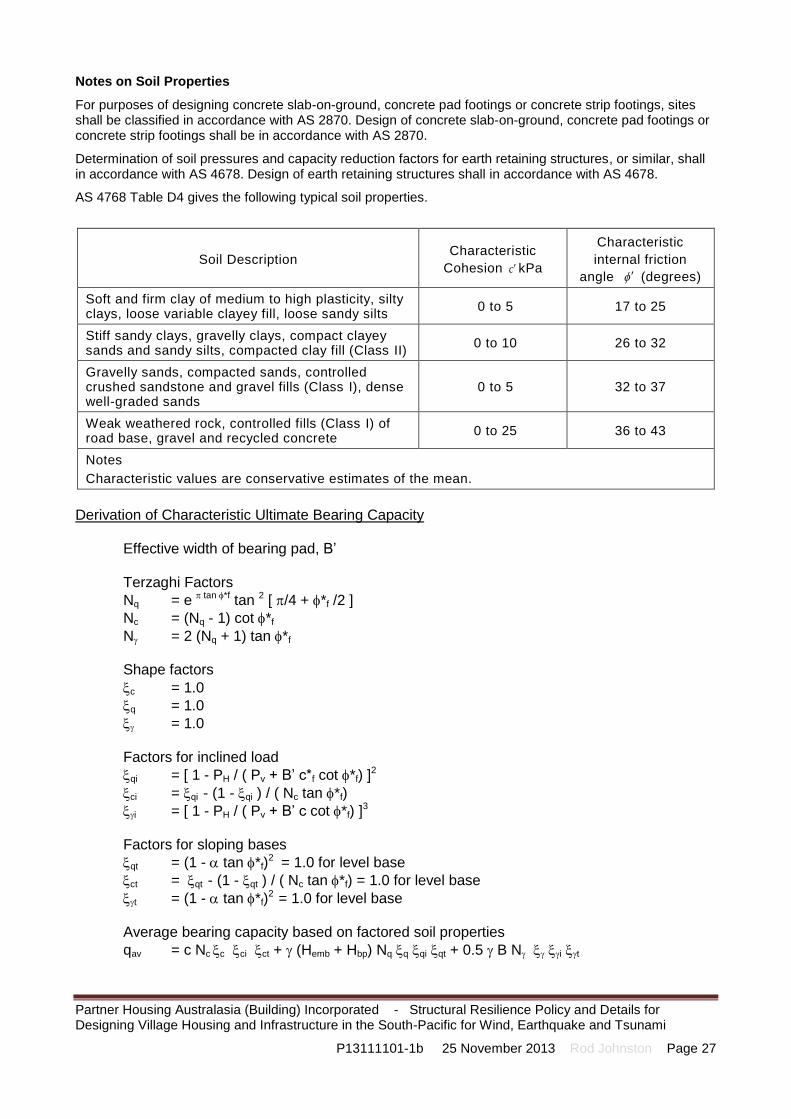
Notes on Soil Properties
For purposes of designing concrete slab-on-ground, concrete pad footings or concrete strip footings, sites shall be classified in accordance with AS 2870. Design of concrete slab-on-ground, concrete pad footings or concrete strip footings shall be in accordance with AS 2870.
Determination of soil pressures and capacity reduction factors for earth retaining structures, or similar, shall in accordance with AS 4678. Design of earth retaining structures shall in accordance with AS 4678.
AS 4768 Table D4 gives the following typical soil properties.
Soil Description Characteristic
Cohesion ckPa
Characteristic
internal friction
angle (degrees)
Soft and firm clay of medium to high plasticity, silty clays, loose variable clayey fill, loose sandy silts
0 to 5 17 to 25
Stiff sandy clays, gravelly clays, compact clayey sands and sandy silts, compacted clay fill (Class II)
0 to 10 26 to 32
Gravelly sands, compacted sands, controlled crushed sandstone and gravel fills (Class I), dense well-graded sands
0 to 5 32 to 37
Weak weathered rock, controlled fills (Class I) of road base, gravel and recycled concrete
0 to 25 36 to 43
Notes
Characteristic values are conservative estimates of the mean.
Derivation of Characteristic Ultimate Bearing Capacity
Effective width of bearing pad, B’ Terzaghi Factors
Nq = e tan *f tan 2 [ /4 + *f /2 ]
Nc = (Nq - 1) cot *f
N = 2 (Nq + 1) tan *f Shape factors
c = 1.0
q = 1.0
= 1.0 Factors for inclined load
qi = [ 1 - PH / ( Pv + B’ c*f cot *f) ]2
ci = qi - (1 - qi ) / ( Nc tan *f)
i = [ 1 - PH / ( Pv + B’ c cot *f) ]3
Factors for sloping bases
qt = (1 - tan *f)2 = 1.0 for level base
ct = qt - (1 - qt ) / ( Nc tan *f) = 1.0 for level base
t = (1 - tan *f)2 = 1.0 for level base
Average bearing capacity based on factored soil properties
qav = c Nc c ci ct + (Hemb + Hbp) Nq q qi qt + 0.5 B N i t

Partner Housing Australasia (Building) Incorporated - Structural Resilience Policy and Details for Designing Village Housing and Infrastructure in the South-Pacific for Wind, Earthquake and Tsunami
P13111101-1b 25 November 2013 Rod Johnston Page 28
Bearing capacity of the foundation Pv cap = qav B’
Based on this information, the following properties are assumed for various soils classified in accordance with AS2870.
Australia, New Zealand and Papua New Guinea
It is assumed that, due to the geological diversity of these countries, all of the following soil typess are possible.
Soil Type AS 2870 Site
Classification
Characteristic internal friction angle, degrees
Characteristic cohesion, kPa
Characteristic ultimate bearing capacity, kPa
Sand or rock A 36o 0 kPa 350 kPa
Slightly reactive clay S 30o 3 kPa 230 kPa
Moderately reactive clay M 27o 6 kPa 210 kPa
Highly reactive clay H1 24o 9 kPa 200 kPa
Highly reactive clay H2 24o 9 kPa 200 kPa
Extremely reactive clay E 20o 9 kPa 150 kPa
1. Characteristic internal friction angles and characteristic cohesions are conservative estimates of the mean values for the particular soil type, without capacity reduction factors
2. Characteristic bearing capacities are determined using values for internal friction angle that have been factored in accordance with AS 4678 for in-situ soil.
3. Characteristic bearing capacities have been calculated by the Terzaghi method, for vertical concentric load on 300 mm wide strip footings buried not less than 600 mm deep on undisturbed in-situ soil.
Volcanic Islands
Sites on volcanic islands, will be assumed to have the following properties
Soil Type AS 2870 Site
Classification
Characteristic internal friction angle, degrees
Characteristic cohesion, kPa
Characteristic ultimate bearing capacity, kPa
Close to beach - sand or rock
A 36o 0 kPa 350 kPa
Away from beach - moderately reactive clay
M 27o 6 kPa 210 kPa
Coral Atolls
Sites on islands consisting principally of coral atolls, will be assumed to have the following properties
Soil Type AS 2870 Site
Classification
Characteristic internal friction angle, degrees
Characteristic cohesion, kPa
Characteristic ultimate bearing capacity, kPa
Sand or rock A 36o 0 kPa 350 kPa

Partner Housing Australasia (Building) Incorporated - Structural Resilience Policy and Details for Designing Village Housing and Infrastructure in the South-Pacific for Wind, Earthquake and Tsunami
P13111101-1b 25 November 2013 Rod Johnston Page 29
Part 2 - References
Scope
This part provides references to various regulations and papers that have been used in the preparation of this document, and which provide additional information relevant to the design and construction of houses and village infrastructure.
Building Acts and Building Regulations – South Pacific
URL: http://www.paclii.org/pg/legis/consol_act/br1994182
Australia
National Construction Code 2014 – BCA Volume Two
Cook Islands
National Building Code for Cook Islands
Partial Commentary of the National Building Code Cook Islands
Home Building Manual Cook Islands
Cook Islands 1991 Building Controls and Standards
Cook Islands Building Controls and Standards (National Building Code) (Amendment) (No.2) Order 2005
Building Controls and Standard (National Building Code) (Amendment) (No.2) Order 2005 [32%] (From Cook Islands Sessional Legislation; 1 January 2005; 8 KB)
Building Controls and Standards Act 1991 [17%] (From Cook Islands Sessional Legislation; 1 KB)
Fiji
National Building Code for Fiji
Partial Commentary of the National Building Code Fiji
French Polynesia
Kiribati
Building Act 2006 [63%] (From Kiribati Sessional Legislation; 1 January 2006; 80 KB)
Nauru
New Caledonia
New Zealand
Building Regulations

Partner Housing Australasia (Building) Incorporated - Structural Resilience Policy and Details for Designing Village Housing and Infrastructure in the South-Pacific for Wind, Earthquake and Tsunami
P13111101-1b 25 November 2013 Rod Johnston Page 30
Niue
National Building Code for Niue
Partial Commentary of the National Building Code Niue
Home Building Manual Niue
Building Code Act 1992 [46%] (From Niue Consolidated Legislation; 1 January 1992; 28 KB)
Papua New Guinea
Building Regulation 1994 [100%] (From Papua New Guinea Consolidated Legislation; 1 January 1994; 656 KB)
Building Act 1971 [51%] (From Papua New Guinea Consolidated Legislation; 1 January 1971; 106 KB)
Public Health Ordinance 1932-1938 - Building Regulations [33%] (From Laws of the Territory of New Guinea 1921-1945 (Annotated); 37 KB)
Building Ordinance, 1929 [33%] (From Laws of the Territory of Papua 1888-1945 (Annotated); 8 KB)
Samoa
Ministry of Works Act 2002 [18%] (From Consolidated Acts of Samoa 2011; 1 January 2002; 62 KB)
American Samoa
Solomon Islands
National Building Code for Solomon Islands
Partial Commentary of the National Building Code Solomon Islands
Building Standards Ordinance 1991 [67%] (From Solomon Islands Western Province Consolidated Legislation 1999; 1 January 1991; 84 KB)
Local Government Act - Subsidiary [33%] (From Solomon Islands Consolidated Legislation; 440 KB)
Tonga
Building Control and Standards Act 2002 [33%] (From Tonga Sessional Legislation; 1 January 2002; 26 KB)
Building Code Regulations 2007 [31%] (From Tonga Subsidiary Legislation; 1 January 2007; 4 KB)
Tuvalu
National Building Code for Tuvalu
Partial Commentary of the National Building Code Tuvalu
Home Building Manual Tuvalu

Partner Housing Australasia (Building) Incorporated - Structural Resilience Policy and Details for Designing Village Housing and Infrastructure in the South-Pacific for Wind, Earthquake and Tsunami
P13111101-1b 25 November 2013 Rod Johnston Page 31
Vanuatu
National Building Code for Vanuatu
Partial Commentary of the National Building Code Vanuatu
Wallis and Futuna
Load Combinations, Permanent Loads, Imposed Loads
Unless specifically stated otherwise in the relevant Building Regulations, the latest published version (including any published amendments) of the Standards specified in this policy shall be used.
Australian & New Zealand Standard AS/NZS 1170.0:2002 (Including Amendments 1, 2, 3, 4, and 5)
Australian & New Zealand Standard AS/NZS 1170.1:2002 (Including Amendments 1 and 2)
Wind
Australian & New Zealand Standard AS/NZS 1170.2:2011 (Including Amendments 1 and 2)
Australian Standard AS 4055:2012
Standards Australia Handbook HB212:2002
Earthquakes
Australian Standard AS 1170.4:2007
New Zealand Standard NZS 1170.5:2004
Anon, Science Plan on Hazards and Disasters – Earthquakes Floods and Landslides, ICSU Regional Office for Asia and the Pacific, 2008
Anon, Suva Earthquake Risk Management Scenario Pilot Project (Sermp) Part I Summary Report January 2002 South Pacific Disaster Reduction Program (Spdrp) Report
Anon, Earthquake Intensity Risk Zones & Presence of UN/ISDR in Asia Pacific, UN/ISDR 10 April 2008
Anton, L., Earthquake and Tsunami Hazard Mitigation in Papua New Guinea, Geological Survey Of Papua New Guinea, P.O. Box 323, Port Moresby, National Capital District, Papua New Guinea (p: +(675) 321 4500, f: +(675) 321 3976, e: [email protected])
McCue, K., Seismic hazard mapping in Australia, the South-west Pacific and South-east Asia, ANNALI DI GEOFISICA, Vol 42, No 6, December 1999
Petersen, M.D., Harmsen, S.C., Rukstales, K.S., Mueller, C.S., McNamara, D.E., Luco, Nicolas, and Walling, M., Seismic hazard of American Samoa and neighboring South Pacific Islands—Methods, data, parameters, and results: 2012, U.S. Geological Survey Open-File Report 2012–1087, 98 p.
Rong, Y., Park, J., Duggan, D., Mahdyiar, M. & Bazzurro, P. Probabilistic Seismic Hazard Assessment for Pacific Island Countries, 15 WCEE, Lisboa 2012
Wilson, J & Lam, N., A recommended earthquake response spectrum model for Australia, Australian Journal of Structural Engineering, Vol 5, No 1, Institution of Engineers, Australia, 2003
Wijanto, S., World Housing Encyclopedia Report Country: Indonesia Housing Type: Unreinforced clay brick masonry house, 6/5/2002( Modified 7/2/2003)

Partner Housing Australasia (Building) Incorporated - Structural Resilience Policy and Details for Designing Village Housing and Infrastructure in the South-Pacific for Wind, Earthquake and Tsunami
P13111101-1b 25 November 2013 Rod Johnston Page 32
Tsunamis and Floods
Australian Building Codes Board Handbook, Construction of Buildings in Flood Hazard Areas, Version 2012.2.
Soil Load and Movement
Australian Standard AS 2870:2011
Australian Standard AS 4678:2002 (Including Amendment 1 and 2)
General References
Johnston, R.K. (July 2001), Australian Involvement in Constructing Affordable Housing in Developing Countries, Deakin University, AID719
Schilderman, T. & Lowe, L., Regulatory Issues Affecting Shelter Development by The Urban Poor, ITDG

Partner Housing Australasia (Building) Incorporated - Structural Resilience Policy and Details for Designing Village Housing and Infrastructure in the South-Pacific for Wind, Earthquake and Tsunami
P13111101-1b 25 November 2013 Rod Johnston Page 33
Part 3 – Country Design and Analysis Assumptions
Scope
This part provides the design and analysis assumptions for each of the countries covered by this manual, taking account of the location, proximity to cyclonic wind zones, proximity to high earthquake areas and plate boundaries, typical topography and susceptibility to tsunamis.
Details Refer to each of the following pages for the default assumptions #
Partner Housing Australasia (Building) Incorporated - Structural Resilience Policy and Details for Designing Village Housing and Infrastructure in the South-Pacific for Wind, Earthquake and Tsunami
P13111101-1b 25 November 2013 Rod Johnston Page 34
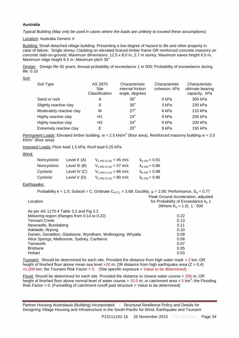
Australia
Typical Building (May only be used in cases where the loads are unlikely to exceed these assumptions)
Location: Australia Generic #
Building: Small detached village building; Presenting a low degree of hazard to life and other property in case of failure; Single storey; Cladding on elevated braced timber frame OR reinforced concrete masonry on concrete slab-on-ground; Maximum dimensions: 12.5 x 8.0 m, 2.7 m storey, Maximum eaves height 6.0 m, Maximum ridge height 8.5 m, Maximum pitch 35
o
Design: Design life 50 years; Annual probability of exceedance 1 in 500; Probability of exceedance during life: 0.10
Soil:
Soil Type AS 2870 Site
Classification
Characteristic internal friction angle, degrees
Characteristic cohesion, kPa
Characteristic ultimate bearing capacity, kPa
Sand or rock A 36o 0 kPa 350 kPa
Slightly reactive clay S 30o 3 kPa 230 kPa
Moderately reactive clay M 27o 6 kPa 210 kPa
Highly reactive clay H1 24o 9 kPa 200 kPa
Highly reactive clay H2 24o 9 kPa 200 kPa
Extremely reactive clay E 20o 9 kPa 150 kPa
Permanent Loads: Elevated timber building, w = 2.5 kN/m2 (floor area), Reinforced masonry building w = 3.5
kN/m2 (floor area)
Imposed Loads: Floor load 1.5 kPa; Roof load 0.25 kPa
Wind:
Noncyclonic Level II (A) Vu 500 (3,10) = 45 m/s kp 250 = 0.91
Noncyclonic Level III (B) Vu 500 (3,10) = 57 m/s kp 250 = 0.86
Cyclonic Level IV (C) Vu 500( 3,10) = 66 m/s kp 250 = 0.88
Cyclonic Level V (D) Vu 500 (3,10) = 80 m/s kp 250 = 0.86
Earthquake:
Probability k = 1.0; Subsoil = C; Ordinate Ch(T1) = 3.68; Ductility, μ = 2.00; Performance, Sp = 0.77
Location Peak Ground Acceleration, adjusted for Probability of Exceedance kp z
(Where Kp = 1.0) 1 : 500
As per AS 1170.4 Table 3.2 and Fig 3.2 Mekering region (Ranges from 0.14 to 0.22) Tennant Creek Newcastle, Bundaberg Adelaide, Wyong Darwin, Geraldton, Gladstone, Wyndham, Wollongong, Whyalla Alice Springs, Melbourne, Sydney, Canberra Tamworth Brisbane Hobart
0.22 0.13 0.11 0.10 0.09 0.08 0.07 0.05 0.03
Tsunami: Should be determined for each site. Provided the distance from high water mark > 2 km; OR height of finished floor above mean sea level >20 m; OR distance from high earthquake area (Z > 0.4) >1,000 km; the Tsunami Risk Factor = 0 (Site specific exposure = Value to be determined)
Flood: Should be determined for each site. Provided the distance to closest water course > 200 m; OR height of finished floor above normal level of water course > 10.0 m; or catchment area < 5 km
2; the Flooding
Risk Factor = 0. (Funnelling of catchment runoff past structure = Value to be determined)

Partner Housing Australasia (Building) Incorporated - Structural Resilience Policy and Details for Designing Village Housing and Infrastructure in the South-Pacific for Wind, Earthquake and Tsunami
P13111101-1b 25 November 2013 Rod Johnston Page 35
Cook Islands
Typical Building (May only be used in cases where the loads are unlikely to exceed these assumptions)
Location: Cook Islands Generic #
Building: Small detached village building; Presenting a low degree of hazard to life and other property in case of failure; Single storey; Cladding on elevated braced timber frame OR Reinforced concrete masonry on concrete slab-on-ground; Maximum dimensions: 12.5 x 8.0 m, 2.7 m storey, Maximum eaves height 6.0 m, Maximum ridge height 8.5 m, Maximum pitch 35
o
Design: Design life 25 years; Annual probability of exceedance 1 in 250; Probability of exceedance during life: 0.10
Soil:
Soil Type AS 2870 Site
Classification
Characteristic internal friction angle, degrees
Characteristic cohesion, kPa
Characteristic ultimate bearing capacity, kPa
Close to beach - sand or rock
A 36o 0 kPa 350 kPa
Away from beach - moderately reactive clay
M 27o 6 kPa 210 kPa
Permanent Loads: Elevated timber building, w = 2.5 kN/m2 (floor area), Reinforced masonry building w = 3.5
kN/m2 (floor area)
Imposed Loads: Floor load 1.5 kPa; Roof load 0.25 kPa
Wind: Cyclonic Cyclonic Level IV (C) Vu 500( 3,10) = 66 m/s kp 250 = 0.88
The National Building Code for Cook Islands 1990 calls up the version AS 1170.2 that was in place at the time. It also provides further information for the permissible stress method. However this policy provides ultimate limit state loads, which may be derived using the following passages from the National Building Code for Cook Islands 1990. “When using Part 2 of the standard the following provisions apply: a limit state basic wind speed of 60 m/s to all areas…… The bulk of the developing areas in the Cook Islands are such that simple buildings up to 6 m height, …… [and] category 2 terrain and an upwind slope of 1 : 10 for escarpments …”
Earthquake: Probability kp = 0.75; Hazard Z500 = 0.08; Subsoil = C; Ordinate Ch(T1) = 3.68; Ductility, μ = 2.00; Performance, Sp = 0.77
Tsunami: Should be determined for each site. Provided the distance from high water mark > 2 km; OR height of finished floor above mean sea level >20 m; OR distance from high earthquake area (Z > 0.4) >1,000 km; the Tsunami Risk Factor = 0 (Site specific exposure = Value to be determined)
Flood: Should be determined for each site. Provided the distance to closest water course > 200 m; OR height of finished floor above normal level of water course > 10.0 m; or catchment area < 5 km
2; the Flooding
Risk Factor = 0. (Funnelling of catchment runoff past structure = Value to be determined)

Partner Housing Australasia (Building) Incorporated - Structural Resilience Policy and Details for Designing Village Housing and Infrastructure in the South-Pacific for Wind, Earthquake and Tsunami
P13111101-1b 25 November 2013 Rod Johnston Page 36
Fiji
Typical Building (May only be used in cases where the loads are unlikely to exceed these assumptions)
Location: Fiji Generic #
Building: Small detached village building; Presenting a low degree of hazard to life and other property in case of failure;
Single storey; Cladding on elevated braced timber frame OR Reinforced concrete masonry on concrete slab-on-ground;
Maximum dimensions: 12.5 x 8.0 m, 2.7 m storey, Maximum eaves height 6.0 m, Maximum ridge height 8.5 m, Maximum pitch 35
o
Design: Design life 25 years; Annual probability of exceedance 1 in 250; Probability of exceedance during life: 0.10
Soil:
Soil Type AS 2870 Site
Classification
Characteristic internal friction angle, degrees
Characteristic cohesion, kPa
Characteristic ultimate bearing capacity, kPa
Close to beach - sand or rock
A 36o 0 kPa 350 kPa
Away from beach - moderately reactive clay
M 27o 6 kPa 210 kPa
Permanent Loads: Elevated timber building, w = 2.5 kN/m2 (floor area), Reinforced masonry building w = 3.5
kN/m2 (floor area)
Imposed Loads: Floor load 1.5 kPa; Roof load 0.25 kPa
Wind: Cyclonic Level IV (C) Vu 500( 3,10) = 66 m/s kp 250 = 0.88
The National Building Code for Fiji 1990 calls up the version AS 1170.2 that was in place at the time. It also provides further information for the permissible stress method. However this policy provides ultimate limit state loads, which may be derived using the following passages from the National Building Code for Fiji 1990. “When using Part 2 of the standard the following provisions apply: a limit state basic wind speed of 70 m/s to all areas”
Earthquake: Probability kp = 0.75; Hazard Z500 = 0.60 (West Vanua Levu), 0.40 (Central and east Vanua Levu and north-eastern islands), 0.24 (Viti Levu and south-eastern islands); Subsoil = C; Ordinate Ch(T1) = 3.68; Ductility, μ = 2.00; Performance, Sp = 0.77
Tsunami: Should be determined for each site. Distance from high water mark = …… km; Height of finished floor above mean sea level =…..m; Distance from high earthquake area (Z > 0.4) >….. km; Site specific exposure = ………. Tsunami Risk Factor = ……
Flood: Should be determined for each site. Provided the distance to closest water course > 200 m; OR height of finished floor above normal level of water course > 10.0 m; or catchment area < 5 km
2; the Flooding
Risk Factor = 0. (Funnelling of catchment runoff past structure = Value to be determined)

Partner Housing Australasia (Building) Incorporated - Structural Resilience Policy and Details for Designing Village Housing and Infrastructure in the South-Pacific for Wind, Earthquake and Tsunami
P13111101-1b 25 November 2013 Rod Johnston Page 37
French Polynesia
Typical Building (May only be used in cases where the loads are unlikely to exceed these assumptions)
Location: French Polynesia Generic #
Building: Small detached village building; Presenting a low degree of hazard to life and other property in case of failure;
Single storey; Cladding on elevated braced timber frame OR Reinforced concrete masonry on concrete slab-on-ground;
Maximum dimensions: 12.5 x 8.0 m, 2.7 m storey, Maximum eaves height 6.0 m, Maximum ridge height 8.5 m, Maximum pitch 35
o
Design: Design life 25 years; Annual probability of exceedance 1 in 250; Probability of exceedance during life: 0.10
Soil:
Soil Type AS 2870 Site
Classification
Characteristic internal friction angle, degrees
Characteristic cohesion, kPa
Characteristic ultimate bearing capacity, kPa
Close to beach - sand or rock
A 36o 0 kPa 350 kPa
Away from beach - moderately reactive clay
M 27o 6 kPa 210 kPa
Permanent Loads: Elevated timber building, w = 2.5 kN/m2 (floor area), Reinforced masonry building w = 3.5
kN/m2 (floor area)
Imposed Loads: Floor load 1.5 kPa; Roof load 0.25 kPa
Wind: Cyclonic Level IV (C) Vu 500( 3,10) = 66 m/s kp 250 = 0.88
Earthquake: Probability kp = 0.75; Hazard Z500 = 0.08; Subsoil = C; Ordinate Ch(T1) = 3.68; Ductility, μ = 2.00; Performance, Sp = 0.77
Tsunami: Should be determined for each site. Provided the distance from high water mark > 2 km; OR height of finished floor above mean sea level >20 m; OR distance from high earthquake area (Z > 0.4) >1,000 km; the Tsunami Risk Factor = 0 (Site specific exposure = Value to be determined)
Flood: Should be determined for each site. Provided the distance to closest water course > 200 m; OR height of finished floor above normal level of water course > 10.0 m; or catchment area < 5 km
2; the Flooding
Risk Factor = 0. (Funnelling of catchment runoff past structure = Value to be determined)

Partner Housing Australasia (Building) Incorporated - Structural Resilience Policy and Details for Designing Village Housing and Infrastructure in the South-Pacific for Wind, Earthquake and Tsunami
P13111101-1b 25 November 2013 Rod Johnston Page 38
Kiribati
Typical Building (May only be used in cases where the loads are unlikely to exceed these assumptions)
Location: Kiribati Generic #
Building: Small detached village building; Presenting a low degree of hazard to life and other property in case of failure;
Single storey; Cladding on elevated braced timber frame OR Reinforced concrete masonry on concrete slab-on-ground;
Maximum dimensions: 12.5 x 8.0 m, 2.7 m storey, Maximum eaves height 6.0 m, Maximum ridge height 8.5 m, Maximum pitch 35
o
Design: Design life 25 years; Annual probability of exceedance 1 in 250; Probability of exceedance during life: 0.10
Soil:
Soil Type AS 2870 Site
Classification
Characteristic internal friction angle, degrees
Characteristic cohesion, kPa
Characteristic ultimate bearing capacity, kPa
Sand or rock A 36o 0 kPa 350 kPa
Permanent Loads: Elevated timber building, w = 2.5 kN/m2 (floor area), Reinforced masonry building w = 3.5
kN/m2 (floor area)
Imposed Loads: Floor load 1.5 kPa; Roof load 0.25 kPa
Wind: Noncyclonic Level I Vu 500 (3,10) = 40 m/s kp 250 = 0.90
Earthquake: Probability kp = 0.75; Hazard Z500 = 0.08; Subsoil = C; Ordinate Ch(T1) = 3.68; Ductility, μ = 2.00; Performance, Sp = 0.77
Tsunami: Should be determined for each site. Provided the distance from high water mark > 2 km; OR height of finished floor above mean sea level >20 m; OR distance from high earthquake area (Z > 0.4) >1,000 km; the Tsunami Risk Factor = 0 (Site specific exposure = Value to be determined)
Flood: Should be determined for each site. Provided the distance to closest water course > 200 m; OR height of finished floor above normal level of water course > 10.0 m; or catchment area < 5 km
2; the Flooding
Risk Factor = 0. (Funnelling of catchment runoff past structure = Value to be determined)

Partner Housing Australasia (Building) Incorporated - Structural Resilience Policy and Details for Designing Village Housing and Infrastructure in the South-Pacific for Wind, Earthquake and Tsunami
P13111101-1b 25 November 2013 Rod Johnston Page 39
Nauru
Typical Building (May only be used in cases where the loads are unlikely to exceed these assumptions)
Location: Nauru Generic #
Building: Small detached village building; Presenting a low degree of hazard to life and other property in case of failure;
Single storey; Cladding on elevated braced timber frame OR Reinforced concrete masonry on concrete slab-on-ground;
Maximum dimensions: 12.5 x 8.0 m, 2.7 m storey, Maximum eaves height 6.0 m, Maximum ridge height 8.5 m, Maximum pitch 35
o
Design: Design life 25 years; Annual probability of exceedance 1 in 250; Probability of exceedance during life: 0.10
Soil:
Soil Type AS 2870 Site
Classification
Characteristic internal friction angle, degrees
Characteristic cohesion, kPa
Characteristic ultimate bearing capacity, kPa
Sand or rock A 36o 0 kPa 350 kPa
Permanent Loads: Elevated timber building, w = 2.5 kN/m2 (floor area), Reinforced masonry building w = 3.5
kN/m2 (floor area)
Imposed Loads: Floor load 1.5 kPa; Roof load 0.25 kPa
Wind: Noncyclonic Level I Vu 500 (3,10) = 40 m/s kp 250 = 0.90
Earthquake: Probability kp = 0.75; Hazard Z500 = 0.08; Subsoil = C; Ordinate Ch(T1) = 3.68; Ductility, μ = 2.00; Performance, Sp = 0.77
Tsunami: Should be determined for each site. Provided the distance from high water mark > 2 km; OR height of finished floor above mean sea level >20 m; OR distance from high earthquake area (Z > 0.4) >1,000 km; the Tsunami Risk Factor = 0 (Site specific exposure = Value to be determined)
Flood: Should be determined for each site. Provided the distance to closest water course > 200 m; OR height of finished floor above normal level of water course > 10.0 m; or catchment area < 5 km
2; the Flooding
Risk Factor = 0. (Funnelling of catchment runoff past structure = Value to be determined)

Partner Housing Australasia (Building) Incorporated - Structural Resilience Policy and Details for Designing Village Housing and Infrastructure in the South-Pacific for Wind, Earthquake and Tsunami
P13111101-1b 25 November 2013 Rod Johnston Page 40
New Caledonia
Typical Building (May only be used in cases where the loads are unlikely to exceed these assumptions)
Location: New Caledonia Generic #
Building: Small detached village building; Presenting a low degree of hazard to life and other property in case of failure;
Single storey; Cladding on elevated braced timber frame OR Reinforced concrete masonry on concrete slab-on-ground;
Maximum dimensions: 12.5 x 8.0 m, 2.7 m storey, Maximum eaves height 6.0 m, Maximum ridge height 8.5 m, Maximum pitch 35
o
Design: Design life 25 years; Annual probability of exceedance 1 in 250; Probability of exceedance during life: 0.10
Soil:
Soil Type AS 2870 Site
Classification
Characteristic internal friction angle, degrees
Characteristic cohesion, kPa
Characteristic ultimate bearing capacity, kPa
Close to beach - sand or rock
A 36o 0 kPa 350 kPa
Away from beach - moderately reactive clay
M 27o 6 kPa 210 kPa
Permanent Loads: Elevated timber building, w = 2.5 kN/m2 (floor area), Reinforced masonry building w = 3.5
kN/m2 (floor area)
Imposed Loads: Floor load 1.5 kPa; Roof load 0.25 kPa
Wind: Cyclonic Level IV (C) Vu 500( 3,10) = 66 m/s kp 250 = 0.88
Earthquake: Probability kp = 0.75; Hazard Z500 = 0.40 (North-eastern islands), 0.16 (Main island); Subsoil = C; Ordinate Ch(T1) = 3.68; Ductility, μ = 2.00; Performance, Sp = 0.77
Tsunami: Should be determined for each site. Distance from high water mark = …… km; Height of finished floor above mean sea level =…..m; Distance from high earthquake area (Z > 0.4) >….. km; Site specific exposure = ………. Tsunami Risk Factor = ……
Flood: Should be determined for each site. Provided the distance to closest water course > 200 m; OR height of finished floor above normal level of water course > 10.0 m; or catchment area < 5 km
2; the Flooding
Risk Factor = 0. (Funnelling of catchment runoff past structure = Value to be determined)

Partner Housing Australasia (Building) Incorporated - Structural Resilience Policy and Details for Designing Village Housing and Infrastructure in the South-Pacific for Wind, Earthquake and Tsunami
P13111101-1b 25 November 2013 Rod Johnston Page 41
New Zealand
Typical Building (May only be used in cases where the loads are unlikely to exceed these assumptions)
Location: New Zealand Generic #
Building: Small detached village building; Presenting a low degree of hazard to life and other property in case of failure;
Single storey; Cladding on elevated braced timber frame OR Reinforced concrete masonry on concrete slab-on-ground;
Maximum dimensions: 12.5 x 8.0 m, 2.7 m storey, Maximum eaves height 6.0 m, Maximum ridge height 8.5 m, Maximum pitch 35
o
Design: Design life 25 years; Annual probability of exceedance 1 in 250; Probability of exceedance during life: 0.10
Soil:
Soil Type AS 2870 Site
Classification
Characteristic internal friction angle, degrees
Characteristic cohesion, kPa
Characteristic ultimate bearing capacity, kPa
Sand or rock A 36o 0 kPa 350 kPa
Slightly reactive clay S 30o 3 kPa 230 kPa
Moderately reactive clay M 27o 6 kPa 210 kPa
Highly reactive clay H1 24o 9 kPa 200 kPa
Highly reactive clay H2 24o 9 kPa 200 kPa
Extremely reactive clay E 20o 9 kPa 150 kPa
Permanent Loads: Elevated timber building, w = 2.5 kN/m2 (floor area), Reinforced masonry building w = 3.5
kN/m2 (floor area)
Imposed Loads: Floor load 1.5 kPa; Roof load 0.25 kPa
Wind: Noncyclonic Level II (A) Vu 500 (3,10) = 45 m/s kp 250 = 0.91 Noncyclonic Level III (W) Vu 500( 3,10) = 51 m/s kp 250 = 0.92
Earthquake:
Probability k = 0.75;; Subsoil = C; Ordinate Ch(T1) = 3.68; Ductility, μ = 2.00; Performance, Sp = 0.77
Location Peak Ground Acceleration, adjusted
for Probability of Exceedance kp z 1 : 500 (Where Kp = 1.0)
As per NZS 1170.5 Table 3.3 and Figs 3.3, 3.4, 3.5
Auckland, Dunedin, Palmerston
Hamilton, Akaroa
Christchurch
Wellington, Seddon, Hutt Valley, Ward, Cheviot, Otaki
Otira, Arthurs Pass (maximum value)
0.13
0.16
0.22
0.40
0.60
Tsunami: Should be determined for each site. Distance from high water mark = …… km; Height of finished floor above mean sea level =…..m; Distance from high earthquake area (Z > 0.4) >….. km; Site specific exposure = ………. Tsunami Risk Factor = ……
Flood: Should be determined for each site. Provided the distance to closest water course > 200 m; OR height of finished floor above normal level of water course > 10.0 m; or catchment area < 5 km
2; the Flooding
Risk Factor = 0. (Funnelling of catchment runoff past structure = Value to be determined)

Partner Housing Australasia (Building) Incorporated - Structural Resilience Policy and Details for Designing Village Housing and Infrastructure in the South-Pacific for Wind, Earthquake and Tsunami
P13111101-1b 25 November 2013 Rod Johnston Page 42
Niue
Typical Building (May only be used in cases where the loads are unlikely to exceed these assumptions)
Location: Niue Generic #
Building: Small detached village building; Presenting a low degree of hazard to life and other property in case of failure;
Single storey; Cladding on elevated braced timber frame OR Reinforced concrete masonry on concrete slab-on-ground;
Maximum dimensions: 12.5 x 8.0 m, 2.7 m storey, Maximum eaves height 6.0 m, Maximum ridge height 8.5 m, Maximum pitch 35
o
Design: Design life 25 years; Annual probability of exceedance 1 in 250; Probability of exceedance during life: 0.10
Soil:
Soil Type AS 2870 Site
Classification
Characteristic internal friction angle, degrees
Characteristic cohesion, kPa
Characteristic ultimate bearing capacity, kPa
Sand or rock A 36o 0 kPa 350 kPa
Permanent Loads: Elevated timber building, w = 2.5 kN/m2 (floor area), Reinforced masonry building w = 3.5
kN/m2 (floor area)
Imposed Loads: Floor load 1.5 kPa; Roof load 0.25 kPa
Wind: Cyclonic Level IV (C) Vu 500( 3,10) = 66 m/s kp 250 = 0.88
Earthquake: Probability kp = 0.75; Hazard Z500 = 0.08; Subsoil = C; Ordinate Ch(T1) = 3.68; Ductility, μ = 2.00; Performance, Sp = 0.77
Tsunami: Should be determined for each site. Distance from high water mark = …… km; Height of finished floor above mean sea level =…..m; Distance from high earthquake area (Z > 0.4) >….. km; Site specific exposure = ………. Tsunami Risk Factor = ……
Flood: Should be determined for each site. Provided the distance to closest water course > 200 m; OR height of finished floor above normal level of water course > 10.0 m; or catchment area < 5 km
2; the Flooding
Risk Factor = 0. (Funnelling of catchment runoff past structure = Value to be determined)

Partner Housing Australasia (Building) Incorporated - Structural Resilience Policy and Details for Designing Village Housing and Infrastructure in the South-Pacific for Wind, Earthquake and Tsunami
P13111101-1b 25 November 2013 Rod Johnston Page 43
Papua New Guinea
Typical Building (May only be used in cases where the loads are unlikely to exceed these assumptions)
Location: Papua New Guinea Generic #
Building: Small detached village building; Presenting a low degree of hazard to life and other property in case of failure;
Single storey; Cladding on elevated braced timber frame OR Reinforced concrete masonry on concrete slab-on-ground;
Maximum dimensions: 12.5 x 8.0 m, 2.7 m storey, Maximum eaves height 6.0 m, Maximum ridge height 8.5 m, Maximum pitch 35
o
Design: Design life 25 years; Annual probability of exceedance 1 in 250; Probability of exceedance during life: 0.10
Soil:
Soil Type AS 2870 Site
Classification
Characteristic internal friction angle, degrees
Characteristic cohesion, kPa
Characteristic ultimate bearing capacity, kPa
Sand or rock A 36o 0 kPa 350 kPa
Slightly reactive clay S 30o 3 kPa 230 kPa
Moderately reactive clay M 27o 6 kPa 210 kPa
Highly reactive clay H1 24o 9 kPa 200 kPa
Highly reactive clay H2 24o 9 kPa 200 kPa
Extremely reactive clay E 20o 9 kPa 150 kPa
Permanent Loads: Elevated timber building, w = 2.5 kN/m2 (floor area), Reinforced masonry building w = 3.5
kN/m2 (floor area)
Imposed Loads: Floor load 1.5 kPa; Roof load 0.25 kPa
Wind: Most of the country except south-east. (refer also to map for reduced velocities) Noncyclonic Level I Vu 500 (3,10) = 40 m/s kp 250 = 0.90
South-eastern peninsular (Including Milne Bay) Cyclonic Level IV (C) Vu 500( 3,10) = 66 m/s kp 250 = 0.88
Earthquake: Probability kp = 0.75; Hazard Z500 = As per table below; Subsoil = C; Ordinate Ch(T1) = 3.68; Ductility, μ = 2.00; Performance, Sp = 0.77
Location Hazard Z500
Zone 1 (Extremely High Hazard) – Bougainville, Eastern and Central New Britain, Southern New Ireland (Includes Rabaul)
Zone 2 (Moderately High Hazard) – Northern coast of the mainland, Western New Britain, Central New Ireland, Lihir Group (Includes Namatani, Kieta, Arawa, Vanimo, Wewak, Madang, Lae, Finchhafen, Kimbe, Hoskins)
Zone 3 (Moderate Hazard) – Central region of the mainland, Northern Province, D’Entrecasteaux and Trobriand Islands, Northern New Ireland and Admiralty Islands (Includes Mendi, Kerema, Klunga,Wabag, Mt Hagen, Kundiawa, Goroko, Bulolo, Wau, Popondetta, Lombrum, Lorengau, Kayieng)
Zone 4 (Very Low Hazard) – Papuan Peninsula - Louisiade Archipelago and St. Mathias Group (Includes Daru, Port Moresby, Alotau)
1.00
0.40
0.24
0.16
Tsunami: Should be determined for each site. Distance from high water mark = …… km; Height of finished floor above mean sea level =…..m; Distance from high earthquake area (Z > 0.4) >….. km; Site specific exposure = ………. Tsunami Risk Factor = ……
Flood: Should be determined for each site. Provided the distance to closest water course > 200 m; OR height of finished floor above normal level of water course > 10.0 m; or catchment area < 5 km
2; the Flooding
Risk Factor = 0. (Funnelling of catchment runoff past structure = Value to be determined)

Partner Housing Australasia (Building) Incorporated - Structural Resilience Policy and Details for Designing Village Housing and Infrastructure in the South-Pacific for Wind, Earthquake and Tsunami
P13111101-1b 25 November 2013 Rod Johnston Page 44
Samoa
Typical Building (May only be used in cases where the loads are unlikely to exceed these assumptions)
Location: Samoa Generic #
Building: Small detached village building; Presenting a low degree of hazard to life and other property in case of failure;
Single storey; Cladding on elevated braced timber frame OR Reinforced concrete masonry on concrete slab-on-ground;
Maximum dimensions: 12.5 x 8.0 m, 2.7 m storey, Maximum eaves height 6.0 m, Maximum ridge height 8.5 m, Maximum pitch 35
o
Design: Design life 25 years; Annual probability of exceedance 1 in 250; Probability of exceedance during life: 0.10
Soil:
Soil Type AS 2870 Site
Classification
Characteristic internal friction angle, degrees
Characteristic cohesion, kPa
Characteristic ultimate bearing capacity, kPa
Close to beach - sand or rock
A 36o 0 kPa 350 kPa
Away from beach - moderately reactive clay
M 27o 6 kPa 210 kPa
Permanent Loads: Elevated timber building, w = 2.5 kN/m2 (floor area), Reinforced masonry building w = 3.5
kN/m2 (floor area)
Imposed Loads: Floor load 1.5 kPa; Roof load 0.25 kPa
Wind: Cyclonic Level IV (C) Vu 500( 3,10) = 66 m/s kp 250 = 0.88
Earthquake: Probability kp = 0.75; Hazard Z500 = 0.16; Subsoil = C; Ordinate Ch(T1) = 3.68; Ductility, μ = 2.00; Performance, Sp = 0.77
Tsunami: Should be determined for each site. Distance from high water mark = …… km; Height of finished floor above mean sea level =…..m; Distance from high earthquake area (Z > 0.4) >….. km; Site specific exposure = ………. Tsunami Risk Factor = ……
Flood: Should be determined for each site. Provided the distance to closest water course > 200 m; OR height of finished floor above normal level of water course > 10.0 m; or catchment area < 5 km
2; the Flooding
Risk Factor = 0. (Funnelling of catchment runoff past structure = Value to be determined)

Partner Housing Australasia (Building) Incorporated - Structural Resilience Policy and Details for Designing Village Housing and Infrastructure in the South-Pacific for Wind, Earthquake and Tsunami
P13111101-1b 25 November 2013 Rod Johnston Page 45
American Samoa
Typical Building (May only be used in cases where the loads are unlikely to exceed these assumptions)
Location: American Samoa Generic #
Building: Small detached village building; Presenting a low degree of hazard to life and other property in case of failure;
Single storey; Cladding on elevated braced timber frame OR Reinforced concrete masonry on concrete slab-on-ground;
Maximum dimensions: 12.5 x 8.0 m, 2.7 m storey, Maximum eaves height 6.0 m, Maximum ridge height 8.5 m, Maximum pitch 35
o
Design: Design life 25 years; Annual probability of exceedance 1 in 250; Probability of exceedance during life: 0.10
Soil:
Soil Type AS 2870 Site
Classification
Characteristic internal friction angle, degrees
Characteristic cohesion, kPa
Characteristic ultimate bearing capacity, kPa
Close to beach - sand or rock
A 36o 0 kPa 350 kPa
Away from beach - moderately reactive clay
M 27o 6 kPa 210 kPa
Permanent Loads: Elevated timber building, w = 2.5 kN/m2 (floor area), Reinforced masonry building w = 3.5
kN/m2 (floor area)
Imposed Loads: Floor load 1.5 kPa; Roof load 0.25 kPa
Wind: Cyclonic Level IV (C) Vu 500( 3,10) = 66 m/s kp 250 = 0.88
Earthquake: Probability kp = 0.75; Hazard Z500 = 0.24; Subsoil = C; Ordinate Ch(T1) = 3.68; Ductility, μ = 2.00; Performance, Sp = 0.77
Tsunami: Should be determined for each site. Distance from high water mark = …… km; Height of finished floor above mean sea level =…..m; Distance from high earthquake area (Z > 0.4) >….. km; Site specific exposure = ………. Tsunami Risk Factor = ……
Flood: Should be determined for each site. Provided the distance to closest water course > 200 m; OR height of finished floor above normal level of water course > 10.0 m; or catchment area < 5 km
2; the Flooding
Risk Factor = 0. (Funnelling of catchment runoff past structure = Value to be determined)

Partner Housing Australasia (Building) Incorporated - Structural Resilience Policy and Details for Designing Village Housing and Infrastructure in the South-Pacific for Wind, Earthquake and Tsunami
P13111101-1b 25 November 2013 Rod Johnston Page 46
Solomon Islands
Typical Building (May only be used in cases where the loads are unlikely to exceed these assumptions)
Location: Solomon Islands Generic #
Building: Small detached village building; Presenting a low degree of hazard to life and other property in case of failure;
Single storey; Cladding on elevated braced timber frame OR Reinforced concrete masonry on concrete slab-on-ground;
Maximum dimensions: 12.5 x 8.0 m, 2.7 m storey, Maximum eaves height 6.0 m, Maximum ridge height 8.5 m, Maximum pitch 35
o
Design: Design life 25 years; Annual probability of exceedance 1 in 250; Probability of exceedance during life: 0.10
Soil:
Soil Type AS 2870 Site
Classification
Characteristic internal friction angle, degrees
Characteristic cohesion, kPa
Characteristic ultimate bearing capacity, kPa
Close to beach - sand or rock
A 36o 0 kPa 350 kPa
Away from beach - moderately reactive clay
M 27o 6 kPa 210 kPa
Permanent Loads: Elevated timber building, w = 2.5 kN/m2 (floor area), Reinforced masonry building w = 3.5
kN/m2 (floor area)
Imposed Loads: Floor load 1.5 kPa; Roof load 0.25 kPa
Wind: Noncyclonic Level I Vu 500 (3,10) = 40 m/s kp 250 = 0.90
Earthquake: Probability kp = 0.75; Hazard Z500 = 0.80 (Eastern Provice), 0.60 Guadalcanal, 0.50 (Rest of Solomon Islands); Subsoil = C; Ordinate Ch(T1) = 3.68; Ductility, μ = 2.00; Performance, Sp = 0.77
Tsunami: Should be determined for each site. Distance from high water mark = …… km; Height of finished floor above mean sea level =…..m; Distance from high earthquake area (Z > 0.4) >….. km; Site specific exposure = ………. Tsunami Risk Factor = ……
Flood: Should be determined for each site. Provided the distance to closest water course > 200 m; OR height of finished floor above normal level of water course > 10.0 m; or catchment area < 5 km
2; the Flooding
Risk Factor = 0. (Funnelling of catchment runoff past structure = Value to be determined)

Partner Housing Australasia (Building) Incorporated - Structural Resilience Policy and Details for Designing Village Housing and Infrastructure in the South-Pacific for Wind, Earthquake and Tsunami
P13111101-1b 25 November 2013 Rod Johnston Page 47
Tonga
Typical Building (May only be used in cases where the loads are unlikely to exceed these assumptions)
Location: Tonga Generic #
Building: Small detached village building; Presenting a low degree of hazard to life and other property in case of failure;
Single storey; Cladding on elevated braced timber frame OR Reinforced concrete masonry on concrete slab-on-ground;
Maximum dimensions: 12.5 x 8.0 m, 2.7 m storey, Maximum eaves height 6.0 m, Maximum ridge height 8.5 m, Maximum pitch 35
o
Design: Design life 25 years; Annual probability of exceedance 1 in 250; Probability of exceedance during life: 0.10
Soil:
Soil Type AS 2870 Site
Classification
Characteristic internal friction angle, degrees
Characteristic cohesion, kPa
Characteristic ultimate bearing capacity, kPa
Close to beach - sand or rock
A 36o 0 kPa 350 kPa
Away from beach - moderately reactive clay
M 27o 6 kPa 210 kPa
Permanent Loads: Elevated timber building, w = 2.5 kN/m2 (floor area), Reinforced masonry building w = 3.5
kN/m2 (floor area)
Imposed Loads: Floor load 1.5 kPa; Roof load 0.25 kPa
Wind: Cyclonic Level IV (C) Vu 500( 3,10) = 66 m/s kp 250 = 0.88
Earthquake: Probability kp = 0.75; Hazard Z500 = 0.80; Subsoil = C; Ordinate Ch(T1) = 3.68; Ductility, μ = 2.00; Performance, Sp = 0.77
Tsunami: Should be determined for each site. Distance from high water mark = …… km; Height of finished floor above mean sea level =…..m; Distance from high earthquake area (Z > 0.4) >….. km; Site specific exposure = ………. Tsunami Risk Factor = ……
Flood: Should be determined for each site. Provided the distance to closest water course > 200 m; OR height of finished floor above normal level of water course > 10.0 m; or catchment area < 5 km
2; the Flooding
Risk Factor = 0. (Funnelling of catchment runoff past structure = Value to be determined)

Partner Housing Australasia (Building) Incorporated - Structural Resilience Policy and Details for Designing Village Housing and Infrastructure in the South-Pacific for Wind, Earthquake and Tsunami
P13111101-1b 25 November 2013 Rod Johnston Page 48
Tuvalu
Typical Building (May only be used in cases where the loads are unlikely to exceed these assumptions)
Location: Tuvalu Generic #
Building: Small detached village building; Presenting a low degree of hazard to life and other property in case of failure;
Single storey; Cladding on elevated braced timber frame OR Reinforced concrete masonry on concrete slab-on-ground;
Maximum dimensions: 12.5 x 8.0 m, 2.7 m storey, Maximum eaves height 6.0 m, Maximum ridge height 8.5 m, Maximum pitch 35
o
Design: Design life 25 years; Annual probability of exceedance 1 in 250; Probability of exceedance during life: 0.10
Soil:
Soil Type AS 2870 Site
Classification
Characteristic internal friction angle, degrees
Characteristic cohesion, kPa
Characteristic ultimate bearing capacity, kPa
Sand or rock A 36o 0 kPa 350 kPa
Permanent Loads: Elevated timber building, w = 2.5 kN/m2 (floor area), Reinforced masonry building w = 3.5
kN/m2 (floor area)
Imposed Loads: Floor load 1.5 kPa; Roof load 0.25 kPa
Wind: Cyclonic Level IV (C) Vu 500( 3,10) = 66 m/s kp 250 = 0.88
The National Building Code for Tuvalu 1990 calls up the version AS 1170.2 that was in place at the time. It also provides further information for the permissible stress method. However this policy provides ultimate limit state loads, which may be derived using the following passages from the National Building Code for Tuvalu 1990. “When using Part 2 of the standard the following provisions apply: a limit state basic wind speed of 60 m/s to all areas”
Earthquake: Probability kp = 0.75; Hazard Z500 = 0.08; Subsoil = C; Ordinate Ch(T1) = 3.68; Ductility, μ = 2.00; Performance, Sp = 0.77
Tsunami: Should be determined for each site. Distance from high water mark = …… km; Height of finished floor above mean sea level =…..m; Distance from high earthquake area (Z > 0.4) >….. km; Site specific exposure = ………. Tsunami Risk Factor = ……
Flood: Should be determined for each site. Provided the distance to closest water course > 200 m; OR height of finished floor above normal level of water course > 10.0 m; or catchment area < 5 km
2; the Flooding
Risk Factor = 0. (Funnelling of catchment runoff past structure = Value to be determined)

Partner Housing Australasia (Building) Incorporated - Structural Resilience Policy and Details for Designing Village Housing and Infrastructure in the South-Pacific for Wind, Earthquake and Tsunami
P13111101-1b 25 November 2013 Rod Johnston Page 49
Vanuatu
Typical Building (May only be used in cases where the loads are unlikely to exceed these assumptions)
Location: Vanuatu Generic #
Building: Small detached village building; Presenting a low degree of hazard to life and other property in case of failure;
Single storey; Cladding on elevated braced timber frame OR Reinforced concrete masonry on concrete slab-on-ground;
Maximum dimensions: 12.5 x 8.0 m, 2.7 m storey, Maximum eaves height 6.0 m, Maximum ridge height 8.5 m, Maximum pitch 35
o
Design: Design life 25 years; Annual probability of exceedance 1 in 250; Probability of exceedance during life: 0.10
Soil:
Soil Type AS 2870 Site
Classification
Characteristic internal friction angle, degrees
Characteristic cohesion, kPa
Characteristic ultimate bearing capacity, kPa
Close to beach - sand or rock
A 36o 0 kPa 350 kPa
Away from beach - moderately reactive clay
M 27o 6 kPa 210 kPa
Permanent Loads: Elevated timber building, w = 2.5 kN/m2 (floor area), Reinforced masonry building w = 3.5
kN/m2 (floor area)
Imposed Loads: Floor load 1.5 kPa; Roof load 0.25 kPa
Wind: Cyclonic Level IV (C) Vu 500( 3,10) = 66 m/s kp 250 = 0.88
The National Building Code for Vanuatu 1990 calls up the version AS 1170.2 that was in place at the time. It also provides further information for the permissible stress method. However this policy provides ultimate limit state loads, which may be derived using the following passages from the National Building Code for Vanuatu1990. “When using Part 2 of the standard the following provisions apply: a limit state basic wind speed of 70 m/s to all areas”
Earthquake: Probability kp = 0.75; Hazard Z500 = 1.00; Subsoil = C; Ordinate Ch(T1) = 3.68; Ductility, μ = 2.00; Performance, Sp = 0.77
Tsunami: Should be determined for each site. Distance from high water mark = …… km; Height of finished floor above mean sea level =…..m; Distance from high earthquake area (Z > 0.4) >….. km; Site specific exposure = ………. Tsunami Risk Factor = ……
Flood: Should be determined for each site. Provided the distance to closest water course > 200 m; OR height of finished floor above normal level of water course > 10.0 m; or catchment area < 5 km
2; the Flooding
Risk Factor = 0. (Funnelling of catchment runoff past structure = Value to be determined)

Partner Housing Australasia (Building) Incorporated - Structural Resilience Policy and Details for Designing Village Housing and Infrastructure in the South-Pacific for Wind, Earthquake and Tsunami
P13111101-1b 25 November 2013 Rod Johnston Page 50
Wallis and Futuna
Typical Building (May only be used in cases where the loads are unlikely to exceed these assumptions) Location: Wallis and Futuna Generic #
Building: Small detached village building; Presenting a low degree of hazard to life and other property in case of failure;
Single storey; Cladding on elevated braced timber frame OR Reinforced concrete masonry on concrete slab-on-ground;
Maximum dimensions: 12.5 x 8.0 m, 2.7 m storey, Maximum eaves height 6.0 m, Maximum ridge height 8.5 m, Maximum pitch 35
o
Design: Design life 25 years; Annual probability of exceedance 1 in 250; Probability of exceedance during life: 0.10
Soil:
Soil Type AS 2870 Site
Classification
Characteristic internal friction angle, degrees
Characteristic cohesion, kPa
Characteristic ultimate bearing capacity, kPa
Sand or rock A 36o 0 kPa 350 kPa
Permanent Loads: Elevated timber building, w = 2.5 kN/m2 (floor area), Reinforced masonry building w = 3.5
kN/m2 (floor area)
Imposed Loads: Floor load 1.5 kPa; Roof load 0.25 kPa
Wind: Cyclonic Level IV (C) Vu 500( 3,10) = 66 m/s kp 250 = 0.88
Earthquake: Probability kp = 0.75; Hazard Z500 = 0.60 (Wallis), 0.20 (Futuna); Subsoil = C; Ordinate Ch(T1) = 3.68; Ductility, μ = 2.00; Performance, Sp = 0.77
Tsunami: Should be determined for each site. Distance from high water mark = …… km; Height of finished floor above mean sea level =…..m; Distance from high earthquake area (Z > 0.4) >….. km; Site specific exposure = ………. Tsunami Risk Factor = ……
Flood: Should be determined for each site. Provided the distance to closest water course > 200 m; OR height of finished floor above normal level of water course > 10.0 m; or catchment area < 5 km
2; the Flooding
Risk Factor = 0. (Funnelling of catchment runoff past structure = Value to be determined)

Partner Housing Australasia (Building) Incorporated - Structural Resilience Policy and Details for Designing Village Housing and Infrastructure in the South-Pacific for Wind, Earthquake and Tsunami
P13111101-1b 25 November 2013 Rod Johnston Page 51
Part 4 – Bracing, Anchorage and Connection Details
Scope
This part provides some typical bracing, anchorage and connection details, together with the calculated capacities, which can be selected to cater for the particular loads on houses and village infrastructure, calculated using Part 3.
Bracing, Anchorage and Connection Details
The following details may be used to enhance resistance to racking loads due to wind, earthquake, tsunami or flooding.
Further details are available from Partner Housing and its consultants.

Partner Housing Australasia (Building) Incorporated - Structural Resilience Policy and Details for Designing Village Housing and Infrastructure in the South-Pacific for Wind, Earthquake and Tsunami
P13111101-1b 25 November 2013 Rod Johnston Page 52
Braced Post
Braced Post
Braced Post in Concrete BackfillCapacity 16 kN
Based on AS 1684.3 Table 8.7. For other diameters, depths and
corresponding capacities, refer to the standard.
Application:
Wind classification up to AS 4055 “cyclonic “C1
Soil classification to AS 2870
A – sand and rock sites
S – slightly reactive clay sites
M – moderately reactive clay sites
150 mm minimum
N20 concrete pad
N20 concrete
Timber post
600
150
450
400 dia
Mound concrete up
around post at 1 in 8.

Partner Housing Australasia (Building) Incorporated - Structural Resilience Policy and Details for Designing Village Housing and Infrastructure in the South-Pacific for Wind, Earthquake and Tsunami
P13111101-1b 25 November 2013 Rod Johnston Page 53
Braced Post
Braced Post in Compacted Soil BackfillCapacity 9.5 kN
Based on AS 1684.3 Table 8.8. For other dimensions, depths and
corresponding capacities, refer to the standard.
Application:
Wind classification up to AS 4055 “cyclonic “C1
Soil classification to AS 2870
A – sand and rock sites
S – slightly reactive clay sites
M – moderately reactive clay sites
150 mm minimum
N20 concrete pad
Compacted soil f ill
Timber post
600
150
450
125
Mound compacted soil up
around post at 1 in 8.
Braced Post

Partner Housing Australasia (Building) Incorporated - Structural Resilience Policy and Details for Designing Village Housing and Infrastructure in the South-Pacific for Wind, Earthquake and Tsunami
P13111101-1b 25 November 2013 Rod Johnston Page 54
Unbraced Post
Unbraced Post
Capacity 2.4 kN Underside of bearers 1.2 m above ground
Capacity 1.7 kN Underside of bearers 1.8 m above ground
Concrete Backfill
Based on AS 1684.3 Table 8.10. For other diameters, depths and
corresponding capacities, refer to the standard.
Application:
Wind classification up to AS 4055 “cyclonic “C1
Soil classification to AS 2870
A – sand and rock sites
S – slightly reactive clay sites
M – moderately reactive clay sites
150 mm minimum
N20 concrete pad
N20 concrete
Timber post
600
150
450
400 dia

Partner Housing Australasia (Building) Incorporated - Structural Resilience Policy and Details for Designing Village Housing and Infrastructure in the South-Pacific for Wind, Earthquake and Tsunami
P13111101-1b 25 November 2013 Rod Johnston Page 55
Unbraced Post
Capacity 0.7 kN Underside of bearers 1.2 m above ground
Capacity 0.5 kN Underside of bearers 1.8 m above ground
Compacted Soil Backfill
Based on AS 1684.3 Table 8.#. For other dimensions, depths and
corresponding capacities, refer to the standard.
Application:
Wind classification up to AS 4055 “cyclonic “C1
Soil classification to AS 2870
A – sand and rock sites
S – slightly reactive clay sites
M – moderately reactive clay sites
150 mm minimum
N20 concrete pad
Compacted soil f ill
Timber post
600
150
450
125
400 dia
Unbraced Post

Partner Housing Australasia (Building) Incorporated - Structural Resilience Policy and Details for Designing Village Housing and Infrastructure in the South-Pacific for Wind, Earthquake and Tsunami
P13111101-1b 25 November 2013 Rod Johnston Page 56
Sub-floor Tension Bracing
Sub-floor Tension Bracing
Capacity 22 kNBased on AS 1684.3 Table 8.9
Bearers fixed to columns with
1-M12 bolt or 2-M10 bolts
Columns, of dimensions not less than:
• 90 x 90 mm F11 (or stronger) hardwood
• 90 x 90 mm N20 (or stronger) concrete with 1 N12
reinforcing bar
• 190 x 190 mm 15 MPa reinforced concrete masonry with 1
N12 reinforcing bar
• 90 OD x 3 mm CHS galvanised steel hollow section
3,0
00 m
axim
um
150 m
inim
um
130 min
Two diagonal braces,
170 x 45 mm F11 (or
stronger) hardwood,
fixed to columns at the
bottom and to the
bearer (preferred) or
column at the top by
1-M20 bolt (or stronger)
Angle of braces from
horizontal between 30o
and 60o.
2,000 minimum - 3,600 maximum

Partner Housing Australasia (Building) Incorporated - Structural Resilience Policy and Details for Designing Village Housing and Infrastructure in the South-Pacific for Wind, Earthquake and Tsunami
P13111101-1b 25 November 2013 Rod Johnston Page 57
Sub-floor Tension Bracing
Capacity 15 kNBased on AS 1684.3 Table 8.9
Bearers fixed to columns with
1-M12 bolt or 2-M10 bolts
Columns, of dimensions not less than:
• 90 x 90 mm F11 (or stronger) hardwood
• 90 x 90 mm N20 (or stronger) concrete with 1 N12
reinforcing bar
• 190 x 190 mm 15 MPa reinforced concrete masonry with 1
N12 reinforcing bar
• 90 OD x 3 mm CHS galvanised steel hollow section
3,0
00 m
axim
um
150 m
inim
um
Two diagonal braces,
90 x 45 mm F11 (or
stronger) hardwood,
fixed to columns at the
bottom and to the
bearer (preferred) or
column at the top by
1-M16 bolt (or stronger)
Angle of braces from
horizontal between 30o
and 60o.
2,000 minimum - 3,600 maximum
Sub-floor Tension Bracing
Alternative Detail:
Where practical, fix diagonal
braces at the top directly to
the bearers, to provide a more
direct load path to the ground

Partner Housing Australasia (Building) Incorporated - Structural Resilience Policy and Details for Designing Village Housing and Infrastructure in the South-Pacific for Wind, Earthquake and Tsunami
P13111101-1b 25 November 2013 Rod Johnston Page 58
Sub-floor Compression Bracing
Sub-floor Compression Bracing
Capacity 90 kN (Nominal)
Two diagonal braces in opposing
directions in two bays on each side
of building, at least
90 x 900 mm or 150 mm diameter
F11 (or stronger) hardwood,
notched into the columns to a depth
of 50 mm and f ixed at the top and
bottom by at least
2 – 150 x 3.15 mm φ galvanised f lat
head nails (or stronger) .
Angle of braces f rom horizontal
between 30o and 60o.
Posts, of dimensions not less than:
• 200 x 200 mm or 250 mm diameter
F11 (or stronger) hardwood, or
• 150 x 150 mm or 200 mm diameter
N20 (or stronger) concrete with 1 N12
reinforcing bar
3,0
00 m
axim
um
Bearers f ixed to columns with
1-M12 bolt or 2-M10 bolts
2,000 minimum - 3,600 maximum
200 m
inim
um Depth of notch 50
400 m
inim
um

Partner Housing Australasia (Building) Incorporated - Structural Resilience Policy and Details for Designing Village Housing and Infrastructure in the South-Pacific for Wind, Earthquake and Tsunami
P13111101-1b 25 November 2013 Rod Johnston Page 59
Wall Bracing
Wall Bracing
Two Diagonally Opposed Timber or Metal Braces
Capacity 0.8 kN/m lengthBased on AS 1684.3 Table 8.18 (a)
1,800 to 2,700mm
Fix bottom plate to floor frame or
concrete slab with nominal fixings
45 x 19 mm or 70 x 19 mm hardwood timber braces
fixed to each stud and plate by 1-50 x 2.8 mm φgalvanised flat head nail
OR
18 x 16 x 1.2 mm galvanised steel angle brace fixed
to each stud by 1-30 x 2.8 mm φ galvanised flat-head
nail and nailed to the top and bottom plates by 2-30 x
2.8 mm φ galvanised flat-head nails.
Angle of braces from horizontal between 30o and 60o.
1,800 to 2,700mm

Partner Housing Australasia (Building) Incorporated - Structural Resilience Policy and Details for Designing Village Housing and Infrastructure in the South-Pacific for Wind, Earthquake and Tsunami
P13111101-1b 25 November 2013 Rod Johnston Page 60
Wall Bracing
Wall Bracing
Pairs of Tensioned Metal Straps
Capacity 1.5 kN/m lengthBased on AS 1684.3 Table 8.18 (b)
Fix bottom plate to floor frame or
concrete slab with nominal fixings
1,800 to 2,700mm
45 x 19 mm or 70 x 19 mm hardwood
timber braces fixed to each stud and plate
by 1-50 x 2.8 mm φ galvanised flat head
nail
OR
18 x 16 x 1.2 mm galvanised steel angle
brace fixed to each stud by 1-30 x 2.8 mm
φ galvanised flat-head nail and nailed to
the top and bottom plates by 2-30 x 2.8
mm φ galvanised flat-head nails.
Angle of braces from horizontal between
30o and 60o.

Partner Housing Australasia (Building) Incorporated - Structural Resilience Policy and Details for Designing Village Housing and Infrastructure in the South-Pacific for Wind, Earthquake and Tsunami
P13111101-1b 25 November 2013 Rod Johnston Page 61
Wall Bracing
Wall Bracing
Timber or Metal Angle Braces
Capacity 1.5 kN/m lengthBased on AS 1684.3 Table 8.18 (c)
Fix bottom plate to floor frame or
concrete slab with nominal fixings
1,800 to 2,700mm
75 x 15 mm F8 timber brace fixed to each stud
and plate by 2-50 x 2.8 mm φ galvanised flat
head nails
OR
20 x 18 x 1.2 mm galvanised steel angle brace
fixed to each stud by 2-30 x 2.8 mm φgalvanised flat-head nails
Depth of notch or saw cut in studs shall not
exceed 20 mm
Drill if necessary to avoid end splits.
Angle of braces from horizontal between 30o
and 60o.
Detail 1
Four sets of ties, each
30 x 0.8 mm galvanised steel
strap looped over the top or
bottom plates and fixed to
the stud on both sides by 3-
30 x 2.8 mm φ galvanised flat
head nails
Detail 1
Detail 1
Detail 1
Detail 1

Partner Housing Australasia (Building) Incorporated - Structural Resilience Policy and Details for Designing Village Housing and Infrastructure in the South-Pacific for Wind, Earthquake and Tsunami
P13111101-1b 25 November 2013 Rod Johnston Page 62
Wall Bracing
Wall Bracing
Tensioned Metal Straps with Stud Straps
Capacity 3.0 kN/m lengthBased on AS 1684.3 Table 8.18 (d)
Fix bottom plate to floor
frame or concrete slab with
nominal fixings
1,800 to 2,700mm
30 x 0.8 mm galvanised steel strap
fixed to each stud by 1-30 x 2.8 mm
φ galvanised flat-head nail and
nailed to the top and bottom plates
by 2-30 x 2.8 mm φ galvanised flat-
head nails.
Angle of braces from horizontal
between 30o and 60o.
Detail 1
Detail 1
Detail 1
Detail 1
Detail 1
Four sets of ties, each
30 x 0.8 mm galvanised steel
strap looped over the top or
bottom plates and fixed to the
stud on both sides by 4-30 x
2.8 mm φ galvanised flat head
nails

Partner Housing Australasia (Building) Incorporated - Structural Resilience Policy and Details for Designing Village Housing and Infrastructure in the South-Pacific for Wind, Earthquake and Tsunami
P13111101-1b 25 November 2013 Rod Johnston Page 63
Wall Bracing
Wall Bracing
Plywood Sheeting Without Additional Connections
Capacity 3.4 kN/m lengthBased on AS 1684.3 Table 8.18 (g)
Sheathed panels shall be f ixed to the
sub-f loor. Fix the bottom plate to floor
f rame or concrete slab with nominal
f ixings.
Plywood sheets f ixed:
• Around perimeter to top
plate, bottom plate and end
studs at 150 mm centres by
30 x 2.8 mm φ galvanised
f lat head nails; and
• To internal studs (and
noggings where required) at
300 mm centres by 30 x 2.8
mm φ galvanised f lat head
nails.
Sheets may be butt jointed
horizontally, provided they are f ixed
horizontally at the edges to
noggings. Provide an additional
row of nogging at half height of the
wall, if required.

Partner Housing Australasia (Building) Incorporated - Structural Resilience Policy and Details for Designing Village Housing and Infrastructure in the South-Pacific for Wind, Earthquake and Tsunami
P13111101-1b 25 November 2013 Rod Johnston Page 64
Roof Framing Fixings
Roof Framing Fixings
Capacity 13.0 kNBased on AS 1684.3 Table 9.17
30 x 0.8 mm galvanised steel strap looped
over the chord of the roof frame and
under the top plate, and each end fixed by
5-30 x 2.8 mm φ galvanised flat-head nail.
Nominal nailing

Partner Housing Australasia (Building) Incorporated - Structural Resilience Policy and Details for Designing Village Housing and Infrastructure in the South-Pacific for Wind, Earthquake and Tsunami
P13111101-1b 25 November 2013 Rod Johnston Page 65
Roof Batten Fixing
Roofing Batten Fixing
Capacity Refer AS 1683.3 Table 9.25 (b)
2.8 kN J2 Unseasoned timber
2.5 kN J3 Unseasoned timber
2.2 kN J4 Unseasoned timber
1.7 kN JD4 Seasoned timber
1.0 kN JD5 Seasoned timber
0.72 kN JD6 Seasoned timber
2-75 x 3.75 mm φ deformed shank galvanised nails
Raf ter
Roof Batten 38 x 75
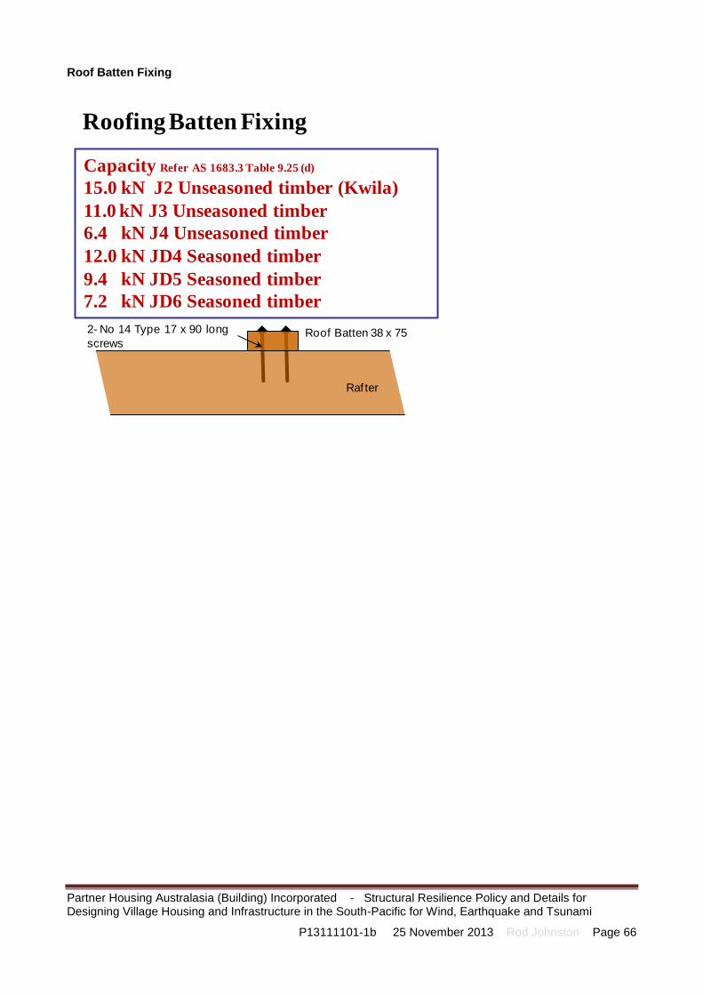
Partner Housing Australasia (Building) Incorporated - Structural Resilience Policy and Details for Designing Village Housing and Infrastructure in the South-Pacific for Wind, Earthquake and Tsunami
P13111101-1b 25 November 2013 Rod Johnston Page 66
Roof Batten Fixing
Roofing Batten Fixing
Capacity Refer AS 1683.3 Table 9.25 (d)
15.0 kN J2 Unseasoned timber (Kwila)
11.0 kN J3 Unseasoned timber
6.4 kN J4 Unseasoned timber
12.0 kN JD4 Seasoned timber
9.4 kN JD5 Seasoned timber
7.2 kN JD6 Seasoned timber
2- No 14 Type 17 x 90 long
screws
Rafter
Roof Batten 38 x 75

Partner Housing Australasia (Building) Incorporated - Structural Resilience Policy and Details for Designing Village Housing and Infrastructure in the South-Pacific for Wind, Earthquake and Tsunami
P13111101-1b 25 November 2013 Rod Johnston Page 67
Roof Batten Fixing
Capacity 13 kN Refer AS 1683.3 Table 9.25 (g)
30 x 0.8 mm galvanised steel strap looped over
batten and under the raf ter, and each end f ixed by
5-30 x 2.8 mm φ galvanised f lat-head nails (f ixed into
unspecif ied raf ter timber), OR 3-30 x 2.8 mm φgalvanised f lat-head nail f ixed into Kwila [J2] raf ter.
Nominal nailing
Rafter
Roof Batten
Roofing Batten Fixing

Partner Housing Australasia (Building) Incorporated - Structural Resilience Policy and Details for Designing Village Housing and Infrastructure in the South-Pacific for Wind, Earthquake and Tsunami
P13111101-1b 25 November 2013 Rod Johnston Page 68
Roof Fixings and Cyclone Washers
Roof Fixings and Cyclone Washers
AS 4055 Wind Classification N1 N2 N3 N4 C1 N5 C2 N6 C3 C4
Maximum end span without cyclone washers 900 750 Not suitable Not suitable
Maximum end span with cyclone washers 1,200 900 Not suitable Not suitable
Number of ribs to be fixed Every second rib Every rib Every rib Not suitable Not suitable
Maximum internal span without cyclone washers 900 750 Not suitable Not suitable
Maximum internal span with cyclone washers 1,200 900 Not suitable Not suitable
Number of ribs to be fixed Every third rib Every rib Every rib Not suitable Not suitable
950
1,200
Notes:
1. In some cirmstances, engineering analysis of test results may give improved spans.
2. Refer to roofing manufacturer's technical manuals for specification of fixing screws, details and material compatibility.
3. References include: Lysaghts "Cyclonic Area Design Manual". http://www.lysaght.com/roofing
Suitable Spans and Fixing Arrangemetns of
Corrugated Steel Sheeting (0.42 mm BMT)

Partner Housing Australasia (Building) Incorporated - Structural Resilience Policy and Details for Designing Village Housing and Infrastructure in the South-Pacific for Wind, Earthquake and Tsunami
P13111101-1b 25 November 2013 Rod Johnston Page 69
“Fishtail” Roof Anchors for Reinforced Concrete Masonry Bond Beams
Nominal 390 x 190 x 190 mm
reinforced hollow concrete
masonry
M16 bolted connection in
accordance with AS 1684
50 x 6 Plate x 460 long
Hot dip galvanised
N12 or N16 horizontal steel
reinforcement grouted within the
bond beam, tied by N12 or N16
reinforcing bars to starter bars in
concrete slab-on-ground
“Fishtail” Roof Anchors for Reinforced Concrete Masonry Bond Beams
50 x 6 Plate x 460 long
Hot dip galvanised
25
50
30
460
f sy = 250 MPa
Form a “f ish tail” by
bending each side of
the cleat though 30o.
200
25
30
200
Capacity
190 mm reinforced masonry 30 .7 kN
140 mm reinforced masonry 23.3 kNBased on AS 4773.1 Table 6.2

Partner Housing Australasia (Building) Incorporated - Structural Resilience Policy and Details for Designing Village Housing and Infrastructure in the South-Pacific for Wind, Earthquake and Tsunami
P13111101-1b 25 November 2013 Rod Johnston Page 70
“Single” Roof Anchors for Reinforced Concrete Masonry Bond Beams
“Single” Roof Anchors for Reinforced Concrete Masonry Bond Beams
Nominal 390 x 190 x 190 mm
reinforced hollow concrete
masonry
M16 bolted connection in
accordance with AS 1684
50 x 6 Plate x 260 long
Hot dip galvanised
N12 or N16 horizontal steel
reinforcement grouted within the
bond beam, tied by N12 or N16
reinforcing bars to starter bars in
concrete slab-on-ground
50 x 6 Plate x 260 long
Hot dip galvanised
25
50
30
260
f sy = 250 MPa
2 Holes 20 mm
diameter200
25
30
Capacity
190 mm reinforced masonry 13.1 kN
140 mm reinforced masonry 11.3 kNBased on AS 4773.1 Table 6.2

Partner Housing Australasia (Building) Incorporated - Structural Resilience Policy and Details for Designing Village Housing and Infrastructure in the South-Pacific for Wind, Earthquake and Tsunami
P13111101-1b 25 November 2013 Rod Johnston Page 71
Appendix 1 – Cyclone Categories The information below on tropical cyclones is reproduced from the following Bureau of Metrology web site: http://www.bom.gov.au/cyclone/about/intensity.shtml
Tropical Cyclone Intensity
Tropical cyclone intensity is defined by the maximum mean wind speed over open flat land or water. This is sometimes referred to as the maximum sustained wind and will be experienced around the eye-wall of the cyclone.
Mean Wind: In most of the world the mean wind speed is defined as the wind speed averaged over a period of 10 minutes. It should be measured at 10 m above the surface. The major exception is the USA where they use a 1-minute average.
Wind Gust: In most of the world the wind gust speed is defined as the wind speed averaged over 2 or 3 seconds (in Australia we use 3 seconds).
Typically gusts over open land will be about 40% greater than the mean wind and gusts over the ocean will be 25 - 30% greater than the mean wind. It is often the stronger gusts that cause the most significant damage to buildings
While a cyclone advice may refer to a certain maximum sustained wind or gust, there will be localised points where the winds will exceed this value, particularly in gullies, about ridges and between buildings where winds can be funnelled by the landscape.
Extent of Significant Winds
The extent of damaging winds will vary between cyclones. More importantly, the most severe winds will be confined to a small area around the outside of the eye. Often people will experience the winds in the outer part of a Category 4 or 5 cyclone. They will believe that they have experienced a major cyclone, yet the winds may have only been Cat 1 or 2 strength.
It is important to recognise the structure of a cyclone when assessing past experience. This will make a future direct hit less of a surprise.
Tropical Cyclone Category System
CATEGORY 1 (tropical cyclone) – Negligible house damage. Damage to some crops, trees and caravans. Craft may drag moorings. A Category 1 cyclone's strongest winds are GALES with typical gusts over open flat land of 90 - 125 km/h. These winds correspond to Beaufort 8 and 9 (Gales and strong gales).
CATEGORY 2 (tropical cyclone) – Minor house damage. Significant damage to signs, trees and caravans. Heavy damage to some crops. Risk of power failure. Small craft may break moorings. A Category 2 cyclone's strongest winds are DESTRUCTIVE winds with typical gusts over open flat land of 125 - 164 km/h. These winds correspond to Beaufort 10 and 11 (Storm and violent storm).

Partner Housing Australasia (Building) Incorporated - Structural Resilience Policy and Details for Designing Village Housing and Infrastructure in the South-Pacific for Wind, Earthquake and Tsunami
P13111101-1b 25 November 2013 Rod Johnston Page 72
CATEGORY 3 (severe tropical cyclone) – Some roof and structural damage. Some caravans destroyed. Power failures likely. A Category 3 cyclone's strongest winds are VERY DESTRUCTIVE winds with typical gusts over open flat land of 165 - 224 km/h. These winds correspond to the highest category on the Beaufort scale, Beaufort 12 (Hurricane).
CATEGORY 4 (severe tropical cyclone) – Significant roofing loss and structural damage. Many caravans destroyed and blown away. Dangerous airborne debris. Widespread power failures. A Category 4 cyclone's strongest winds are VERY DESTRUCTIVE winds with typical gusts over open flat land of 225 - 279 km/h. These winds correspond to the highest category on the Beaufort scale, Beaufort 12 (Hurricane).
CATEGORY 5 (severe tropical cyclone) – Extremely dangerous with widespread destruction. A Category 5 cyclone's strongest winds are VERY DESTRUCTIVE winds with typical gusts over open flat land of more than 280 km/h. These winds correspond to the highest category on the Beaufort scale, Beaufort 12 (Hurricane). The Beaufort Scale
Beaufort scale
Cyclone category
Average wind
speed (knots)
Average wind
speed (km/h)
Estimating speed over land
Estimating speed over water
0 Calm Less than 1
less than 1
Calm, smoke rises vertically.
Sea like mirror
1 Light Air 1 - 3 1 - 5
Direction of wind shown by smoke drift, but not by wind vanes.
Ripples with the appearance of scales are formed, but without foam crests
2 Light breeze
4 - 6 6 - 11
Wind felt on face; leaves rustle; ordinary wind vane moved by wind.
Small wavelets, still short, but more pronounced; crests have a glassy appearance and do not break
3 Gentle breeze
7 - 10 12 - 19
Leaves and small twigs in constant motion; wind extends light flag.
Large wavelets; crests begin to break; foam of glassy appearance; perhaps scattered white horses
4 Moderate breeze
11 - 16 20 - 28 Raises dust and loose paper; small branches moved.
Small waves, becoming longer; fairly frequent white horses
5 Fresh breeze
17 - 21 29 - 38
Small trees in leaf begin to sway; crested wavelets form on inland waters.
Moderate waves, taking a more pronounced long form; many white horses are formed (chance of some spray)
6 Strong breeze
22 - 27 39 - 49
Large branches in motion; whistling heard in telegraph wires; umbrellas used with difficulty.
Large waves begin to form; the white foam crests are more extensive everywhere (probably some spray)
7 Near gale 28 - 33 50 - 61
Whole trees in motion; inconvenience felt when walking against the wind.
Sea heaps up and white foam from breaking waves begins to be blown in streaks along the direction of the wind

Partner Housing Australasia (Building) Incorporated - Structural Resilience Policy and Details for Designing Village Housing and Infrastructure in the South-Pacific for Wind, Earthquake and Tsunami
P13111101-1b 25 November 2013 Rod Johnston Page 73
Beaufort scale
Cyclone category
Average wind
speed (knots)
Average wind
speed (km/h)
Estimating speed over land
Estimating speed over water
8 Gale 1 34 - 40 62 - 74 Breaks twigs off trees; generally impedes progress.
Moderately high waves of greater length; edges of crests begin to break into the spindrift; the foam is blown in well-marked streaks along the direction of the wind
9 Strong gale
1 41 - 47 75 - 88
Slight structural damage occurs (chimney pots and slates removed).
High waves; dense streaks of foam along the direction of the wind; crests of waves begin to topple, tumble and roll over; spray may affect visibility
10 Storm 2 48 - 55 89 - 102
Seldom experienced inland; trees uprooted; considerable structural damage occurs.
Very high waves with long overhanging crests; the resulting foam, in great patches, is blown in dense white streaks along the direction of the wind; on the whole, the surface of the sea takes a white appearance; the tumbling of the sea becomes heavy and shock-like; visibility affected
11 Violent storm
2 56 - 63 103 - 117
Very rarely experienced; accompanied by widespread damage.
Exceptionally high waves (small and medium sized ships might be for a time lost to view behind the waves); the sea is completely covered with long white patches of foam lying along the direction of the wind; everywhere the edges of the wave crests are blown into froth; visibility affected
12 Hurricane 3,4,5 64 and over
118 and over
Severe and extensive damage.
The air is filled with foam and spray; sea completely white with driving spray; visibility very seriously affected
Global Tropical Cyclone Terminology
Tropical cyclones can be defined in different ways elsewhere in the world. Often news reports from the United States or Asia will refer to hurricanes or typhoons. These are all tropical cyclones, but with different names. While the category definitions are not identical, the following provides an approximate guide for comparison
Australian name
Australian category
US*
US Saffir-Simpson category
scale*
NW Pacific Arabian Sea
/Bay of Bengal
SW Indian Ocean
South Pacific (East
of 160E)
Tropical low - Tropical depression
- Tropical depression
Depression or severe depression
Tropical depression
Tropical depression
Tropical cyclone
1 Tropical storm
- Tropical storm
Cyclonic storm
Moderate tropical storm
Tropical cyclone (Gale)
Tropical 2 Tropical - Severe tropical
Severe Severe Tropical cyclone

Partner Housing Australasia (Building) Incorporated - Structural Resilience Policy and Details for Designing Village Housing and Infrastructure in the South-Pacific for Wind, Earthquake and Tsunami
P13111101-1b 25 November 2013 Rod Johnston Page 74
cyclone storm storm cyclonic storm tropical storm (Storm)
Severe tropical Cyclone
3 Hurricane 1 Typhoon Very severe cyclonic storm
Tropical cyclone
Tropical cyclone (Hurricane)
Severe tropical cyclone
4 Hurricane 2 - 3 Typhoon Very severe cyclonic storm
Intense tropical cyclone
Tropical cyclone (Hurricane)
Severe tropical cyclone
5 Hurricane 4 - 5 Typhoon Super cyclonic storm
Very intense tropical cyclone
Tropical cyclone (Hurricane)
* Note that the USA uses 1-minute wind averages, which are generally greater than 10-minute wind averages used elsewhere in the world – hence their intensity definitions (wind strengths) will differ by about 10%.