Structural Plan Review Walls and Bracing Lesson 6 · positions marked W1, ... spacing Sheathing...
72
Structural Plan Review Walls and Bracing Lesson 6 Updated: March 2017
-
Upload
dinhkhuong -
Category
Documents
-
view
218 -
download
0
Transcript of Structural Plan Review Walls and Bracing Lesson 6 · positions marked W1, ... spacing Sheathing...

Structural Plan Review
Walls and Bracing
Lesson 6
Updated: March 2017

2 of 72
Headers

3 of 72
Header Size Determination
Based on floor design
Use Table R502.5(1) for headers in exterior walls
Use Table R502.5(2) for interior walls

of 72 4
Headers
• Table R502.5(1) exterior bearing walls
• Table R502.5(2) interior bearing walls

5
of 72
Headers
5
Exterior
walls
Interior
walls
6 of 72
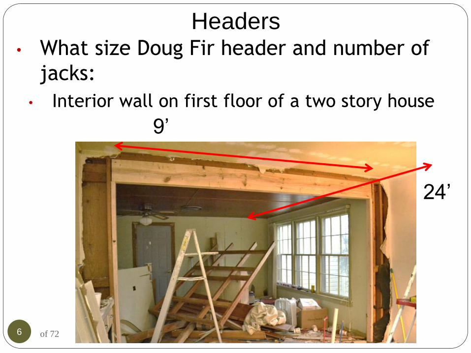
Headers • What size Doug Fir header and number of
jacks:
• Interior wall on first floor of a two story house
9’
24’

7
of 72
Headers - answer
Supports one floor
8 of 72
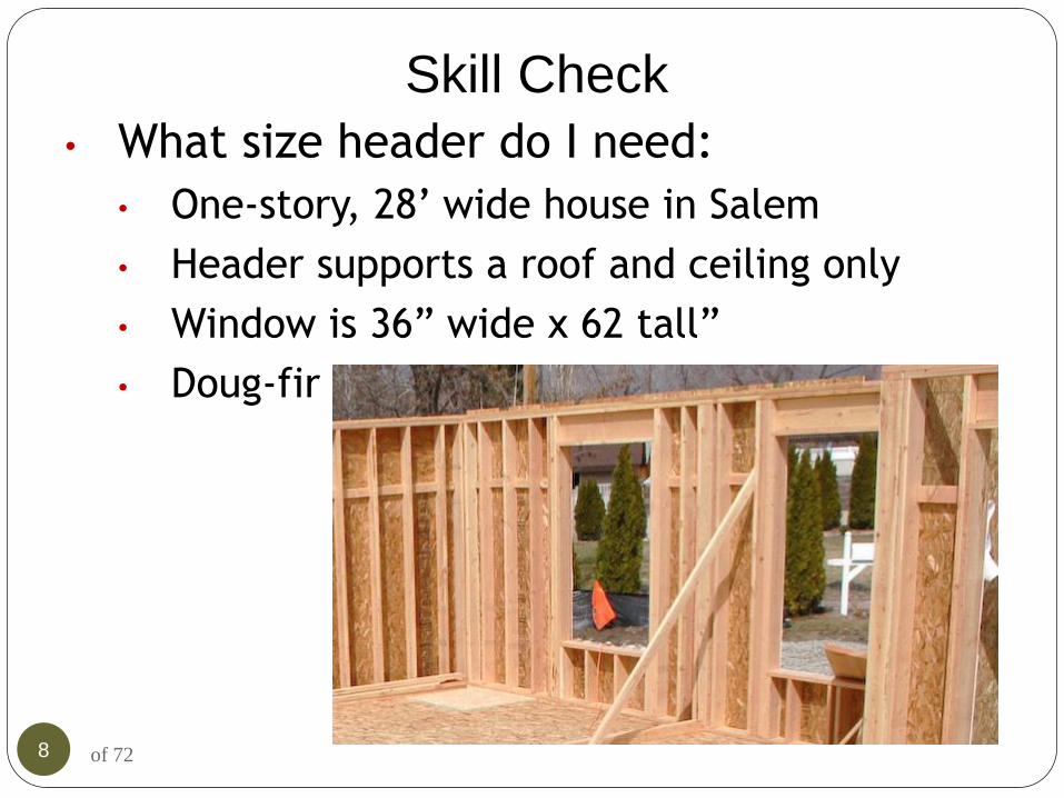
Skill Check
• What size header do I need:
• One-story, 28’ wide house in Salem
• Header supports a roof and ceiling only
• Window is 36” wide x 62 tall”
• Doug-fir

9
of 72
Skill Check - answer
• One-story, 28’ wide house in Salem
• Header supports a roof and ceiling only
• Window is 36” wide x 62 tall”
• Hem-fir

10 of 72
Skill Check
• What is the minimum size header over
the window?
• House is 36’ wide
• The 2nd floor joists
bear on center wall
and rear wall.
• 25 psf snow load
• Window is 8’wide

11 of 72
Skill Check -answer
12 of 72
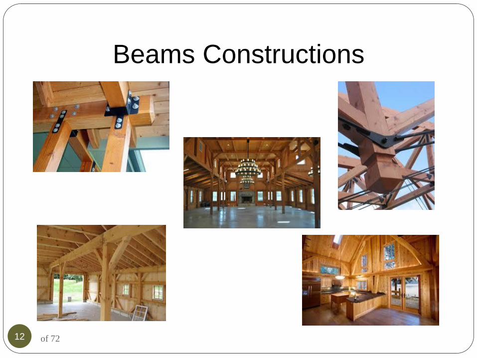
Beams Constructions

13 of 72
Beam Design Assumptions Know structural theory
Knowledge of arithmetic and
basic algebra
Simple loading criteria
Uniform loads
Beam simple span
Shear will not to govern
Allowable stress design
Wood and LVL only

14 of 72
Beam Load Calculations
In the field of construction, beam load
calculations can become truly critical
A simple yet effective way of calculating beam
loads is discussed here through derived formulas
and expressions

15
Point load: A load or weight subjected over a point
area is called a point load. However, mathematically a
point load doesn’t look feasible, simply because any
load will need to have a certain area of impact and
cannot possibly balance over a point, but if the impact
area is to small compared to the length of the beam,
may be taken as defined.
of 72

16
Equally Distributed load: As the name implies a
load that’s equally aligned across the whole beam is
termed an equally distributed load.
of 72
of 72 17
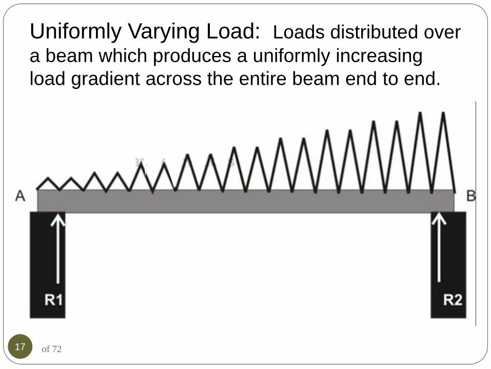
Uniformly Varying Load: Loads distributed over
a beam which produces a uniformly increasing
load gradient across the entire beam end to end.

18 of 72
Beam Reaction
Referring to the diagram
alongside, let’s consider
a beam being supported
at its ends (left and
right), denoted by the
letters A and B

19 of 72
Now, there are primarily a couple of forces ( turning effect ) that’s
acting over the beam ends A and B, clockwise and counter-
clockwise moment of force
Let there be point loads acting on the beam over
positions marked W1, W2 and W3.
Also let: Ra = Reaction at the end A of the beam
Rb = Reaction at the end B of the beam

20 of 72
Since the moment of force over a supported beam is
equal to the point load (weight here) and its distance from
the support or the pivot, total clockwise moment acting at
point A may be given as:
(W1 x a) + (W2 x b) + (W3 x c)
Also, the counter-clockwise moment of force acting over
point B must be: Rb x I

21 of 72
Now, because the beam is in equilibrium, implies that the two moments
of force must be equal in magnitudes, therefore equating the two
expressions gives:
(W1 x a) + (W2 x b) + (W3 x c) = Rb x L
Rb = (W1 x a) + (W2 x b) + (W3 x c)/I
The equilibrium with the beam also implies that:
Ra + Rb = 2 [ (W1 x a) + (W2 x b) + (W3 x c)] / L

22 of 72
Now as per the conditions of equilibrium, the algebraic
sum of all horizontal components in the above expression
becomes immaterial and can be nullified.
Therefore, the final equation becomes
Ra = (W1 + W2 + W3) - Rb

23
of 72
Skill Check
• How many 2x4 jack studs
would I need under this beam?

24 of 72
Skill Check - answer
• How many 2x4 jack studs would I need
under this beam?
9’
2k 4k 6k 8k 10k
2 x 4

25 of 72
Columns and Supports

26 of 72
Columns
9’
3.3k 6.6k 10k
2 x 6
9’
2k 4k 6k 8k 10k
2 x 4
Rule of thumb

27 of 72
Skill Check
• What size
posts
would I
expect? PB02 (12)

28 of 72
Columns
> 10k use manufactured lumber

29 of 72
Skill Check - answer
• What size
posts
would I
expect?
• 9’ column PB02 (12)

30 of 72
Skill Check
• What is the maximum wall height allowed?
• 2x4 walls with continuous OSB sheathing

31 of 72
Skill Check - answer
• What is the maximum wall height
allowed?
• 2x4 walls with continuous OSB
sheathing and a CS-PF header
32 of 72
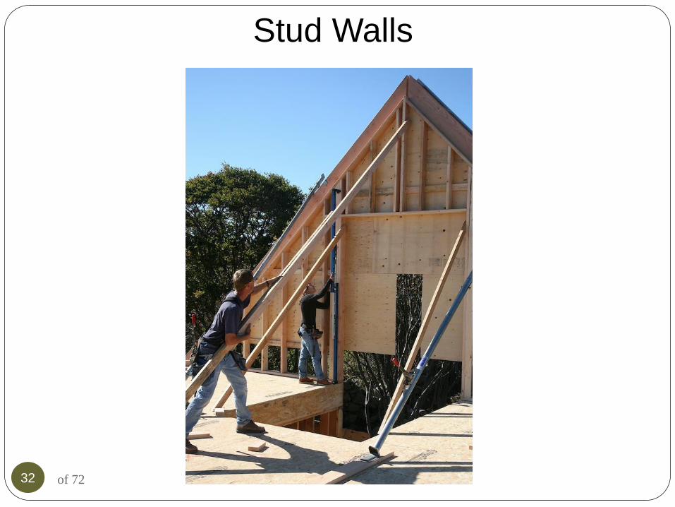
Stud Walls

33 of 72
Wall Systems
• Topics
• Stud walls
• Wall height
• Tall walls
• Wall bracing
• Headers
• Lintels
• Columns
• Wall coverings

34 of 72
Tall Walls
Section R602.3.1
Size, height and spacing
Maximum Height:
Table R602.3.1
Tall Wall Conditions:
Wind speeds 110 mph
Grade #2 or better
Snow load ≤ 25 PSF
Joist, rafter and truss
span ≤ 12’

35 of 72
Tall Walls
• What if the tall walls are carrying more
than 6’ of tributary area?

36 of 72
Wall Stud Design Check
Studs must be continuous from sole to top plate
Standard grade and higher, use Table R602.3(5)
Utility grade restricted to:
16” maximum spacing
Supports roof/ceiling only
Maximum height:
8’ load bearing walls
8’ exterior walls
10’ non-load bearing walls

37 of 72
Wall Stud Design Seismic Design Categories A, B, C, D and D(2)

38 of 72
Story Height

39 of 72
Stud Wall Species and Grades
R602.2
SELECT STRUCTURAL
#1
#2
#3
STUD
CONSTRUCTION
STANDARD
UTILITY
NO
T A
S G
OO
D
BE
TT
ER

40 of 72
Stud - Size, Height, Spacing
Table R602.3(5)

41 of 72
Stud - Size, Height, Spacing
12-0” MAX STUD HT
11’-7” MAX FLOOR - FLOOR HT

42 of 72
R301.3 Story Height Maximum story height = 11'-7"
I-joists floor joists
11'-7"
max.

43 of 72
Stud - Size, Height, Spacing

44 of 72
The Habitable Attic
Using Table R602.3(5), determine the stud size of
the walls highlighted below.
1st floor
Walkout basement

45 of 72
The Habitable Attic Walkout basement:
Supporting, two floors & habitable attic
Required studs = 2x6@16"o.c.

46 of 72
The Habitable Attic
1st floor:
Supporting, one floors & habitable
attic
Required studs = 2x6@24"o.c. min.
Table
R602.3(5)

47 of 72
Skill Check What size of studs are required for each floor?
Habitable attic trusses span 34’

48 of 72
Skill Check - answer What size of studs are required for each floor?

49 of 72
Wall Coverings
• Scenario:
• Customer calls and
says contractor did
not put Tyvek
under the vinyl
siding.
• Is it required?
• Cite the code
reference.

50 of 72
Wall Coverings - answer
R 703.2 and R 703.1.1

51 of 72
Wall Construction and bracing
52 of 72
Objectives
Determine stud size and spacing for vertical load.
Determine compliance alternatives for resistance of
horizontal load.

53 of 72 Fig. R602.3(1)

54 of 72
KING STUDS
Fig. R602.3(2)

55 of 72
Understanding Basics of Bracing
Basic provisions of Lesson 4:
The basic provisions of lesson 4 will cover the bracing provisions
in Chapter 6 for the basic dwelling unit. The module will move
through the code provisions in R602.10 and other related
provisions in non-sequential order as they apply to structural
bracing.
What is bracing?
Bracing is the structural component of a building that resists the
lateral forces imposed on the structure by wind or seismic events.
Bracing is typically part of the vertical wall framing system and
can be sections of wall that are sheathed with plywood, gypsum
board, fiberboard, cement plaster and carious other materials.
The walls resist lateral forces through their attachment to the
roof, floor, and foundation structures.

56 of 72

57 of 72
The Lateral Load Path As we learned in Lesson 3 all buildings
must be braced to resist the lateral loads
due to wind and seismic. Wall
construction must include bracing to
resist imposed lateral loads
resulting from wind or seismic
loading and to provide stability
to the structure. When subjected
to wind loads, the upper portion of the
structure moves horizontally while the
lower portion is restrained at ground level.
During an earthquake, the
ground motion displaces the
foundation while the top portion
of the structure tries to remain
stationary. In both of these cases
the bracing resists the differential
movement and thus prevents or
limits damage to the building.

58 of 72
The Lateral Load Path cont.
A typical residential structure experiences lateral loading starting at the roof
sheathing that transfers the load to the rafters/trusses then through the double top
plate to the wall studs to the sole plate to the floor sheathing to the rim joists/floor
joists to the mud sill to the foundation stem wall to the supporting soil. In either
the wind or seismic loading condition the walls will distribute one-half of the wall
height load into the double top plate and the lower half of the wall will transfer
loading directly into the foundation
system. The lower half wall loading
will not affect the forces being
transferred into the brace/shear
walls. In the seismic loading
condition the weight of the endwalls
will be added to the forces going
into the brace/shear walls. With
this understanding it is time to
adventure into the world of wall
bracing in Section R602.10 of the
Residential Code.

59 of 72
Table R602.3(5) – Bearing Wall
Known values:
Stud size
Stud height
Story level

60 of 72
Table R602.3(5) – Non-bearing Wall
Known value:
Stud size
Stud height

61 of 72
Wall Bracing

62 of 72
Wall Bracing
Section R602.10,
“Prescriptive” Wall Bracing
Section R602.12, “Any
additional” Wall Bracing
Other wall bracing:
Engineered solutions
Proprietary products

63 of 72
“Classic” Wall Bracing
Section R602.10.
Prescriptive solution.
Based on:
Braced wall panels
Braced wall lines.

64 of 72
Braced Wall Panels
Full height of wall.
Minimum length.
(Based on sheathing and
material type.)
Length
Heig
ht

65 of 72
Braced Wall Panels
Full height of wall.
Minimum length.
(Based on sheathing and
material type.)
Vertical, horizontal joints
permitted.
Multiple
pieces of
sheathing
allowed

66 of 72
Braced Wall Lines
Straight lines
In each plan
direction
Permitted to “float”
At each floor
B C
2
1
A

67 of 72
Prescriptive Bracing Types
Intermittent bracing
Sheath at BWP locations
only
Continuous sheathing
Sheath all exposed areas

68 of 72
Continuous Sheathing Methods
CS-WSP: wood
structural panels.
CS-SFB: structural
fiberboard
CS-G: wood structural
panels at garage.
CS-PF: wood structural
panel portal frame.

69 of 72
Engineered Shear Walls
Stud size, spacing
Sheathing type, thickness
Fastening schedule
Hold-down requirement,
capacity
Anchor bolt location,
capacity
length
he
igh
t
stud
size
sheathing
thickness
anchor
bolts
hold-down
capacity
edge,
field
nailing

70 of 72
Wall Bracing
• Two methods of analysis
3
2 1
4
R602.10.2
Intermittent
Method
R602.10.4
Continuously
Sheathed Method

71 of 72
Review Lesson 4: Wall Systems
Topics:
1. Stud walls
a) Wall height
b) Tall walls
2. Wall bracing
3. Headers
4. Lintels
5. Columns
6. Wall coverings

72 of 72