Structural NDE of concrete structures using protected EFPI and FBG sensors
8
Sensors and Actuators A 126 (2006) 340–347 Structural NDE of concrete structures using protected EFPI and FBG sensors J.S. Leng a,∗ , R.A. Barnes b , A. Hameed b , D. Winter b , J. Tetlow b , G.C. Mays b , G.F. Fernando b a Centre for Composite Materials and Structures, P.O. Box 3011, No. 2 Yi Kuang Street, HIT Science Park, Harbin Institute of Technology, Harbin 150001, PR China b Royal Military College of Science (RMCS), Defence Academy of the United Kingdom, Cranfield University, Shrivenham, Wiltshire SN6 8LA, UK Received 28 February 2005; received in revised form 19 October 2005; accepted 27 October 2005 Available online 7 December 2005 Abstract This paper is concerned with the design concepts, modelling and implementation of various fibre optic sensor protection systems for devel- opment in concrete structures. The design concepts of fibre optic sensor protection system and on-site requirements for surface-mounted and embedded optical fibre sensor in concrete structures have been addressed. The aspects of finite element (FE) modelling of selected sensor pro- tection systems in terms of strain transfer efficiency from the structure to the sensing region have also been focused in this paper. Finally, the experimental validations of specified sensor protection system in concrete structures have been performed successfully. Protected extrinsic Fabry–Perot interferometric (EFPI) and fibre Bragg grating (FBG) sensors have been used to monitor the structural health status of plain and composite wrapped concrete cylinders. Results obtained indicate that the protection system for the sensors performs adequately in concrete envi- ronment and there is very good correlation between results obtained by the protected fibre optic sensors and conventional electrical resistance strain gauges. © 2005 Published by Elsevier B.V. Keywords: Fibre optic sensor (FOS); Sensor protection system (SPS); Concrete structures; Extrinsic Fabry–Perot interferometric sensor (EFPI); Fibre Bragg grating (FBG); Non-destructive evaluation (NDE); Smart structures 1. Introduction The structural non-destructive evaluation (NDE) in-service is very important and definitely demanded for safely working of engineering structure such as concrete structures. It is very difficult to carry out by using conventional methods. New rein- forced concrete construction would benefit greatly from in situ structural monitors that could detect a decrease in performance or imminent failure, for example, variation in strain, temper- ature, corrosion or crack formation. The ability to interrogate numerous sensors multiplexed along a single fibre permits an entire structure to be outfitted with sensors with a manageable number of leads routed to central access points. In response to the increased need, various techniques are being developed and ∗ Corresponding author. Tel.: +86 45186402328; fax: +86 45186402328. E-mail address: [email protected] (J.S. Leng). some of the most promising are based on the use of fibre optic sensors (FOS) [1]. Fibre optic smart structure is a new concept that will allow engineers to add a neural system to their designs, enabling dam- age assessment, vibration damping and many other capabilities to structures that would be very difficult to achieve by other means. The potential market for the application of smart civil structures can be quite large. The most probable candidates will be smart civil structures such as smart skyscrapers, smart bridges, dams, decks, etc. Fibre optic sensors can offer many potential advantages for application in civil structural systems. In fact, a lot of fibre optic sensors have been developed for use in smart civil structures, for example, polarisation FOS, extrin- sic Fabry–Perot interferometric (EFPI), fibre Bragg gratings (FBGs), multimode FOS, etc. [1–8]. However, the vulnerabil- ity of fibre optic sensor makes it is very difficult to protect the fibre from concrete aggregate in the pour duration. Therefore, the FOS could be very easy to be damaged and corroded during 0924-4247/$ – see front matter © 2005 Published by Elsevier B.V. doi:10.1016/j.sna.2005.10.050
Transcript of Structural NDE of concrete structures using protected EFPI and FBG sensors

Sensors and Actuators A 126 (2006) 340–347
Structural NDE of concrete structures usingprotected EFPI and FBG sensors
J.S. Lenga,∗, R.A. Barnesb, A. Hameedb, D. Winterb,J. Tetlowb, G.C. Maysb, G.F. Fernandob
a Centre for Composite Materials and Structures, P.O. Box 3011, No. 2 Yi Kuang Street, HIT Science Park,Harbin Institute of Technology, Harbin 150001, PR China
b Royal Military College of Science (RMCS), Defence Academy of the United Kingdom, Cranfield University,Shrivenham, Wiltshire SN6 8LA, UK
Received 28 February 2005; received in revised form 19 October 2005; accepted 27 October 2005Available online 7 December 2005
Abstract
This paper is concerned with the design concepts, modelling and implementation of various fibre optic sensor protection systems for devel-o ounted ande d sensor pro-t er. Finally,t ted extrinsicF f plain andc oncrete envi-r istance strag©
K ragg(
1
iodfsoanent
optic
llowdam-ilities
thercivilidatesmartmanyms.r usetrin-ingsl-thefore,uring
0d
pment in concrete structures. The design concepts of fibre optic sensor protection system and on-site requirements for surface-mmbedded optical fibre sensor in concrete structures have been addressed. The aspects of finite element (FE) modelling of selecte
ection systems in terms of strain transfer efficiency from the structure to the sensing region have also been focused in this paphe experimental validations of specified sensor protection system in concrete structures have been performed successfully. Protecabry–Perot interferometric (EFPI) and fibre Bragg grating (FBG) sensors have been used to monitor the structural health status oomposite wrapped concrete cylinders. Results obtained indicate that the protection system for the sensors performs adequately in conment and there is very good correlation between results obtained by the protected fibre optic sensors and conventional electrical resinauges.2005 Published by Elsevier B.V.
eywords: Fibre optic sensor (FOS); Sensor protection system (SPS); Concrete structures; Extrinsic Fabry–Perot interferometric sensor (EFPI); Fibre BgratingFBG); Non-destructive evaluation (NDE); Smart structures
. Introduction
The structural non-destructive evaluation (NDE) in-services very important and definitely demanded for safely workingf engineering structure such as concrete structures. It is veryifficult to carry out by using conventional methods. New rein-
orced concrete construction would benefit greatly from in situtructural monitors that could detect a decrease in performancer imminent failure, for example, variation in strain, temper-ture, corrosion or crack formation. The ability to interrogateumerous sensors multiplexed along a single fibre permits anntire structure to be outfitted with sensors with a manageableumber of leads routed to central access points. In response to
he increased need, various techniques are being developed and
∗ Corresponding author. Tel.: +86 45186402328; fax: +86 45186402328.E-mail address: [email protected] (J.S. Leng).
some of the most promising are based on the use of fibresensors (FOS)[1].
Fibre optic smart structure is a new concept that will aengineers to add a neural system to their designs, enablingage assessment, vibration damping and many other capabto structures that would be very difficult to achieve by omeans. The potential market for the application of smartstructures can be quite large. The most probable candwill be smart civil structures such as smart skyscrapers, sbridges, dams, decks, etc. Fibre optic sensors can offerpotential advantages for application in civil structural systeIn fact, a lot of fibre optic sensors have been developed foin smart civil structures, for example, polarisation FOS, exsic Fabry–Perot interferometric (EFPI), fibre Bragg grat(FBGs), multimode FOS, etc.[1–8]. However, the vulnerabiity of fibre optic sensor makes it is very difficult to protectfibre from concrete aggregate in the pour duration. Therethe FOS could be very easy to be damaged and corroded d
924-4247/$ – see front matter © 2005 Published by Elsevier B.V.oi:10.1016/j.sna.2005.10.050

J.S. Leng et al. / Sensors and Actuators A 126 (2006) 340–347 341
Fig. 1. Schematic illustration of the steel tube-based ESPS: (1) Optical fibre, (2) silicone rubber, (3) thick PTFE tube, (4) steel flange, (5) steel tube, (6) sensorelement, (7) epoxy adhesive, (8) thin PTFE tube and (9) fixed steel tube.
the practical application of long term. This reason really limitsthe application of fibre optic sensor in concrete structures.
There are few types of protected fibre optic sensors are usedin concrete structures by previously researchers[9–12]. Nor-mally, the FOSs are covered by steel sheet, steel tube and siliconerubber. Previously researchers also performed mechanical mea-surement of concrete structures with embedded protected FOS[10–17].
In this paper, two kinds of protection system of fibre optic sen-sors that are surface-mounted and embedded protection systemhave been developed. Furthermore, experiments of structuralhealth monitoring based on plain and composite wrapped con-crete cylinders also have been performed by using protectedFOS. The results indicate that the FOSs had been protected verywell. Furthermore, the results gave very good accordance com-paring with the results of related reference electrical resistancestrain (ERS) gauges.
2. Concept of sensor protection system (SPS) of fibreoptic sensor
The primary requirements for the sensor protection sys-tem are protection of the silica fibres from the alkaline envi-ronment and protection of the sensor system: (a) during theconcrete pouring operation and (b) against mechanical or abra-s ggrs mus
ensure good transduction for the measurement of interest; inthis paper, embedded sensor protection system (ESPS) andsurface-mountable sensor protection system (SSPS) have beendeveloped.
2.1. Embedded sensor protection systems
For the embedded sensor protection system, the strain transferis a most important issue aside from the protection of sensors. Toget best strain transfer between the sensor and protection system,three types of ESPS are designed in this paper, respectively,which is ESPS based on metal, ESPS based on CFRP compositeand ESPS based on concrete materials. In fact, these ESPSs havedifferent application fields.
2.1.1. Metal-based ESPSFig. 1shows the schematic illustration of the steel tube-based
embedded sensor protection system. Photograph of steel tube-based ESPS is shown inFig. 2.
ion damage caused by the aggregates and against any aive chemical environments. The sensor system also
Fig. 2. Photograph of the steel tube-based ESPS.
es-t
Fig. 3. Schematic illustration of the rebar-based ESPS.
342 J.S. Leng et al. / Sensors and Actuators A 126 (2006) 340–347
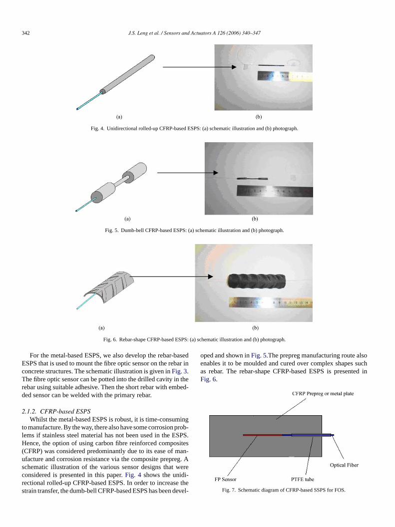
Fig. 4. Unidirectional rolled-up CFRP-based ESPS: (a) schematic illustration and (b) photograph.
Fig. 5. Dumb-bell CFRP-based ESPS: (a) schematic illustration and (b) photograph.
Fig. 6. Rebar-shape CFRP-based ESPS: (a) schematic illustration and (b) photograph.
For the metal-based ESPS, we also develop the rebar-basedESPS that is used to mount the fibre optic sensor on the rebar inconcrete structures. The schematic illustration is given inFig. 3.The fibre optic sensor can be potted into the drilled cavity in therebar using suitable adhesive. Then the short rebar with embed-ded sensor can be welded with the primary rebar.
2.1.2. CFRP-based ESPSWhilst the metal-based ESPS is robust, it is time-consuming
to manufacture. By the way, there also have some corrosion prob-lems if stainless steel material has not been used in the ESPS.Hence, the option of using carbon fibre reinforced composites(CFRP) was considered predominantly due to its ease of man-ufacture and corrosion resistance via the composite prepreg. Aschematic illustration of the various sensor designs that wereconsidered is presented in this paper.Fig. 4 shows the unidi-rectional rolled-up CFRP-based ESPS. In order to increase thestrain transfer, the dumb-bell CFRP-based ESPS has been devel-
oped and shown inFig. 5.The prepreg manufacturing route alsoenables it to be moulded and cured over complex shapes suchas rebar. The rebar-shape CFRP-based ESPS is presented inFig. 6.
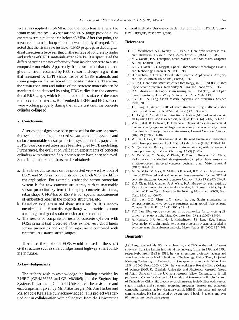
Fig. 7. Schematic diagram of CFRP-based SSPS for FOS.

J.S. Leng et al. / Sensors and Actuators A 126 (2006) 340–347 343
Fig. 8. Flat CFRP composite SSPS: (a) schematic illustration and (b) photograph.
Fig. 9. Curved CFRP composite SSPS: (a) schematic illustration and (b) photograph.
2.2. Surface-mountable SPS
In order to apply the fibre optic sensor on the ageing engi-neering structures, the surface-mountable sensor protection sys-tem has been developed. The surface-mounted SPS can bemade by using the existing techniques and procedures thathave been developed for surface mounting electrical resistancestrain gauges.Fig. 7 presents the schematic diagram of com-posite surface-mountable SPS (CFRP-based SSPS) for FOS.Figs. 8 and 9show the flat and curved CFRP composite SSPS.These devices can be mechanically fastened or bonded to theconcrete structure. The steel tube-based SPS discussed previ-ously can be adapted for retrofitting onto existing ageing struc-tures. Photograph of concrete cylinder with retrofitting SPS isshown inFig. 10.
3. Design of embedded sensor protection system by FEmodelling
For the embedded sensor protection system, a series of SPSswith different shape and size of flanges have been presented.Fig. 11shows the photographs of different type of steel flangesfor the ESPS. In order to evaluation the efficiency of steel flangesfor strain transfer between the sensor and concrete materials, thenon-liner finite element (FE) analysis of concrete cylinder withep indew
The strain results along the SPS–concrete interface of a disc-shape flange having various bond types are shown inFig. 12. Itcan be seen that the strain results are in good agreement with theexperimental and theoretical values irrespective of the type ofbonding between the flanges. The results present that the straincan be transmit across the SPS system. Comparison with theexperimental results, it shows that the maximum difference instrain magnitude is less than 3.5%. For the disc-shape flange
F .
mbedded SPS has been performed in this paper[18]. A com-ressive load of 12.73 MPa was applied on the concrete cylith ESPS.
rig. 10. Photographs of concrete cylinder with retrofitting steel tube SPS

344 J.S. Leng et al. / Sensors and Actuators A 126 (2006) 340–347
Fig. 11. Photographs of different type of steel flanges for ESPS: (a) disc, (b) cone and (c) inverted cone.
Fig. 12. Axial strain in an embedded steel tube with flange for different contact configuration.
with different diameters, the shear stress and strain along theconcrete–SPS interface are shown inFigs. 13 and 14, respec-tively. It can be found that the flange root (base) is under highshear and slippage is clearly occurring in the area before theflange. However, shear stress between the flanges is well withinthe limits. It is clear that the shear stress for the disc type flangehaving a 5 mm diameter gives best results, the overall slippage isleast and a good anchorage is maintained. The strain and stressprofile present that there is not much difference with differentdiameter sand the strain transfer across the interface is goodapproximately 35 mm away from the flanges.
F f steet
4. Experimental validation of protected FOS in concretecylinders
4.1. Plain concrete cylinders with fibre optic sensors
The schematic illustration of experimental set-up of compres-sion test of concrete cylinder with steel tube-based ESPS withEFPI sensor is shown inFig. 15a. The size of concrete cylin-der is 200 mm (length)× 100 mm (diameter). The concrete hasa water/cement ratio of 0.52, an aggregate/cement ratio of 6.Fig. 15b shows the FOS during concrete pour. In fact, the FOSis still working properly after pour and shake duration of con-crete. The strain gauges which have 60 mm length are bonded onthe surface of concrete cylinder by using adhesive AE-10 fromMeasurement Group after surface treatment. The embedded pro-tection system already has been calibrated before embedding itin the concrete cylinder.
The compression test has been carried out in the INSTRON1195. The experimental results of compression test of con-crete cylinder with embedded protection systems compared withresults of electrical resistance strain gauges are shown inFig. 16.Compared the results of FEM with ERS gauges it can be find thatthey have very good agreement. The experimental results alsoshow that the strain from embedded EFPI sensor is a little bitsmaller than FEM and ERS results because there are not 100%strain transfer from concrete materials to protection system.
testo lates
ig. 13. Axial strain at the concrete–tube interface along the tube length oube with disc flanges.
l Fig. 17 is the experimental illustration of compressionf concrete cylinder with CFRP-based SSPS. The CFRP p

J.S. Leng et al. / Sensors and Actuators A 126 (2006) 340–347 345
Fig. 14. Shear stress at the concrete–tube interface along the tube length of steel tube with disc flanges.
Fig. 15. Compression test of concrete cylinder with ESPS: (a) schematic illustration and (b) photograph during the pour.
((00)8) were made in the autoclave by using CFRP prepregs.The EFPI sensors that have 50 mm long capillary and 145�mcavity gap were embedded within the fourth ply and fifth ply.The size of CFRP plate is 145 mm× 20 mm× 1 mm. Then theCFRP protection plates were bond to the concrete cylinder bytwo-component epoxy resin (SIKA 30) which widely used tobond CFRP plates to concrete for strengthening purposes. TheERS gauges were axially bonded on the surface of CFRP plate
Fig. 16. Experimental results of compression test of concrete cylinder embeddedsteel protection systems with EFPI sensor compared with ERS gauge.
as well as concrete surface as the reference source for appliedstrains.
Photograph of concrete cylinder with CFRP-based SSPS isshown inFig. 18. The stress–strain curves for one of surface-mountable CFRP plate compared with that of ERS on the con-crete surface are presented inFig. 19. It is apparent that therewas very good accordance (within 5%) and linear relationshipbetween protected EFPI sensor, ERS on the CFRP surface andERS on the concrete surface. Similar results were obtainedfor the other bonded plates. That also indicates that there isvery effectively strain transfer among CFRP prepregs, protectedCFRP plate and concrete surface.
4.2. CFRP wrapped concrete cylinder with fibre opticsensors
The schematic illustration of CFRP wrapped concrete cylin-der with FOSs and strain gauges was shown inFig. 20. A FBGsensor was surface mounted on the surface of concrete cylin-der in longitudinal direction. An EFPI sensor was embedded inthe CFRP composite prepregs in same direction to evaluate thestrain transfer before laid up it directly on the concrete surface.For the strain measurement in hoop direction, a FBG sensorwas also embedded in the CFRP composite prepregs. A biax-ial electrical resistance strain gauge was externally bonded on

346 J.S. Leng et al. / Sensors and Actuators A 126 (2006) 340–347
Fig. 17. Schematic illustration of concrete cylinder with SSPS: (a) position of sensors and (b) compression test.
Fig. 18. Photograph of concrete cylinder with CFRP-based SSPS.
the outside composite surface of wrapped concrete cylinder atthe same location that sensors were embedded as the referencemeasurement.
The experimental results of CFRP wrapped concrete cylinderwith embedded EFPI and FBG sensors were shown inFig. 21.
Fig. 19. Stress–strain curves of concrete cylinder with surface-mounted CFRPprotection systems compared with ERS gauges.
Fig. 20. Schematic illustration of CFRP wrapped concrete cylinder with FOSsand strain gauges.
Obviously, it can be seen that the measured strain using EFPIand FBG sensors in both longitudinal and hoop directions haveexcellent agreement compared with results obtained from elec-trical resistance strain gauges. It is noted that the measured strainin longitudinal direction is compressive strain, whereas the strainis tensile strain in hoop direction. It is emerged that the ultimatefailure strain in longitudinal direction is about 4600��, whichis much higher than that in hoop direction when the compres-
Fig. 21. Ultimate compression curves of concrete cylinder with wrapped CFRPprepregs using FBG and EFPI sensors.
J.S. Leng et al. / Sensors and Actuators A 126 (2006) 340–347 347
sive stress applied to 56 MPa. For the hoop tensile strain, thestrain measured by FBG sensor and ERS gauge provide a lin-ear stress strain relationship below 43 MPa. After that point, themeasured strain in hoop direction was slightly diverged. It isnoted that the strain rate inside of CFRP prepregs in the longitu-dinal direction is between that on the surface of concrete cylinderand surface of CFRP materials after 42 MPa. It is speculated thedifferent strain transfer effectivity from insider concrete to outercomposite materials. Apparently, it is also found that the lon-gitudinal strain obtained by FBG sensor is always higher thanthat measured by EFPI sensor inside of CFRP materials andstrain gauge on the surface of composite materials. Therefore,the strain condition and failure of the concrete materials can bemonitored and detected by using FBG earlier than the conven-tional ERS gauge, which is mounted on the surface of the outerreinforcement materials. Both embedded EFPI and FBG sensorswere working properly during the failure test until the concretecylinder collapsed.
5. Conclusions
A series of designs have been proposed for the sensor protec-tion system including embedded sensor protection systems andsurface-mountable sensor protection systems in this paper. TheESPSs based on steel tubes have been designed by FE modelling.F cretec evedS
a th odiffectiotablureseme
b comum
c withinea
wit
marc uildi
A
byE ringS e ane andM carr ties
of Kent and City University under the remit of an EPSRC Struc-tural Integrity research grant.
References
[1] C.I. Merzbacher, A.D. Kersey, E.J. Friebele, Fibre optic sensors in con-crete structures: a review, Smart Mater. Struct. 5 (1996) 196–208.
[2] M.V. Gandhi, B.S. Thompson, Smart Materials and Structures, Chapman& Hall, London, 1992.
[3] K.T.V. Grattan, B.T. Meggitt, Optical Fibre Sensor Technology: Devicesand Technology, Chapman & Hall, 1998.
[4] B. Culshaw, J. Dakin, Optical Fibre Sensors: Applications, Analysis,and Future, Artech House Inc., Boston, 1997.
[5] E. Udd, Fibre optic smart structures technology, in: E. Udd (Ed.), FibreOptic Smart Structures, John Wiley & Sons, Inc., New York, 1995.
[6] R.M. Measures, Fibre optic strain sensing, in: E. Udd (Ed.), Fibre OpticSmart Structures, John Wiley & Sons, Inc., New York, 1995.
[7] S.Y. Du, J.S. Leng, Smart Material Systems and Structures, SciencePress, 2001.
[8] J.S. Leng, A. Asundi, NDE of smart structures using multimode fibreoptic vibration sensor, NDT&E Int. 35 (1) (2002) 45–51.
[9] J.S. Leng, A. Asundi, Non-destructive evaluation (NDE) of smart materi-als by using EFPI and FBG sensors, NDT&E Int. 35 (4) (2002) 273–276.
[10] W.R. Habel, D. Hofmann, B. Hillemeier, Deformation measurements ofmortars at early ages and of large concrete components on site by meansof embedded fibre-optic microstrain sensors, Cement Concrete Compos.(UK) 19 (1997) 81–102.
[11] W. Lee, J. Lee, C. Henderson, et al., Railroad bridge instrumentationwith fibre-optic sensors, Appl. Opt. 38 (March (7)) (1999) 1110–1114.
[12] M. Quirion, G. Ballivy, Concrete strain monitoring with Fabry–Perot
[ aus,ors inuct. 4
[ nta-E of9–68.
[ sicppli-New
[ innsors,
[ appli-.
[ rnes,ded in–563.
B
J marts 996,r er anda joinedN from1 llegeo roupo fullp stituteo ensor,s tuators,c ticalc d over9
urthermore, the evaluation validation experiments of conylinders with protected fibre optic sensors have been achiome important conclusions can be obtained:
. The fibre optic sensors can be protected very well by boESPS and SSPS in concrete structures. Each SPS hasent application. For example, embedded sensor protesystem is for new concrete structures, surface mounsensor protection system is for aging concrete structrebar-shape CFRP-based ESPS is for special measurof embedded rebar in the concrete structures, etc.
. Based on axial strain and shear stress results, it is remended that the 5 mm disc type flange will provide optimanchorage and good strain transfer at the interface.
. The results of compression tests of concrete cylinderFOSs present that protected FOSs exhibit very good lsensor properties and excellent agreement comparedelectrical resistance strain gauges.
Therefore, the protected FOSs would be used in the sivil structures such as smart bridge, smart highway, smart bng in future.
cknowledgements
The authors wish to acknowledge the funding providedPSRC (GR/M56265 and GR M83605) and the Engineeystems Department, Cranfield University. The assistancncouragement given by Mr. Mike Teagle, Mr. Jim Harbers. Maggie Keats are duly acknowledged. This project was
ied out in collaboration with colleagues from the Universi
.
fr-
ne,nt
-
rh
t-
d
-
fibre-optic sensor, J. Mater. Civil Eng. 12 (3) (2000).13] M. De Vries, M. Nasta, V. Bhatia, T. Tran, J. Greenet, R.O. Cl
Performance of embedded short-gauge-length optical fibre sensa fatigue-loaded reinforced concrete specimen, Smart Mater. Str(1995) 107–113.
14] M. De Vries, V. Arya, S. Meller, S.F. Masri, R.O. Claus, Implemetion of EFPI-based optical-fibre sensor instrumentation for the NDconcrete structures, Cement Concrete Compos. (UK) 19 (1997) 5
15] R.O. Claus, M.F. Gunther, A.B. Wang, K.A. Murphy, D. Sun, ExtrinFabry–Perot sensors for structural evaluation, in: F. Ansari (Ed.), Acations of Fibre Optic Sensors in Engineering Mechanics, ASCE,York, 1993, pp. 60–70.
16] K.T. Lau, C.C. Chan, L.M. Zhou, W. Jin, Strain monitoringcomposite-strengthened concrete structures using optical fibre seCompos. Part B: Eng. 32 (1) (2001) 33–45.
17] K.T. Lau, Fibre-optic sensors and smart composites for concretecations: a review article, Mag. Concrete Res. 55 (1) (2003) 19–34
18] A. Hameed, G.F. Fernando, J. Hatherington, J.S. Leng, R.A. BaInvestigation of strain transfer to a sensor protection system embedconcrete using finite element analysis, Mater. Struct. 35 (2002) 557
iography
.S. Leng obtained his BSc in engineering and PhD in the field of structures from the Harbin Institute of Technology, China, in 1990 and 1espectively. From 1993 to 1998, he was an assistant professor, lecturssociate professor at Harbin Institute of Technology, China. Then, heanyang Technological University in Singapore as a research fellow998 to 2000. From 2000 to 2004, he was working at Royal Military Cof Science (RMCS), Cranfield University and Phtotonics Research Gf Aston University in the UK as a research fellow. Currently, he isrofessor at Centre for Composite Materials and Structures in Harbin Inf Technology, China. His present research interests include fiber optic smart materials and structures, morphing structures, sensors and acomposite materials, active vibration control, MEMS, photonics and opommunication. He has authored or co-authored 1 book, 4 patents an0 journal and conference papers.