Structural loads on yawed turbines in complete or … loads on yawed turbines in complete or partial...
7
Structural loads on yawed turbines in complete or partial wake Berit Floor Lund 1 and Daniel Zwick 2 1 Kongsberg Renewables Technology, Trondheim Norway 2 Fedem Technology, Trondheim, Norway 1. Introduction A wind turbine exposed to a wake of an upwind turbine experiences increased turbulence and large wind speed variations over the rotor plane. This results in decreased power production as well as larger structural loads on the downwind turbine. The objective of the study is to investigate which effect yawing has on the structural loads of a turbine in wake situations. Yaw misalignment can be unintentional, but also used as a means to steer the wake away from a downwind turbine. A relevant question is also whether a turbine standing in wake should be yawed to reduce the structural loads. 2. Approach Structural loads of a wind turbine operating in wake conditions are in this work studied by time- domain simulations. The analysis is based on a numerical model implemented in the aero-hydro- servo-elastic simulation code FEDEM WindPower R7.1.2. The chosen turbine is a 3.6 MW , 90m diameter, horizontal-axis variable speed, pitch-regulated wind turbine. The numerical model includes all components of the dynamic system, as blades, nacelle, generator and tower, as well as the control system. Figure 1 shows the modelled wind turbine and references to wind and rotation direction, yaw direction, as well as sensor positions. Figure 1 – Wind turbine model with direction references and sensor positions Structural loads in the blade and tower of the wind turbine were investigated under the variation of two central parameters: 1) the influence of the relative horizontal position of up- and downwind turbine (e.g. in line or misaligned) and 2) a yaw misalignment to the incoming wind direction. Two main load cases were investigated, with wind speeds of 8m/s and 16m/s. The turbulence intensity was chosen to be 10% for all cases. The distance of up- and downstream turbines, which is of relevance for the wake propagation, was chosen to be 5 times the rotor diameter of 90m.
Transcript of Structural loads on yawed turbines in complete or … loads on yawed turbines in complete or partial...
Structural loads on yawed turbines in complete or partial wake
Berit Floor Lund1 and Daniel Zwick
2
1Kongsberg Renewables Technology, Trondheim Norway
2Fedem Technology, Trondheim, Norway
1. Introduction
A wind turbine exposed to a wake of an upwind turbine experiences increased turbulence and large
wind speed variations over the rotor plane. This results in decreased power production as well as
larger structural loads on the downwind turbine. The objective of the study is to investigate which
effect yawing has on the structural loads of a turbine in wake situations. Yaw misalignment can be
unintentional, but also used as a means to steer the wake away from a downwind turbine. A relevant
question is also whether a turbine standing in wake should be yawed to reduce the structural loads.
2. Approach
Structural loads of a wind turbine operating in wake conditions are in this work studied by time-
domain simulations. The analysis is based on a numerical model implemented in the aero-hydro-
servo-elastic simulation code FEDEM WindPower R7.1.2. The chosen turbine is a 3.6 MW , 90m
diameter, horizontal-axis variable speed, pitch-regulated wind turbine. The numerical model includes
all components of the dynamic system, as blades, nacelle, generator and tower, as well as the control
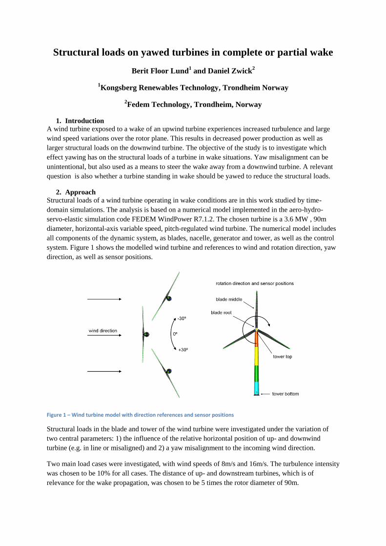
system. Figure 1 shows the modelled wind turbine and references to wind and rotation direction, yaw
direction, as well as sensor positions.
Figure 1 – Wind turbine model with direction references and sensor positions
Structural loads in the blade and tower of the wind turbine were investigated under the variation of
two central parameters: 1) the influence of the relative horizontal position of up- and downwind
turbine (e.g. in line or misaligned) and 2) a yaw misalignment to the incoming wind direction.
Two main load cases were investigated, with wind speeds of 8m/s and 16m/s. The turbulence intensity
was chosen to be 10% for all cases. The distance of up- and downstream turbines, which is of
relevance for the wake propagation, was chosen to be 5 times the rotor diameter of 90m.

The wind field has been generated using TurbSim. For the free flow situation, a Kaimal spectrum has
been used. The wake situation has been simulated reducing the average wind speed according using
the Larsen wake model. In addition, the turbulence intensity inside the wake has been altered both in
the flow direction as well as radially. For this correction, a number of experimental studies have been
used as a basis. Based on adaptation to these studies, the Garrad-Hassan model [1] was chosen for the
average added turbulence the wake in the flow direction.
The turbulence intensity in the wake also varies both radially and with the shear and partially with the
rotational direction of the turbine as shown in many experimental studies ,[3] , [4] [8] ,[10] ,[11] .
Figure 1 shows the resulting average wind speed (top row), standard deviation in wind speed (middle
row) and resulting turbulence intensity in the bottom row, for different locations of the wake on the
turbine area of the turbine standing in wake.
Figure 2 The wind average wind speed and turbulence field in a turbine area with different wake center locations. Free wind speed at hub height is 8m/s, ambient turbulence intensity is 10%, and x/D=5.
Wake meandering effects have not been included in the correction scheme, as opposed to e.g. [14]
and [15] . Inclusion of wake meandering would also require that a yaw control strategy would have to
be considered as meandering effects may cause significant yaw control actions in an real turbine. Here,
the yaw is considered constant during the simulation time, as is the wake center location in each
simulation case.
3. Main results The motivation of this work is to improve knowledge about the load consequences for yawed turbines
in complete or partial wake. The analysis is based on a study to investigate operation states, which are
beneficial in terms of reduced loads, and to identify critical load conditions. Results are referred to an
upwind turbine exposed to turbulent wind only, i.e. no wake.
Generator power can be considered as a measurement of the incoming wind over the rotor plane.
Wake effects, as well as yaw influences can directly be seen by analyzing the produced power. Figure
3 shows the generated power and pitch angle for 8, 11 and 16 m/s. The turbine manages to maintain a
high production at 16 m/s also in a yawed situation by pitching less.

Figure 3 Generated power vs yaw angle for windspeeds 16m/s, 11 m/s, 8 m/s.
The edgewise and flapwise bending moments on the blades as a function of yaw angle are shown in
Figure 4. It can be seen that the edgewise bending moments at the blade root and blade middle are
slightly larger for when yawing in a positive direction instead of a negative direction. The flapwise
bending moments are more symmetrical.
Figure 4 Edgewise and flapwise bending moments at 16m/s, 11 m/s, 8 m/s.
In the following, the results are for a turbine which is exposed to a wake flow field. Only the cases
8m/s and 16 m/s are included.
Figure 5 shows the reduction of produced power as a function of yaw angle (vertically) and in
addition wake displacement (horizontally). A reduction value of 0.0 (dark blue) means no reduction of
power compared to the free flow case, 0.6 means a 60% reduction. A value along the horizontal axis
of 0m indicates that the center of the wake wind field is at the center of the turbine in wake.
Increasing values in wake displacement lead to an unsymmetrical wake loading on the turbine, until
the displacement is large enough that the wake wind field is not acting on the turbine any more. This

case can be compared to results of a turbine in turbulent wind only, as in Figure 3, which is shown by
a wake displacement of ‘inf’ in the figure. In contrast to the expected power reduction, both for low
and high wind speeds, the standard deviation for 8m/s shows a set of parameters with increased values
for about 75m wake displacement and 0 degrees yaw.
Figure 5 Generator power and pitch angle
This result of a certain wake position with unexpected characteristic was further investigated by
analyzing loads at the blade root of the rotor, as well as at the tower bottom of the wind turbine.
Results are shown in Figure 6 and Figure 7 and are normalized to the reference case of infinity wake
displacement and 0 degrees yaw angle.
At the blade root, a symmetrical behavior of the mean loads in terms of yaw angle variation can be
observed. However, the standard deviation of both edge- and flapwise bending moment shows again a
set of values which are not symmetrical. When comparing the different results for edge- and flapwise
bending moments, as well as the different wind speeds, no consistent trend can be seen for a load
reduction. In some cases, a positive yaw angle leads to reduced loads, while other cases show the
opposite behavior. However, a critical wake displacement can again be extracted from the analysis,
which lies around 50-75m.

Figure 6 Edge- and flapwise bending moment at the blade root
Bending moments in the tower bottom in side-to-side direction are strongly influenced by the yaw
angle, which will lead to a loading in one or the other direction of the tower axis facing the wind. The
fore-aft bending moment is symmetrical to yaw angle variations, and shows a reduction for a turbine
in wake for low wind speeds. However, such loading conditions increase the standard deviation of the
fore-aft bending moment.
Figure 7 Side-to side and fore-aft bending moment at the tower bottom
4. Conclusion
The analysis of a turbine in wake shows that both the relative position of the wake center, as well as
the yaw angle of the turbine has directly influence on the structural loads. This is especially noticeable
for bending moments of the blades. As the rotor has a certain rotation direction, yaw angles in positive
or negative direction can have different influences on the loads. For high wind speeds, edgewise
bending moments can increase by 50% if yawed in positive direction; for flapwise bending moments,
the opposite behavior was found.
The relative horizontal position of the wake center on the turbine in wake, which was identified by the
wake displacement in this study, is an important parameter for the structural loading. Mean values for
bending moments at blade and tower sensors can mostly be reduced for an increasing overlap of wake
field and rotor for low wind speeds. For high wind speeds, however, the same conditions lead to
increasing structural loads.
5. Learning objectives The simulation study shows the structural loads on yawed turbines operating in a free flow or in a
wake. The study shows among other things that the loads on a yawed turbine are not symmetrical with
the yaw direction. The analysis has been made both as a function of yaw angle as well as wake center
placement on the rotor area.
References
[1] Burton, T. and N. Jenkins, D. Sharpe, E. Bossyani, Wind Energy Handbook 2nd ed., Wiley, 2011.
[2] Vermeer L.J, J.N. Sørensen, A. Crespo, Wind turbine wake aerodynamics, Progress in Aerospace Sciences (2003) 467-510.
[3] Mikkelsen, Kristine, Effect of free stream turbulence on wind turbine performance, NTNU Master thesis June 2013.
[4] Yu-Ting Wu and Fernando Porté-Angel, Atmospheric Turbulence Effects on Wind-Turbine Wakes: An LES Study, Energies (2012), 5, 5340-5362; doi:10.3390/en5125340
[5] K. Rados, G. Larsen, R. Barthelmie, W. Schlez, B. Lange, G. Schepers, T. Hegberg and M. Magnisson, Comparison of Wake Models with Data for Offshore Windfarms, Wind Engineering Vol. 25, No. 5, (2001), pp 271-280
[6] A. Stidworthy, D. Carruthers, J. Hunt, CERC activities during the TOPFARM project: Wind turbine modelling using ADMS, Cambridge Environmental Research Consultants (2011)
[7] Welsh, Andrew, Low Turbulence Wind Tunnel Design and Wind Turbine Wake Characterization (2013). Theses and Dissertations. Paper 180.
[8] Jimenez, Angel, A. Crespo, E. Migoya, J. Garcia and F. Manual, Large Eddy Simulation of a Wind Turbine Wake, Technical University of Madrid, Madrid.
[9] T. Hahm and S. Wußow, Turbulent Wakes in Wind Farm Configuration, TÜV NORD SysTec GmbH & Co. KG
[10] J. Murata, T. Maeda and Y. Kamada, Wind Field and Wind turbine Load in Wake for Various Ambient Turbulence Intensities, National Institute of Advanced Industrial Science and Technology (2012)

[11] R. Gómez-Elvira, A. Crespo, E. Migoya, F. Manuel, J. Hernández, Anisotropy of turbulence in wind turbine wakes, Journal of Wind Engineering and Industrial Aerodynamics 93 (2005) 797-814
[12] J. M. Prospathopoulos, E. S. Politis, K. G. Rados and P. K. Chaviaropolulos, Evaluation of the effects of turbulence model enhancements on wind turbine wake predictions, Wind Energy (2011) 14:285-300, doi: 10.1002/we.419
[13] PE. Réthoré, Wind turbine wake in atmospheric turbulence, PhD thesis, Aalborg University 2009
[14] S. T. Frandsen, Turbulence and turbulence generated structural loading in wind turbine clusters, Risø National Laboratory, Risø-R-1188(EN), Denmark 2007
[15] K Thomsen, H Aa Madsen, G C Larsen, T J Larsen Comparison of methods for load simulation for wind turbines operating in wake, 2007