Structural Effects of Reinforcement Corrosion in Concrete...
51
THESIS FOR THE DEGREE OF DOCTOR OF PHILOSOPHY Structural Effects of Reinforcement Corrosion in Concrete Structures MOHAMMAD TAHERSHAMSI Department of Civil and Environmental Engineering Division of Structural Engineering Concrete Structures CHALMERS UNIVERSITY OF TECHNOLOGY Gothenburg, Sweden 2016
Transcript of Structural Effects of Reinforcement Corrosion in Concrete...
THESIS FOR THE DEGREE OF DOCTOR OF PHILOSOPHY
Structural Effects of Reinforcement Corrosion in Concrete Structures
MOHAMMAD TAHERSHAMSI
Department of Civil and Environmental Engineering Division of Structural Engineering
Concrete Structures CHALMERS UNIVERSITY OF TECHNOLOGY
Gothenburg, Sweden 2016
Structural Effects of Reinforcement Corrosion in Concrete Structures MOHAMMAD TAHERSHAMSI MOHAMMAD TAHERSHAMSI ISBN 978-91-7385-552-5 © MOHAMMAD TAHERSHAMSI, 2016
Doktorsavhandlingar vid Chalmers tekniska högskola Ny serie Nr. 4108 ISBN no. 978-91-7597-427-9 ISSN no. 0346-718X Department of Civil and Environmental Engineering Division of Structural Engineering, Concrete Structures Chalmers University of Technology SE-412 96 Gothenburg, Sweden Telephone: + 46 (0)31-772 1000 Cover: The cover picture shows results from test and numerical analysis of an indirectly supported four-point bending test on a Medium damaged specimen. Three dimensional optical scanned and a photo of a part of a corroded rebar (M10) before and after tensile testing, respectively, indicating the existence of hidden corrosion pits. Chalmers Repro Service / Department of Civil and Environmental Engineering Gothenburg, Sweden, 2016
I
Structural Effects of Reinforcement Corrosion in Concrete Structures MOHAMMAD TAHERSHAMSI Department of Civil and Environmental Engineering Division of Structural Engineering, Concrete Structures Chalmers University of Technology
ABSTRACT Reinforcement corrosion is a common cause of deterioration in reinforced concrete. The corrosion mechanism involved and the consequent structural behaviour of deteriorated reinforced concrete members have been studied by several researchers. Nevertheless, the knowledge obtained is primarily based on experimental investigations of artificially corroded specimens whereas natural corrosion may affect structural behaviour differently. This thesis aims to deepen the understanding of the structural effects of natural corrosion deterioration with a focus on the remaining anchorage capacity between deformed bars and concrete, as well as the investigation of possible links between visual inspection data and structural damage. Tests on the anchorage capacity of naturally corroded reinforcement were carried out. The specimens were taken from the concrete edge beams of a 32-year old bridge that had been exposed to the outdoor environment. The tests were carried out using an indirectly supported four-point bending test. The overall structural behaviour of the specimens was examined through measurements of loads, vertical deflections and end-slip of the tensile rebars. The failure mode consisted of a splitting-induced pull-out failure in all tests. It was observed that the specimens with cracking and cover spalling had an average of 6 and 9 %, respectively, lower load-carrying capacity compared with the un-cracked ones. Two methods were used to quantify the corrosion level: gravimetric measurements and advanced 3D optical scanning. The correlations between the measured corrosion levels, splitting crack widths and the anchorage capacity of the corroded specimens were investigated, and the results were compared with artificial corrosion tests from literature. For the same crack widths, the specimens in this study had much less corrosion level and slightly higher bond capacity compared to other studies found in literature with artificially induced corrosion. Furthermore, it was also investigated how well analyses on different levels can describe the structural behaviour - from advanced modelling to a simplified approach that can be used in practice. In the most advanced approach, three-dimensional non-linear finite element (3D NLFE) analyses employing previously developed bond and corrosion models were carried out. This approach yielded results that were most consistent with the experimental observations; however, the analyses were computationally expensive. In the most simplified approach, a constant bond stress was assumed together with the available anchorage length measured, which underestimated the capacities. Thus, the simplified method applied was the most efficient analysis with results on the safe side. Ultimately, this study contributes to the knowledge on how the structural effects of reinforcement corrosion in existing structures can be assessed. The results indicate that using the available knowledge of artificial corrosion to formulate a damage indicator in the form of crack widths would yield estimations of the structural capacity on the safe side. The present study was based on a limited amount of experiments. Thus, more experiments on real structures are needed. Keywords: Bond properties, anchorage, structural behaviour, natural corrosion, reinforced concrete structures, experiments, load-carrying capacity, pitting, damage assessment, inspection, 3D optical scanning, FE analysis, modelling.
II
Korrosionsskadade betongkonstruktioners mekaniska verkningssätt MOHAMMAD TAHERSHAMSI Institutionen för bygg- och miljöteknik Konstruktionsteknik, Betongbyggnad Chalmers tekniska högskola
SAMMANFATTNING Armeringskorrosion är en vanlig orsak till nedbrytning av armerade betongkonstruktioner. Korrosionsmekanismen och det mekaniska verkningssättet hos korrosionsskadade konstruktionsdelar har undersökts av flera forskare. Rådande kunskapsläge är främst baserat på experiment med konstgjorda korrosionsangrepp, men naturlig korrosion kan leda till ett annat verkningssätt. Detta arbete syftar till att fördjupa förståelsen av det mekaniska beteendet hos naturligt korrosionsskadade betongkonstruktioner. Främsta fokus ligger på bestämning av återstående förankringskapacitet mellan skadade armeringsjärn och betong samt på att undersöka möjliga samband mellan visuell besiktning och konstruktionsteknisk skada. Förankringskapaciteten hos naturligt korroderade armeringsstänger provades. Provkropparna togs från kantbalkarna från en 32 år gammal bro och har således varit utsatta för en utomhusmiljö. De provades i fyr-punkts böjning med upphängda ändstöd. Det generella verkningssättet hos provkropparna undersöktes genom att last, nedböjning samt dragarmeringens ändglidning mättes. Brottmoden bestod av spjälkinducerat utdragsbrott i alla försöken. Provkroppar med uppspruckna respektive avspjälkade täckskikt uppvisade 6 respektive 9 % lägre bärförmåga än de med ospruckna täckskikt. Två metoder användes för att kvantifiera korrosionsgraden, gravimetri och avancerad optisk 3D-skanning. Korrelationen mellan uppmätta korrosionsnivåer, spjälksprickbredd samt förankringskapacitet undersöktes och jämfördes med försöksresultat från artificiellt korroderade provkroppar i litteraturen. För samma spjälksprickbredd hade provkropparna i denna studie mycket mindre korrosionsnivå och något större vidhäftningskapacitet jämfört med andra studier i litteraturen med artificiell korrosion. Vidare undersöktes hur väl analyser på olika nivåer kan beskriva det mekaniska verkningssättet – från avancerad modellering till en förenklad ingenjörsmässig metod. I den mest avancerade ansatsen användes tredimensionell icke-linjär finit elementanalys där tidigare utvecklade beräkningsmodeller användes för korrosion- och vidhäftningsbeteendet. Detta tillvägagångssätt gav de resultat som stämde bäst överens med experimentella observationer, men analyserna var beräkningsmässigt krävande. I den mest förenklade ansatsen antogs en konstant vidhäftningsspänning över den uppmätta förankringslängden, vilket underskattade kapaciteten. Denna enkla metod var den mest tidseffektiva och gav resultat på säker sida. Detta arbete fördjupar kunskapen om hur det mekaniska verkningssättet hos befintliga betongkonstruktioner med korroderad armering kan bedömas. Resultaten indikerar att en skadeindikator baserad på sprickbredd skulle leda till uppskattningar av bärförmågan som är på säker sida, om resultat från försök med artificiell korrosion används för att kalibrera modeller. Den utförda studien baserades på ett begränsat antal experiment. Därför krävs fler försök med naturligt nedbrutna konstruktioner. Nyckelord: Vidhäftning, förankring, mekaniskt verkningssätt, naturlig korrosion, armerade betongkonstruktioner, experiment, bärförmåga, punktkorrosion, skadebedömning, inspektion, optisk 3D skanning, FE analys, modellering.

III
“Be happy for this moment. This moment is your life.” Khayyám (1048-1131)
IV
Contents ABSTRACT I
SAMMANFATTNING II
PREFACE VII
LIST OF PUBLICATIONS IX
1 INTRODUCTION 1
1.1 Background 1
1.2 Aim and objectives 2
1.3 Method and scientific approach 2
1.4 Scope and limitations 3
1.5 Research significance 3
1.6 Outline of thesis 4
2 LOAD-CARRYING CAPACITY OF CORRODED RC STRUCTURES 5
2.1 Mechanism of corrosion damage 5
2.2 Mechanical properties of corroded steel bars 6
2.3 Bond between corroded reinforcement and concrete 6
2.4 Mechanical behaviour of corroded RC structures 8
3 EXPERIMENTS ON SPECIMENS FROM STALLBACKA BRIDGE 10
3.1 Test specimens and test set-up design 10
3.2 Anchorage capacity 12
3.3 Links between crack width, corrosion level and bond 14
3.4 Comparison to other experimental work 18
4 ANALYSIS OF SPECIMENS FROM STALLBACKA BRIDGE 24
4.1 Overview of analysis levels 24
4.1.1 FE analysis including bond and corrosion models (Level IV) 24
4.1.2 FE analysis including 1D bond-slip model (Level III) 25
4.1.3 Simplified approach using 1D bond slip model (Level II) 27
4.1.4 Simple approach for engineering practice (Level I) 27
4.2 Results 28
5 CONCLUSIONS 30
5.1 General conclusions 30
V
5.2 Suggestions for future research 32
6 REFERENCES 33
APPENDED PAPERS
PAPER I: Tests on Anchorage of Naturally Corroded Reinforcement in Concrete I-0
PAPER II: Anchorage of Naturally Corroded Bars in RC Structures II-0
PAPER III: Investigating Correlations between Crack Width, Corrosion Level and Anchorage Capacity III-0
PAPER IV: Four Levels to Assess Anchorage Capacity of Corroded Reinforcement in Concrete IV-0

VI
VII
Preface This doctoral thesis aims at providing new insights into the influence of corrosion deterioration on structural behaviour of naturally corroded reinforced concrete structures through experimental and numerical investigations. The project was carried out at the Division of Structural Engineering, Department of Civil and Environmental Engineering, Chalmers University of Technology from October 2011 until August 2016. The author wishes to express his gratitude to the Swedish Transport Administration, Trafikverket, for financing this project.
I would like to express my sincere gratitude to my main supervisor and examiner, Professor Karin Lundgren, for her tremendous support, encouragement and excellent guidance throughout this research project. Prof. Lundgren has been a constant source of inspiration to me. She is not only a great researcher with genuine research ideas but also a very good leader. She cares deeply about all her students. She made me believe in myself time upon time when I was stuck on research and feeling discouraged. I am thankful to my co-supervisor, Assoc. Prof. Kamyab Zandi, who offered both invaluable technical and personal guidance along the way to complete my work. I am thankful to my good friend and second co-supervisor during the final year of my Ph.D. studies, Ignasi Fernandez, Post doc., for all his help and support. Ignasi’s brilliant research ideas and inputs truly enriched my research work. My grateful thanks also go to Assoc. Prof. Mario Plos for being my co-supervisor during the first three years of my doctoral studies and Jonas Magnusson, Ph.D. at NCC, for taking the time out of his busy schedule to participate in both the Reference group and several project meetings to share his expertise. I would also like to thank other members of the Reference group, including Robert Ronnebrant, Björn Engström, Kent Gylltoft, Peter Utgenannt and Poul Linneberg, for their interest in the project and for their excellent discussions and comments. My grateful thanks are also extended to Master’s students Fredrik Berg, David Johansson, Eyrun Gestsdottir and Tomas Gudmundsson for their diligent participation within this project. I would like to thank my true friend, Mohsen Heshmati, for his friendship, guidance and help. I wish him grand success and a bright future in all his endeavors. I thank Mattias Blomfors for all interesting discussions we had regarding our projects and also his help with the Swedish abstract of this thesis. Special thanks goes to Gunilla Ramell for her language editing on this thesis and appended journal articles.
This study has included a large amount of experimental work. Thus, I would like to thank laboratory engineers Lars Wahlström and Sebastian Almfeldt for their excellent work during the execution of all tests. I would like to thank all my friends and colleagues at the Department of Civil and Environmental Engineering for their help, support and constructive discussions.
My sincerest gratitude goes out to my dearest family, my lovely parents and siblings, for their heartfelt devotion, support and encouragement during all my years of study. Last but certainly not least, I send my love and gratitude to my wonderful fiancé, Johanna, for her endless love, support and understanding throughout these past years.
It is wonderful having a memory to look back on smilingly knowing that the best is yet to come.
Gothenburg, 2016
Mohammad Tahershamsi

VIII
IX
LIST OF PUBLICATIONS
This thesis is based on the work presented in the following papers:
Paper I Lundgren K., Tahershamsi M., Zandi K. and Plos M. (2015): Tests on Anchorage of Naturally Corroded Reinforcement in Concrete. Published in Materials and Structures, 48(7), p. 2009-2022
Paper II Tahershamsi M., Zandi K., Lundgren K. and Plos M. (2014): Anchorage of Naturally Corroded Bars in RC Structures. Published in Magazine of Concrete Research, 66(14), p. 729-744
Paper III Tahershamsi M., Fernandez I., Lundgren K. and Zandi K. (2016): Investigating Correlations between Crack Width, Corrosion Level and Anchorage Capacity. Submitted for publication in Structure and Infrastructure Engineering.
Paper IV Tahershamsi M., Fernandez I., Zandi K. and Lundgren K. (2016): Four Levels to Assess Anchorage Capacity of Corroded Reinforcement in Concrete. Submitted for publication in Engineering Structures.
AUTHOR’S CONTRIBUTIONS TO JOINTLY PUBLISHED PAPERS
The contributions of the author of this doctoral thesis to the appended papers are described here:
I. Shared responsibility for the planning of the experiments. Responsible for theexecution of a major part of the experiments. Contributed to writing the paper.
II. Responsible for the writing and for the major part of the planning of the paper.Responsible for planning and execution of the experiments.
III. Responsible for the planning and execution of the measurements anddocumentations. Conducted literature survey as well as comparing results withthe available data from the literature. Main responsibility in planning andwriting of the paper except Section 3 where the contribution consisted ofdiscussions and cooperation during the work and commenting the text.
IV. Conducted numerical modelling at Level IV and hand calculations at Level Ianalysis, as well as evaluation of the results. Conducted the literature survey.Main responsibility in planning and writing of the paper except Sections 3.2,3.3 and 4.2 where the contribution consisted of discussions and cooperationduring the work and commenting the text.
X
ADDITIONAL PUBLICATIONS BY THE AUTHOR
Licentiate Thesis Tahershamsi M. (2013): Anchorage of Corroded Reinforcement in Existing Concrete Structures, Experimental Study. Degree for Licentiate of Engineering, Licentiate Thesis No. 2013:10, Civil and Environmental Engineering, Chalmers University of Technology, pp. 19.
Conference Papers Tahershamsi M., Zandi Hanjari K., Lundgren K. and Plos M. (2012): Anchorage capacity of naturally corroded reinforced concrete beams. Proceeding of the fib Symposium, Concrete Structures for Sustainable Community, 11-14 June 2012, KTH Royal Institute of Technology, Stockholm, Sweden, p. 323-326.
Tahershamsi M., Zandi Hanjari K., Lundgren K. and Plos M. (2012): Anchorage in naturally corroded specimens taken from existing structures. Proceeding of the Fourth International Symposium on Bond in Concrete 2012: Bond, Anchorage, Detailing, Brescia, Italy, 17-20 June 2012, Editors: John w. Cairns, Giovanni Metelli, Giovanni A. Plizzari Vol. 1, General Aspects of Bond (2012), p. 345-349.
Tahershamsi M., Zandi Hanjari K., Lundgren K. and Plos M. (2013): Assessment of anchorage capacity of naturally corroded reinforcement. International Association for Bridge and Structural Engineering, IABSE Conference, Assessment, Upgrading and Refurbishment of Infrastructures, 06-08 May 2013, Rotterdam, The Netherlands, p. 556-557.
Tahershamsi M., Zandi Hanjari K., Lundgren K. and Plos M. (2014): Assessment of structural performance in naturally corroded reinforced concrete elements. Structural Faults and Repair 2014, 15th International Conference & Exhibition: Concrete, Materials and Conservation at Imperial College, University of London, 08-10 July 2014, London, UK.
Fernandez I., Tahershamsi M., Lundgren K. and Zandi K. (2014): 1D and 3D analysis of anchorage in naturally corroded specimens. Proceedings of the 10th fib International PhD Symposium in Civil Engineering, Université Laval 21-23 July 2014, Québec, Canada, p. 547-552.
Lundgren K., Plos M., Tahershamsi M., and Zandi K. (2015). 3D Modelling of the bond behavior of naturally corroded reinforced concrete. Nordic Concrete Research, 2(53), Oslo, Norway, p. 35–38.
Popular Scientific Papers Lundgren K., Plos M., Zandi Hanjari K. and Tahershamsi M. (2012): Är förankringskapaciteten tillräcklig i broar med rostande armering? Bygg & Teknik (0281-658X). Vol. 104 (2012), 7, p. 17-19.

CHALMERS, Civil and Environmental Engineering
1
1 Introduction
1.1 Background In recent years, demands on extending the service life and increased traffic loads have heightened the interest in the durability and structural assessment of existing infrastructures, in particular owing to economic considerations. Meanwhile, ageing and deterioration due to aggressive environment have been occurring in many existing reinforced concrete (RC) structures, e.g. bridges, parking garages and off-shore structures. The deterioration may affect both serviceability and ultimate load-carrying capacity. Consequently, understanding the actual behaviour of an impaired structure and a realistic estimation of its remaining service life are of great importance to responsible authorities, stakeholders, engineers and researchers.
The corrosion of embedded reinforcement in concrete is considered to be one of the main causes of the deterioration of many existing RC structures; see Almusallam et al. (1996); Azad et al. (2007); Bertolini (2008); Cabrera (1996); Lundgren (2007) and Sistonen et al. (2008). Corrosion causes high costs in developed countries; as an example, the average annual cost to repair and replace conventional reinforced and prestressed concrete highway bridges specifically owing to corrosion damage was already fifteen years ago in the US more than $ 6.3 billion; see Koch et al. (2002) and Yunovich et al. (2001). Corrosion may affect the structural performance and integrity of reinforced concrete components to a considerable degree over the long run, CEB-fib (2000). The corrosion of steel bars embedded in concrete may lead to several undesirable consequences, such as potentially severe damage resulting in the loss of a cross-sectional area of steel, which would reduce both the capacity and ductility of the reinforcement; see Almusallam (2001); Du et al. (2005a) and Fernandez et al. (2015). Furthermore, by occupying a higher volume than the original steel, the corrosion products affect the surrounding concrete, thereby increasing the mechanical pressure around the reinforcement. Crack propagation and cover delamination are the two most common physical signs of this phenomenon according to Al-Sulaimani et al. (1990); Dang et al. (2013); Sæther (2010) and Val et al. (1998). The volume expansion of rust not only causes splitting stresses but also affects steel-concrete bond properties, for an overview see Al-Sulaimani et al. (1990); Lundgren (2007) and Sæther (2010). These effects must be specifically taken into consideration in structural assessments when corrosion takes place in anchorage zones; see Imbsen et al. (1987).
Over the past few decades, many research studies have been conducted focusing on tests of damaged reinforced concrete specimens subjected to artificial corrosion attack. The loss of stiffness during the service life, see Cairns et al. (2005), and the decrease of load-carrying capacity and ductility in the ultimate limit state, see Val et al. (2009); Zandi Hanjari et al. (2011); Azad (2007); Cairns et al. (1999); Dang et al. (2014); Fernandez et al. (2016); Law et al. (2008); Sæther (2011); Zandi Hanjari (2010) and Zhu et al. (2015), were the main findings of these studies. Saifullah et al. (1994) showed that the current density applied to accelerated corrosion tests may notably influence bond strength. The comparisons of test results with low and high corrosion rates showed deviant behaviour of the local bond, see Sæther (2010), differences attributed to the chemistry of corrosion products, their ability to escape through cracks or penetrate the
CHALMERS, Civil and Environmental Engineering
2
cement matrix, as well as concrete creep CEB-fib (2000). While much effort has been devoted to testing artificially corroded reinforced concrete, relatively little attention has been devoted to the problem of assessing the residual strength of corroded structures in natural environments. Accordingly, there was a strong need for experiments involving naturally corroded specimens in order to gain an understanding of the true behaviour of corroded structures, as well as valuing the validity of different assessment methods developed and calibrated based upon the test results of accelerated-corrosion tests.
Most of the above-mentioned research studies have been mainly focusing on the relationship between the degree of corrosion of steel reinforcement bars and the load-carrying capacity of corresponding RC elements. Several empirical, analytical and numerical models have been developed to correlate corrosion level to load-carrying capacity, e.g. Coronelli (2002); Wang et al. (2004); Berra et al. (2003); Lee et al. (2002); Bhargava et al. (2008); Lundgren (2005); Biondini et al. (2014). However, since corrosion levels cannot be easily measured in existing structures, these models do not yet have any direct practical application. Given the fact that cracking, as the first sign of deterioration in RC structures, is mostly detected through visual inspection, simplified models are needed to correlate cracking to structural strength. A few studies have investigated the correlation between corrosion attack and splitting crack opening on artificially corroded specimens; see Andrade et al. (2016) and Yu et al. (2015). In this study, it was of interest to focus on this issue by using samples of naturally corroded steel reinforcement bars in order to extend existing knowledge.
1.2 Aim and objectives The major aim of this study was to increase the knowledge of the bond and anchorage behaviour in naturally corroded reinforced concrete structures, as well as investigating the possible links between visual inspection data and structural damage. More specifically, the aim was to study the bond behaviour of naturally corroded ribbed bars in anchorage regions both experimentally and numerically to assess the anchorage capacity of corroded reinforcement in reinforced concrete members. Within this overall aim of the study, there are some specific objectives which relate to the different stages of the research project:
• Testing and compiling data of naturally corroded reinforced concrete specimens to assess bond behaviour and anchorage capacity
• Investigating different methods to determine the corrosion level of corroded reinforcement bars
• Investigating possible correlations between measured crack width, corrosion level and anchorage capacity
• Comparing naturally corroded test results with available artificial corrosion tests • Comparing different levels of available analysis methods with each other and
with the tests of naturally corroded beams in order to assess the structural behaviour of corroded structures
1.3 Method and scientific approach The scientific approach of this study has been primarily based on experiments and corresponding observations. Two series of experiments have been carried out to study
CHALMERS, Civil and Environmental Engineering
3
the effect of natural corrosion on the remaining load-carrying capacity of damaged concrete structures. The edge beams of a composite bridge deck were chosen as test specimens. The experiments were conducted by means of an indirectly supported four-point bending test set-up specifically designed to enable the study of anchorage behaviour. Corrosion levels of the reinforcement bars were measured using two methods, gravimetric weight loss and 3D scanning. The visible damages on specimens, such as crack width and spalling, were thoroughly documented before tests. Measured crack widths, corrosion levels and capacities were correlated to each other accordingly. A literature study was conducted to identify the effects of reinforcement corrosion in reinforced concrete members and to make comparisons between natural and artificial corrosion. Four different analysis methods were used to study the effects of natural corrosion on the structural behaviour of damaged RC beams.
1.4 Scope and limitations The limitations of the study can be summarised as follows:
• As the test specimens were taken from a real-life structure, it became impossible to be in total control of the design and construction of the test specimens.
• The anchorage of ribbed bars at the end regions alone was studied. • Due to the lack of information where the splices in the specimens were located,
their influence could not be considered when cutting the test specimens. However, the reinforcement bars were taken out of the beams after the structural testing and the location of splices were documented and used in the 3D FE analyses.
• To determine the corrosion level, the gravimetric measurement method was used to measure the remaining weight of the cleaned reinforcement bars from some specimens. Due to the lack of information regarding the original reference steel bars, the corrosion levels were calculated using the average weight of the non-corroded reinforcement bars from the reference specimens as reference.
• To determine the corrosion level by the optical 3D scanning method, an uncorroded zone of the bar had to be identified and its average cross-sectional area used as reference separately for each specimen.
• The presence of horizontal or subsurface corrosion could neither be measured nor detected by 3D optical measurement.
• Due to indications of freezing damage in concrete, the tensile strength used as input in the FE analyses was calculated from the compressive strength by a proposed equation for frost-damaged concrete. It should be mentioned that a few material tests of tensile strength were carried out on some concrete samples. However, they were not considered representative for all specimens.
1.5 Research significance The original contributions of this study are summarised as follows:
• Experiments of naturally corroded specimens from the field were carried out; more specifically, bond and anchorage behaviours of naturally corroded ribbed bars in two test series were studied.
CHALMERS, Civil and Environmental Engineering
4
• The results compiled of specimens taken from a bridge with reinforcement corroded in a natural environment are to the author’s knowledge rare if not unique.
• The anchorage capacities of the tested specimens exposed to a naturally corrosive environment were compared with selected artificially corroded test specimens from the literature. Correlations between crack width, corrosion level and anchorage capacity were investigated and compared to tests results in the literature.
• Different levels of analyses from 3D nonlinear finite element analyses to simple engineering approaches were compared to each other and to the tests of naturally corroded beams.
1.6 Outline of thesis The thesis consists of an introductory part and four appended papers. In Chapter 1, the aim, objectives and scope of the study together with a general description of its scientific methods and original contributions are provided. Chapter 2 presents a general background on the mechanisms of corrosion damage and the bond behaviour of corroded structures. In Chapter 3, the experimental work carried out in this thesis is briefly described; for more details, see Papers I, II and III. Chapter 4 deals with advanced and simplified methods to assess the remaining capacity of naturally corroded beams; for more details, see Paper IV. Conclusions and suggestions for future research are outlined in Chapter 5.
CHALMERS, Civil and Environmental Engineering
5
2 Load-carrying capacity of corroded RC structures
2.1 Mechanism of corrosion damage Many environmental factors can influence the durability of reinforced concrete. Corrosive agents, e.g. de-icing or seawater salts, are the most common causes of deterioration in RC structures. The reinforcement embedded in the alkaline environment is protected by a passive layer. The steel passivity can, however, be broken down by a loss of alkalinity due to chloride attack or carbonation of concrete; this phenomenon leads to an increased vulnerability of steel reinforcement to corrosion, Domone et al. (2010).
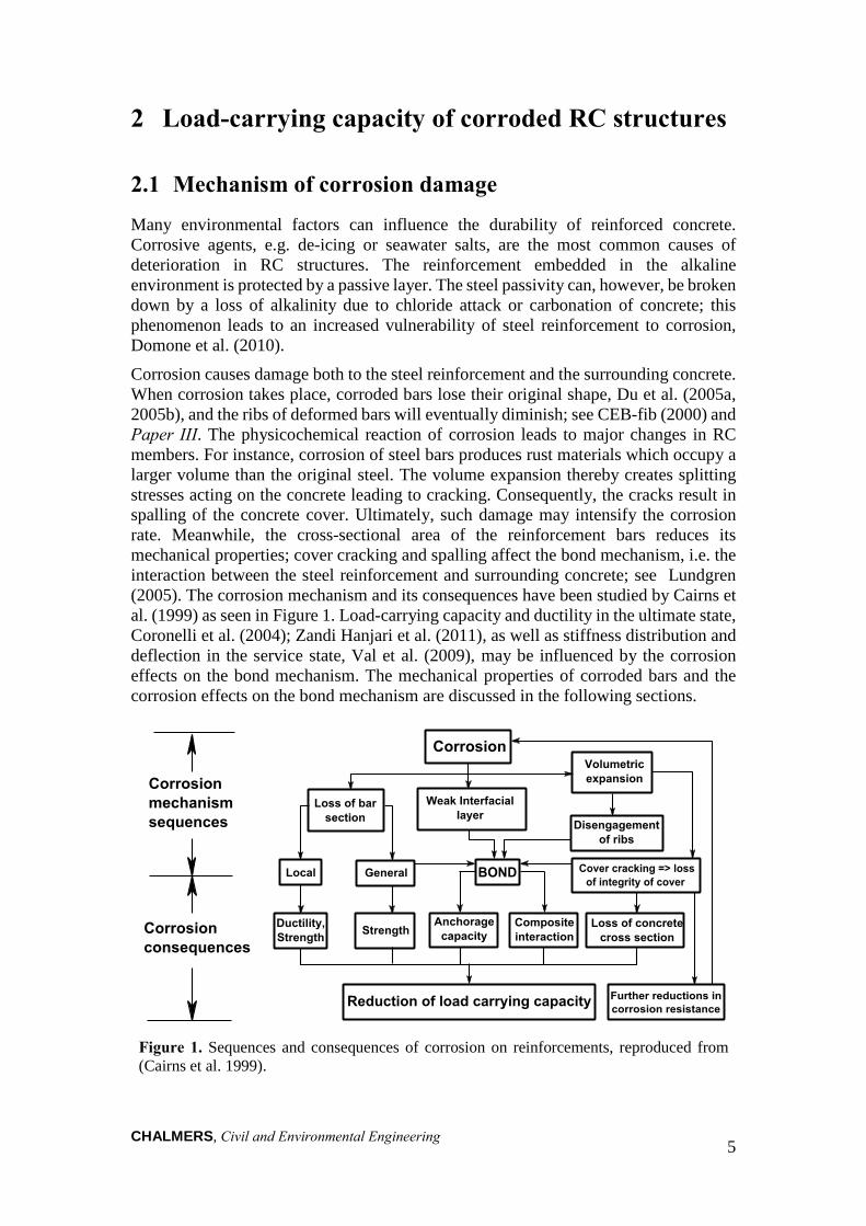
Corrosion causes damage both to the steel reinforcement and the surrounding concrete. When corrosion takes place, corroded bars lose their original shape, Du et al. (2005a, 2005b), and the ribs of deformed bars will eventually diminish; see CEB-fib (2000) and Paper III. The physicochemical reaction of corrosion leads to major changes in RC members. For instance, corrosion of steel bars produces rust materials which occupy a larger volume than the original steel. The volume expansion thereby creates splitting stresses acting on the concrete leading to cracking. Consequently, the cracks result in spalling of the concrete cover. Ultimately, such damage may intensify the corrosion rate. Meanwhile, the cross-sectional area of the reinforcement bars reduces its mechanical properties; cover cracking and spalling affect the bond mechanism, i.e. the interaction between the steel reinforcement and surrounding concrete; see Lundgren (2005). The corrosion mechanism and its consequences have been studied by Cairns et al. (1999) as seen in Figure 1. Load-carrying capacity and ductility in the ultimate state, Coronelli et al. (2004); Zandi Hanjari et al. (2011), as well as stiffness distribution and deflection in the service state, Val et al. (2009), may be influenced by the corrosion effects on the bond mechanism. The mechanical properties of corroded bars and the corrosion effects on the bond mechanism are discussed in the following sections.
Figure 1. Sequences and consequences of corrosion on reinforcements, reproduced from (Cairns et al. 1999).
CHALMERS, Civil and Environmental Engineering
6
2.2 Mechanical properties of corroded steel bars The effects of corrosion on the mechanical properties of reinforcement have been studied by many researchers, e.g. Apostolopoulos et al. (2007, 2008); Apostolopoulos (2007); Apostolopoulos et al. (2006); and Zhang et al. (2012). According to CEB-fib (2000), corrosion may be classified into two categories: general and local. General corrosion occurs when the corrosion is uniformly distributed along the reinforcement, so-called generalised corrosion, whereas localized corrosion forms local pits along the steel bar, named pitting corrosion. Generalized corrosion is commonly claimed to be caused by carbonation, whereas pitting corrosion is invariably associated with chloride contamination (CEB-fib 2000). Both pitting and generalised corrosion have important effects on the degradation of the mechanical properties of steel bars (Apostolopoulos et al. 2008).
In the case of pitting, the ultimate strain is severely reduced by corrosion. It is sufficient with only 10 % of non-uniform corrosion to reduce the ductility of bars embedded in the concrete to below the minimum requirement specified in design codes for use in high ductility situations (Du et al. 2005a). Furthermore, Almusallam (2001) concluded that the stress-strain characteristics of corroded reinforcements indicate a decrease in the ductility with an increase in the corrosion level. Other steel parameters, such as yielding and ultimate stresses, are significantly reduced by corrosion (Apostolopoulos et al. 2006; Du et al. 2005a, 2005b; Fernandez et al. 2015).
Different effects may occur due to the formation of the pits on a reinforcement bar subjected to tension; local bending on the pitted cross-section due to a displacement of the centre of gravity, as well as stress localization on the tip of the pit, may explain the important drop in the main mechanical properties of the steel bar (Fernandez et al. 2016). The formation of large and localized strains due to such phenomena is also an important consequence; since the length of corrosion pit is short, the average strain in the entire bar becomes lower than the strain at a local pit (Stewart et al. 2008), causing the corroded bars to fail at deformations much smaller than that of the original bar; thus, corrosion causes the reinforcement to behave in a brittle manner (Coronelli et al. 2004; Du et al. 2005a).
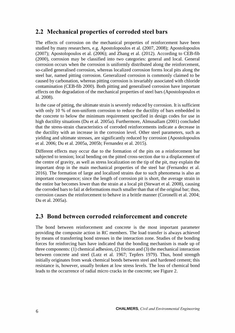
2.3 Bond between corroded reinforcement and concrete The bond between reinforcement and concrete is the most important parameter providing the composite action in RC members. The load transfer is always achieved by means of transferring bond stresses in the interaction zone. Studies of the bonding forces for reinforcing bars have indicated that the bonding mechanism is made up of three components: (1) chemical adhesion, (2) friction and (3) the mechanical interaction between concrete and steel (Lutz et al. 1967; Tepfers 1979). Thus, bond strength initially originates from weak chemical bonds between steel and hardened cement; this resistance is, however, usually broken at low stress levels. The loss of chemical bond leads to the occurrence of radial micro cracks in the concrete; see Figure 2.
CHALMERS, Civil and Environmental Engineering
7
Figure 2. Longitudinal and transverse cracks caused by bond stresses, as modified by Magnusson (2000) based on Vanderwalle (1992).
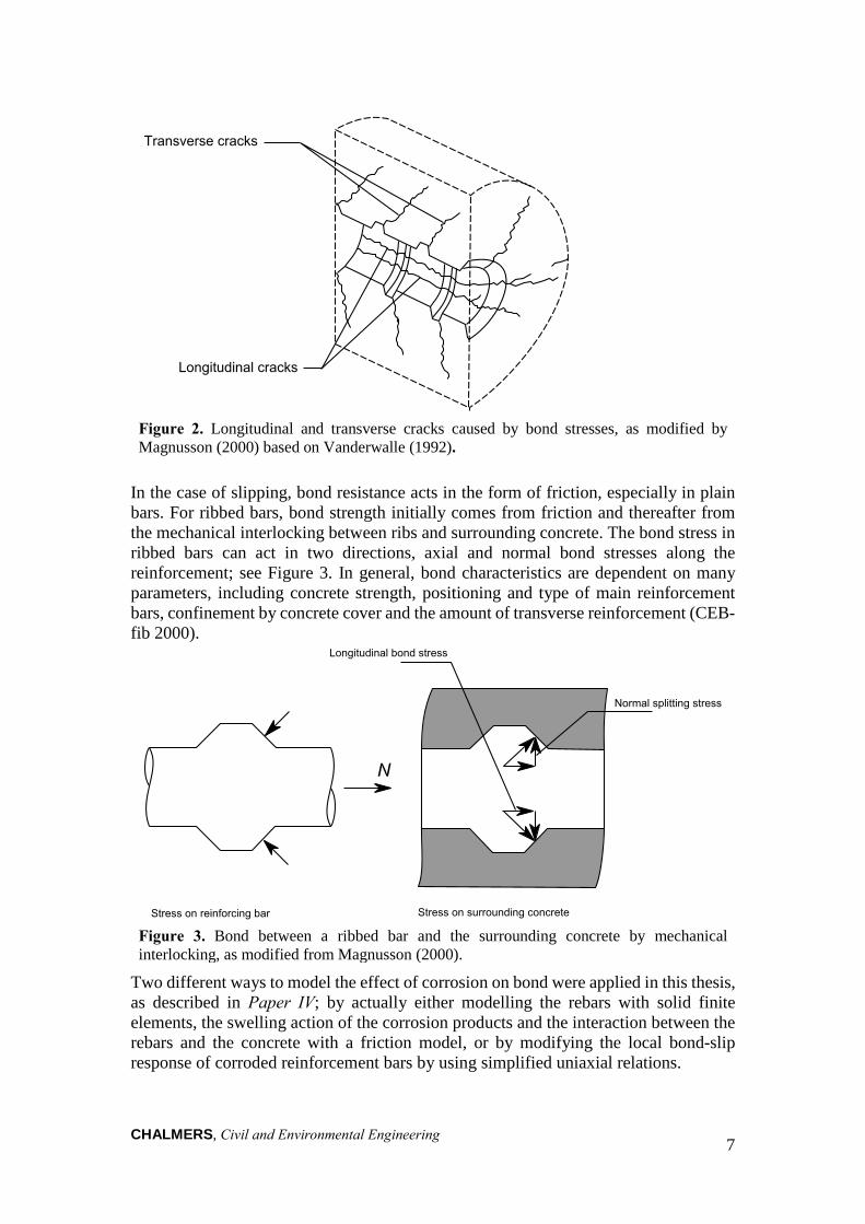
In the case of slipping, bond resistance acts in the form of friction, especially in plain bars. For ribbed bars, bond strength initially comes from friction and thereafter from the mechanical interlocking between ribs and surrounding concrete. The bond stress in ribbed bars can act in two directions, axial and normal bond stresses along the reinforcement; see Figure 3. In general, bond characteristics are dependent on many parameters, including concrete strength, positioning and type of main reinforcement bars, confinement by concrete cover and the amount of transverse reinforcement (CEB-fib 2000).
Figure 3. Bond between a ribbed bar and the surrounding concrete by mechanical interlocking, as modified from Magnusson (2000).
Two different ways to model the effect of corrosion on bond were applied in this thesis, as described in Paper IV; by actually either modelling the rebars with solid finite elements, the swelling action of the corrosion products and the interaction between the rebars and the concrete with a friction model, or by modifying the local bond-slip response of corroded reinforcement bars by using simplified uniaxial relations.
CHALMERS, Civil and Environmental Engineering 8
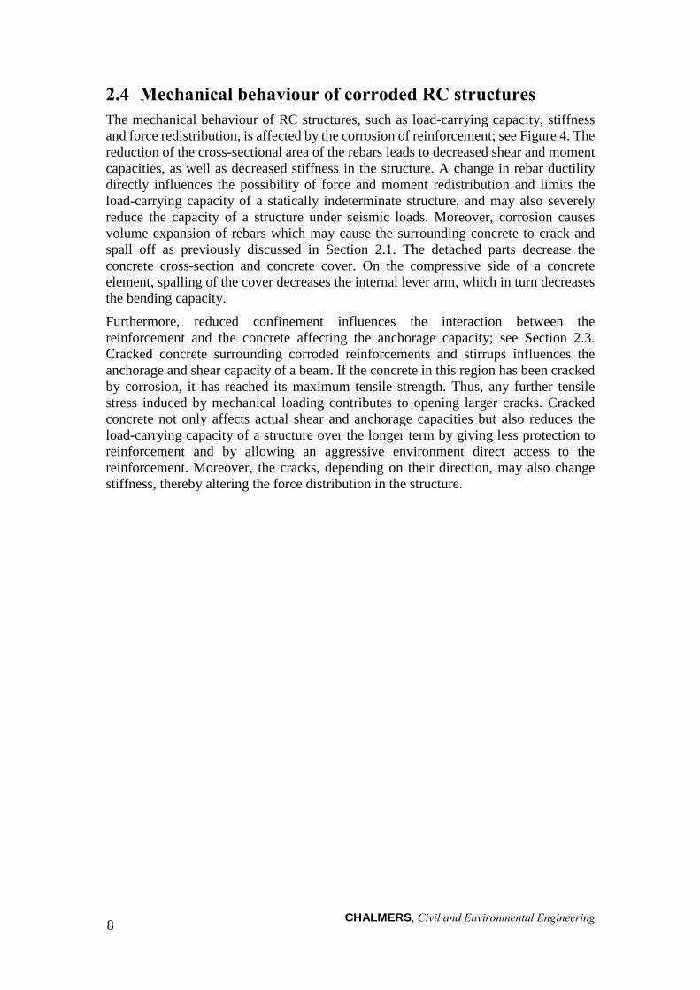
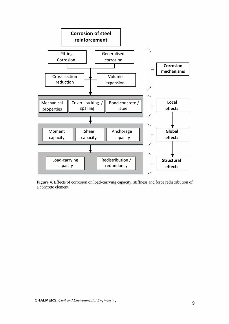
2.4 Mechanical behaviour of corroded RC structures The mechanical behaviour of RC structures, such as load-carrying capacity, stiffness and force redistribution, is affected by the corrosion of reinforcement; see Figure 4. The reduction of the cross-sectional area of the rebars leads to decreased shear and moment capacities, as well as decreased stiffness in the structure. A change in rebar ductility directly influences the possibility of force and moment redistribution and limits the load-carrying capacity of a statically indeterminate structure, and may also severely reduce the capacity of a structure under seismic loads. Moreover, corrosion causes volume expansion of rebars which may cause the surrounding concrete to crack and spall off as previously discussed in Section 2.1. The detached parts decrease the concrete cross-section and concrete cover. On the compressive side of a concrete element, spalling of the cover decreases the internal lever arm, which in turn decreases the bending capacity.
Furthermore, reduced confinement influences the interaction between the reinforcement and the concrete affecting the anchorage capacity; see Section 2.3. Cracked concrete surrounding corroded reinforcements and stirrups influences the anchorage and shear capacity of a beam. If the concrete in this region has been cracked by corrosion, it has reached its maximum tensile strength. Thus, any further tensile stress induced by mechanical loading contributes to opening larger cracks. Cracked concrete not only affects actual shear and anchorage capacities but also reduces the load-carrying capacity of a structure over the longer term by giving less protection to reinforcement and by allowing an aggressive environment direct access to the reinforcement. Moreover, the cracks, depending on their direction, may also change stiffness, thereby altering the force distribution in the structure.
CHALMERS, Civil and Environmental Engineering 9
Figure 4. Effects of corrosion on load-carrying capacity, stiffness and force redistribution of a concrete element.
Pitting
Corrosion
Generalised
corrosion
Mechanical
properties
Cover cracking / spalling
Bond concrete /steel
Local
effects
Structural
effects
Corrosion of steel reinforcement
Moment
capacity
Shear
capacity
Anchorage
capacity
Load-carrying capacity
Redistribution / redundancy
Global
effects
Cross section reduction
Volume
expansion
Corrosion mechanisms
CHALMERS, Civil and Environmental Engineering 10
3 Experiments on specimens from Stallbacka Bridge In this study, experiments were conducted to investigate the load-carrying capacity of existing naturally corroded specimens. The aim was to better understand the effects of natural corrosion on cracking and bond strength in the anchorage regions, as well as to investigate possible correlations between visual inspection data and structural damage. The structural behaviour of corrosion-induced damage in the form of corrosion-induced cracking and cover spalling were studied. The experiments were carried out in two test series:
• The first test series comprised eight specimens from the southern edge beamsof the Stallbacka Bridge. The results from the structural tests, corrosion levelmeasurements and concrete and steel material tests were evaluated andpresented in detail in Paper I.
• The second test series consisted of thirteen tests of naturally corrodedreinforcements from the northern edge beams of the same bridge. The testresults were evaluated and compared with some artificially corroded specimensfrom the literature (Paper II).
The bundled reinforcements located in the anchorage regions where the specimens failed were extracted, and the results used to investigate the correlations between measured crack width, corrosion level and anchorage capacity (Paper III).
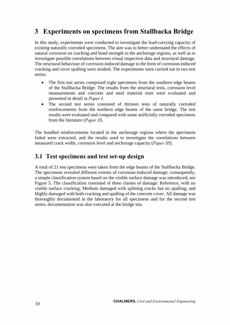
3.1 Test specimens and test set-up design A total of 21 test specimens were taken from the edge beams of the Stallbacka Bridge. The specimens revealed different extents of corrosion-induced damage; consequently, a simple classification system based on the visible surface damage was introduced; see Figure 5. The classification consisted of three classes of damage: Reference, with no visible surface cracking; Medium damaged with splitting cracks but no spalling; and Highly damaged with both cracking and spalling of the concrete cover. All damage was thoroughly documented in the laboratory for all specimens and for the second test series, documentation was also executed at the bridge site.
CHALMERS, Civil and Environmental Engineering 11
Figure 5. Categorization of the specimens based on different extents of corrosion induced damage.
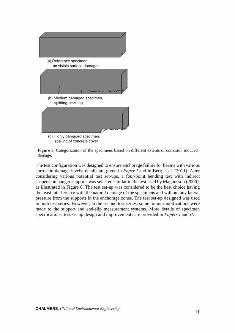
The test configuration was designed to ensure anchorage failure for beams with various corrosion damage levels; details are given in Paper I and in Berg et al. (2011). After considering various potential test set-ups, a four-point bending test with indirect suspension hanger supports was selected similar to the test used by Magnusson (2000), as illustrated in Figure 6. The test set-up was considered to be the best choice having the least interference with the natural damage of the specimens and without any lateral pressure from the supports in the anchorage zones. The test set-up designed was used in both test series. However, in the second test series, some minor modifications were made to the support and end-slip measurement systems. More details of specimen specifications, test set-up design and improvements are provided in Papers I and II.
CHALMERS, Civil and Environmental Engineering 12
Figure 6. Four-point bending test with indirect supports.
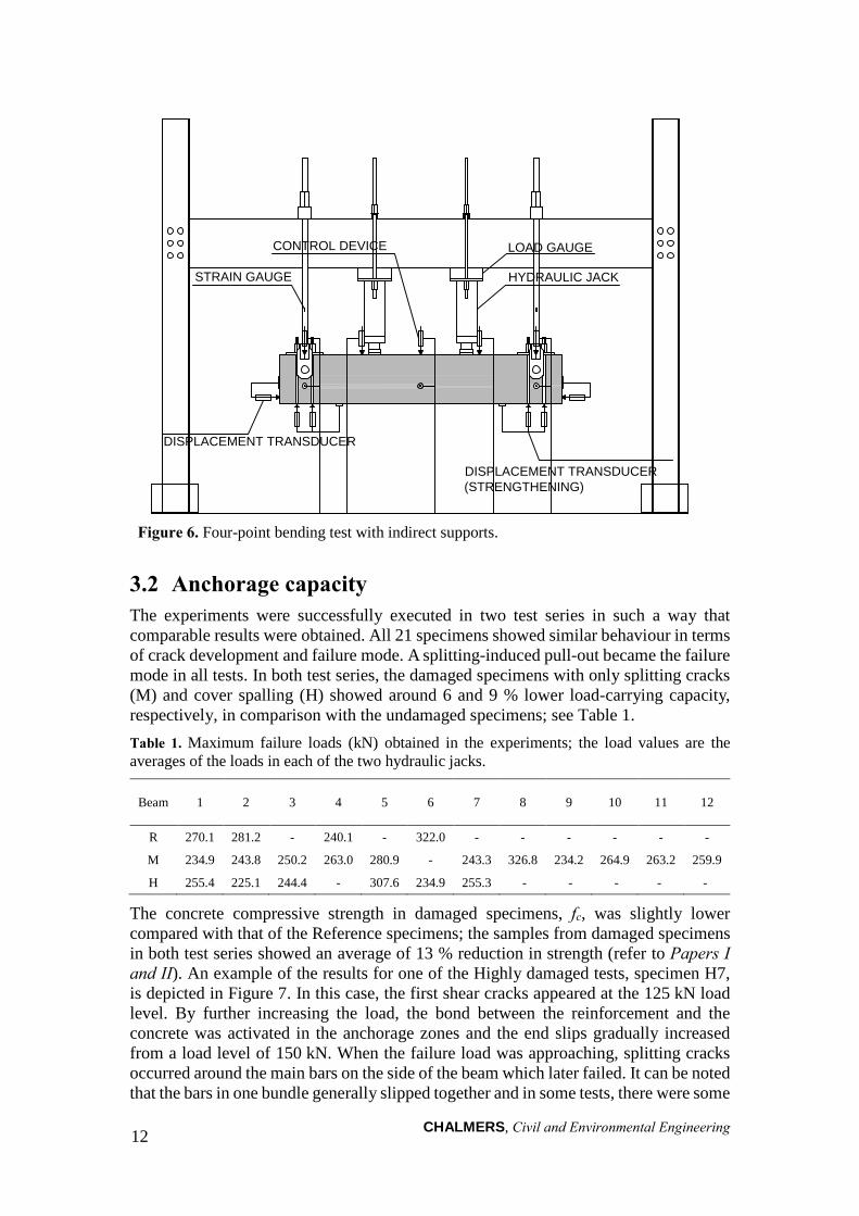
3.2 Anchorage capacity The experiments were successfully executed in two test series in such a way that comparable results were obtained. All 21 specimens showed similar behaviour in terms of crack development and failure mode. A splitting-induced pull-out became the failure mode in all tests. In both test series, the damaged specimens with only splitting cracks (M) and cover spalling (H) showed around 6 and 9 % lower load-carrying capacity,respectively, in comparison with the undamaged specimens; see Table 1.Table 1. Maximum failure loads (kN) obtained in the experiments; the load values are the averages of the loads in each of the two hydraulic jacks.
Beam 1 2 3 4 5 6 7 8 9 10 11 12
R 270.1 281.2 - 240.1 - 322.0 - - - - - -
M 234.9 243.8 250.2 263.0 280.9 - 243.3 326.8 234.2 264.9 263.2 259.9
H 255.4 225.1 244.4 - 307.6 234.9 255.3 - - - - -
The concrete compressive strength in damaged specimens, fc, was slightly lower compared with that of the Reference specimens; the samples from damaged specimens in both test series showed an average of 13 % reduction in strength (refer to Papers I and II). An example of the results for one of the Highly damaged tests, specimen H7, is depicted in Figure 7. In this case, the first shear cracks appeared at the 125 kN load level. By further increasing the load, the bond between the reinforcement and the concrete was activated in the anchorage zones and the end slips gradually increased from a load level of 150 kN. When the failure load was approaching, splitting cracks occurred around the main bars on the side of the beam which later failed. It can be noted that the bars in one bundle generally slipped together and in some tests, there were some
DISPLACEMENT TRANSDUCER
LOAD GAUGE
CONTROL DEVICE
STRAIN GAUGE HYDRAULIC JACK
DISPLACEMENT TRANSDUCER
(STRENGTHENING)
CHALMERS, Civil and Environmental Engineering 13
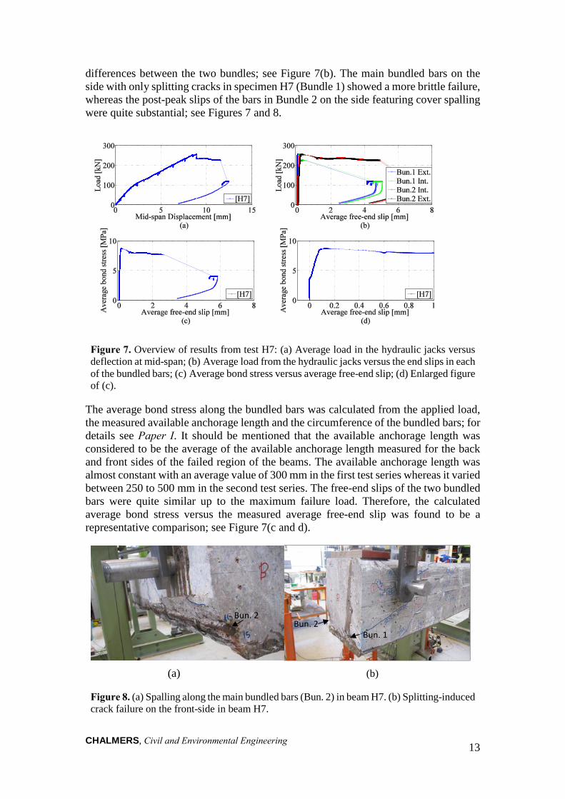
differences between the two bundles; see Figure 7(b). The main bundled bars on the side with only splitting cracks in specimen H7 (Bundle 1) showed a more brittle failure, whereas the post-peak slips of the bars in Bundle 2 on the side featuring cover spalling were quite substantial; see Figures 7 and 8.
Figure 7. Overview of results from test H7: (a) Average load in the hydraulic jacks versus deflection at mid-span; (b) Average load from the hydraulic jacks versus the end slips in each of the bundled bars; (c) Average bond stress versus average free-end slip; (d) Enlarged figure of (c).
The average bond stress along the bundled bars was calculated from the applied load, the measured available anchorage length and the circumference of the bundled bars; for details see Paper I. It should be mentioned that the available anchorage length was considered to be the average of the available anchorage length measured for the back and front sides of the failed region of the beams. The available anchorage length was almost constant with an average value of 300 mm in the first test series whereas it varied between 250 to 500 mm in the second test series. The free-end slips of the two bundled bars were quite similar up to the maximum failure load. Therefore, the calculated average bond stress versus the measured average free-end slip was found to be a representative comparison; see Figure 7(c and d).
(a) (b)
Figure 8. (a) Spalling along the main bundled bars (Bun. 2) in beam H7. (b) Splitting-induced crack failure on the front-side in beam H7.
Bun. 2
Bun. 1 Bun. 2
CHALMERS, Civil and Environmental Engineering
14
When looking at the results of both test series together provided in Table 2, the calculated average bond stress in the anchorage zone was about 20 % lower in the beams with corrosion cracks compared with the Reference specimens, whereas it was 12 % lower in the beams with cover spalling; more information is provided in Papers I and II. Table 2. Maximum average bond stress (in MPa) in the experiments.
Beam 1 2 3 4 5 6 7 8 9 10 11 12
R 9.8 9.8 - 9.4 - 7.2 - - - - - - M 7.9 9.4 7.4 6.2 6.6 - 7.9 9.3 6.9 8.0 5.2 5.2 H 8.5 8.0 9.8 - 6.9 6.0 8.7 - - - - -
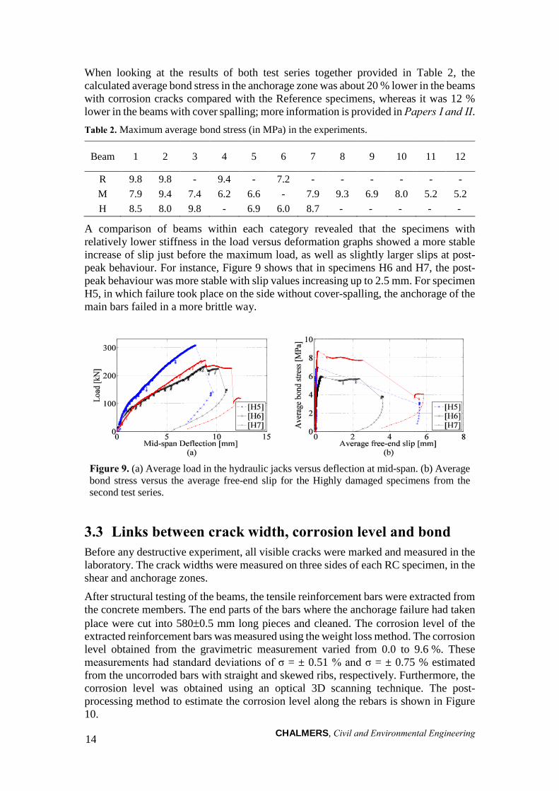
A comparison of beams within each category revealed that the specimens with relatively lower stiffness in the load versus deformation graphs showed a more stable increase of slip just before the maximum load, as well as slightly larger slips at post-peak behaviour. For instance, Figure 9 shows that in specimens H6 and H7, the post-peak behaviour was more stable with slip values increasing up to 2.5 mm. For specimen H5, in which failure took place on the side without cover-spalling, the anchorage of the main bars failed in a more brittle way.
Figure 9. (a) Average load in the hydraulic jacks versus deflection at mid-span. (b) Average bond stress versus the average free-end slip for the Highly damaged specimens from the second test series.
3.3 Links between crack width, corrosion level and bond Before any destructive experiment, all visible cracks were marked and measured in the laboratory. The crack widths were measured on three sides of each RC specimen, in the shear and anchorage zones.
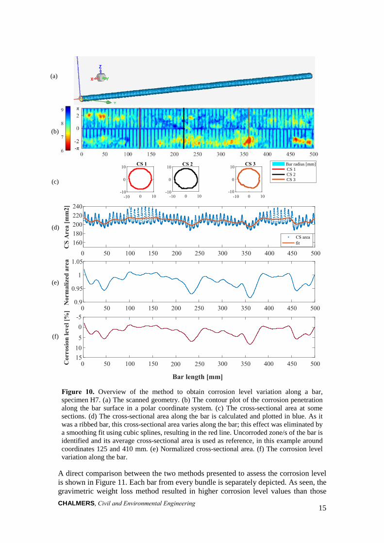
After structural testing of the beams, the tensile reinforcement bars were extracted from the concrete members. The end parts of the bars where the anchorage failure had taken place were cut into 580±0.5 mm long pieces and cleaned. The corrosion level of the extracted reinforcement bars was measured using the weight loss method. The corrosion level obtained from the gravimetric measurement varied from 0.0 to 9.6 %. These measurements had standard deviations of σ = ± 0.51 % and σ = ± 0.75 % estimated from the uncorroded bars with straight and skewed ribs, respectively. Furthermore, the corrosion level was obtained using an optical 3D scanning technique. The post-processing method to estimate the corrosion level along the rebars is shown in Figure 10.
CHALMERS, Civil and Environmental Engineering 15
Figure 10. Overview of the method to obtain corrosion level variation along a bar, specimen H7. (a) The scanned geometry. (b) The contour plot of the corrosion penetration along the bar surface in a polar coordinate system. (c) The cross-sectional area at some sections. (d) The cross-sectional area along the bar is calculated and plotted in blue. As it was a ribbed bar, this cross-sectional area varies along the bar; this effect was eliminated by a smoothing fit using cubic splines, resulting in the red line. Uncorroded zone/s of the bar is identified and its average cross-sectional area is used as reference, in this example around coordinates 125 and 410 mm. (e) Normalized cross-sectional area. (f) The corrosion level variation along the bar.
A direct comparison between the two methods presented to assess the corrosion level is shown in Figure 11. Each bar from every bundle is separately depicted. As seen, the gravimetric weight loss method resulted in higher corrosion level values than those
Bar length [mm]
-π
π
(a)
(b)
(c)
(d)
(e)
(f)
-10 0 10
0
10 CS 1
0 10
0
10 CS 2
0 10
0
10 CS 3
0 50 100 150 200 250 300 350 400 450 500
160180200220240
CS
Are
a [m
m2]
CS areafit
0 50 100 150 200 250 300 350 400 450 5000.9
0.95
1
1.05
Nor
mal
ized
are
a
0 50 100 150 200 250 300 350 400 450 500
-5
Cor
rosi
on le
vel [
%]
Bar radius [mm]CS 1CS 2CS 3
-10
-10 -10
-10 -10
0
5 10 15
CHALMERS, Civil and Environmental Engineering 16
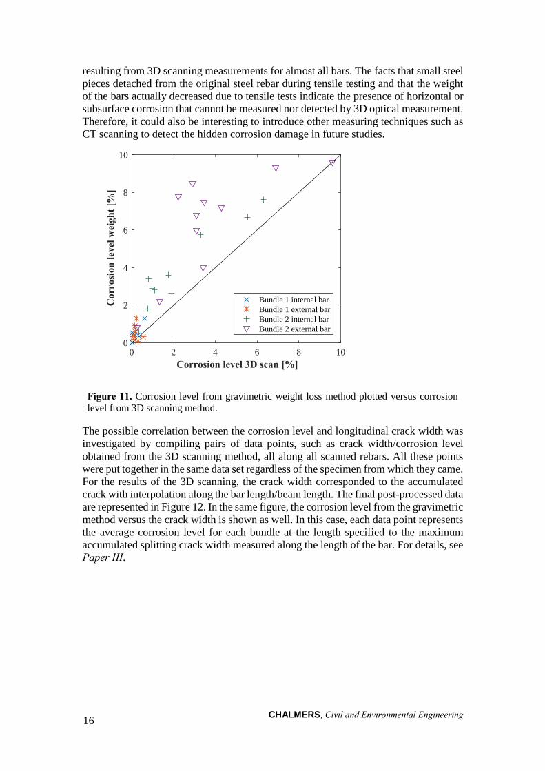
resulting from 3D scanning measurements for almost all bars. The facts that small steel pieces detached from the original steel rebar during tensile testing and that the weight of the bars actually decreased due to tensile tests indicate the presence of horizontal or subsurface corrosion that cannot be measured nor detected by 3D optical measurement. Therefore, it could also be interesting to introduce other measuring techniques such as CT scanning to detect the hidden corrosion damage in future studies.
Figure 11. Corrosion level from gravimetric weight loss method plotted versus corrosion level from 3D scanning method.
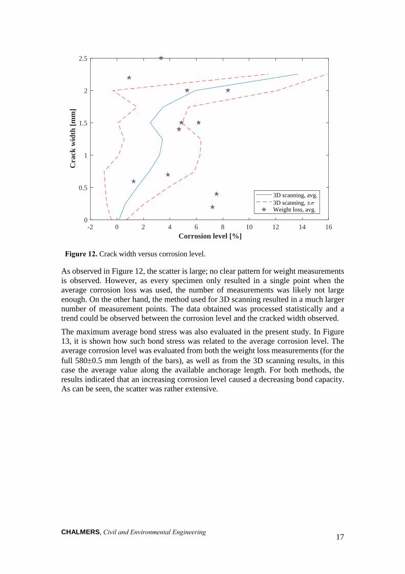
The possible correlation between the corrosion level and longitudinal crack width was investigated by compiling pairs of data points, such as crack width/corrosion level obtained from the 3D scanning method, all along all scanned rebars. All these points were put together in the same data set regardless of the specimen from which they came. For the results of the 3D scanning, the crack width corresponded to the accumulated crack with interpolation along the bar length/beam length. The final post-processed data are represented in Figure 12. In the same figure, the corrosion level from the gravimetric method versus the crack width is shown as well. In this case, each data point represents the average corrosion level for each bundle at the length specified to the maximum accumulated splitting crack width measured along the length of the bar. For details, see Paper III.
0 2 8 104 6Corrosion level 3D scan [%]
0
2
4
6
8
10
Cor
rosi
on le
vel w
eigh
t [%
]
Bundle 1 internal barBundle 1 external barBundle 2 internal barBundle 2 external bar
CHALMERS, Civil and Environmental Engineering 17
Figure 12. Crack width versus corrosion level.
As observed in Figure 12, the scatter is large; no clear pattern for weight measurements is observed. However, as every specimen only resulted in a single point when the average corrosion loss was used, the number of measurements was likely not large enough. On the other hand, the method used for 3D scanning resulted in a much larger number of measurement points. The data obtained was processed statistically and a trend could be observed between the corrosion level and the cracked width observed.
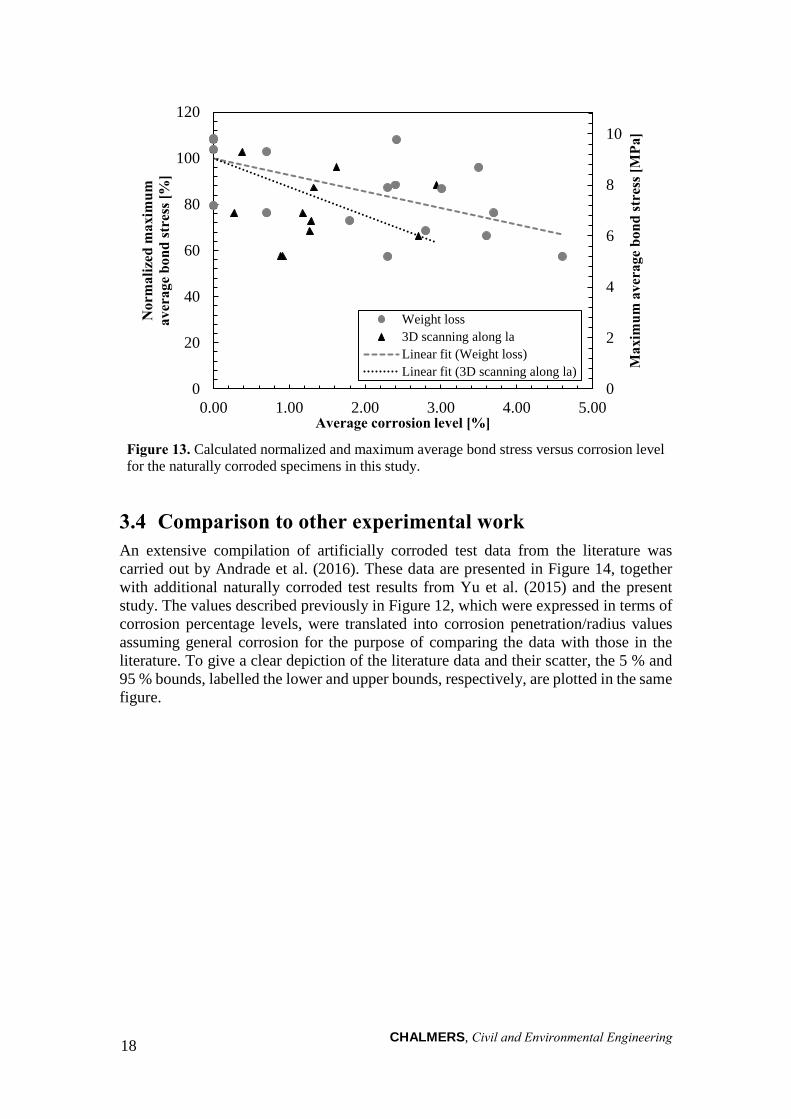
The maximum average bond stress was also evaluated in the present study. In Figure 13, it is shown how such bond stress was related to the average corrosion level. The average corrosion level was evaluated from both the weight loss measurements (for the full 580±0.5 mm length of the bars), as well as from the 3D scanning results, in this case the average value along the available anchorage length. For both methods, the results indicated that an increasing corrosion level caused a decreasing bond capacity. As can be seen, the scatter was rather extensive.
0
0.5
1
1.5
2
2.5
Cra
ck w
idth
[m
m]
-2 0 2 4 10 12 14 166 8Corrosion level [%]
3D scanning, avg.3D scanning, ±<Weight loss, avg.
CHALMERS, Civil and Environmental Engineering 18
Figure 13. Calculated normalized and maximum average bond stress versus corrosion level for the naturally corroded specimens in this study.
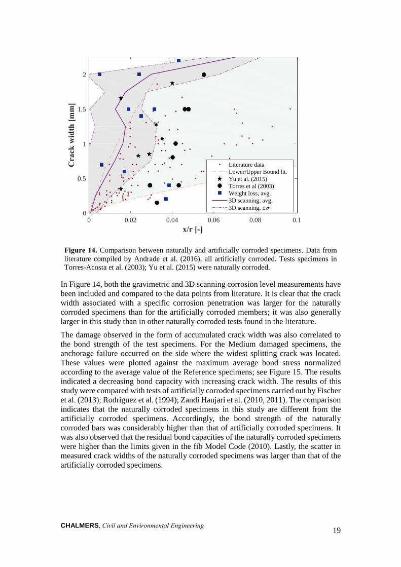
3.4 Comparison to other experimental work An extensive compilation of artificially corroded test data from the literature was carried out by Andrade et al. (2016). These data are presented in Figure 14, together with additional naturally corroded test results from Yu et al. (2015) and the present study. The values described previously in Figure 12, which were expressed in terms of corrosion percentage levels, were translated into corrosion penetration/radius values assuming general corrosion for the purpose of comparing the data with those in the literature. To give a clear depiction of the literature data and their scatter, the 5 % and 95 % bounds, labelled the lower and upper bounds, respectively, are plotted in the same figure.
0
2
4
6
8
10
0
20
40
60
80
100
120
0.00 1.00 2.00 3.00 4.00 5.00
Max
imum
ave
rage
bon
d st
ress
[MPa
]
Nor
mal
ized
max
imum
av
erag
e bo
nd st
ress
[%]
Average corrosion level [%]
Weight loss3D scanning along laLinear fit (Weight loss)Linear fit (3D scanning along la)
CHALMERS, Civil and Environmental Engineering 19
Figure 14. Comparison between naturally and artificially corroded specimens. Data from literature compiled by Andrade et al. (2016), all artificially corroded. Tests specimens in Torres-Acosta et al. (2003); Yu et al. (2015) were naturally corroded.
In Figure 14, both the gravimetric and 3D scanning corrosion level measurements have been included and compared to the data points from literature. It is clear that the crack width associated with a specific corrosion penetration was larger for the naturally corroded specimens than for the artificially corroded members; it was also generally larger in this study than in other naturally corroded tests found in the literature.
The damage observed in the form of accumulated crack width was also correlated to the bond strength of the test specimens. For the Medium damaged specimens, the anchorage failure occurred on the side where the widest splitting crack was located. These values were plotted against the maximum average bond stress normalized according to the average value of the Reference specimens; see Figure 15. The results indicated a decreasing bond capacity with increasing crack width. The results of this study were compared with tests of artificially corroded specimens carried out by Fischer et al. (2013); Rodriguez et al. (1994); Zandi Hanjari et al. (2010, 2011). The comparison indicates that the naturally corroded specimens in this study are different from the artificially corroded specimens. Accordingly, the bond strength of the naturally corroded bars was considerably higher than that of artificially corroded specimens. It was also observed that the residual bond capacities of the naturally corroded specimens were higher than the limits given in the fib Model Code (2010). Lastly, the scatter in measured crack widths of the naturally corroded specimens was larger than that of the artificially corroded specimens.
0 0.02 0.04 0.06 0.08 0.10
0.5
1
1.5
2m
]C
rack
wid
th [m
Literature dataLower/Upper Bound lit.Yu et al. (2015)Torres et al (2003)Weight loss, avg.3D scanning, avg.3D scanning, ±<
x/r [-]

CHALMERS, Civil and Environmental Engineering
20
Figure 15. Comparison between test results from naturally corroded specimens and results from artificially corroded tests and fib Model Code (2010) in terms of bond strength, normalized with respect to the average maximum bond strength obtained from reference samples, versus maximum crack width of splitting cracks.
The experimental studies selected for comparison slightly differed in terms of corrosion environment. For instance, the corrosion rate for the specimens taken from the field was much lower than that of artificially corroded specimens. The rate was estimated to be approximately 1.2 µA/cm2 for the naturally corroded specimens. This value was estimated based on the maximum average 9.6% weight loss of the reinforcement bars during 32 years of exposure to a corrosive environment (Paper III). This estimation was carried out using the steel corrosion-rate conversion factor given in (Roberge 2008). This estimated value was lower than the natural corrosion rates of 10-25 µA/cm2
obtained from field measurements in chloride contaminated concrete structures; see CEB-fib (2000). Conversely, the corrosion rates were much higher in the artificially corroded tests, varying from 100 to 2000 µA/cm2; see Table 3 and Paper III. The geometrical parameters of the specimens in the tests also differed as did the test methods, e.g. the cover thickness was constant in almost all artificially corroded specimens, whereas it varied in the naturally corroded specimens. In the artificial corrosion tests, bars of the specimens were pulled out one at a time in the pull-out test set-ups, whereas for the naturally corroded specimens two bundles were pulled out simultaneously in a bending test configuration.
The measured available anchorage length in the naturally corroded specimens varied between 250 to 500 mm whereas in the accelerated corrosion tests, this parameter was always less than 210 mm. Furthermore, the artificially corroded specimens contained a higher amount of stirrups and the specimens in the present study had more widely spaced transverse reinforcement bars than other test series. Despite these differences, higher bond stresses for the same crack width were obtained in the naturally corroded tests than in the artificially corroded specimens.
R² = 0.4255R² = 0.2796
R² = 0.71
R² = 0.8262
0
20
40
60
80
100
120
0.0 0.5 1.0 1.5 2.0 2.5
Nor
mal
ized
max
imum
ave
rage
bon
d st
ress
[%]
Accumulated crack width [mm]
Natural Corrosion (Present study)Artificial Corrosion (Zandi et al, 2010)Artificial Corrosion (Rodriguez et al, 1994)Artificial Corrosion (Fischer C. et al, 2013)Model Code 2010: Lower limitModel Code 2010: Upper limitRegression, Natural (Present study)Regression, Artificial (Zandi et al, 2010)Regression, Artificial (Rodriguez et al, 1994)Regression, Artificial (Fischer C. et al, 2013)
CHALMERS, Civil and Environmental Engineering 21
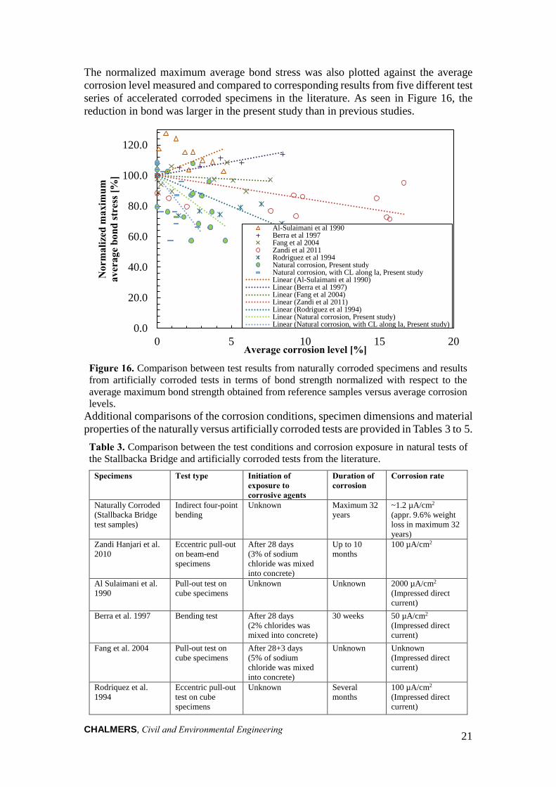
The normalized maximum average bond stress was also plotted against the average corrosion level measured and compared to corresponding results from five different test series of accelerated corroded specimens in the literature. As seen in Figure 16, the reduction in bond was larger in the present study than in previous studies.
Figure 16. Comparison between test results from naturally corroded specimens and results from artificially corroded tests in terms of bond strength normalized with respect to the average maximum bond strength obtained from reference samples versus average corrosion levels.
Additional comparisons of the corrosion conditions, specimen dimensions and material properties of the naturally versus artificially corroded tests are provided in Tables 3 to 5. Table 3. Comparison between the test conditions and corrosion exposure in natural tests of the Stallbacka Bridge and artificially corroded tests from the literature.
Specimens Test type Initiation of exposure to corrosive agents
Duration of corrosion
Corrosion rate
Naturally Corroded (Stallbacka Bridge test samples)
Indirect four-point bending
Unknown Maximum 32 years
~1.2 µA/cm2
(appr. 9.6% weight loss in maximum 32 years)
Zandi Hanjari et al. 2010
Eccentric pull-out on beam-end specimens
After 28 days (3% of sodium chloride was mixed into concrete)
Up to 10 months
100 µA/cm2
Al Sulaimani et al. 1990
Pull-out test on cube specimens
Unknown Unknown 2000 µA/cm2
(Impressed direct current)
Berra et al. 1997 Bending test After 28 days (2% chlorides was mixed into concrete)
30 weeks 50 µA/cm2 (Impressed direct current)
Fang et al. 2004 Pull-out test on cube specimens
After 28+3 days (5% of sodium chloride was mixed into concrete)
Unknown Unknown (Impressed direct current)
Rodriquez et al. 1994
Eccentric pull-out test on cube specimens
Unknown Several months
100 µA/cm2
(Impressed direct current)
0.0
20.0
40.0
60.0
80.0
100.0
120.0
0 5 10 15 20
Nor
mal
ized
max
imum
av
erag
e bo
nd st
ress
[%]
Average corrosion level [%]
Al-Sulaimani et al 1990Berra et al 1997Fang et al 2004Zandi et al 2011Rodriguez et al 1994Natural corrosion, Present studyNatural corrosion, with CL along la, Present studyLinear (Al-Sulaimani et al 1990)Linear (Berra et al 1997)Linear (Fang et al 2004)Linear (Zandi et al 2011)Linear (Rodriguez et al 1994)Linear (Natural corrosion, Present study)Linear (Natural corrosion, with CL along la, Present study)
CHALMERS, Civil and Environmental Engineering
22
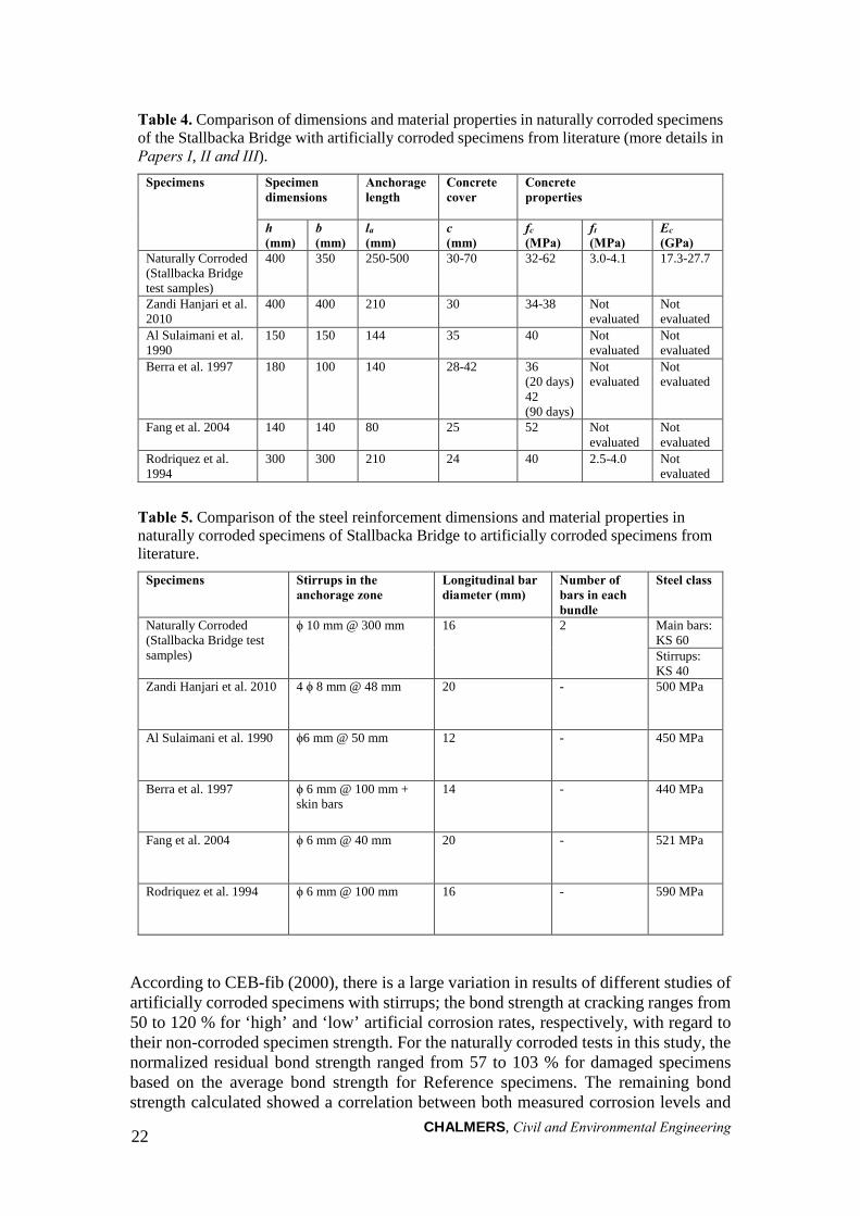
Table 4. Comparison of dimensions and material properties in naturally corroded specimens of the Stallbacka Bridge with artificially corroded specimens from literature (more details in Papers I, II and III).
Specimens Specimen dimensions
Anchorage length
Concrete cover
Concrete properties
h (mm)
b (mm)
la (mm)
c (mm)
fc (MPa)
ft (MPa)
Ec (GPa)
Naturally Corroded (Stallbacka Bridge test samples)
400 350 250-500 30-70 32-62 3.0-4.1 17.3-27.7
Zandi Hanjari et al. 2010
400 400 210 30 34-38 Not evaluated
Not evaluated
Al Sulaimani et al. 1990
150 150 144 35 40 Not evaluated
Not evaluated
Berra et al. 1997 180 100 140 28-42 36 (20 days) 42 (90 days)
Not evaluated
Not evaluated
Fang et al. 2004 140 140 80 25 52 Not evaluated
Not evaluated
Rodriquez et al. 1994
300 300 210 24 40 2.5-4.0 Not evaluated
Table 5. Comparison of the steel reinforcement dimensions and material properties in naturally corroded specimens of Stallbacka Bridge to artificially corroded specimens from literature.
Specimens Stirrups in the anchorage zone
Longitudinal bar diameter (mm)
Number of bars in each bundle
Steel class
Naturally Corroded (Stallbacka Bridge test samples)
ϕ 10 mm @ 300 mm 16 2 Main bars: KS 60 Stirrups: KS 40
Zandi Hanjari et al. 2010 4 ϕ 8 mm @ 48 mm 20 - 500 MPa
Al Sulaimani et al. 1990 ϕ6 mm @ 50 mm 12 - 450 MPa
Berra et al. 1997 ϕ 6 mm @ 100 mm + skin bars
14 - 440 MPa
Fang et al. 2004 ϕ 6 mm @ 40 mm 20 - 521 MPa
Rodriquez et al. 1994 ϕ 6 mm @ 100 mm 16 - 590 MPa
According to CEB-fib (2000), there is a large variation in results of different studies of artificially corroded specimens with stirrups; the bond strength at cracking ranges from 50 to 120 % for ‘high’ and ‘low’ artificial corrosion rates, respectively, with regard to their non-corroded specimen strength. For the naturally corroded tests in this study, the normalized residual bond strength ranged from 57 to 103 % for damaged specimens based on the average bond strength for Reference specimens. The remaining bond strength calculated showed a correlation between both measured corrosion levels and
CHALMERS, Civil and Environmental Engineering
23
crack widths in all naturally and artificially corroded specimens. However, the scatter was large.
The crack widths that may lead to cover spalling could also be correlated to the structural effects of corrosion damage. Some researchers report crack widths in excess of 0.6 mm without spalling, whereas Rodriguez et al. (1994) and Torres-Acosta et al. (2003) observed that the concrete cover did not spall even when cracks reached 2 mm in width. In the naturally corroded specimens from Stallbacka Bridge, it was observed that splitting cracks widened up to 2.5 mm with no signs of concrete cover spalling.
The results from this study and previous literature indicate that the corrosion level could be estimated based on the crack widths measured. In cases when estimations derive from results of artificially corroded specimens, the corrosion level in the naturally corroded specimens would be greatly overestimated. This finding agrees with the research by Andrade et al. (1993) who discovered that for the same corrosion level with low corrosion rates, larger crack widths would appear on concrete surfaces. However, this is contrary to results reported by Coronelli et al. (2011) who had indicated that the slower the corrosion rates, the smaller the crack widths. This finding appears reasonable as a smaller corrosion rate allows for corrosion products to flow out through cracks, thereby reducing splitting pressure. Thus, other effects were recognized as possible explanations for the large crack widths observed in naturally corroded specimens. These effects included the combined corrosion and freezing, as well as other long-term effects, such as creep and shrinkage of the concrete.
CHALMERS, Civil and Environmental Engineering
24
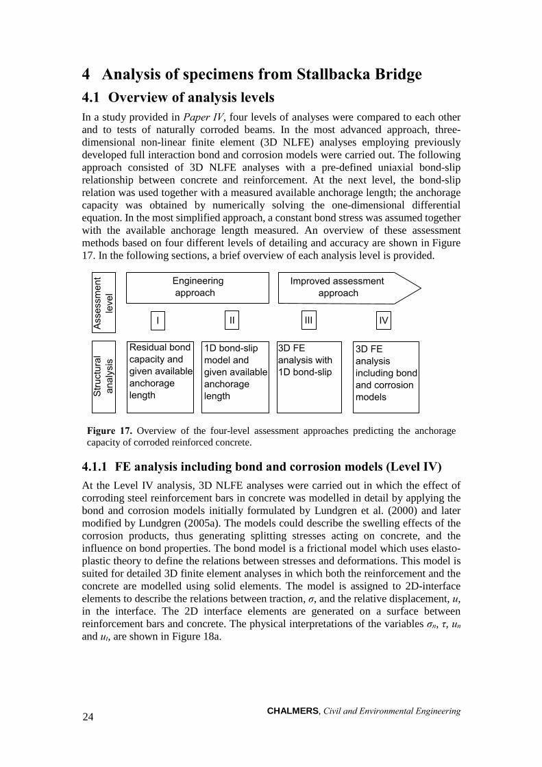
4 Analysis of specimens from Stallbacka Bridge 4.1 Overview of analysis levels In a study provided in Paper IV, four levels of analyses were compared to each other and to tests of naturally corroded beams. In the most advanced approach, three-dimensional non-linear finite element (3D NLFE) analyses employing previously developed full interaction bond and corrosion models were carried out. The following approach consisted of 3D NLFE analyses with a pre-defined uniaxial bond-slip relationship between concrete and reinforcement. At the next level, the bond-slip relation was used together with a measured available anchorage length; the anchorage capacity was obtained by numerically solving the one-dimensional differential equation. In the most simplified approach, a constant bond stress was assumed together with the available anchorage length measured. An overview of these assessment methods based on four different levels of detailing and accuracy are shown in Figure 17. In the following sections, a brief overview of each analysis level is provided.
Figure 17. Overview of the four-level assessment approaches predicting the anchorage capacity of corroded reinforced concrete.
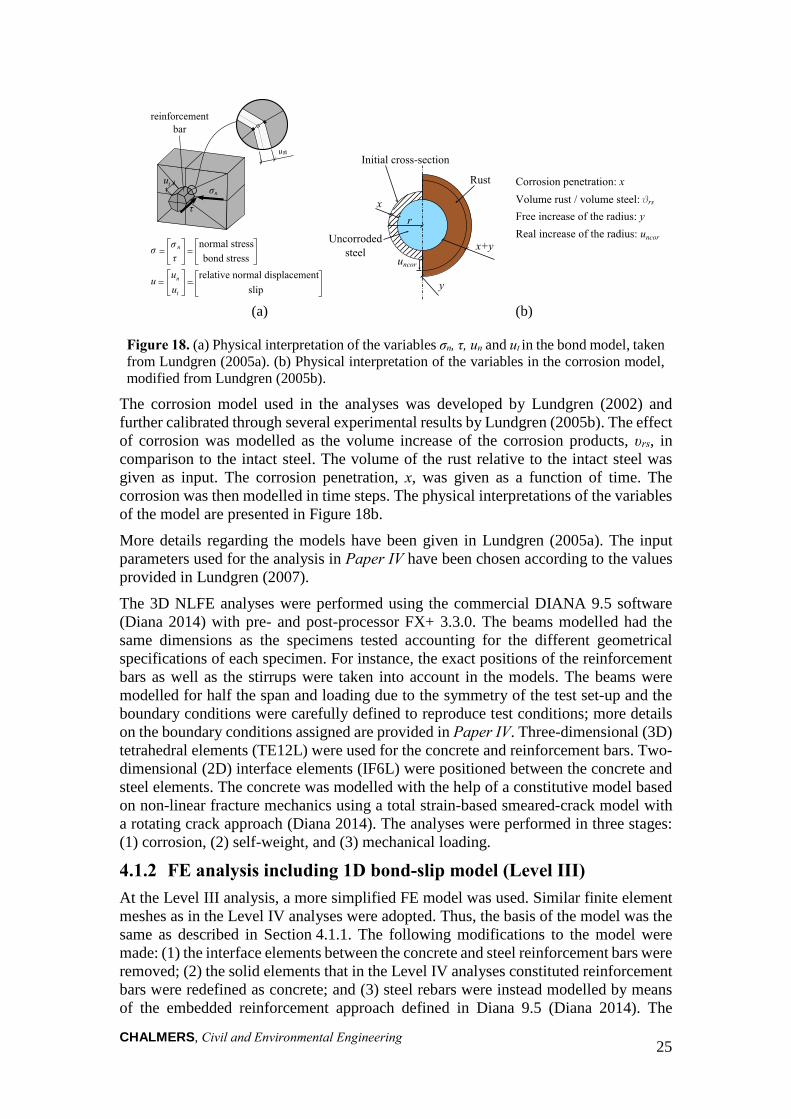
4.1.1 FE analysis including bond and corrosion models (Level IV) At the Level IV analysis, 3D NLFE analyses were carried out in which the effect of corroding steel reinforcement bars in concrete was modelled in detail by applying the bond and corrosion models initially formulated by Lundgren et al. (2000) and later modified by Lundgren (2005a). The models could describe the swelling effects of the corrosion products, thus generating splitting stresses acting on concrete, and the influence on bond properties. The bond model is a frictional model which uses elasto-plastic theory to define the relations between stresses and deformations. This model is suited for detailed 3D finite element analyses in which both the reinforcement and the concrete are modelled using solid elements. The model is assigned to 2D-interface elements to describe the relations between traction, σ, and the relative displacement, u, in the interface. The 2D interface elements are generated on a surface between reinforcement bars and concrete. The physical interpretations of the variables σn, τ, un and ut, are shown in Figure 18a.
CHALMERS, Civil and Environmental Engineering
25
(a) (b)
Figure 18. (a) Physical interpretation of the variables σn, τ, un and ut in the bond model, taken from Lundgren (2005a). (b) Physical interpretation of the variables in the corrosion model, modified from Lundgren (2005b).
The corrosion model used in the analyses was developed by Lundgren (2002) and further calibrated through several experimental results by Lundgren (2005b). The effect of corrosion was modelled as the volume increase of the corrosion products, υrs, in comparison to the intact steel. The volume of the rust relative to the intact steel was given as input. The corrosion penetration, x, was given as a function of time. The corrosion was then modelled in time steps. The physical interpretations of the variables of the model are presented in Figure 18b.
More details regarding the models have been given in Lundgren (2005a). The input parameters used for the analysis in Paper IV have been chosen according to the values provided in Lundgren (2007).
The 3D NLFE analyses were performed using the commercial DIANA 9.5 software (Diana 2014) with pre- and post-processor FX+ 3.3.0. The beams modelled had the same dimensions as the specimens tested accounting for the different geometrical specifications of each specimen. For instance, the exact positions of the reinforcement bars as well as the stirrups were taken into account in the models. The beams were modelled for half the span and loading due to the symmetry of the test set-up and the boundary conditions were carefully defined to reproduce test conditions; more details on the boundary conditions assigned are provided in Paper IV. Three-dimensional (3D) tetrahedral elements (TE12L) were used for the concrete and reinforcement bars. Two-dimensional (2D) interface elements (IF6L) were positioned between the concrete and steel elements. The concrete was modelled with the help of a constitutive model based on non-linear fracture mechanics using a total strain-based smeared-crack model with a rotating crack approach (Diana 2014). The analyses were performed in three stages: (1) corrosion, (2) self-weight, and (3) mechanical loading.
4.1.2 FE analysis including 1D bond-slip model (Level III) At the Level III analysis, a more simplified FE model was used. Similar finite element meshes as in the Level IV analyses were adopted. Thus, the basis of the model was the same as described in Section 4.1.1. The following modifications to the model were made: (1) the interface elements between the concrete and steel reinforcement bars were removed; (2) the solid elements that in the Level IV analyses constituted reinforcement bars were redefined as concrete; and (3) steel rebars were instead modelled by means of the embedded reinforcement approach defined in Diana 9.5 (Diana 2014). The
CHALMERS, Civil and Environmental Engineering
26
interaction between the concrete and embedded reinforcement was defined using the 1D bond-slip model suggested by Lundgren et al. (2012).
The 1D bond-slip model was based on the local bond-slip defined in fib Model Code (1990). The specimen parameters, such as the amount of transversal reinforcement, concrete cover, diameter of the anchored reinforcement, concrete compressive strength and the corrosion degree measured were taken into account.
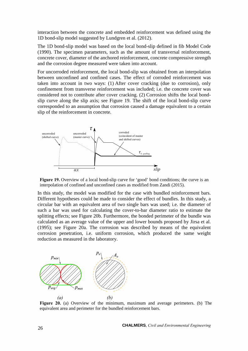
For uncorroded reinforcement, the local bond-slip was obtained from an interpolation between unconfined and confined cases. The effect of corroded reinforcement was taken into account in two ways: (1) After cover cracking (due to corrosion), only confinement from transverse reinforcement was included; i.e. the concrete cover was considered not to contribute after cover cracking. (2) Corrosion shifts the local bond-slip curve along the slip axis; see Figure 19. The shift of the local bond-slip curve corresponded to an assumption that corrosion caused a damage equivalent to a certain slip of the reinforcement in concrete.
Figure 19. Overview of a local bond-slip curve for ‘good’ bond conditions; the curve is an interpolation of confined and unconfined cases as modified from Zandi (2015).
In this study, the model was modified for the case with bundled reinforcement bars. Different hypotheses could be made to consider the effect of bundles. In this study, a circular bar with an equivalent area of two single bars was used; i.e. the diameter of such a bar was used for calculating the cover-to-bar diameter ratio to estimate the splitting effects; see Figure 20b. Furthermore, the bonded perimeter of the bundle was calculated as an average value of the upper and lower bounds proposed by Jirsa et al. (1995); see Figure 20a. The corrosion was described by means of the equivalent corrosion penetration, i.e. uniform corrosion, which produced the same weight reduction as measured in the laboratory.
(a) (b) Figure 20. (a) Overview of the minimum, maximum and average perimeters. (b) The equivalent area and perimeter for the bundled reinforcement bars.
CHALMERS, Civil and Environmental Engineering 27
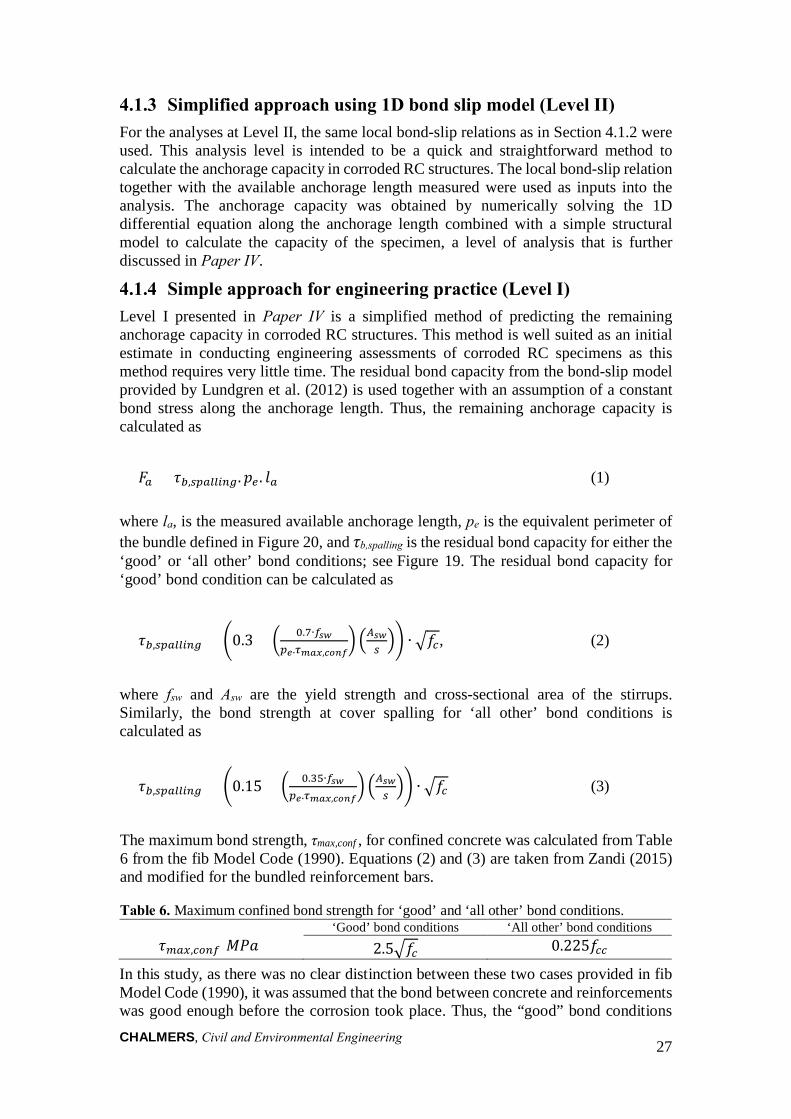
4.1.3 Simplified approach using 1D bond slip model (Level II) For the analyses at Level II, the same local bond-slip relations as in Section 4.1.2 were used. This analysis level is intended to be a quick and straightforward method to calculate the anchorage capacity in corroded RC structures. The local bond-slip relation together with the available anchorage length measured were used as inputs into the analysis. The anchorage capacity was obtained by numerically solving the 1D differential equation along the anchorage length combined with a simple structural model to calculate the capacity of the specimen, a level of analysis that is further discussed in Paper IV.
4.1.4 Simple approach for engineering practice (Level I) Level I presented in Paper IV is a simplified method of predicting the remaining anchorage capacity in corroded RC structures. This method is well suited as an initial estimate in conducting engineering assessments of corroded RC specimens as this method requires very little time. The residual bond capacity from the bond-slip model provided by Lundgren et al. (2012) is used together with an assumption of a constant bond stress along the anchorage length. Thus, the remaining anchorage capacity is calculated as
𝐹𝐹𝑎𝑎 = 𝜏𝜏𝑏𝑏,𝑠𝑠𝑠𝑠𝑎𝑎𝑠𝑠𝑠𝑠𝑠𝑠𝑠𝑠𝑠𝑠.𝑝𝑝𝑒𝑒 . 𝑙𝑙𝑎𝑎 (1)
where la, is the measured available anchorage length, pe is the equivalent perimeter of the bundle defined in Figure 20, and τb,spalling is the residual bond capacity for either the ‘good’ or ‘all other’ bond conditions; see Figure 19. The residual bond capacity for ‘good’ bond condition can be calculated as
𝜏𝜏𝑏𝑏,𝑠𝑠𝑠𝑠𝑎𝑎𝑠𝑠𝑠𝑠𝑠𝑠𝑠𝑠𝑠𝑠 = �0.3 + � 0.7∙𝑓𝑓𝑠𝑠𝑠𝑠𝑠𝑠𝑒𝑒.𝜏𝜏𝑚𝑚𝑚𝑚𝑚𝑚,𝑐𝑐𝑐𝑐𝑐𝑐𝑐𝑐
� �𝐴𝐴𝑠𝑠𝑠𝑠𝑠𝑠�� ∙ �𝑓𝑓𝑐𝑐, (2)
where fsw and Asw are the yield strength and cross-sectional area of the stirrups. Similarly, the bond strength at cover spalling for ‘all other’ bond conditions is calculated as
𝜏𝜏𝑏𝑏,𝑠𝑠𝑠𝑠𝑎𝑎𝑠𝑠𝑠𝑠𝑠𝑠𝑠𝑠𝑠𝑠 = �0.15 + � 0.35∙𝑓𝑓𝑠𝑠𝑠𝑠𝑠𝑠𝑒𝑒.𝜏𝜏𝑚𝑚𝑚𝑚𝑚𝑚,𝑐𝑐𝑐𝑐𝑐𝑐𝑐𝑐
� �𝐴𝐴𝑠𝑠𝑠𝑠𝑠𝑠�� ∙ �𝑓𝑓𝑐𝑐 (3)
‘Good’ bond conditions ‘All other’ bond conditions 𝜏𝜏𝑚𝑚𝑎𝑎𝑚𝑚,𝑐𝑐𝑐𝑐𝑠𝑠𝑓𝑓[𝑀𝑀𝑀𝑀𝑀𝑀] 2.5�𝑓𝑓𝑐𝑐 0.225𝑓𝑓𝑐𝑐𝑐𝑐
The maximum bond strength, τmax,conf , for confined concrete was calculated from Table 6 from the fib Model Code (1990). Equations (2) and (3) are taken from Zandi (2015) and modified for the bundled reinforcement bars.
Table 6. Maximum confined bond strength for ‘good’ and ‘all other’ bond conditions.
In this study, as there was no clear distinction between these two cases provided in fib Model Code (1990), it was assumed that the bond between concrete and reinforcements was good enough before the corrosion took place. Thus, the “good” bond conditions
CHALMERS, Civil and Environmental Engineering
28
was assumed for the analyses. The same simple structural model as for Level III was used to link the anchorage capacity to the applied load; see Paper IV.
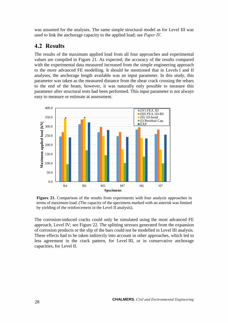
4.2 Results The results of the maximum applied load from all four approaches and experimental values are compiled in Figure 21. As expected, the accuracy of the results compared with the experimental data measured increased from the simple engineering approach to the more advanced FE modelling. It should be mentioned that in Levels I and II analyses, the anchorage length available was an input parameter. In this study, this parameter was taken as the measured distance from the shear crack crossing the rebars to the end of the beam, however, it was naturally only possible to measure this parameter after structural tests had been performed. This input parameter is not always easy to measure or estimate at assessment.
Figure 21. Comparison of the results from experiments with four analysis approaches in terms of maximum load. (The capacity of the specimens marked with an asterisk was limited by yielding of the reinforcement in the Level II analysis).
The corrosion-induced cracks could only be simulated using the most advanced FE approach, Level IV; see Figure 22. The splitting stresses generated from the expansion of corrosion products or the slip of the bars could not be modelled in Level III analysis. These effects had to be taken indirectly into account in other approaches, which led to less agreement in the crack pattern, for Level III, or in conservative anchorage capacities, for Level II.
0.0
50.0
100.0
150.0
200.0
250.0
300.0
350.0
400.0
R4 R6 M5 M7 H6 H7
Max
imum
app
lied
load
[kN
]
Specimens
(IV) FEA 3D(III) FEA 1D-BS(II) 1D-bond(I) Residual Cap.EXP
* *
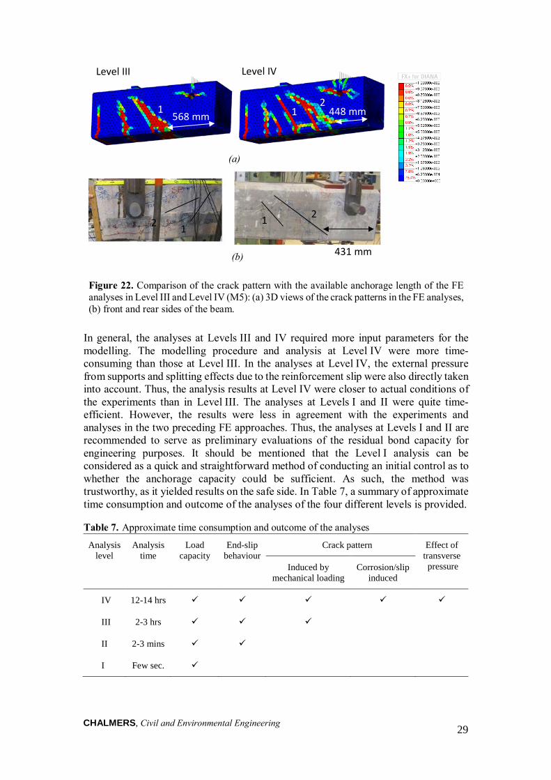
CHALMERS, Civil and Environmental Engineering 29
(a)
(b)
Analysis level
Analysis time
Load capacity
End-slip behaviour
Crack pattern Effect of transverse pressure Induced by
mechanical loading Corrosion/slip
induced
IV 12-14 hrs
III 2-3 hrs
II 2-3 mins
I Few sec.
568 mm 1 2
Level III Level IV
1
1 2 2 1
431 mm
1 1 2
568 mm 448 mm
Figure 22. Comparison of the crack pattern with the available anchorage length of the FE analyses in Level III and Level IV (M5): (a) 3D views of the crack patterns in the FE analyses, (b) front and rear sides of the beam.
In general, the analyses at Levels III and IV required more input parameters for the modelling. The modelling procedure and analysis at Level IV were more time-consuming than those at Level III. In the analyses at Level IV, the external pressure from supports and splitting effects due to the reinforcement slip were also directly taken into account. Thus, the analysis results at Level IV were closer to actual conditions of the experiments than in Level III. The analyses at Levels I and II were quite time-efficient. However, the results were less in agreement with the experiments and analyses in the two preceding FE approaches. Thus, the analyses at Levels I and II are recommended to serve as preliminary evaluations of the residual bond capacity for engineering purposes. It should be mentioned that the Level I analysis can be considered as a quick and straightforward method of conducting an initial control as to whether the anchorage capacity could be sufficient. As such, the method was trustworthy, as it yielded results on the safe side. In Table 7, a summary of approximate time consumption and outcome of the analyses of the four different levels is provided.
Table 7. Approximate time consumption and outcome of the analyses
CHALMERS, Civil and Environmental Engineering
30
5 Conclusions
5.1 General conclusions The aim of this study has been to deepen the understanding of the structural effects of natural corrosion deterioration with a focus on the remaining anchorage capacity between deformed bars and concrete, as well as investigating the possible links between visual inspection data and structural damage. In the initial part of the study, the effects of natural corrosion damage on bond behaviour and anchorage capacity of reinforcement in concrete were investigated in an experimental programme. The tests were focused on the bond behaviour between corroded ribbed rebars and concrete in the anchorage regions of reinforced concrete beams. Based on the outcome of the experimental work, the following conclusions were drawn:
• A test set-up was designed for the evaluation of anchorage capacity in RC specimens taken from existing structures. It worked properly as the expected failure mode, a splitting-induced pull-out failure, occurred in all experiments.
• The test results for the damaged specimens with only splitting cracks (M) and cover spalling (H) showed 6 and 9 % reduction in load-carrying capacity, respectively, in comparison with the Reference specimens.
• The average calculated bond stress in the anchorage zone was reduced by about 20 % for the specimens with only splitting cracks and 12 % for the specimens with cover spalling in comparison with the average Reference specimens.
• The concrete compressive strength measured was slightly lower in the damaged specimens in comparison with the Reference specimens; this could have influenced the damage level.
After the structural tests, the corrosion level was quantified using two different measuring methods, the gravimetric measurements and advanced optical 3D scanning. The correlations between the corrosion levels measured, splitting crack widths and anchorage capacity of the corroded specimens were investigated and the results were compared to artificial corrosion tests from the literature. The most significant conclusions of the evaluations and comparisons are listed below:
• Corrosion levels evaluated using the weight loss method yielded values approximately twice as large as those of 3D scanning. The presence of horizontal or subsurface corrosion that could not be measured nor detected by 3D optical measurement was supposedly the reason for the differences. It could be interesting to introduce other measuring techniques such as CT scanning to detect hidden corrosion damage.
• The 3D scanning method proved to be advantageous to describe corrosion patterns on the steel bar surface, as well as the longitudinal variation of the corrosion level; thereby it was possible to find correlations between measured crack widths and corrosion levels.
• It was observed that for the same corrosion level, the specimens in this study featured much larger crack widths than those of tests in the literature.
• The results indicated that the average bond strength of the naturally corroded bars was related to the maximum crack widths observed. A comparison of these results against the artificially corroded specimens and the provisions given in the fib
CHALMERS, Civil and Environmental Engineering
31
Model Code (2010) indicated that the naturally corroded tests yielded higher bond strength.
• Related to the corrosion level, the reduction in bond was larger in the present study than in other studies found in the literature, all with artificially induced corrosion. The combined effects of freezing and corrosion offer an explanation, but it should also be noted that there were stirrups with larger distance in the present study which definitely offers another possible explanation.
• Comparisons between the test results of naturally and artificially corroded specimens indicated that by using knowledge of artificial corrosion as a basis for formulating a damage indicator in the form of crack widths, estimations of the structural capacity would be on the safe side.
The results obtained from tests of naturally corroded specimens were used to examine available analysis methods calibrated with artificial corrosion tests. Thus, structural analyses were carried out on different levels and compared with each other. The structural assessments ranged from non-linear finite element analysis with three-dimensional solid models to a simplified approach considering the residual bond capacity of corroded bars. The main conclusions of these analyses are as the following:
• The 3D NLFE analyses, including bond and corrosion models, yielded results that were mostly consistent with observations from experiments in terms of remaining anchorage capacity and crack patterns. However, these analyses were computationally expensive.
• The 3D NLFE analyses, considering 1D bond-slip relationships, described the overall structural behaviour reasonably well, although there was some overestimation of capacity. The use of simple bond-slip relationships between concrete and steel in complex FE analyses was useful and yielded a good and quick approximation of true behaviour. However, this modelling technique did not take the splitting action into account.
• In the analyses where the bond-slip relation was used together with an available anchorage length measured, the anchorage capacity was obtained by numerically solving the one-dimensional differential equation along the reinforcement. This analysis level was useful for estimating the anchorage capacity in damaged specimens. However, this analysis level overestimated the capacity of undamaged beams.
• The simplified engineering approach at Level I estimated the capacity considering residual bond strength. The capacity was underestimated in all categories, indicating that this level of analysis is safe to use in practice.
• Levels I and II approaches were the fastest and most efficient analyses. However, they were strongly dependent upon available data, such as available anchorage length, which might prove difficult to obtain.
• As results were reasonable, the previous calibrations performed on artificial corrosion seemed acceptable for use on naturally corroded structures as well.
In this study, a large amount of information from tests and analyses of naturally corroded specimens were compiled and compared with accelerated corrosion tests from literature. These compilations can be used as reference points for future studies.
CHALMERS, Civil and Environmental Engineering
32
5.2 Suggestions for future research Due to the lack of data on naturally corroded reinforcement in concrete structures, it would be wise to plan experiments on full-scale specimens exposed to natural corrosive environments in order to clarify the corrosion effects in natural conditions and to study the differences between natural and accelerated corrosion. It would also be interesting to extract and test additional naturally corroded reinforcement from existing structures, both smooth and ribbed bars, to expand the available knowledge of corroded steel bar properties. The results of such tests might lead to the development of more accurate assessments of the load-carrying capacity of damaged structures and increase possibilities for estimating the remaining lifespans of such structures.
Further development of the existing simplified methods are needed to link the visual inspection results to the structural effects of corroded reinforcement in order to estimate whether sufficient load-carrying capacity exist in corroded structures. The methods could be applied into assessments of the residual load-carrying capacity of corroded structures. The specimens studied in this research project were subjected to the combined effects of corrosion and freezing. Thus, it would be relevant to also assess the environmental impacts in regions without freezing and thawing.
The analysis models available have been verified against a limited number of naturally corroded tests in this study. Thus, further calibration of the models are required with additional test results from naturally corroded specimens. Further experimental and numerical studies on the effects of corrosion on the ductility of RC members would also be useful.
The present study has been limited to investigations of the remaining load-carrying capacity of RC members from a single existing structure with a rather short service life in comparison with the expected life of RC structures in the design stage. Thus, the damage development through the design life is a serious issue which requires further study. Further experimental and numerical studies are called for to study the effects of natural corrosion on the shear and punching capacity of existing corroded RC beam and slab members, as well as the buckling of corroded RC members under compressive loads.
CHALMERS, Civil and Environmental Engineering
33
6 References
(Including references from the appended papers.)
Almusallam, A. A., and Al-gahtani, A. S. (1996): “Effect of Reinforcement Corrosion on Bond Strength.” Construction and Building Materials, Vol. 10(2), pp. 123–129.
Almusallam, A. A. (2001): “Effect of Degree of Corrosion on the Properties of Reinforcing Steel Bars.” Construction and Building Materials, Vol. 15(8), pp. 361–368.
Al-Sulaimani, G. J., Kaleemullah, M., Basunbul, I. A., and Rasheeduzzafar. (1990): “Influence of Corrosion and Cracking on Bond Behavior and Strength of Reinforced Concrete Members.” ACI Structural Journal, Vol. 87(2), pp. 220–231.
Andrade, C., Alonso, C., and Olina, F. J. (1993): “Cover Cracking as a Function of Bar Corrosion: Part I - Experimental Test.” Materials and Structures, Vol. 26(8), pp. 453–464.
Andrade, C., and Alonso, C. (2004): “Test Methods for On-site Corrosion Rate Measurement of Steel Reinforcement in Concrete by Means of the Polarization Resistance Method.” Materials and Structures, Vol. 37(9), pp. 623–643.
Andrade, C., Cesetti, A., Mancini, G., and Tondolo, F. (2016): “Estimation of Corrosion Atack in Reinforced Concrete by Means of Crack Opening.” Structural Concrete.
Annual Book of ASTM Standards (1993): “Standard Practice G46-76.” American Society for Testing and Materials, Vol. 3.02, Philadelphia, USA, pp. 197.
Apostolopoulos, C. A., and Papadakis, V. G. (2008): “Consequences of Steel Corrosion on the Ductility Properties of Reinforcement Bar.” Construction and Building Materials, Vol. 22(12): pp. 2316–2324.
Apostolopoulos, C. A., and Papadopoulos, M. P. (2007): “Tensile and Low Cycle Fatigue Behavior of Corroded Reinforcing Steel Bars S400.” Construction and Building Materials, Vol. 21(4), pp. 855–864.
Apostolopoulos, C. A. (2007): “Mechanical Behavior of Corroded Reinforcing Steel Bars S500s Tempcore under Low Cycle Fatigue.” Construction and Building Materials, Vol. 21(7), pp. 1447–1456.
Apostolopoulos, C. A., Papadopoulos, M. P., and Pantelakis S. G. (2006): “Tensile Behavior of Corroded Reinforcing Steel Bars BSt 500s.” Construction and Building Materials, Vol. 20(9): 782–789.
ASTM Standard G1-03 (2003): “Standard Practice for Preparing, Cleaning and Evaluating Corrosion Test Specimens.” ASTM International, pp. 15-21.
Austin, S. A., Lyons, R., and Ing, M. J. (2004): “Electrochemical Behavior of Steel-Reinforced Concrete during Accelerated Corrosion Testing.” Corrosion, Vol. 60 (2), pp. 203-212.
Azad, A. K., Ahmad, S., and Azher, S. A. (2007): “Residual Strength of Corrosion-Damaged Reinforced Concrete Beams.” ACI Materials Journal, Vol. 104(1), pp. 40–47.
Berg, F., and Johansson D. (2011): “Design of Test Set-up Using FEM Pilot Tests on Anchorage of Naturally Corroded Reinforcement.” Master of Science Thesis,
CHALMERS, Civil and Environmental Engineering
34
Chalmers University of Technology, Gothenburg, Sweden.
Berra, M., Castellani, A., Coronelli, D., Zanni, S., and Zhang, G. (2003): “Steel-Concrete Bond Deterioration due to Corrosion: Finite-Element Analysis for Different Confinement Levels.” Magazine of Concrete Research, Vol. 55(3), pp. 237–247.
Bertolini, L. (2008): “Steel Corrosion and Service Life of Reinforced Concrete Structures.” Structure and Infrastructure Engineering, Vol. 4(2), pp. 123–137.
Bhargava, K., Ghosh, A. K., Mori, Y., and Ramanujam S. (2008): “Suggested Empirical Models for Corrosion-Induced Bond.” Journal of Structural Engineering, Vol. 134(2), pp. 221–230.
Biondini, F., and Vergani M. (2014): “Deteriorating Beam Finite Element for Nonlinear Analysis of Concrete Structures under Corrosion.” Structure and Infrastructure Engineering, Vol. 11(4), pp. 519–532.
BSI (2009a): “BS EN 12504-1: 2009 Testing concrete in structures. Cored specimens. Taking, examining and testing in compression.” British Standards Institution, London, UK.
BSI (2009b): “BS EN 12390-3: 2009 Testing hardened concrete. Compressive strength of test specimens.” British Standards Institution, London, UK.
Cabrera, J. G. (1996): “Deterioration of Concrete due to Reinforcement Steel Corrosion.” Cement and Concrete Composites, Vol. 18(1), pp. 47–59.
Cairns, J., Plizzari, G., Du, Y., Law, D., Franzoni, C. (2005): “Mechanical Properties of Corrosion-Damaged Reinforcement.” ACI Materials Journal, Vol. 102(4), pp. 256–264.
Cairns, J., and Millard S. (1999): “Reinforcement Corrosion and Its Effect on Residual Strength of Concrete Structures.” In Proceeding of the 8th International Conference on Structure Faults and Repair, Edinburg, UK.
CEB-fib. (2000): Bond of Reinforcement in Concrete. State-of-Art Report, Fédération internationale du béton, Bulletin 10, prepared by Task Group Bond Models, Lausanne, Swetzerland.
CEB. (1998): “Strategies for Testing and Assessment of Concrete Structure.” Bulletin n. 243, pp. 183.
CEN (2005): “EN 1992-1-1:2005. Eurocode 2: Design of concrete structures – Part 1-1: General rules and rules for buildings.” European Committee for Standardization, Brussels, Belgium.
Coronelli, D. (1997): “Bond of Corroded Bars in Confined Concrete: Test Results and Mechanical Modelling.” Studi e Ricerche della Scuola di Specializzazione in Costruzioni in Cemento Armato, Politecnico di Milano, Vol. 18, pp. 137–211.
Coronelli, D. (2006): “Condition Rating for the Evaluation of the Safety of Corroding RC Structures.” In 11th International Conference on Structure, Faults and Repair. Edinburgh, UK.
Coronelli, D. (2002): “Corrosion Cracking and Bond Strength Modeling for Corroded Bars in Reinforced Concrete.” ACI Structural Journal, Vol. 99(3), pp. 267–276.
Coronelli, D, and Gambarova P. (2004): “Structural Assessment of Corroded
CHALMERS, Civil and Environmental Engineering 35
Reinforced Concrete Beams: Modeling Guidelines.” Journal of Structural Engineering, Vol. 130(8), pp. 1214–1224.
Coronelli, D., Zandi Hanjari, K., Lundgren K., and Rossi E. (2011): “Severely Corroded Reinforced Concrete with Cover Cracking: Part 1. Crack Initiation and Propagation.” In RILEM Bookseries 5, Dipartimento di Ingegneria Strutturale, Politecnico di Milano, Italy, pp. 195–205.
Coronelli, D., Zandi Hanjari, K., and Lundgren, K. (2013): “Severely Corroded RC with Cover Cracking.” Journal of Structural Engineering, Vol. 139(2), pp. 221–232.
Dang, V. H., and François R. (2013): “Influence of Long-Term Corrosion in Chloride Environment on Mechanical Behaviour of RC Beam.” Engineering Structures, Vol. 48(2013), pp. 558–568.
Dang, V. H., and François R. (2014): “Prediction of Ductility Factor of Corroded Reinforced Concrete Beams Exposed to Long Term Aging in Chloride Environment.” Cement and Concrete Composites, Vol. 53(2014), pp. 136–147.
Diana (2014): “DIANA Finite Element Analysis, User’s Manual, Release 9.5”. TNO Building and Construction Research, Delft, Netherlands.
Domone, P., and Illston J. (2010): “Construction Materials: Their Nature and Behaviour”. CRC Press, Taylor & Francis, London, UK.
Du, Y. G., Clark, L. A., and Chan, A. H. C. (2005a): “Effect of Corrosion on Ductility of Reinforcing Bars.” Magazine of Concrete Research, Vol. 57(7), pp. 407–419.
Du, Y. G., Clark, L. A., and Chan, A. H. C. (2005b): “Residual Capacity of Corroded Reinforcing Bars.” Magazine of Concrete Research, Vol. 57(3), pp. 135–147.
Fang, C., Lundgren, K., Chen, L., and Zhu, C. (2004): “Corrosion Influence on Bond in Reinforced Concrete.” Cement and Concrete Research, Vol. 34(11), pp. 2159–2167.
Fernandez, I., Bairán J. M., and Marí A. R. (2015): “Corrosion Effects on the Mechanical Properties of Reinforcing Steel Bars. Fatigue and σ–ε Behavior.” Construction and Building Materials, Vol. 101(2015), pp. 772–783.
Fernandez, I., Herrador, M. F., Marí A. R., and Bairán J. M. (2016): “Structural Effects of Steel Reinforcement Corrosion on Statically Indeterminate Reinforced Concrete Members.” Materials and Structures, Published online.
fib Model Code (1990): “CEB-FIP Model Code 1990 Design Code.”, Bulletin d'Information 213/214, Lausanne, Swetzerland.
fib Model Code (2010): “Model Code 2010, Volume 1.”, International Federation for Structural Concrete, Lausanne, Switzerland.
Fischer, C., and Ožbolt J. (2013): “An Appropriate Indicator for Bond Strength Degradation due to Reinforcement Corrosion.” In 8th International Conference on Fracture Mechanics of Concrete and Concrete Structures, FraMCoS 2013, Toledo, Spain, pp. 1828–1835.
Folić, R., and Zenunović, D. (2010): “Durability Problem of RC Structures in Tuzla Industrial Zone - Two Case Studies.” Engineering Structures, Vol. 32(7), pp. 1846–1860.
CHALMERS, Civil and Environmental Engineering 36
Frolund, T., and Sorensen, R. (2007): “Corrosion Monitoring in Concrete Structures.” In Sustainable Bridges - Assessment for Future Traffic Demands and Longer Lives, pp. 2011–2018.
Gestsdóttir, E., and Guðmundsson, T. (2012): “Bond Behaviour of Naturally Corroded Reinforcement in Concrete Structures: Experimental and numerical study.” Master of Science Thesis, Chalmers University of Technology, Gothenburg, Sweden.
Hordijk, D. A. (1991): “Local Approach to Fatigue of Concrete.” Delft University of Technology, Delft, The Netherlands.
Imbsen, R. A., Liu, W. D., Schamber, R. A., and Nutt, R. V. (1987): “Strength Evaluation of Existing Reinforced Concrete Bridges.”. No. 292, Washington D.C., USA.
Jirsa, J. O., Chen, W., Grant, D. B., and Elizondo, R. (1995): “Development of Bundled Reinforcing Steel.” Center for transportation research, Univeristy of Texas at Austin, Texas, USA.
Koch, G. H., Brongers, M. P. H., Thompson, N. G., Virmani, Y. P., Payer, J. H. (2002): “Corrosion Costs and Preventive Strategies in the United States.”, No. FHWA-RD-01-156.
Law, D., Du, Y., and Cairns, J. (2008): “Structural Performance of Corrosion-Damaged Concrete Beams.” Magazine of Concrete Research, Vol. 60(5), pp. 359–370.
Lee, H. S., Noguchi T., and Tomosawa F. (2002): “Evaluation of the Bond Properties between Concrete and Reinforcement as a Function of the Degree of Reinforcement Corrosion.” Cement and Concrete Research, Vol. 32(8), pp. 1313–1318.
Lundgren, K. (2005b): “Bond between Ribbed Bars and Concrete. Part 2: The Effect of Corrosion.” Magazine of Concrete Research 57(7), pp. 383–395.
Lundgren, K. (2005a): “Bond between Ribbed Bars and Concrete. Part 1: Modified Model.” Magazine of Concrete Research, Vol. 57(7), pp. 371–382.
Lundgren, K. (2007): “Effect of Corrosion on the Bond between Steel and Concrete: An Overview.” Magazine of Concrete Research, Vol. 59(6), pp. 447–461.
Lundgren, K. (2002): “Modelling the Effect of Corrosion on Bond in Reinforced Concrete.” Magazine of Concrete Research, Vol. 54(3), pp. 165–173.
Lundgren, K., Kettil, P., Zandi Hanjari, K., Schlune, H., San Roman, A. S. (2012): “Analytical Model for the Bond-Slip Behaviour of Corroded Ribbed Reinforcement.” Structure and Infrastructure Engineering, Vol. 8(2), pp. 157–169.
Lundgren, K., and Gylltoft K. (2000): “A Model for the Bond between Concrete and Reinforcement.” Magazine of Concrete Research, Vol. 52(1), pp. 53–63.
Lundgren, K., and Magnusson, J. (2001): “Three-Dimensional Modelling of Anchorage Zones in Reinforced Concrete.” ASCE Journal of Engineering Mechanics, Vol. 127 (7), pp. 693-699.
Lundgren, K., Tahershamsi, M., Zandi Hanjari, K., and Plos, M. (2015): “Tests on Anchorage of Naturally Corroded Reinforcement in Concrete.” Materials and Structures, Vol. 48(7), pp. 2009–2022.
CHALMERS, Civil and Environmental Engineering
37
Lutz, L. A., and Gergely P. (1967): “Mechanics of Bond and Slip of Deformed Bars in Concrete.” In ACI Journal Proceedings, Vol. 64(11).
Magnusson, J. (2000): “Bond and Anchorage of Ribbed Bars in High-Strength Concrete.” Ph.D. Thesis, Chalmers University of Technology, Gothenburg, Sweden.
Molina, F. J., Alonso, C., and Andrade, C. (1993): “Cover Cracking as a Function of Rebar Corrosion : Part 2 Numerical Model.” Materials and Structures, Vol. 26(9), pp. 532–548.
Regan, P. E., and Kennedy Reid, I. L. (2010): “Assessment of Concrete Structures Affected by Delamination.” Graduate School in Concrete Structures – Fratelli Pesenti, Politecnico di Milano, Italy.
Roberge, P. R. (2008): “Corrosion Engineering.”, McGraw-Hill, New York, NY, USA.
Rodriguez, J., Ortega L. M., and Garda. A. M., (1994): “Assessment of Structural Elements with Corroded Reinforcement.” In Corrosion and Corrosion Protection of Steel in Concrete, Proceedings of International Conference held at the University of Sheffield, Vol. 1, pp. 172–185.
Sæther, I. (2010): “Structural Behaviour of Deteriorated and Retrofitted Concrete Structures.” Ph.D. Thesis, Norwegian University of Science and Technology, Trondheim, Norway.
Sæther, I. (2011): “Bond Deterioration of Corroded Steel Bars in Concrete.” Structure and Infrastructure Engineering, Vol. 7(6), pp. 415–429.
Saifullah, M., and Clark, L. A. (1994): “Effect of Corrosion Rate on the Bond Strength of Corroded Reinforcement.” In Corrosion and Corrosion Protection of Steel in Concrete, ed. R. Narayan Swamy. University of Sheffield, Sheffield, South Yorkshire, Great Britain, pp. 591–602.
Sistonen, E., Cwirzen, A., and Puttonen, J. (2008): “Corrosion Mechanism of Hot-Dip Galvanised Reinforcement Bar in Cracked Concrete.” Corrosion Science, Vol. 50(12), pp. 3416–3428.
Stewart, M. G., and Al-Harthy A. (2008): “Pitting Corrosion and Structural Reliability of Corroding RC Structures: Experimental Data and Probabilistic Analysis.” Reliability Engineering & System Safety, Vo. 93(3), pp. 373–382.
Tahershamsi, M., Zandi Hanjari, K., Lundgren, K., and Plos, M. (2012): “Anchorage Capacity of Naturally Corroded Reinforced Concrete Beams.” In Proceeding of the fib Symposium, Concrete Structures for Sustainable Community fib, Stockholm, Sweden, pp. 323–326.
Tahershamsi, M., Zandi Hanjari, K., Lundgren, K., and Plos, M. (2012): “Anchorage in naturally corroded specimens taken from existing structures.” In Bond in Concrete 2012: Bond, Anchorage, Detailing; Fourth International Symposium; Vol. 1: General Aspects of Bond, Brescia, Italy, pp. 345–349.
Tahershamsi, M., Zandi, K., Lundgren, K., and Plos, M. (2014): “Anchorage of Naturally Corroded Bars in Reinforced Concrete Structures.” Magazine of Concrete Research, Vol. 66(14), pp. 729–744.
Tang, L., and Malmberg, B. (2006): “Assessment of Reinforcement Corrosion in a Concrete Highway Tunnel.” In Concrete Repair, Rehabilitation and Retrofitting -
CHALMERS, Civil and Environmental Engineering
38
Proceedings of the International Conference on Concrete Repair, Rehabilitation and Retrofitting, ICCRRR 2005, pp. 153–154.
Tepfers, R. (1979): “Cracking of Concrete Cover along Anchored Deformed Reinforcing Bars.” Magazine of Concrete Research, Vol. 31(106), pp. 3–12.
Thorenfeldt, E., Tomaszewicz, A., and Jensen, J. J. (1987): “Mechanical Properties of High-Strength Concrete and Applications in Design.” In Concference on Utilization of High-Strength Concrete. Stavanger, Norway.
Torres-Acosta, A. A., and Martinez-Madrid M. (2003): “Residual Life of Corroding Reinforced Concrete Structures in Marine Environment.” Journal of Materials in Civil Engineering, Vol. 15(4), pp. 344–353.
Val, D. V., Chernin, L., and Stewart, M. G. (2009): “Experimental and Numerical Investigation of Corrosion-Induced Cover Cracking in Reinforced Concrete Structures.” Journal of Structural Engineering, Vol. 135(4), pp. 376–385.
Val, D. V., Stewart, M. G., and Melchers, R. E. (1998): “Effect of Reinforcement Corrosion on Reliability of Highway Bridges.” Engineering Structures, Vol. 20(11), pp. 1010–1019.
Vanderwalle, L. (1992): “Theoretical Prediction of the Ultimate Bond Strength between a Reinforcement Bar and Concrete.” In International Conference: Bond in Concrete: from Research to Practice, Proceedings Vol. 1,Vol. 1, 15-17 Oct., Riga, Latvia, pp. 1–8.
Wang, X, and Liu X. (2004): “Bond Strength Modeling for Corroded Reinforcement in Reinforced Concrete.” Structural Engineering and Mechanics, Vol. 17(6), pp. 863–878.
Yu, L., François, R., Hiep, V., Hostis, V. L., Gagné, R. (2015): “Distribution of Corrosion and Pitting Factor of Steel in Corroded RC Beams.” Construction and Building Materials, Vol. 95(2015), pp. 384–392.
Yuan, Y., Ji, Y., and Shah, S. P. (2007): “Comparison of Two Accelerated Corrosion Techniques for Concrete Structures.” ACI Structural Journal, Vol. 104(3), pp. 344–347.
Yunovich, M., Yunovich, N. G., Balvanyos, T., and Lave, L. (2001): “Corrosion Cost and Preventive Strategies in the United States - Appendix D: Highway Bridges.” Federal Highway Administration, FHWA-RD-01-157.
Zandi Hanjari, K., Coronelli D., and Lundgren K. (2011): “Bond Capacity of Severely Corroded Bars with Corroded Stirrups.” Magazine of Concrete Research, Vol. 63(12), pp. 953–968.
Zandi Hanjari, K., (2010): “Structural Behaviour of Deteriorated Concrete Structures.” Ph.D. Thesis, Chalmers University of Technology, Gothenburg, Sweden.
Zandi Hanjari, K., and Coronelli. D. (2010): “Anchorage Capacity of Corroded Reinforcement: Eccentric Pull-out Tests on Beam-end Specimens.” Report No. 2010-06, Department of Civil and Environmental Engineering, Chalmers University of Technology, Göteborg, Sweden, Dipartimento di Ingegneria Strutturale, Politecnico di Milano, Milan, Italy.
Zandi Hanjari, K., Kettil, P., and Lundgren, K. (2011): “Analysis of Mechanical Behavior of Corroded Reinforced Concrete Structures.” ACI Structural Journal,
CHALMERS, Civil and Environmental Engineering
39
Vol. 108(5), pp. 532–541.
Zandi Hanjari, K., Kettil, P., and Lundgren, K. (2013): “Modelling the Structural Behaviour of Frost-Damaged Reinforced Concrete Structures.” Structure and Infrastructure Engineering, Vol.9(5), pp. 416–431.
Zandi Hanjari, K., Lundgren, K., Plos, M., and Coronelli, D. (2013): “Three-Dimensional Modelling of Structural Effects of Corroding Steel Reinforcement in Concrete.” Structure and Infrastructure Engineering, Vol. 9(7), pp. 702-718.
Zandi, K. (2015): “Corrosion-Induced Cover Spalling and Anchorage Capacity.” Structure and Infrastructure Engineering, Vol. 11(12), pp. 1547–1564.
Zhang, W., Song X., Gu X., and Li S. (2012): “Tensile and Fatigue Behavior of Corroded Rebars.” Construction and Building Materials Vol. 34(2012), pp. 409–417.
Zhu, W., and François R. (2016): “Prediction of the Residual Load-Bearing Capacity of Naturally Corroded Beams Using the Variability of Tension Behaviour of Corroded Steel Bars.” Structure and Infrastructure Engineering, Vol. 12(2), pp. 143–158.