Structural Design Proposal for the Le Boulevard Sky light...
7
International Journal of Advanced Structures and Geotechnical Engineering ISSN 2319-5347, Vol. 04, No. 02, April 2015 IJASGE 040206 Copyright © 2015 BASHA RESEARCH CENTRE. All rights reserved Structural Design Proposal for the Le Boulevard Sky light Doha Qatar MUHAMMAD TAYYAB NAQASH Aluminium Technology Auxiliary Industries W.L.L.P.O Box 40625, Doha, Qatar Email: [email protected] Abstract: The here presented report deals with the structural calculation of Le Boulevard skylight 36m by 18m in plan, located at a height of about 42m, subjected to a wind load of 1.7Kpa[1] in Doha Qatar. The skylight is composed of rectangular curved tube and is designed for a basic wind speed of 25m/s as per Qatar Construction Standards[2]. It is having Aluminium metal sandwich panels (honey comb) of 2mm top and bottom thickness with 33 mm insulating material on top , whereas on the rest of the roof area glazing of 13.52 (lite) laminated +16 (gap)+8(lite) fully tempered glass is used. Two types of steel frames have been designed, one to support the glazing and Aluminium sandwich panel whereas other steel framing system has to transfer all the loads to the main structure[3-5]. Stresses and deflection checks obtained from the numerical model [6]have been carried out for glass, Aluminium sandwich panel, primary and secondary steel framing elements. The connections especially among the primary structural system, secondary system and the base plate are realized and checked for the induced forces. All the structural system has been found SAFE according to different acceptance criterion[7]. This report will give an overview to the technicians involve in the façade industry. Keywords: Skylight, steel structures, structural glass, Aluminium sandwich panels Introduction: Skylightsare light transmitting fenestration forming all or a portion of a building's space for day lighting purposes. Here a skylight is designed using Sap 2000 numerical model (See Fig 1) for Le Boulevard building located in Doha Qatar. With reference to the structural modelling, the transversal frames are rigid and the longitudinal frames are pinned, the secondary members that are resting on the primary structure are pinned connected. The base support is pinned, therefore does not allow the transformation of moments. In all frames both longitudinal and transversal, frame E (the transversal one located at the symmetric point) govern the design, both for ultimate limit state and serviceability limit state. The modelling assumption are such that the transversal frames are assumed to be the main load bearing frames, hence all are rigid frames, whereas the longitudinal frames are working as secondary frames. Therefore, they are released (pinned connected with the transversal frames), and therefore only transferring the shear (See Fig 2). Furthermore, conservatively, the slop of the skylight in the transversal direction is ignored, so that to haven maximum bending effect and consequently the deflections in the frame elements. Aluminium1100 H14,proof stress 135Mpa[8, 9] for Aluminium sandwich panel having 2mm top and bottom thicknesses with a 33mm insulated interlayer is used. Steel grade S275 having yield strength 275Mpa [10, 11] is adopted for the steel members. The allowable Stress for glass is, f allow equals 50 Mpa as bending stress. The glass is Double Glaze Unit having 13.52mm outer laminated sheet having 1.52mm PVB with 16mm air gap and 8mm clear inner sheet. The Primary Structure is composed of 250 x 200 x 12 rectangular hollow tubes, whereas the Secondary Structure is composed of 150 x 150 x 10 square hollow tubes connected to the primary structure using channel brackets. The secondary elements are connected to the primary structural members, therefore an equivalent profile is adopted for the primary structural system, and the property of the profile is mentioned below. The equivalent profile has the same area and same moment of Inertia in the strong axis; hence contribute in increasing the overall inertia. The serviceability limit state, the glass permissible deflection equals Span/60 whereas Steel framing elements permissible deflection = span/200[10], Aluminium sandwich panel permissible deflection under dead and wind load is span/90[12], Aluminium sandwich panel permissible deflection under dead and imposed load is span/200 [12]. Loading and combinations: The dead load comprised of Glass, Aluminium panel and structural elements, the deal load is calculated by the software (SAP 2000) The wind load is Calculated as 1.7 kPa for 25m/s wind speed as per British Standard and QCS 2014 [1, 2]. The live load is the minimum imposed load on roof with no access is considered as per British Standards [13], the following two cases are considered: (a) Live Load1: 1.5 kN (Concentrated Load applied at most critical locations) (b) Live Load2:0.6 kN/m 2 (Uniform Load), these live loads are assumed to be non-concurrent. The design load combinations are the various combinations of the load cases for which the model needs to be checked. According to the BS 5950-2000
Transcript of Structural Design Proposal for the Le Boulevard Sky light...

International Journal of
Advanced Structures and Geotechnical Engineering
ISSN 2319-5347, Vol. 04, No. 02, April 2015
IJASGE 040206 Copyright © 2015 BASHA RESEARCH CENTRE. All rights reserved
Structural Design Proposal for the Le Boulevard Sky light Doha Qatar
MUHAMMAD TAYYAB NAQASH Aluminium Technology Auxiliary Industries W.L.L.P.O Box 40625, Doha, Qatar
Email: [email protected]
Abstract: The here presented report deals with the structural calculation of Le Boulevard skylight 36m by 18m
in plan, located at a height of about 42m, subjected to a wind load of 1.7Kpa[1] in Doha Qatar. The skylight is
composed of rectangular curved tube and is designed for a basic wind speed of 25m/s as per Qatar Construction
Standards[2]. It is having Aluminium metal sandwich panels (honey comb) of 2mm top and bottom thickness
with 33 mm insulating material on top , whereas on the rest of the roof area glazing of 13.52 (lite) laminated +16
(gap)+8(lite) fully tempered glass is used. Two types of steel frames have been designed, one to support the
glazing and Aluminium sandwich panel whereas other steel framing system has to transfer all the loads to the
main structure[3-5].
Stresses and deflection checks obtained from the numerical model [6]have been carried out for glass,
Aluminium sandwich panel, primary and secondary steel framing elements. The connections especially among
the primary structural system, secondary system and the base plate are realized and checked for the induced
forces. All the structural system has been found SAFE according to different acceptance criterion[7]. This report
will give an overview to the technicians involve in the façade industry.
Keywords: Skylight, steel structures, structural glass, Aluminium sandwich panels
Introduction:
Skylightsare light transmitting fenestration forming
all or a portion of a building's space for day lighting
purposes. Here a skylight is designed using Sap 2000
numerical model (See Fig 1) for Le Boulevard
building located in Doha Qatar.
With reference to the structural modelling, the
transversal frames are rigid and the longitudinal
frames are pinned, the secondary members that are
resting on the primary structure are pinned
connected. The base support is pinned, therefore does
not allow the transformation of moments. In all
frames both longitudinal and transversal, frame E
(the transversal one located at the symmetric point)
govern the design, both for ultimate limit state and
serviceability limit state.
The modelling assumption are such that the
transversal frames are assumed to be the main load
bearing frames, hence all are rigid frames, whereas
the longitudinal frames are working as secondary
frames. Therefore, they are released (pinned
connected with the transversal frames), and therefore
only transferring the shear (See Fig 2). Furthermore,
conservatively, the slop of the skylight in the
transversal direction is ignored, so that to haven
maximum bending effect and consequently the
deflections in the frame elements.
Aluminium1100 H14,proof stress 135Mpa[8, 9] for
Aluminium sandwich panel having 2mm top and
bottom thicknesses with a 33mm insulated interlayer
is used.
Steel grade S275 having yield strength 275Mpa [10,
11] is adopted for the steel members. The allowable
Stress for glass is, fallow equals 50 Mpa as bending
stress. The glass is Double Glaze Unit having
13.52mm outer laminated sheet having 1.52mm PVB
with 16mm air gap and 8mm clear inner sheet.
The Primary Structure is composed of 250 x 200 x 12
rectangular hollow tubes, whereas the Secondary
Structure is composed of 150 x 150 x 10 square
hollow tubes connected to the primary structure using
channel brackets. The secondary elements are
connected to the primary structural members,
therefore an equivalent profile is adopted for the
primary structural system, and the property of the
profile is mentioned below. The equivalent profile
has the same area and same moment of Inertia in the
strong axis; hence contribute in increasing the overall
inertia.
The serviceability limit state, the glass permissible
deflection equals Span/60 whereas Steel framing
elements permissible deflection = span/200[10],
Aluminium sandwich panel permissible deflection
under dead and wind load is span/90[12], Aluminium
sandwich panel permissible deflection under dead
and imposed load is span/200 [12].
Loading and combinations:
The dead load comprised of Glass, Aluminium panel
and structural elements, the deal load is calculated by
the software (SAP 2000)
The wind load is Calculated as 1.7 kPa for 25m/s
wind speed as per British Standard and QCS 2014 [1,
2]. The live load is the minimum imposed load on
roof with no access is considered as per British
Standards [13], the following two cases are
considered: (a) Live Load1: 1.5 kN (Concentrated
Load applied at most critical locations) (b) Live
Load2:0.6 kN/m2 (Uniform Load), these live loads
are assumed to be non-concurrent.
The design load combinations are the various
combinations of the load cases for which the model
needs to be checked. According to the BS 5950-2000
MUHAMMAD TAYYAB NAQASH
International Journal of Advanced Structures and Geotechnical Engineering
ISSN 2319-5347, Vol. 04, No. 02, April 2015, pp 97-103
code[10], as the structure is subjected to dead load
(DL), live load (LL) and wind load (WL), and
considering that wind force is reversible, the
following load combinations may need to be
considered (See Fig. 3 and Fig. 4).
1.4 DL, 1.4 DL + 1.6 LL,DL ±1.4 WL,1.4 DL ±1.4
WL,1.2 DL + 1.2 LL ±1.2 WL.
Dynamic pressure is 1.669 Kpa Conservatively, a
dynamic pressure of 1.669kpa is considered.Net wind
pressure is considered to be the maximum value
among all zones, i.e. 1.7 Kpa,
Fig 1: Numerical Model in SAP 2000
Fig 2: Frame releases definitions
Fig 3: Concentrated Point load (left) applied at the
most critical positions and uniform live load (right)
Fig 4: Uniform wind load (left) and model (right)
Fig 5: Glass (Red) and Aluminum (Green) shell
elements
Checking of aluminum sandwich panel:
Fig 6: Imposed loading (left) and wind loading
(right) on aluminum shell elements
Aluminium sandwich panel (2mm + 33 mm (space) +
2mm = 37 mm) resting on beam grid of (4500x
1500mm) as shown below is checked initially for
strength and deflection.
The sandwich panel has maximum stresses about
84.3 Mpa < 125Mpa (See Fig 7).
The deflection in aluminium sandwich panel is
reported here, being the allowable Deflection under
DL + WL =Span/90 = 4500/90 = 50>39.2-(See Fig
8). --OK
Fig 7: Maximum stresses under 1.4 DL + 1.4 WL
(Left) and under 1.2 DL + 1.2 WL + 1.2 LL (Right)
Structural Design Proposal for the Le Boulevard Sky light Doha Qatar
International Journal of Advanced Structures and Geotechnical Engineering
ISSN 2319-5347, Vol. 04, No. 02, April 2015, pp 97-103
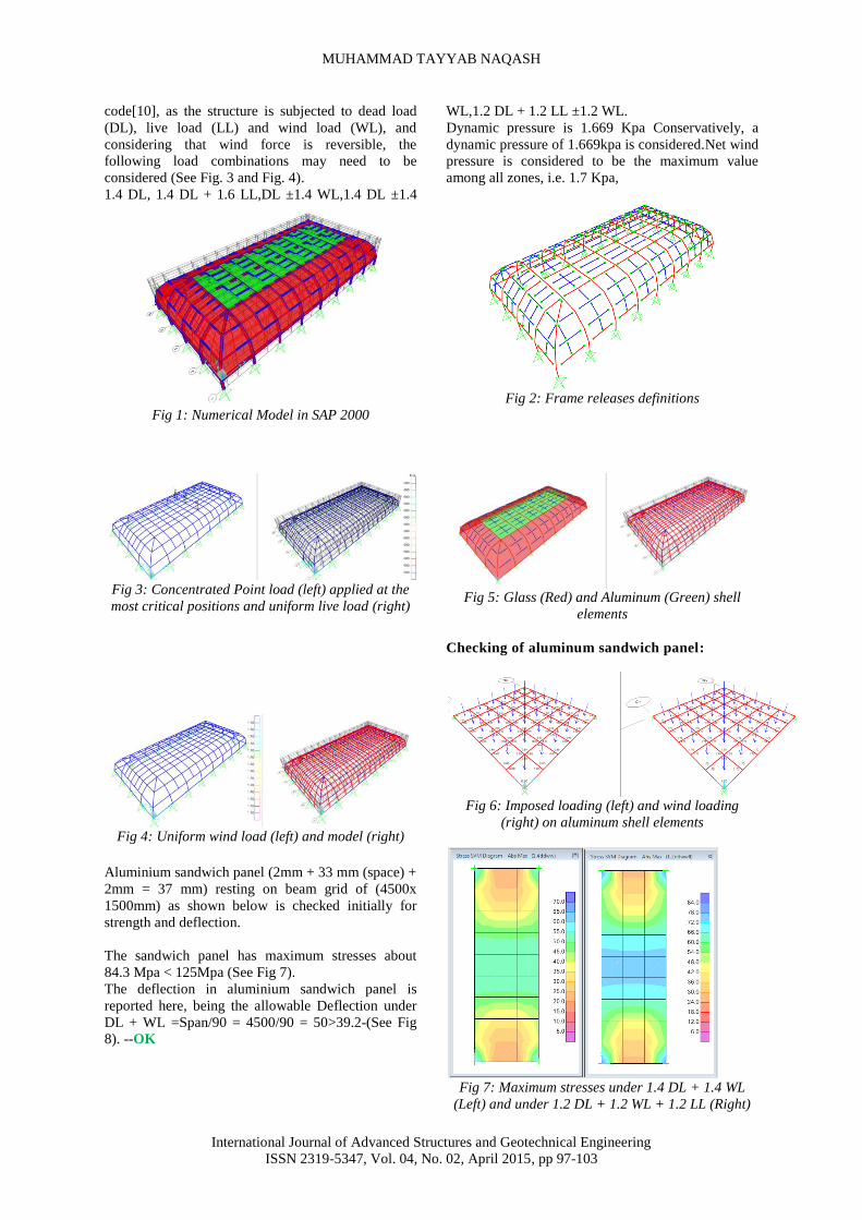
Fig 8a: DL + WL Fig 8b: DL Fig 8c: DL+LL
Allowable Deflection under DL =Span/500 =
4500/500 = 9mm >2.24mm ----OK
Allowable Deflection under DL + LL =Span/200 =
4500/200 = 22.5mm >15.4mm ----OK
The Aluminium Sandwich panels are Safe for both
ultimate limit states and serviceability limit states
Checking of glass panel for strength and
deflection:
The glass panel (13.52mm + 16mm(space) + 8mm =
21.52mm) resting on beam grid of (1500x1500mm)
as shown in Fig 9 is checked initially for strength and
deflection. Conservatively, it is assumed to be
without the air gap and furthermore, it is considered
to be flat although in real situation it is curved,
therefore in real scenario will have reduced stresses
due to membrane action as well deflection.The glass
has maximum stresses of about 38.4 Mpa < 50 Mpa
(See Fig 10) -Hence Safe Allowable Deflection under
any the adopted load combination equals Span/60 =
2250/60 =37.5 mm >23.8 mm (See Fig 11)
The design is carried out taking into account all the
loading combinations and the Demand to Capacity
ratios has been checked, as shown below.
Fig 9: Imposed loading (left) and wind loading
(right) on glass shell elements
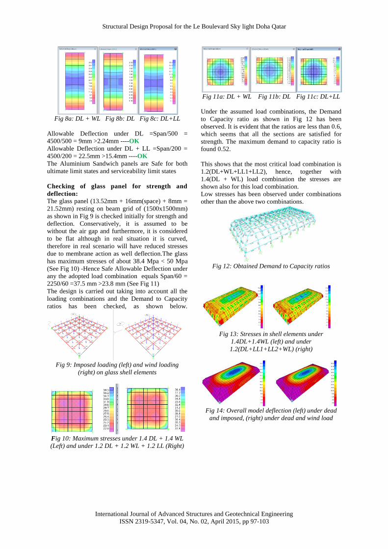
Fig 10: Maximum stresses under 1.4 DL + 1.4 WL
(Left) and under 1.2 DL + 1.2 WL + 1.2 LL (Right)
Fig 11a: DL + WL Fig 11b: DL Fig 11c: DL+LL
Under the assumed load combinations, the Demand
to Capacity ratio as shown in Fig 12 has been
observed. It is evident that the ratios are less than 0.6,
which seems that all the sections are satisfied for
strength. The maximum demand to capacity ratio is
found 0.52.
This shows that the most critical load combination is
1.2(DL+WL+LL1+LL2), hence, together with
1.4(DL + WL) load combination the stresses are
shown also for this load combination.
Low stresses has been observed under combinations
other than the above two combinations.
Fig 12: Obtained Demand to Capacity ratios
Fig 13: Stresses in shell elements under
1.4DL+1.4WL (left) and under
1.2(DL+LL1+LL2+WL) (right)
Fig 14: Overall model deflection (left) under dead
and imposed, (right) under dead and wind load
MUHAMMAD TAYYAB NAQASH
International Journal of Advanced Structures and Geotechnical Engineering
ISSN 2319-5347, Vol. 04, No. 02, April 2015, pp 97-103
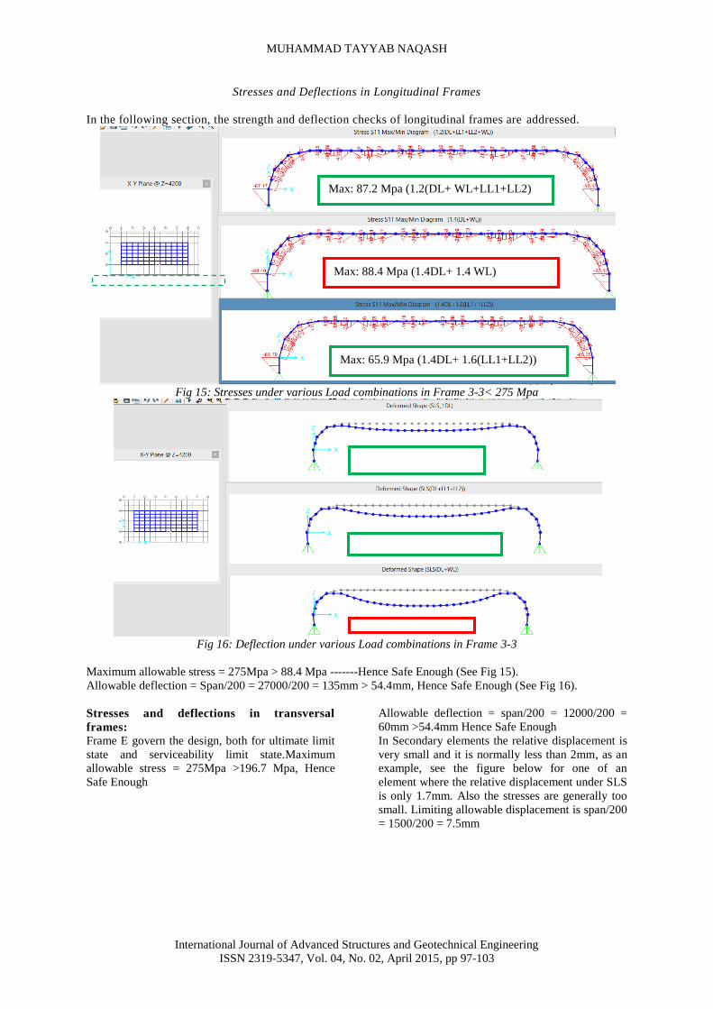
Stresses and Deflections in Longitudinal Frames
In the following section, the strength and deflection checks of longitudinal frames are addressed.
Fig 15: Stresses under various Load combinations in Frame 3-3< 275 Mpa
Fig 16: Deflection under various Load combinations in Frame 3-3
Maximum allowable stress = 275Mpa > 88.4 Mpa -------Hence Safe Enough (See Fig 15).
Allowable deflection = Span/200 = 27000/200 = 135mm > 54.4mm, Hence Safe Enough (See Fig 16).
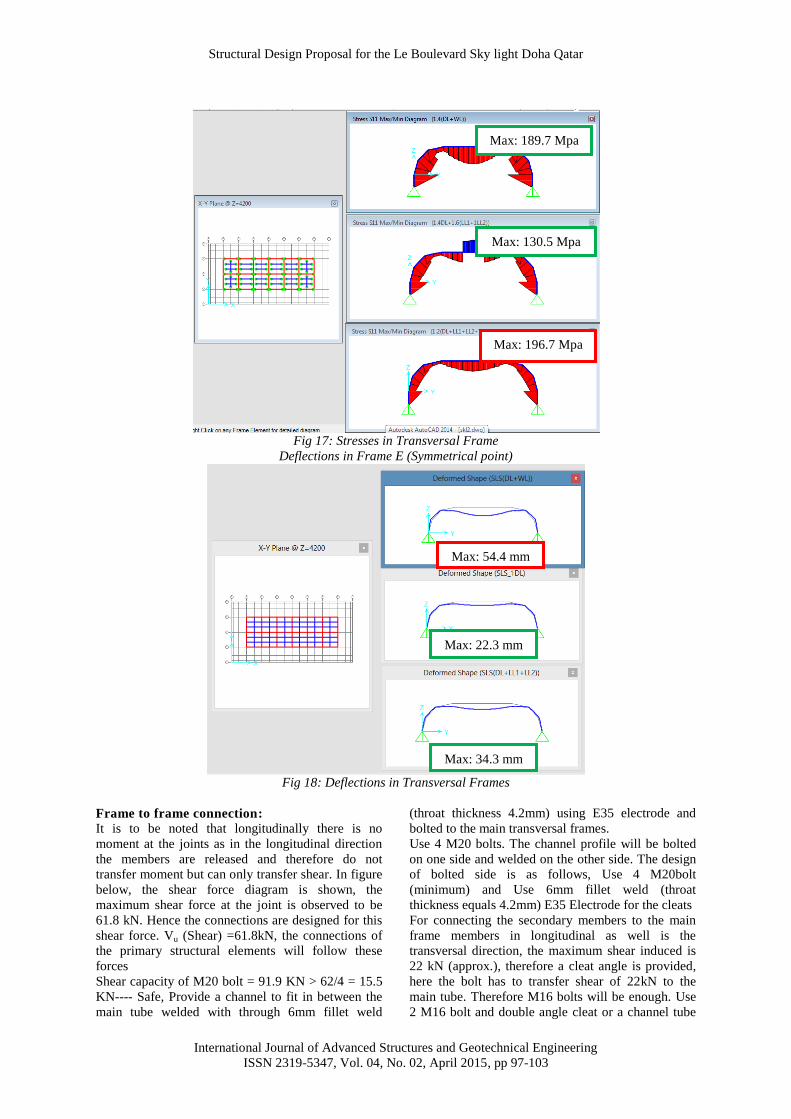
Stresses and deflections in transversal
frames:
Frame E govern the design, both for ultimate limit
state and serviceability limit state.Maximum
allowable stress = 275Mpa >196.7 Mpa, Hence
Safe Enough
Allowable deflection = span/200 = 12000/200 =
60mm >54.4mm Hence Safe Enough
In Secondary elements the relative displacement is
very small and it is normally less than 2mm, as an
example, see the figure below for one of an
element where the relative displacement under SLS
is only 1.7mm. Also the stresses are generally too
small. Limiting allowable displacement is span/200
= 1500/200 = 7.5mm
Max: 65.9 Mpa (1.4DL+ 1.6(LL1+LL2))
Max: 88.4 Mpa (1.4DL+ 1.4 WL)
Max: 87.2 Mpa (1.2(DL+ WL+LL1+LL2)
Max: 54.4 mm (DL+
WL)
Max: 34.3 mm (DL+
LL1+LL2)
Max: 22.3 mm (DL)
Structural Design Proposal for the Le Boulevard Sky light Doha Qatar
International Journal of Advanced Structures and Geotechnical Engineering
ISSN 2319-5347, Vol. 04, No. 02, April 2015, pp 97-103
Fig 17: Stresses in Transversal Frame
Deflections in Frame E (Symmetrical point)
Fig 18: Deflections in Transversal Frames
Frame to frame connection:
It is to be noted that longitudinally there is no
moment at the joints as in the longitudinal direction
the members are released and therefore do not
transfer moment but can only transfer shear. In figure
below, the shear force diagram is shown, the
maximum shear force at the joint is observed to be
61.8 kN. Hence the connections are designed for this
shear force. Vu (Shear) =61.8kN, the connections of
the primary structural elements will follow these
forces
Shear capacity of M20 bolt = 91.9 KN > 62/4 = 15.5
KN---- Safe, Provide a channel to fit in between the
main tube welded with through 6mm fillet weld
(throat thickness 4.2mm) using E35 electrode and
bolted to the main transversal frames.
Use 4 M20 bolts. The channel profile will be bolted
on one side and welded on the other side. The design
of bolted side is as follows, Use 4 M20bolt
(minimum) and Use 6mm fillet weld (throat
thickness equals 4.2mm) E35 Electrode for the cleats
For connecting the secondary members to the main
frame members in longitudinal as well is the
transversal direction, the maximum shear induced is
22 kN (approx.), therefore a cleat angle is provided,
here the bolt has to transfer shear of 22kN to the
main tube. Therefore M16 bolts will be enough. Use
2 M16 bolt and double angle cleat or a channel tube
Max: 196.7 Mpa
Max: 130.5 Mpa
Max: 189.7 Mpa
Max: 54.4 mm
Max: 22.3 mm
Max: 34.3 mm

MUHAMMAD TAYYAB NAQASH
International Journal of Advanced Structures and Geotechnical Engineering
ISSN 2319-5347, Vol. 04, No. 02, April 2015, pp 97-103
80x80x8.From the above results, The Bracket is
subjected to the following, Maximum reactions due
to Ultimate limit state V= 22KN, Assume Stainless
Steel M16 bolts and therefore it is found safe.
Sleeve connection:
Since it is difficult to transport the transversal frame
as one member, therefore, sleeve connections are
made. These connections are located at a distance of
750mm from the joint where the curve member
meets. The maximum shear at this point is about
41kN, a bending moment of 73 KN-m is recorded.
The proposed connection is as shown below, Since
six bolts are considered on one side, Axial Tension /
Compression due to bending moment on group of
bolts is 73/0.3 = 243 KN, Vertical shear = 41 KN,
Therefore, net axial shear in bolts will be 243 + 41 =
284 KN, Shear capacity of M20 grade 8.8 bolts = 71
KN, Bolts required = 284/71 = 3.9 Say 6 bolts (for
safety allowance) Use 6 M20 bolts (minimum)
Fig 19: Longitudinal frame to the Transversal frame
connection
Fig 20: Detail of Sleeve Connection
Fig 21: Isometric view of Sleeve Connection
Fig 22: Structural Section of the Skylight
Checking the connection for shear,
Shear area of the sleeve (220 x 170 x 12) = 220 x 12
x 2 = 5280mm2
Pv = 0.6 Py Av = 0.6 (275) (2x 200x)12/1000 =
792KN >284 KN -----OK
Maximum reactions under 1.4 (DL + WL) are Fx =
22 KN (Shear), Fy = 108 KN (Shear) and Fz = 182
KN (Vertical compression), whereas Maximum
reactionsunder 1.2 (DL + WL+ LL1+ LL2)are Fx =
23 KN (Shear), Fy = 112 KN (Shear) and Fz = 187.7
KN (Vertical compression)
Provide 6mm fillet weld (throat thickness 4.2mm) all
around the tube,Perimeter of the weld will be 250x2
+ 200x 2 = 900mm and Area of weld is 900x4.2 =
3780 mm2
Maximum Fx = 23 KN (Shear), Fy = 112 KN (Shear)
and Fz = 187.7 KN (Vertical compression), Resultant
shear is 114KN and therefore the stresses in weld
were found to be 30 Mpa < 220 Mpa, hence 6mm
fillet weld (throat thickness 4.2mm) of E35 Electrode
around the tube is recommended.
The base plate dimensions are calculatedas per
British Standards and found that using 400 x 300 x
20 (mm), thick steel base plate with s275 (yield
strength 275 Mpa) is safe enough. The HIT-HY 200
M16or any equivalent anchors bolts are
recommended being conservatively with the
assumption of Cracked Concrete [14] with very wide
reinforcement. The ancher bolts are designed for the
following loads,Maximum Fx = 23 KN (Shear), Fy =
112 KN (Shear) and Fz = 187.7 KN (Vertical
compression).
Hilti SAFEset HIT-Z anchor with HIT-HY 200
injection mortar with 96 mm embedment h_ef, M16,
Steel galvanized, Hammer drilled installation per
ETA 12/0028 or any other equivalent anchors are
recommended.
Conclusions:
Aluminium metal sandwich panels having 2mm top
and bottom thickness with 33 mm insulating material
is Safe both for Ultimate Limit States and
Serviceability Limit States and therefore shall be
used as minimum. Fully tempered glass of 21.52mm
thickness is Safe both for Ultimate Limit States and
Serviceability Limit States and therefore shall be
used as minimum 150 x 150 x 10 Hollow steel tube
of S275 steel grade for the supporting structure for
transferring loads to the main frame is Safe both for
Ultimate Limit States and Serviceability Limit States
and therefore shall be used as minimum

Structural Design Proposal for the Le Boulevard Sky light Doha Qatar
International Journal of Advanced Structures and Geotechnical Engineering
ISSN 2319-5347, Vol. 04, No. 02, April 2015, pp 97-103
250 x 200 x 12 hollow steel tube of S275 steel grade
for the main structure for transferring loads to the
base plate is Safe both for Ultimate Limit States and
Serviceability Limit States and shall be used as
minimum
M16 bolt of grade 8.8 and cleat angle or a channel
tube 80x80x8 (minimum)mild steel of S275 steel
grade on one side and 6mm fillet weld (throat
thickness 4.2mm) on the other side of cleat for
connecting the secondary members shall be used as
minimum
M20 bolt of grade 8.8with a channel of mild steel of
S275 steel grade on one side and 6mm fillet weld
(throat thickness 4.2mm) on the other side for
connecting the longitudinal frame with the
transversal frame shall be used as minimum
M20bolt of grade 8.8 shall be used for the sleeve
connection
M16 stainless steel bolt class 80 shall be used as
minimum for bracket connection
400 x 300 x 20 mm thick base plate of S275 steel
grade shall be used
Hilti SAFEset 4 numbers of HIT-Z anchor with HIT-
HY 200 injection mortar with 96 mm embedment
h_ef, M16, Steel galvanized, Hammer drilled
installation per ETA 12/0028 shall be used as
minimum
Acknowledgement:
The Author acknowledged the support of his
employer ALUTEC W.L.L, Qatar’s largest
Aluminium and glazing company, specializing in
architectural Aluminium and glass products,
Aluminium doors, windows, skylights, cladding
projects and unitized as well in standard curtain walls
systems.
References:
[1] BS 6399-2, Loading for buildings, Part 2: Code
of practice for wind loads. British Standard,
1997
[2] QCS 2014-2010, Qatar Construction
Specifications. 2010, 2014.
[3] Leo Chan, Structural Use of Glass in Buildings.
The Institute of Structural Engineers, 1999.
[4] prEN 13474-2, Glass in building- Design of
glass panes-Part 2: Design for uniformly
distributed loads. European Standard, 2000.
[5] prEN 13474-3, Glass in building -
Determination of the strength of glass panes -
Part 3: General method of calculation and
determination of strength of glass by testing.
European Standard, 2009.
[6] CSI SAP V15, Integrated Finite Element
Analysis and Design of Structures Basic
Analysis Reference Manual. Computers and
Structures, Inc., Berkeley, CA, USA, 2002.
[7] AS 1288, Glass in Buildings: Selection and
Installation. Australian Standard, 2006.
[8] BS 8188-1, Structural use of aluminium, Part 1:
Code of Practice for Design. British Standard,
1991.
[9] BS 8188-2, Structural use of aluminium, Part 2:
Specification for materials, workmanship and
protection. British Standard, 1991.
[10] BS 5950-1, Structural use of steelwork in
building. British Standard, 2000.
[11] BS 5950-2, Specification for materials,
fabrication and erection — Rolled and welded
sections. British Standard, 2001.
[12] BS 5427-1, The use of profiles sheet for roof
and wall cladding on buildings. British
Standard, 1996.
[13] BS 6399-3, Loading for buildings, Part 3: Code
of practice for imposed roof loads. British
Standard, 1988.
[14] HILTI PROFIS 2.4.7, Hilti PROFIS Anchor
software Hilti registered trademark of Hilti
Corporation, 9494 Schaan, Liechtenstein 2009-
2011.