Structural Design for Pressure- And Temperature- Resistant ...
19
Article Structural Design for Pressure- And Temperature- Resistant Buildings Boonchai Sonthirongnachai a and Arthit Petchsasithon b,* Department of Civil Engineering, Faculty of Engineering, King Mongkut’s Institute of Technology Ladkrabang, Bangkok 10520, Thailand E-mail: a [email protected], b [email protected] (Corresponding author) Abstract. Loads from explosions differ from seismic and wind loads due to their greater severity, continuity, rapidity, and thermal extremity. That is, explosions cause massive structural damage by exposing surrounding structures to extremely high pressure and temperature. Thus, structures at risk of explosive damage must be stronger than typical buildings in withstanding both ordinary loads and the additional pressure and temperature loads caused. Explosion-resistant structures are required in the petrochemical industry, explosive armories, power stations, and gas storage facilities, among others. This study aims to examine the structural performance of a building subject to three types of loads: (1) the pressure of 300 bars, (2) the temperature of 300 C, and (3) the pressure of 300 bars combined with the temperature of 300 C. The research analyzes three primary reinforced structures, namely columns, beams, and slabs, in terms of the parameters resulting from each scenario to determine a set of criteria for designing the structural components of explosion-resistant buildings. Keywords: Pressure load, temperature load, pressure- and temperature-resistant buildings. ENGINEERING JOURNAL Volume 23 Issue 3 Received 12 September 2018 Accepted 19 March 2019 Published 31 May 2019 Online at http://www.engj.org/ DOI:10.4186/ej.2019.23.3.75
Transcript of Structural Design for Pressure- And Temperature- Resistant ...

Article
Structural Design for Pressure- And Temperature-Resistant Buildings Boonchai Sonthirongnachaia and Arthit Petchsasithonb,*
Department of Civil Engineering, Faculty of Engineering, King Mongkut’s Institute of Technology Ladkrabang, Bangkok 10520, Thailand E-mail: [email protected], [email protected] (Corresponding author) Abstract. Loads from explosions differ from seismic and wind loads due to their greater severity, continuity, rapidity, and thermal extremity. That is, explosions cause massive structural damage by exposing surrounding structures to extremely high pressure and temperature. Thus, structures at risk of explosive damage must be stronger than typical buildings in withstanding both ordinary loads and the additional pressure and temperature loads caused. Explosion-resistant structures are required in the petrochemical industry, explosive armories, power stations, and gas storage facilities, among others. This study aims to examine the structural performance of a building subject to three types of loads: (1) the
pressure of 300 bars, (2) the temperature of 300 C, and (3) the pressure of 300 bars
combined with the temperature of 300 C. The research analyzes three primary reinforced structures, namely columns, beams, and slabs, in terms of the parameters resulting from each scenario to determine a set of criteria for designing the structural components of explosion-resistant buildings. Keywords: Pressure load, temperature load, pressure- and temperature-resistant buildings.
ENGINEERING JOURNAL Volume 23 Issue 3 Received 12 September 2018 Accepted 19 March 2019 Published 31 May 2019 Online at http://www.engj.org/ DOI:10.4186/ej.2019.23.3.75
DOI:10.4186/ej.2019.23.3.75
76 ENGINEERING JOURNAL Volume 23 Issue 3, ISSN 0125-8281 (http://www.engj.org/)
1. Introduction Designing residential buildings in Thailand generally involves the utilization of space and aesthetics as well as fulfilment of the standards and requirements stipulated in the 2522 B.E. Building Control Act. However, some structures at risk of explosions, such as buildings in the petrochemical industry [1], explosive armories [2], power stations [3-4], gas storage facilities [1, 5], and energy research centres [6], must also be designed to resist the additional loads resulting from explosive pressure [7] and temperature [8], to prevent collapse, and ultimately to safeguard life and property. To this end, their design must account for not only dead loads (DLs) [9-12] and live loads (LLs) [9-12], but also blast load (BLs) [13]. Since BLs [13] consist of pressure loads, temperature loads, and combined pressure and temperature loads, they are more severe and occur in exponentially smaller time-windows than either seismic or seasonal wind loads [14-15].
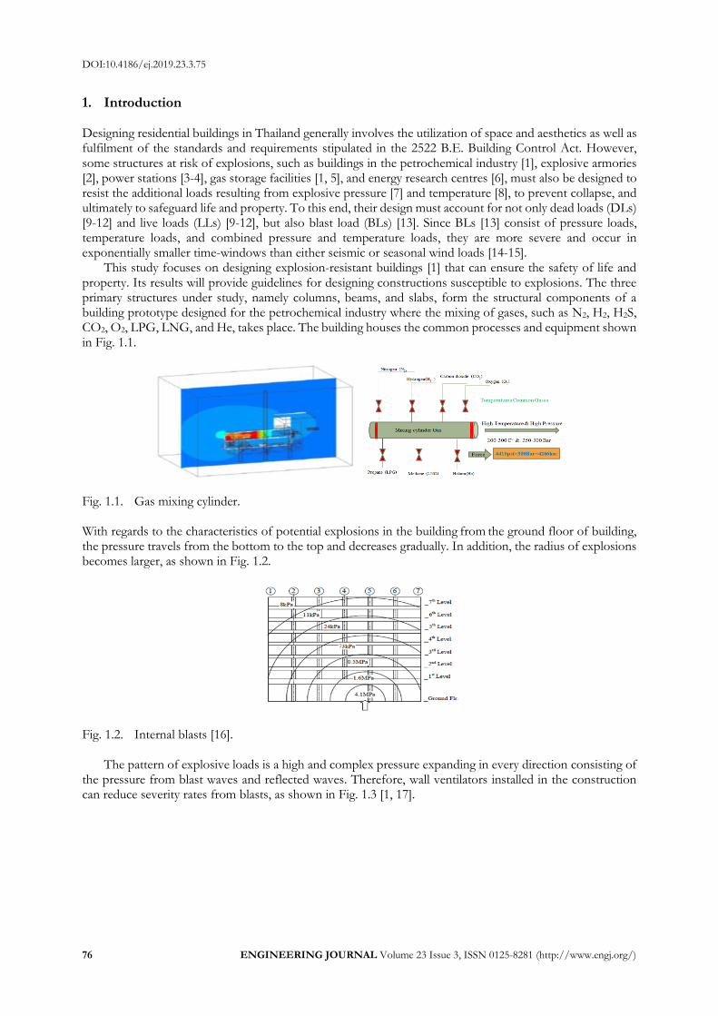
This study focuses on designing explosion-resistant buildings [1] that can ensure the safety of life and property. Its results will provide guidelines for designing constructions susceptible to explosions. The three primary structures under study, namely columns, beams, and slabs, form the structural components of a building prototype designed for the petrochemical industry where the mixing of gases, such as N2, H2, H2S, CO2, O2, LPG, LNG, and He, takes place. The building houses the common processes and equipment shown in Fig. 1.1.
Fig. 1.1. Gas mixing cylinder. With regards to the characteristics of potential explosions in the building from the ground floor of building, the pressure travels from the bottom to the top and decreases gradually. In addition, the radius of explosions becomes larger, as shown in Fig. 1.2.
Fig. 1.2. Internal blasts [16].
The pattern of explosive loads is a high and complex pressure expanding in every direction consisting of the pressure from blast waves and reflected waves. Therefore, wall ventilators installed in the construction can reduce severity rates from blasts, as shown in Fig. 1.3 [1, 17].

DOI:10.4186/ej.2019.23.3.75
ENGINEERING JOURNAL Volume 23 Issue 3, ISSN 0125-8281 (http://www.engj.org/) 77
Fig. 1.3. Effects of ventilators on internal blasts [1].
Outside of the building sits the equipment used for gas storage and high-pressure control, as shown in Fig. 1.4. This area is designated as a hazardous or safety alert zone [18].
Fig. 1.4. Equipment installed outside the building.
Explosive severity depends on the distance from the sources of blasts, as shown in Fig. 1.5 [5, 19].
Fig. 1.5. Externals blasts [5].
Figure 1.5 shows the characteristics of external blasts and pressure wave expansion. To determine the
scaled distance (𝑍), the following equation is used [16]: R is the actual effective distance from the explosion. W is generally expressed in kilograms. Scaling laws provide parametric correlations between a particular explosion and a standard charge of the same substance
𝑍 = 𝑅 𝑊1
3⁄⁄ (1)
𝑍 > 10 𝐹𝑎𝑟 𝐹𝑖𝑒𝑙𝑑 𝐵𝑙𝑎𝑠𝑡 3 < 𝑍 < 10 𝑁𝑒𝑎𝑟 𝐹𝑖𝑙𝑑 𝐵𝑙𝑎𝑠𝑡 𝑍 < 3 𝐶𝑙𝑜𝑠𝑒 − 𝑖𝑛 𝐵𝑙𝑎𝑠𝑡 𝑊 = 𝑀𝑎𝑠𝑠 𝑜𝑓 𝑡ℎ𝑒 𝑒𝑥𝑝𝑙𝑜𝑠𝑖𝑜𝑛 𝑅 = 𝐷𝑖𝑠𝑡𝑎𝑛𝑐𝑒 𝑓𝑟𝑜𝑚 𝑡ℎ𝑒 𝑑𝑒𝑡𝑜𝑛𝑎𝑡𝑖𝑜𝑛 𝑠𝑜𝑢𝑟𝑐𝑒
For extensive charts for predicting blast pressures and blast durations Ratio of explosive mass to distance from the detonation source as shown in Table 1.1.

DOI:10.4186/ej.2019.23.3.75
78 ENGINEERING JOURNAL Volume 23 Issue 3, ISSN 0125-8281 (http://www.engj.org/)
Table 1.1. Ratio of explosive mass to distance from the detonation source [16].
100 kg TNT
500 kg TNT
1000 kg TNT
2000 kg TNT
1m 165.8 354.5 464.5 602.9 2.5m 34.2 89.4 130.8 188.4 5 m 6.65 24.8 39.5 60.19 10m 0.85 4.25 8.15 14.7 15m 0.27 1.25 2.53 5.01 20m 0.14 0.54 1.06 2.13 25m 0.09 0.29 0.55 1.08 30m 0.06 0.19 0.33 0.63
The pressure caused by explosions will flow up through the atmosphere until reaching a peak , referred
to as the positive phase, and will then flow back through the atmosphere to the point underneath it ,
referred to as the negative phase, as shown in Fig. 1.6 [1]. This cycle will repeat until there is no pressure left.
Fig. 1.6. Relationships between explosive duration and pressure [1, 20].
𝐼0 = ∫ 𝑃(𝑡)𝑑𝑡𝑡𝑑
0 (2)
= 0.5𝑃𝑠𝑜𝑡𝑑 , 𝑓𝑜𝑟 𝑎 𝑡𝑟𝑖𝑎𝑛𝑔𝑢𝑙𝑎𝑟 𝑤𝑎𝑣𝑒
= 0.64𝑃𝑠𝑜𝑡𝑑 , 𝑓𝑜𝑟 𝑎 ℎ𝑎𝑙𝑓 − 𝑠𝑖𝑛𝑒 𝑤𝑎𝑣𝑒
= 𝑐𝑃𝑠𝑜𝑡𝑑 , 𝑓𝑜𝑟 𝑎𝑛 𝑒𝑥𝑝𝑜𝑛𝑒𝑛𝑡𝑖𝑎𝑙𝑙𝑦 𝑑𝑒𝑐𝑎𝑦𝑖𝑛𝑔 𝑠ℎ𝑜𝑐𝑘 𝑤𝑎𝑣𝑒 where:
𝐼0 = 𝑃ℎ𝑎𝑠𝑒 𝐼𝑚𝑝𝑢𝑙𝑠𝑒
𝑃(𝑡) = 𝑂𝑣𝑒𝑟𝑝𝑟𝑒𝑠𝑠𝑢𝑟𝑒 𝑓𝑢𝑛𝑐𝑡𝑖𝑜𝑛 𝑤𝑖𝑡ℎ 𝑟𝑒𝑠𝑝𝑒𝑐𝑡 𝑡𝑜 𝑡𝑖𝑚𝑒
𝑃𝑠𝑜 = 𝑃𝑒𝑎𝑘, 𝑜𝑟 𝑖𝑛𝑐𝑖𝑑𝑒𝑛𝑡, 𝑠𝑖𝑑𝑒 − 𝑜𝑛 𝑜𝑣𝑒𝑟𝑝𝑟𝑒𝑠𝑠𝑢𝑟𝑒
𝑡𝑑 = 𝐷𝑢𝑟𝑎𝑡𝑖𝑜𝑛 𝑜𝑓 𝑡ℎ𝑒 𝑝𝑜𝑠𝑖𝑡𝑖𝑣𝑒 𝑝ℎ𝑎𝑠𝑒
𝑐 = 𝐴 𝑣𝑎𝑙𝑢𝑒 𝑏𝑒𝑡𝑤𝑒𝑒𝑛 0.2 𝑎𝑛𝑑 0.5 𝑑𝑒𝑝𝑒𝑛𝑑𝑖𝑛𝑔 𝑜𝑛 𝑃𝑠𝑜
Fig. 1.7. Relationships between the negative phase and vibration waves [1, 20].
soP
soP
R
W W

DOI:10.4186/ej.2019.23.3.75
ENGINEERING JOURNAL Volume 23 Issue 3, ISSN 0125-8281 (http://www.engj.org/) 79
Before the negative phase, the pressure increases, and the compressed air causes a shockwave. During this period, the pressure is a dynamic waveform expanding in a circular pattern. The wave characterizing an explosion is referred to as a shock load, which is a vibration wave [20].
Since fuel is a high-temperature hydrocarbon affecting the strength requirements of a building, the structural components of the construction need to be considered in conjunction with the temperature generated from the combustion of a blast. The thermal resistance characteristics of steel and concrete are
shown in Table 1.2. Table 1.2. Comparison of the strength of concrete and steel.
Properties Mild Steel Concrete
Mass per unit kg (m3) 7850 2400 Elastic modulus (ksc) 2100000 200000 Thermal resistance (C) 250-550 300-600
Lifespan (y) 10-20 30-50 Compressive strength (ksc) 3500-5000 200-500 Tensile strength (ksc) 3500-5000 0-50
Table 1.2 shows that steel is less resistant to heat than concrete, whereas concrete is less resistant to strain
than steel. The relationships between temperature and steel strength are shown in Fig. 1.8 [21].
Fig. 1.8. Relationships between temperature and steel strength [21].
For concrete, a rise in temperature will decrease its strength, as shown in Fig. 1.9. As the temperature rises, concrete will expand, which in turn increases its strain percentage and lowers its strength, causing the material to collapse [21].
Fig. 1.9. Relationships between temperature and strain percentage [21].
2. Designing a Building That Can Resist the Pressure Load of 300 Bars Figure 2.1 shows a model of the test building, whose dimensions are 40.00 m x 30.00 m x 22.00 m.

DOI:10.4186/ej.2019.23.3.75
80 ENGINEERING JOURNAL Volume 23 Issue 3, ISSN 0125-8281 (http://www.engj.org/)
Fig. 2.1. Model of the pressure-resistant building.
The specifications of the building designed to resist the pressure load of 300 bars include the dimensions of rooms and details of the building components with the columns, beams, and slabs being the primary structural components affected by the pressure loads, as shown in Fig. 2.1.
Fig. 2.2. Floor plan of the test building.
As shown in Fig. 2.2, four rooms were used to test the pressure load of 300 bars. Their dimensions were 8.00 m x 6.00 m x 4.00 m. The pressure load not only affected all the rooms, as shown in Fig. 2.3, but also caused the maximum reaction force and moment to the columns, as shown in Table 2.1. Table 2.1. Maximum reaction force and moment caused to the columns.
Column pressure load of 300 bars
Items Columns
Reaction force (N) 43704296
Reaction moment (N-mm) 7259233280
Fig. 2.3. Pressure load of 300 bars.
DOI:10.4186/ej.2019.23.3.75
ENGINEERING JOURNAL Volume 23 Issue 3, ISSN 0125-8281 (http://www.engj.org/) 81
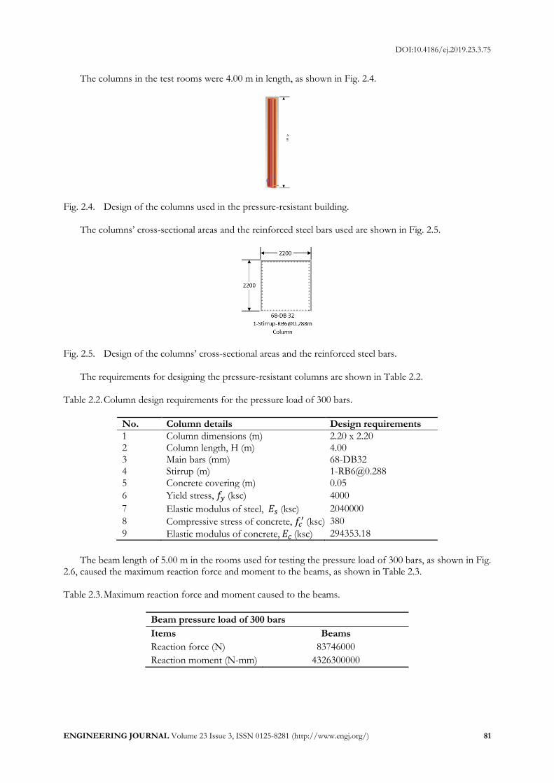
The columns in the test rooms were 4.00 m in length, as shown in Fig. 2.4.
Fig. 2.4. Design of the columns used in the pressure-resistant building.
The columns’ cross-sectional areas and the reinforced steel bars used are shown in Fig. 2.5.
Fig. 2.5. Design of the columns’ cross-sectional areas and the reinforced steel bars.
The requirements for designing the pressure-resistant columns are shown in Table 2.2. Table 2.2. Column design requirements for the pressure load of 300 bars.
No. Column details Design requirements
1 Column dimensions (m) 2.20 x 2.20 2 Column length, H (m) 4.00 3 Main bars (mm) 68-DB32 4 Stirrup (m) [email protected] 5 Concrete covering (m) 0.05
6 Yield stress, 𝑓𝑦 (ksc) 4000
7 Elastic modulus of steel, 𝐸𝑠 (ksc) 2040000
8 Compressive stress of concrete, 𝑓𝑐′ (ksc) 380
9 Elastic modulus of concrete, 𝐸𝑐 (ksc) 294353.18
The beam length of 5.00 m in the rooms used for testing the pressure load of 300 bars, as shown in Fig.
2.6, caused the maximum reaction force and moment to the beams, as shown in Table 2.3. Table 2.3. Maximum reaction force and moment caused to the beams.
Beam pressure load of 300 bars
Items Beams
Reaction force (N) 83746000
Reaction moment (N-mm) 4326300000

DOI:10.4186/ej.2019.23.3.75
82 ENGINEERING JOURNAL Volume 23 Issue 3, ISSN 0125-8281 (http://www.engj.org/)
Fig. 2.6. Design of the beams used in the pressure-resistant building.
The beams’ cross-sectional areas and the reinforced steel bars used are shown in Fig. 2.7.
Fig. 2.7. Designs of the beams’ cross-sectional areas and the reinforced steel bars
The requirements for designing the pressure-resistant beams are shown in Table 2.4. Table 2.4. Beam design requirements for the pressure load of 300 bars.
No. Beam details Design requirements
1 Beam dimensions (m) 1.50 x 2.00 2 Beam length, H (m) 8.00
3 Main bars (mm)
15-DB28,12-DB28,15-DB28,15-DB32 9-DB32,9-DB32,25-DB25,28-DB28
4 Stirrup (cm) [email protected] 5 Concrete covering (m) 0.05
6 Yield stress, 𝑓𝑦 (ksc) 5000
7 Elastic modulus of steel, 𝐸𝑠 (ksc) 2040000
8 Compressive stress of concrete, 𝑓𝑐′ (ksc) 320
9 Elastic modulus of concrete, 𝐸𝑐 (ksc) 270117
The slab dimensions of 8.00 m x 6.00 m in the rooms used for testing the pressure load of 300 bars, as
shown in Fig. 2.8, caused the maximum reaction force and moment to the slabs, as shown in Table 2.5. Table 2.5. Maximum reaction force and moment caused to the slabs.
Slab pressure load of 300 bars
Items Slabs
Reaction force (N) 72967000
Reaction moment (N-mm) 607430000
DOI:10.4186/ej.2019.23.3.75
ENGINEERING JOURNAL Volume 23 Issue 3, ISSN 0125-8281 (http://www.engj.org/) 83
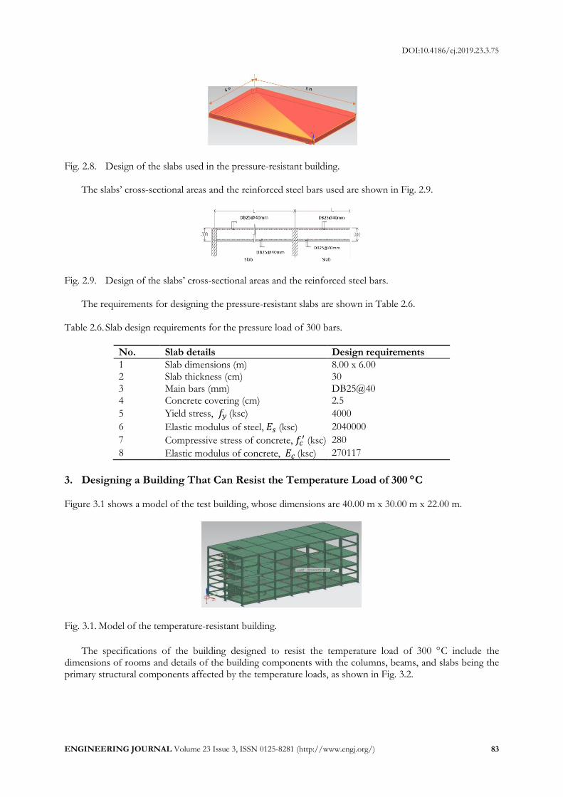
Fig. 2.8. Design of the slabs used in the pressure-resistant building.
The slabs’ cross-sectional areas and the reinforced steel bars used are shown in Fig. 2.9.
Fig. 2.9. Design of the slabs’ cross-sectional areas and the reinforced steel bars.
The requirements for designing the pressure-resistant slabs are shown in Table 2.6. Table 2.6. Slab design requirements for the pressure load of 300 bars.
No. Slab details Design requirements
1 Slab dimensions (m) 8.00 x 6.00 2 Slab thickness (cm) 30
3 Main bars (mm) DB25@40 4 Concrete covering (cm) 2.5
5 Yield stress, 𝑓𝑦 (ksc) 4000
6 Elastic modulus of steel, 𝐸𝑠 (ksc) 2040000
7 Compressive stress of concrete, 𝑓𝑐′ (ksc) 280
8 Elastic modulus of concrete, 𝐸𝑐 (ksc) 270117
3. Designing a Building That Can Resist the Temperature Load of 300 C Figure 3.1 shows a model of the test building, whose dimensions are 40.00 m x 30.00 m x 22.00 m.
Fig. 3.1. Model of the temperature-resistant building.
The specifications of the building designed to resist the temperature load of 300 C include the dimensions of rooms and details of the building components with the columns, beams, and slabs being the primary structural components affected by the temperature loads, as shown in Fig. 3.2.

DOI:10.4186/ej.2019.23.3.75
84 ENGINEERING JOURNAL Volume 23 Issue 3, ISSN 0125-8281 (http://www.engj.org/)
Fig. 3.2. Floor plan of the test building.
As shown in Fig. 3.2, four rooms were used to test the temperature load of 300 C. Their dimensions were 8.00 m x 6.00 m x 4.00 m. The temperature was controlled at a constant level throughout the building. The temperature load not only affected all the rooms and caused a temperature rise throughout the building, as shown in Fig. 3.3, but also caused the maximum reaction force and moment to the columns, as shown in Table 3.1. Table 3.1. Maximum reaction force and moment caused to the columns.
Column temperature load of 300 C
Items Columns Reaction force (N) 2431292.75 Reaction moment (N-mm) 18412986
Fig. 3.3. Temperature load of 300 C.
The columns in the test rooms were 4.00 m in length, as shown in Fig. 3.4.
Fig. 3.4. Design of the columns used in the temperature-resistant building.
The columns’ cross-sectional areas and the reinforced steel bars used are shown in Fig. 3.5.
Fig. 3.5. Design of the columns’ cross-sectional areas and the reinforced steel bars.
DOI:10.4186/ej.2019.23.3.75
ENGINEERING JOURNAL Volume 23 Issue 3, ISSN 0125-8281 (http://www.engj.org/) 85
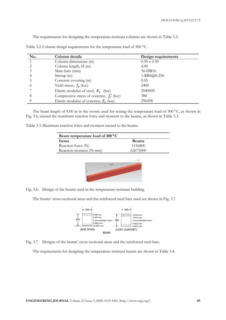
The requirements for designing the temperature-resistant columns are shown in Table 3.2.
Table 3.2. Column design requirements for the temperature load of 300 C.
No. Column details Design requirements
1 Column dimensions (m) 0.50 x 0.50 2 Column length, H (m) 4.00 3 Main bars (mm) 36-DB16 4 Stirrup (m) [email protected] 5 Concrete covering (m) 0.05
6 Yield stress, 𝑓𝑦 (ksc) 2400
7 Elastic modulus of steel, 𝐸𝑠 (ksc) 2040000
8 Compressive stress of concrete, 𝑓𝑐′ (ksc) 380
9 Elastic modulus of concrete, 𝐸𝑐 (ksc) 296498
The beam length of 8.00 m in the rooms used for testing the temperature load of 300 C, as shown in Fig. 3.6, caused the maximum reaction force and moment to the beams, as shown in Table 3.3. Table 3.3. Maximum reaction force and moment caused to the beams.
Beam temperature load of 300 C
Items Beams Reaction force (N) 1156800 Reaction moment (N-mm) 62675000
Fig. 3.6. Design of the beams used in the temperature-resistant building.
The beams’ cross-sectional areas and the reinforced steel bars used are shown in Fig. 3.7.
Fig. 3.7. Designs of the beams’ cross-sectional areas and the reinforced steel bars.
The requirements for designing the temperature-resistant beams are shown in Table 3.4.

DOI:10.4186/ej.2019.23.3.75
86 ENGINEERING JOURNAL Volume 23 Issue 3, ISSN 0125-8281 (http://www.engj.org/)
Table 3.4. Beam design requirements for the temperature load of 300 C.
No. Beam details Design requirements
1 Beam dimensions (m) 0.30 x 0.30 2 Beam length, H (m) 8.00
3 Main bars (mm)
6-DB9,6-DB9, 6-DB12,16-DB12 9-DB16,9-DB12, 6-DB9,6-DB9
4 Stirrup (cm) [email protected] 5 Concrete covering (m) 0.05
6 Yield stress, 𝑓𝑦 (ksc) 2400
7 Elastic modulus of steel, 𝐸𝑠 (ksc) 2040000
8 Compressive stress of concrete, 𝑓𝑐′ (ksc) 320
9 Elastic modulus of concrete, 𝐸𝑐 (ksc) 272085
The slab dimensions of 8.00 m x 6.00 m in the rooms for testing the temperature load of 300 C, as
shown in Fig. 3.8, caused the maximum reaction force and moment to the slabs, as shown in Table 3.5. Table 3.5. Maximum reaction force and moment caused to the slabs.
Slab temperature loads at 300 C
Items Slabs Reaction force (N) 465620
Reaction moment (N-mm) 62675000
Fig. 3.8. Design of the slabs used in the temperature-resistant building.
The slabs’ cross-sectional areas and the reinforced steel bars used are shown in Fig. 3.9.
Fig. 3.9. Design of the slabs’ cross-sectional areas and the reinforced steel bars.
The requirements for designing the temperature-resistant slabs are shown in Table 3.6.

DOI:10.4186/ej.2019.23.3.75
ENGINEERING JOURNAL Volume 23 Issue 3, ISSN 0125-8281 (http://www.engj.org/) 87
Table 3.6. Slab design requirements for the temperature load of 300 C.
No. Slab details Design requirements
1 Slab dimensions (m) 8.00 x 6.00 2 Slab thickness (cm) 25.00 3 Main Bars (mm) DB25@30 4 Concrete covering (cm) 0.05 5 Yield stress, (ksc) 2400 6 Elastic modulus of steel, (ksc) 2040000 7 Compressive stress of concrete, (ksc) 240 8 Elastic modulus of concrete, (ksc) 235632
4. Designing a Building That Can Resist the Pressure Load of 300 Bars and the
Temperature Load of 300 C Figure 4.1 shows a model of the pressure- and temperature-resistant building, whose dimensions are 40.00 m x 30.00 m x 22.00 m.
Fig. 4.1. Model of the pressure- and temperature-resistant building.
The specifications of the test building designed to resist the pressure load of 300 bars and the temperature
load of 300 C include the dimensions of rooms and details of the building components with the columns, beams, and slabs being the primary structural components affected by the pressure and temperature loads, as shown in Fig. 4.2.
Fig. 4.2. Floor plan of the building exposed to pressure and thermal loads.
As shown in Fig. 4.2, four rooms were used to test the pressure load of 300 bars and the temperature
load of 300 C. Their dimensions were 8.00 m x 6.00 m x 4.00 m. The combined pressure and temperature loads not only affected all the rooms, as shown in Fig. 4.3, but also caused the maximum reaction force and moment to the columns, as shown in Table 4.1. Table 4.1. Maximum reaction force and moment caused to the columns.
Combined column pressure load of 300 bars and temperature load of 300 C
Items Columns Reaction force (N) 46135588.75 Reaction moment (N-mm) 7277646266
DOI:10.4186/ej.2019.23.3.75
88 ENGINEERING JOURNAL Volume 23 Issue 3, ISSN 0125-8281 (http://www.engj.org/)
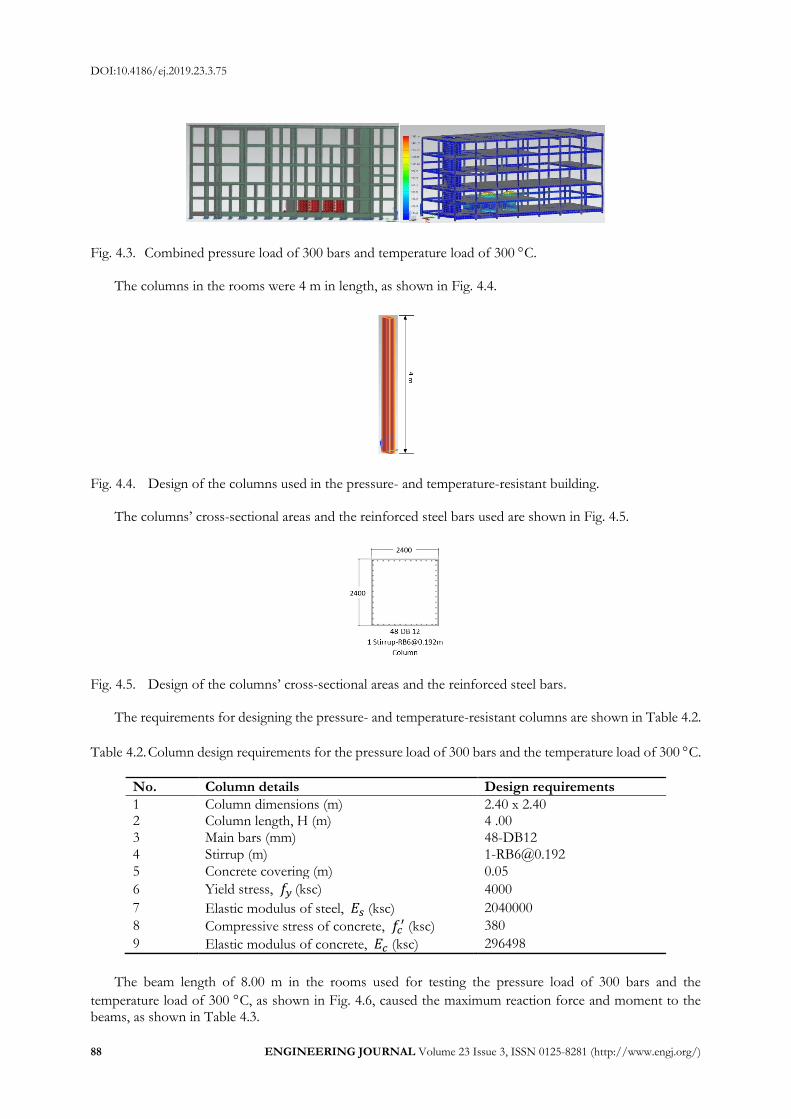
Fig. 4.3. Combined pressure load of 300 bars and temperature load of 300 C.
The columns in the rooms were 4 m in length, as shown in Fig. 4.4.
Fig. 4.4. Design of the columns used in the pressure- and temperature-resistant building.
The columns’ cross-sectional areas and the reinforced steel bars used are shown in Fig. 4.5.
Fig. 4.5. Design of the columns’ cross-sectional areas and the reinforced steel bars.
The requirements for designing the pressure- and temperature-resistant columns are shown in Table 4.2.
Table 4.2. Column design requirements for the pressure load of 300 bars and the temperature load of 300 C.
No. Column details Design requirements
1 Column dimensions (m) 2.40 x 2.40 2 Column length, H (m) 4 .00 3 Main bars (mm) 48-DB12 4 Stirrup (m) [email protected]
5 Concrete covering (m) 0.05
6 Yield stress, 𝑓𝑦 (ksc) 4000
7 Elastic modulus of steel, 𝐸𝑠 (ksc) 2040000
8 Compressive stress of concrete, 𝑓𝑐′ (ksc) 380
9 Elastic modulus of concrete, 𝐸𝑐 (ksc) 296498
The beam length of 8.00 m in the rooms used for testing the pressure load of 300 bars and the
temperature load of 300 C, as shown in Fig. 4.6, caused the maximum reaction force and moment to the beams, as shown in Table 4.3.

DOI:10.4186/ej.2019.23.3.75
ENGINEERING JOURNAL Volume 23 Issue 3, ISSN 0125-8281 (http://www.engj.org/) 89
Table 4.3. Maximum reaction force and moment caused to the beams.
Combined beam pressure load of 300 bars and
temperature load of 300 C
Items Beams Reaction force (N) 84902800 Reaction moment (N-mm) 4388975000
Fig. 4.6. Design of the beams used in the pressure- and temperature-resistant building.
The beams’ cross-sectional areas and the reinforced steel bars used are shown in Fig. 4.7.
Fig. 4.7. Design of the beams’ cross-sectional areas and the reinforced steel bars.
The requirements for designing the pressure- and temperature-resistant beams are shown in Table 4.4.
Table 4.4. Beam design requirements for the pressure load of 300 bars and the temperature load of 300 C.
No. Beam details Design requirements
1 Beam dimensions (m) 1.50 x 2.00 2 Beam length, H (m) 8 .00
3 Main bars (mm)
15-DB28,12-DB28, 15-DB28,15-DB32 9-DB32,9-DB32, 25-DB25,28-DB28
4 Stirrup (cm) [email protected] 5 Concrete covering (m) 0.05
6 Yield stress, 𝑓𝑦 (ksc) 5000
7 Elastic modulus of steel, 𝐸𝑠 (ksc) 2040000
8 Compressive stress of concrete, 𝑓𝑐′ (ksc) 320
9 Elastic modulus of concrete, 𝐸𝑐 (ksc) 272085
The slab dimensions of 8.00 m x 6.00 m in the rooms used for testing the pressure load of 300 bars and
the temperature load of 300 C, as shown in Fig. 4.8, caused the maximum reaction force and moment to the slabs, as shown in Table 4.5.
Table 4.5. Maximum reaction force and moment caused to the slabs.

DOI:10.4186/ej.2019.23.3.75
90 ENGINEERING JOURNAL Volume 23 Issue 3, ISSN 0125-8281 (http://www.engj.org/)
Combined slab pressure load of 300 bars and temperature
load of 300 C
Items Slabs Reaction force (N) 73432620 Reaction moment (N-mm) 670105000
Fig. 4.8. Design of the slabs used in the pressure- and temperature-resistant building.
The slabs’ cross-sectional areas and the reinforced steel bars used are shown in Fig. 4.9.
Fig. 4.9. Design of the slabs’ cross-sectional areas and the reinforced steel bars.
The requirements for designing the pressure- and temperature-resistant slabs are shown in Table 4.6.
Table 4.6. Slab design requirements for the pressure load of 300 bars and the temperature load of 300 C.
No. Slab details Design requirements
1 Slab dimensions (m) 8.00 x 6 .00 2 Slab thickness (cm) 50.00 3 Main bars (mm) DB25@60 4 Concrete covering (cm) 0.05
5 Yield stress, 𝑓𝑦 (ksc) 4000
6 Elastic modulus of steel, 𝐸𝑠 (ksc) 2040000
7 Compressive stress of concrete, 𝑓𝑐′ (ksc) 280
8 Elastic modulus of concrete, 𝐸𝑐 (ksc) 254512
5. Summary The structure design for pressure and temperature-resistant building. As followed ACI 318-08 of building structure design standard code with column, beam and slab 5.1 Table 5.1 shows the results of the three structural design tests on the columns: the high-pressure (HP)
test (300 bars), the high-temperature (HT) test (300 C), and the high-pressure/high-temperature (HP/HT)
test (300 bars and 300 C).

DOI:10.4186/ej.2019.23.3.75
ENGINEERING JOURNAL Volume 23 Issue 3, ISSN 0125-8281 (http://www.engj.org/) 91
Table 5.1. Comparison of the structural properties of the columns.
Items HP test HT test HP/HT test
Reaction force (N) 43704296 2431292.75 46135588.75 Reaction moment (N-mm) 7259233280 18412986 7277646266 Dimensions of columns’ cross-sectional areas (m)
2.20 x 2.20 0.50 x 0.50 2.40 x 2.40
Compressive stress of concrete 𝑓𝑐′(ksc) 380 380 380
Yield stress of steel bars 𝑓𝑦(ksc) 4000 2400 4000
The columns’ cross-sectional areas and the reinforced steel bars used for the HP, HT, and HP/HT tests
are shown in Fig. 5.1.
Fig. 5.1. Designs of the columns’ cross-sectional areas and the reinforced steel bars.
Table 5.2 shows the results of the three structural design tests on the beams: the high-pressure (HP) test
(300 bars), the high-temperature (HT) test (300 C), and the high-pressure/high-temperature (HP/HT) test
(300 bars and 300 C). Table 5.2. Comparison of the structural properties of the beams.
Items HP test HT test HP/HT test
Reaction force (N) 83,746,000 1,156,800 84,902,800
Reaction moment (N-mm) 4,326,300,000 62,675,000 4,388,975,000
Dimensions of beams’ cross-sectional areas (m)
1.50 x 2.00 0.30 x 0.30 1.50 x 2.00
Compressive stress of concrete 𝑓𝑐′ (ksc) 320 320 320
Yield stress of steel bars 𝑓𝑦 (ksc) 5000 2400 5000
The beams’ cross-sectional areas and the reinforced steel bars used for the HP, HT, and HP/HT tests
are shown in Fig. 5.2.
Fig. 5.2. Designs of the beams’ cross-sectional areas and the reinforced steel bars.

DOI:10.4186/ej.2019.23.3.75
92 ENGINEERING JOURNAL Volume 23 Issue 3, ISSN 0125-8281 (http://www.engj.org/)
Table 5.3 shows the results of the three structural design tests on the slabs: the high-pressure (HP) test
(300 bars), the high-temperature (HT) test (300 C), and the high-pressure/high-temperature (HP/HT) test
(300 bars and 300 C). Table 5.3. Comparison of the structural properties of the slabs.
Items HP test HT test HP/HT test
Reaction force (N) 72,967,000 465,620 73,432,620 Reaction moment (N-mm) 607,430,000 62,675,000 670,105,000 Dimensions of slabs’ cross-sectional area (m)
8.00 x 6.00 x 0.30
8.00 x 6.00 x 0.25
8.00 x 6.00 x 0.50
Compressive stress of concrete
𝑓𝑐′ (ksc)
280 240 280
Yield stress of steel bar 𝑓𝑦 (ksc) 4000 2400 4000
The slabs’ cross-sectional areas and the reinforced steel bars used for the HP, HT, and HP/HT tests are
shown in Fig. 5.3.
Fig. 5.3. Designs of the slabs’ cross-sectional areas and the reinforced steel bars.
6. Conclusions It can be concluded from the present findings that (1) pressure loads on structures are greater than temperature loads, (2) the cross-sectional areas and the hardness of structural components, such as concrete and reinforced steel bars, affect their pressure and thermal resistance, (3) the dimensions of buildings constitute vital factors in the design of their structural components, and (4) pressure from explosions is generally greater than the load allowances of buildings. These parameters must therefore be taken into consideration in designing pressure- and temperature-resistant buildings.
References [1] W. L. Bounds, Design of Blast Resistant Buildings in Petrochemical Facilities. ASCE Publications, 2010. [2] Design of Structures to Resist the Effects of Accidental Explosions, US Department of the Army Technical
Manual, TM5-1300, 1990. [3] Design Guide 26 Design of Blast Resistant Structures, AISC, 2013. [4] Design of Structures to Resist Nuclear Weapons Effects, ASCE, 1985. [5] C. J. Oswald, “Blast design considerations for structural engineers,” 2007. [6] J. A. Clarke, Energy Simulation Building Design, 2nd ed. Environmental Engineering, University of
Strathclyde, Glasgow, Scotland, 2001. [7] J. E. Shepherd, “Structural response to explosions,” presented at 1st European School on Hydrogen Safety,
Olster, California Institute of Technology, 2007. [8] D. N. Bilow and M. E. Kamara, “Fire and concrete structures,” in Proc. Conf. Structures: Crossing Borders,
ASCE, 2008.

DOI:10.4186/ej.2019.23.3.75
ENGINEERING JOURNAL Volume 23 Issue 3, ISSN 0125-8281 (http://www.engj.org/) 93
[9] International Building Code Section 1602.1., 2006. [10] Euro code, EN 1990 – Basis of structural design section 4.1.1, 1990. [11] Euro code, EN 1991-1-1, 1: Actions on Structures – Part 1-1: General actions – densities, self-weight, imposed loads
for buildings section 3.2, 1991. [12] Building code Requirement for Structural Commentary, American Concrete Institute, ACI318, 1941. [13] H. Draganić and V. Sigmund, “Blast loading on structures,” Technical Gazette, vol. 19, no. 3, pp. 643-652,
2012. [14] Minimum Design Loads for Buildings and Other Structures, American Society of Civil Engineers, ASCE/SEI
7-05, 2006, p. 1. [15] Eurocode, EN 1990. 0: Basis of structural design “1.5.3.1”, Bruxelles, European Committee for
Standardization, 2002. [16] T. Ngo, P. Mendis, A. Gupta, and J. Ramsay, “Blast loading and blast effects on structures–An
overview,” Electronic Journal of Structural Engineering, vol. 7, no. S1, pp. 76-91, 2007. [17] G. F. Kinney and K. J. Graham, “Internal blast,” in Explosive Shocks in Air. 1985, ch. 9. [18] Hazardous Areas Classification - European Standard. [19] G. Le Blanc, M. Adoum, and V. Lapoujade, “External blast load on structures–Empirical approach,” in
5th European LS Dyna Users Conference, France, May 2005. [20] NATO Handbook on the Medical Aspects of NBC Defensive Operations A Med P-6(B) Chapter 3. Effects of Nuclear
Explosions, Feb. 1996. [21] S. Lamont, “The behaviour of multi-storey composite steel framed structures in response to
compartment fires,” Doctor of Philosophy, University of Edinburgh, 2001.


![Computational Engine Structural Analysis - NASA · Computational Engine Structural Analysis (NASA-T_] ... engine structural component modeling, (3) ... resistant fan blades using](https://static.fdocuments.in/doc/165x107/5ae5b62f7f8b9a29048c9bb9/computational-engine-structural-analysis-nasa-engine-structural-analysis-nasa-t.jpg)