Structural Behavior of Long Span Prestressed Concrete Cable-stayed Bridge With Unequal Height of...
94
Southwest Jiaotong University Master Degree Thesis Page I Classified Index: U448.27 U.D.C: Southwest Jiaotong University Master Degree Thesis STRUCTURAL BEHAVIOR OF LONG SPAN PRESTRESSED CONCRETE CABLE- STAYED BRIDGE WITH UNEQUAL HEIGHT OF PYLONS Grade: 2009 Candidate: Didier D. BOKO-HAYA Academic Degree Applied for: Master Degree Speciality: Bridge & Tunnel Engineering Supervisor: Prof. Li Yadong May, 2013
-
Upload
boko-haya-d-didier -
Category
Documents
-
view
41 -
download
7
Transcript of Structural Behavior of Long Span Prestressed Concrete Cable-stayed Bridge With Unequal Height of...

Southwest Jiaotong University Master Degree Thesis Page I
Classified Index: U448.27 U.D.C:
Southwest Jiaotong University
Master Degree Thesis
STRUCTURAL BEHAVIOR OF LONG SPAN PRESTRESSED CONCRETE CABLE-
STAYED BRIDGE WITH UNEQUAL HEIGHT OF PYLONS
Grade: 2009
Candidate: Didier D. BOKO-HAYA
Academic Degree Applied for: Master Degree
Speciality: Bridge & Tunnel Engineering
Supervisor: Prof. Li Yadong
May, 2013

Southwest Jiaotong University Master Degree Thesis Page II
The core purpose of this thesis was to investigate the structural behavior of the
Second Fuling Wujiang River Bridge, which is a long-span prestressed concrete (PC)
cable-stayed bridge (CSB) in China with unequal height of pylons. In this thesis, an
improved approach for the structural behaviour of long-span prestressed concrete ca-
ble-stayed bridge with unequal height of pylons was proposed using full finite element
analysis (FEA) model of the bridge. Works carried out in this research considered
background knowledge and structural behavior (such as displacement, stress, stability
and natural vibration factor) during construction and operation stages of the project.
Finally dynamic analysis on the seismic effect and wind stability resistance was carried
out. The results showed that: each member of the superstructure possesses greater
safety factors, which means the design had met the requirements.

Southwest Jiaotong University Master Degree Thesis Page III
Abstract
With the growth, complexity and size in traffic flow throughout the world in the past
years, use of modern Prestressed Concrete (PC) technique emanated in the field of
bridge engineering. This kind of technique was a solution for the need to control struc-
tural behavior on elements in bridges. Hence, over a period of time, bridge engineers
generated a large pattern for utilization. And as a result of this development in the use
of the technique today, most bridge structures are built and have become popular
worldwide. However, the cable-stayed bridge (CBS) with unequal height of pylons is
rare. Some of the salient information about this type of bridge included: structural be-
havior and design parameters, and good design in terms of ability to accurately foretell
the field response of the final structure to all types of loading. As competition in the
cables-stayed bridge was approaching its stiffest levels, insight into the information de-
rived from these researches provided better services while gaining a competitive edge
in terms of economy, aesthetics, bridge superior appearance, bridge safety, quick, effi-
cient construction and long-span capabilities. However, the magnitude of this field has
recently become so immense that analysis manual is not feasible any more. Therefore,
more perplexed analysis was essential to get such detail from the structural behavior.
These techniques have been proved to perform very important tasks such as static, sta-
bility and dynamic behavior. Engineers, probably the most important of all the above
tasks, can be simply writing up as a process of bridge guideline. Some few works has
been done with the aim of generating recommendations to this kind of bridge which
can help bridge engineers to take some decisions based on the new detail mined from
the large amount of data for CSB with unequal height of pylons building up.
The cable-stayed bridge with unequal height of pylons rules requires that the bridge
engineers have to define important parameters which should be the minimum document
and confidence. But this is so hard to set when no background information concerning
the dataset is clearly known.
This research primarily investigated the potential of the Second Fuling Wujiang
River Bridge, cable-stayed bridge with unequal height of pylons approach in improving
its performance. A detailed study of the structural behavior of the asymmetric long-span
Prestressed Concrete Cable-Stayed Bridge using unequal height of pylons was pro-
posed. An improved approach was also proposed. Based on the Chongqing Second

Southwest Jiaotong University Master Degree Thesis Page IV
Fuling Wujiang River Bridge, an asymmetric cable-stayed bridge with unequal height
of pylons was simulated by using FEM programs MIDAS/Civil software. To accom-
plish these tasks, the bridge structural behaviour on both, construction and operation
phase such as displacement, stress, stability and natural vibration factor has been ana-
lyzed. The following results were obtained: the girder static performance, investigated
by FEM models the cables and pylons. Furthermore, the girder under construction was
analyzed. Finally, dynamic analysis was carried out on the seismic effect and stability
resistance of the bridge. These results showed that the bridge structural behaviour satis-
fied the requirement of the related design codes and proved to be reliable. These results
can later be interpreted or labeled according to the cable-stayed bridge specific re-
quirements.
Key words: Structural behavior; cable-stayed bridge; Finite Element Method, asym-
metric; unequal height of pylons.

Southwest Jiaotong University Master Degree Thesis Page V
TABLE OF CONTENTS
Abstract ...................................................................................................................... III
TABLE OF CONTENTS ............................................................................................ V
LIST OF FIGURES .................................................................................................. VII
LIST OF TABLES ..................................................................................................... IX
LIST OF NOTATIONS AND ABBREVIATIONS ................................................... X
1. NOTATIONS .................................................................................................... X
1.1 ROMAN UPPER CASE LATERS .......................................................... X 1.2 Roman lower case letters......................................................................... XI
1.3 Greek lower case letters ......................................................................... XII
2. ABBREVIATIONS ......................................................................................... XII
ACKNOWLEDGEMENTS .................................................................................... XIII
CHAPTER 1 INTRODUCTION............................................................................ 1
1.1 DEVELOPMENT AND CHARACTERISTICS ................................................ 1
1.2 HISTORICAL EVOLUTION ............................................................................ 5
1.3 ENGINEERING BACKGROUND AND SIGNIFICANCE ............................. 7 1.3.1 Engineering background ........................................................................... 7
1.3.2 Significance of the research .................................................................... 11
1.4 OBJECTIVES ................................................................................................... 12
1.5 SCOPE AND METHODOLOGY .................................................................... 13
1.6 THESIS OUTLINE .......................................................................................... 14
CHAPTER 2 STRUCTURE ANALYSIS AND CONSTRUCTION ................ 15
2.1 BASIC PRINCIPLES AND IDEAS OF THE FE ANALYSIS ....................... 15 2.1.1 Static analysis .......................................................................................... 17 2.1.2 Dynamic analysis .................................................................................... 17
2.1.3 Stability analysis ..................................................................................... 18
2.2 CONSTRUCTION METHODS ....................................................................... 20
CHAPTER 3 STATIC PERFORMANCE .......................................................... 23
3.1 THE STRUCTURE FINITE ELEMENT MODEL .......................................... 23 3.1.1 Computational model .............................................................................. 23
3.1.2 Calculation parameters ............................................................................ 26
3.2 CONSTRUCTION PROCESS ANALYSIS ..................................................... 35
3.2.1 Construction stages definition ................................................................. 35
3.2.2 The maximum double cantilever stage.................................................... 39
3.2.3 Stress and displacement analysis in construction .................................... 40
3.2.4 Cable force on construction and finished dead state ............................... 42
3.3 COMPLETED STATE ANALYSIS ................................................................ 43
3.3.1 Analysis of distributed load effects ......................................................... 43

Southwest Jiaotong University Master Degree Thesis Page VI
3.3.2 Effect analysis of load combination ........................................................ 49
3.3.3 Limited state analysis .............................................................................. 52
3.4 BRIDGE STABILITY ANALYSIS ................................................................ 55
3.4.1 Bridge stability analysis .......................................................................... 56
3.5 SUMMARY ...................................................................................................... 59
CHAPTER 4 DYNAMIC PERFORMANCE ..................................................... 60
4.1 STRUCTURE DYNAMIC ANALYSIS THEORY OVERVIEW .................... 60 4.1.1 FE method for solving natural vibration frequencies and mode shapes . 63
4.1.2 Dynamic analysis of the earthquake........................................................ 64
4.1.3 Vibration characteristics analysis results. ............................................... 65
4.2 SEISMIC PERFORMANCE ............................................................................ 68
4.3 SUMMARY ...................................................................................................... 74
CHAPTER 5 CONCLUSION AND FUTURE WORK ..................................... 75
5.1 CONCLUSIONS ............................................................................................. 75
5.2 FUTURE WORK .............................................................................................. 76
REFERENCES ......................................................................................................... 77

Southwest Jiaotong University Master Degree Thesis Page VII
LIST OF FIGURES
Figure 1.1 View of different styles of cable-stayed bridges with different heights of pylons................. 6
Figure 1.2 General layout of Fuling River Bridge over Wujiang River (Units: cm)............................... 9
Figure 1.3 Arrangement plan of the main tower section (Units: cm) ...................................................... 9
Figure 1.4 Arrangement plan of deck section (Units: cm) ...................................................................... 9
Figure 3.1 Overall linkage model ......................................................................................................... 25
Figure 3.2 Elastic link ........................................................................................................................... 25
Figure 3.3 Pier and Girder .................................................................................................................... 25
Figure 3.4 Full bridge cross section (transversal) ................................................................................. 26
Figure 3.5 Configuration of both towers elevation with its cross sections ........................................... 27
Figure 3.6 Configuration of cables (106 cables from higher to lower tower) ....................................... 28
Figure 3.7 Main beam prestressed steel beam layout ............................................................................ 29
Figure 3.8 Stress of the girder and tower upper edge ............................................................................ 39
Figure 3.9 Stress of the girder and tower lower edge ............................................................................ 39
Figure 3.10 Stress of the cables ............................................................................................................ 40
Figure 3.11 Displacement of towers top at different construction stages ............................................. 40
Figure 3.12 Stresses in Seg.No.0 of girder at different construction stages .......................................... 41
Figure 3.13 Stresses of both towers bottom section at different construction stages ............................ 41
Figure 3.14 Stresses at the upper flange of tower and girder on dead load at completed stage ............ 44
Figure 3.15 Stresses at the lower edge of tower and girder on dead load at completed stage ............... 44
Figure 3.16 Stressed in all cables on dead load at completed stage ...................................................... 44
Figure 3.17 Structure displacement on dead load at completed stage (unit: cm) .................................. 44
Figure 3.18 Stresses at the upper flange of tower and girder on live load at completed stage .............. 46
Figure 3.19 Stresses at upper flange of tower and girder on dead and live load at completed stage .... 46
Figure 3.20 Stress amplitude on live load at completed stage .............................................................. 46
Figure 3.21 Maximum displacement under vehicle load -City A ......................................................... 47
Figure 3.22 Minimum displacement under vehicle load -City A .......................................................... 47
Figure 3.23 Displacement under pedestrian load .................................................................................. 47
Figure 3.24 Action of the main beam displacement under live load (Pedestrian+ City A) ................... 48
Figure 3.25 Stress envelope in the structure upper edge under ultimate limit state .............................. 53
Figure 3.26 Stress envelope in the structure lower edge under ultimate limit state .............................. 53
Figure 3.27 Stress of all cables under ultimate limit state..................................................................... 53
Figure 3.28 Displacement of all structure under ultimate limit state .................................................... 53
Figure 3.29 Stress envelope in the structure upper edge under serviceability limit state ...................... 54
Figure 3.30 Stress envelope in the structure lower edge under serviceability limit state ...................... 54
Figure 3.31 Stress of all cables under serviceability limit state ............................................................ 55
Figure 3.32 Displacement of all structure under serviceability limit state ............................................ 55
Figure 3.33 Configuration of first five buckling mode ......................................................................... 57
Figure 3.34 Configuration of the first five instability modes diagram .................................................. 59

Southwest Jiaotong University Master Degree Thesis Page VIII
Figure 4.1 Free vibration mode shapes ................................................................................................. 67
Figure 4.2 Seismic wave ....................................................................................................................... 69
Figure 4.3 Stress of the bridge upper edge under load combination I ................................................... 71
Figure 4.4 Stress of the bridge lower edge under load combination I ................................................... 71
Figure 4.5 Stress of the bridge upper edge under load combination II ................................................. 72
Figure 4.6 Stress of the bridge lower edge under load combination II ................................................. 72
Figure 4.7 Stress of the bridge upper edge under load combination III ................................................ 72
Figure 4.8 Stress of the bridge lower edge under load combination III ................................................ 73
Figure 4.9 Stress envelop on upper edge of the bridge ......................................................................... 73
Figure 4.10 Stress envelop on lower edge of the bridge ....................................................................... 73

Southwest Jiaotong University Master Degree Thesis Page IX
LIST OF TABLES Table 1.1 Selected Cable-Stayed Bridges with different heights of pylons ............................................ 7
Table 1.2 Input-output ............................................................................................................................ 8
Table 1.3 Main Geometric Data of Fuling Wujiang River Bridge ........................................................ 10
Table 2.1 Different staging construction ............................................................................................... 21
Table 3.1 Number of nodes and different elements .............................................................................. 24
Table 3.2 Cable parameter .................................................................................................................... 29
Table 3.3 Material parameters .............................................................................................................. 30
Table 3.4 Summarizes the material properties for the cables ................................................................ 32
Table 3.5 Load parameters .................................................................................................................... 33
Table 3.6 Construction stages/phases definitions ................................................................................. 36
Table 3.7 Construction and finished cable force ................................................................................... 42
Table 3.8 Cable forces and stresses on dead load at completed stage with creep and shrinkage of 10 years concrete .................................................................................................................. 45
Table 3.9 Most unfavorable stress in control section under all kinds of loads (unit: MPa) .................. 48
Table 3.10 Load combination ............................................................................................................... 49
Table 3.11 Most unfavorable stress in control section under the load combination above (unit: MPa)..................................................................................................................................... 50
Table 3.12 Five first-order condition stable coefficient results ............................................................. 56
Table 3.13 Five first-order condition Instability modes coefficient results .......................................... 58
Table 4.1 Vibration characteristic value table at the completion state .................................................. 66
Table 4.2 First 50 order cycles and effective converted vibration mass ratio ....................................... 69

Southwest Jiaotong University Master Degree Thesis Page X
LIST OF NOTATIONS AND ABBREVIATIONS
1. NOTATIONS
1.1 ROMAN UPPER CASE LATERS
E Modulus of elasticity 2/N m
F Force [ ]N
M Moment
KD The structure of the overall elastic stiffness matrix;
KG Overall geometric stiffness matrix structure;
KDL Geometric nonlinearity elastic stiffness of the overall structure matrix;
F∆ External load increment
KT Tangent stiffness matrix
G Shear modulus
eqE Equivalent elastic modulus of the inclined cables
A Area 2m
D Displacement dynamic amplification factor
F Force [ ]N
I Moment of Inertia 2mm
L Length [ ]m
T Period time [ ]s
K Stiffness matrix 3/EI L
C Damping matrix Mass matrix
P External force (dynamic loads) vector
L Load
DL Dead Load
LL Live Load (include vehicle load and pedestrian load)
IL Imposed Load
Kh Horizontal seismic coefficient
Kv Vertical seismic coefficient or damping coefficient

Southwest Jiaotong University Master Degree Thesis Page XI
1.2 Roman lower case letters
A Acceleration 2/m s
m Distributed designing bending momen [ ].kN m
k Spring constant [ ]/N m
ls Length of Side Span [ ]m
lm Length of Middle Span [ ]m
λ Stability safety factor
δ Node displacement matrix
δ∆ Variation of nodes displacement matrix
η Equation order
ηλ Eigen values
conσ Concrete tensile stress:
pkf Compressive strength of concrete
ψ Creep coefficient
ε Shrinkage strain:
µ Pipe friction factor
κ Pipeline deviation coefficient: γ Weight per unit volume of cable steel
cl Length of the cable stays horizontal projection in m
σ Stress of the strand (tension in the cables), in 2/N mm
� Displacement [ ]m
xɺ Velocities
xɺɺ Accelerations
, u v Element displacement
ℓ Mass Density
ω Natural frequency [ ]Hz
� Acceleration vector 2/m s
c Damping coefficient [ ]. /N s m
v Velocity [ ]/m s
f Frequency [ ]Hz

Southwest Jiaotong University Master Degree Thesis Page XII
1.3 Greek lower case letters
ν Poissons ratio [ ]−
ωd Damped angular frequency [ ]/rad s
ωi Natural frequency of the load [ ]Hz
2. ABBREVIATIONS
FEM Finite Element Method FEA Finite Element Analysis RC Reinforced Concrete DC Diameter of cables PC Prestressed Concrete DOF Degrees of freedom Max Maximum Min Minimum Seg. Segment No. Number BC Boundaries conditions CS Construction Stage ACAF All Cable Adjusted Force IF Initial Force LTAF Lower Tower Adjusted force PTH8/9/10' Patch Tendon H8/9/10’ CA H7' Cable Adjusted H7' SWJTU South West Jiaotong University SLS Serviceability Limit State ULS Ultimate Limit State M Mass per unit length I Moment of Inertia STI System Temperature Increase PTDCG Positive Temperature Difference between Cable and Girder TIGR Temperature Increase in Girder Roof TIOST Temperature Increase in One Side of a Tower STD System Temperature Decrease NTDCG Negative Temperature Difference between Cable and Girder TDGR Temperature Decrease in Girder Roof ACS Adjust Cable stage 2 LT Lower Tower HT Higher Tower

Southwest Jiaotong University Master Degree Thesis Page XIII
ACKNOWLEDGEMENTS
First and foremost, my due thanks go to the Almighty God for all his love, protec-
tion and guidance that has been with me up to the present time.
I would like to thank my advisor, mentor, Professor LI YADONG, the heads, De-
partment of Bridge Engineering in SWJTU for seeing me through this long journey.
Most importantly, his kind of instruction in research ways, academic rigor, patience
and guidance at critical points are invaluable and worth emulating. Without his support,
guidance and vision this project would have not been made possible. Despite his busy
agenda, Prof. LI has always made time to read through, edit and discuss over my pro-
ject ideas. Apart from his strange technical skills, and his deep knowledge of the pro-
fessional area, he provided me with very useful experience and views related to various
aspects of professional life that have contributed greatly to the successful of my work. I
will forever be indebted to him for his generosity, for having faith in my abilities and
for helping me make this significant work experience highly agreeable. I would also
like to thank his family, especially his wife Xu Huifen Laoshi for all her excellent
mother role, for their friendship and support through the years.
I would also like to thank the following people for their support in this endeavor:
♦ Dr. YAO Changrong, other advisor, and mentor, who has been a role model to me
during this dissertation.
♦ Prof. LI YONGLE, other mentor who has also been a role model to me.
♦ Dr. Zhang XUN, Dr ZHOU, Mr. GU Ying and WANG Hupeng thank for your help
and friendship.
♦ Mr. Zhang Qin, brother and best friend, role model, Zhang Qin has helped me out
more than a few times, and his ability is unmatched.
♦ I would like to extend my appreciation to my colleagues, with whom I share the
supervision of Prof. LI, for being dependable reference points when testing my
ideas.
♦ Besides, I am grateful to their classmates who helped me. It was very appreciable to
have such kind of friends.
♦ Also, my special thanks go to Beninese as well as to Chinese Governments for
kindly granting me the esteemed scholarship for this thesis. In this regard, I

Southwest Jiaotong University Master Degree Thesis Page XIV
sincerely thank all the officers and staff of the Foreign Affairs Office who have been
along with us every times.
♦ I especially want to extand word of thanks to Prof. AWANOU C. Norbert, Prof. B.
KOUNOUEWA and Prof. A. AKPO, who’s the first one, is the head Director and the
others the LPR technical staff. You have been very kind to us, going above and
beyond your duties to help us and many other students else. The University (UAC)
is very lucky to have you.
♦ G. KOTO N’GOBI and O. MAMADOU, thank to both of you for your friendship.
♦ To my brother Koffi TOGBENOU, we have shared many experiences all the time.
♦ My sincere thanks also go to all these professors I have had in class for being
accommodating and patient for my difficult time.
As you know, words cannot express my all feeling and most sincere gratitude to
my wonderful parents, my sisters, brothers, friends and relatives for them moral sup-
port. Without their love, endless support, and understanding, this would have not been
possible. They are the main reasons I have been able to reach this point. This project is
dedicated to all of them whose has been an integral part of my success.
Didier D. BOKO-HAYA
CHINA, May 2013

Southwest Jiaotong University Master Degree Thesis Page 1
Chapter 1 INTRODUCTION
1.1 DEVELOPMENT AND CHARACTERISTICS
The first cable-stayed bridges in modern times were developed by European bridge
engineers. It was founded in the 17 th and 18th century respectively by Faustus Verantius
(1617) and Immanuel Löscher (1784). As steel was not yet identified back then, strings
and wood were used instead of cables [1-2].
In 1823, the famous French Engineer and scientist Claude Navier published the re-
sults of a study on bridges with the deck stiffened by wrought iron chains taking both,
fan/harp shaped system, into consideration.
Suspension combining system idea with stays to achieve more efficient structural
systems had not been completely forgotten after the days of Brooklyn Bridge, New
York, USA in 1883. Thereby, in 1938 Dischinger proposed a system in which the cen-
tral part of the span was carried by a suspension system whereas the outer parts were
carried by stays radiating from the pylon top. It was suggested for a cable supported
bridge with a main span of 750 m long to be built across the Elbe River in Hamburg.
After World War II (1939-1945), German engineers pioneered the design of cable-
stayed bridges to obtain optimum structural performance from material like steel which
was in short supply. To improve the highway transportation system, innovation and in-
expensive bridge design challenge were founded by German engineers to change most
of the Rhine and Elbe river crossings which were destroyed during World War II.
But many of these early bridges collapsed because the numeric calculation methods
were rather sketchy. Disappeared for over a century, it reappeared in the mid-1950s and
exceeded almost all competing systems so far in both bridges in rail and road. Engi-
neers then begin a new era and large extent has been obtain much longer in recent years
for CSB due to the progressed technique of structural analysis tools permitting calcula-
tion of bridge cable forces throughout the erection period and thereby assuring the effi-
ciency of entire cables in the structure. Such kind of calculations was firstly made in
connection with the erection of the Stroemsund Bridge.
Freyssinet (1879–1962) is a great pioneer for concrete bridges built and designed
with the creation of prestress [8]. The goal of using prestress was the complete elimina-
tion of tensile stresses in the concrete and under the action of service loads. Also the
elimination of possible deformations, cracks, and the increase of load capacity gained
from the use of high-strength reinforcement.

Southwest Jiaotong University Master Degree Thesis Page 2
Stroemsund Bridge in Sweden (1955) was the first modern CSB designed and built
in Europe by Dischinger. Since then, many cable-stayed structures with both concrete
and steel bridge decks have been constructed [6, 25, 28, 30, 32,42]. The use of PC technology
until now, has greatly participated in many structures development.
CSB structure reappeared and bridge designers have focused more in its dynamic
performance. Therefore with the span enlargement of the bridge type structure, atten-
tion was given to its seismic stability, wind resistant and vibration [10, 11, 30].
The Theodor H. Bridge across the Rhine was opened to traffic in 1957. With a main
span of 260 m long, it introduced the harp-shaped cable system with parallel stays and
a freestanding pylon.
In 1960, Maracaibo Bridge in Venezuela (8.7km long with 135 spans) was inaugu-
rated two years later, which is the first multi-span PC cable-stayed bridge in the world.
Both of, pylons and deck were made of concrete, thereby introducing a structural mate-
rial that had not before been used in the main elements of cable supported bridges.
The Sunshine Skyway Bridge (1982) in Tampa, Florida, had set a new record for
concrete bridges, with a main span of 365 m long, and was the first CSB to attach ca-
bles to the center of its roadway as opposed to the outer edges. The next year, Dames
Point Bridge in Jacksonville, Florida, exceeded the previous record held by the Sun-
shine Skyway Bridge.
One decade before 1980s, the structural system was confined mainly by United
States and Western Europe; which found application in the past three decades all over
the world because of it economy and elegant appearance. Nowadays, CSB were
adopted widely in Asian countries and most of the bridges with the longest spans are
located in Asia, particularly in China and Japan.
The Yunyang Bridge in Sichuan province, completed in 1975, is one of the earliest
CSB in China. Over the last thirty years, the rapid development of cables structures,
particularly CSB (with medium span over 600 m), reflected the growing interest in
construction. Some famous bridges build included: the (602 m) Shanghai's Yangpu
Bridge (1994) with main span of 602 m, which was surpassed within a half year by the
Normandy France Bridge (1995) with its central span of 856 m long, the Sutong Bridge
(Yangtze River, China in 2008) with central span of 1088 m exceeds the previously re-
cord held by the Tatara Bridge (1999) with central span of 890 m in Japan (Hiroshima),
and come from behind is the Russky Bridge (2012) with central span of 1104 m.

Southwest Jiaotong University Master Degree Thesis Page 3
The project cases above show that this technique could be applied to an area previ-
ously reserved for suspension bridges. CSB structures require modern technology and
high quality materials in which the cables are probably the most important component.
In addition, comparing the RC and PC bridges are more economically competitive and
aesthetically superior due to the employment of high-strength materials. Therefore, in
order to expand span lengths over 1000m, designers have always expected to design
economical structures that are safe, usable, and durable [7,12,14,30,45].
Until today, the box girder section was the last solution found, for PC bridges, to
built greater spans in terms of the bridge’s super structures. And this is due to its char-
acteristics such as the material of construction (timber, concrete and steel or a combina-
tion of materials such as RC, PC deck and steel stringers, typical for many highway
bridges super-structures), the span lengths, the structural forms/types, the load path
characteristics, usage, moveable bridges position and the type of deck for combination.
A great number of CSB fit in with most surrounding environments and can be varied by
modifying the tower and cable arrangements, have been designed and constructed in
the worldwide [3-4]. Thereforte, CSB is becoming more and more fierce and popular
choice in the worldwide. According to the CSB arrangement system, four major basic
classes are keeping until now (Walther, 1981): cables are made nearly parallel by at-
taching cables to various points on the pylon(s) and the height of attachment of each
cable on the pylon is similar to the interval from the pylon along the roadway to its
lower attachment in a harp design. Contrary to a harp, in a fan design all the cables are
connect or pass over the top of the pylon(s). The Semi-Harp system and Asymmetric
system, the common systems in CSB are the fan and harp systems. The first is mostly
used in the form of a changed fan system in which the cable anchorage points are ex-
tend over a certain height at the pylon top. During the rigidity studying offered by the
system of cable stay itself and by deducing that the pylon and the girder provide the
axial resistance while the fan-shaped system was defined by Gimsing as a system
which is stable of the first order [27]. Cable-stays are basically disposed in two disposi-
tions which are two plane systems and single plane systems. Originally, sections of the
box girder were adopted for torsion and lateral rigidity of the deck. A-frames, Trape-
zoidal portal frames, single or twin pylons, inverted Y shaped and other forms are the
various possible shapes of pylon construction and alternative solution to suspension
bridges for long spans [5]. The inverted Y pylon shape, behaves like a rigid closed
section in bending, along with the stays, which significantly reduces possible rotary

Southwest Jiaotong University Master Degree Thesis Page 4
motion of the running surface (deck) [47]. The beam section primary can use box Π-
shaped and other forms. A combination of different forms, such as parallel double, in-
clined or central single cable plane accompanied by a variety of different shape of the
bridge towers, forming the rigid tower and light style floating bridge deck.
CSB is a high statically indeterminate structure which can be analyzed and calcu-
lated in practical application by the method known as FEA. Deformation of the geomet-
ric nonlinear factors must be taken into consideration for long-span CSB. These struc-
tures have been designed with the primary objective of avoiding failure under static and
dynamic loads and can be used to gain insight into the traffic flow.
Furthermore, to the amendment the cable sag nonlinear impact Ernst formula in
1970s has been the CSB as a general linear elastic structure, according to the method of
the ordinary linear displacement theory of structural mechanics analysis, which is an
approximation processing method. But seventy years later, due to the emergence of
long-span CSB, and the development of computational structural mechanics began fi-
nite displacement theory application to the analysis of the cable-stayed bridge up. The
more mature approach is to use the moving coordinate iterative method to consider
large displacements. Ernst formula correction cord elastic modulus considers the stay
cables sag nonlinear impact introducing stability factor to consider the effect of the
beam and column. CSB and others bridges type have some characteristics: span 250 ~
600 m CSB is the most competitive bridge type, 600 ~ 1000 m, and cable-stayed bridge
is the only suspension bridge competition opponents, where the stiffening girder mo-
ments can be reduce. The moments in the girders and supporting pylons can be con-
trolled by a suitable choice of stay cables; uniform distribution of forces in pylons and
deck girders results in efficient material utilization. CSB is adjustable in the construc-
tion process and operated for cable tension adjustment, it has a very important feature.
Developed from the classical suspension bridges with cables anchored at the abut-
ments and supported by solid pylons or towers, CSB deck system is supported by the
hanger cables suspended from the pylons. Relatively to the suspension bridge, the
overall stiffness of CSB which makes it’s under live load deflection is much smaller
than the same span of suspension bridge.
To understand more the behavior of the structure, comparison should be making be-
tween the load/displacement with strength/ductility. These researches enhance the cur-
rent knowledge in understanding the structural behavior of the long-span CSB with un-
equal heights of pylons.

Southwest Jiaotong University Master Degree Thesis Page 5
1.2 HISTORICAL EVOLUTION
Cable-stayed bridge with unequal heights of pylons is rare structure. CSB spanning
250 ~ 600 m is more economical and preferred to conventional ones. On a wide river,
towers of CSB are chosen on a large bridge span so as to ensure that the large span
bridge tower is distributed on both sides of the river shore convenient construction. On
narrow rivers bridge, the span is not big, so can choose single pylon cable-stayed
bridge, but should consider channel navigation situation.
Ganzhuxi Bridge is 402m (1,319ft) long with span combination of 118m (387ft) +
210m (689ft)+74 m (243ft). Jiangxi Bridge deck width is 35m (115ft), see Figure1.1.(a)
Jiangxi Hukou Bridge is 3799m (12,464ft) long and main bridge of 636m (2,087ft)
with span combination of 65m (213ft) + 123m (404ft) + 318m (1,043ft)+130 m (427ft).
Located within the Poyang Lake in Jiujiang city Jiangxi province, the Jiangxi Bridge
deck width is 27.5m (90ft), four traffic lanes and also asymmetric PC cable-stayed
bridge with unequal height of pylons. Starting in November 1997, Jiangxi Bridge was
open to traffic in November 2000, see Figure 1.1. (b)
Wadi Leban, Riyadh Bridge designed by Seshadri Srinivasan, was built between
1993 and 1997. It carries 6 lanes of highway traffic, 763m (2,503ft) of total length and
35.8m (117ft) in width. Pylons respectively reach a height of about 175.5m (576ft) and
167.5m (550ft). Open to traffic in the year 2000, see Figure 1.1. (c)
Jingzhou Yangtze River Highway Bridge is located between Bailuoji of Jianli Coun-
try over the South branch of the river, Jingzhou City, Hubei Province. The structure was
constructed as a CSB with steel box girder. It carried 4 lanes of highway traffic, 4177m
(13,704ft) of total length and 700m (2,297ft) in span. Starting in 1998, Jingzhou Yang-
tze Highway Bridge was open to traffic in 2002, see Figure 1.1. (d)
Yunyang Yangtze River Bridge located at Chongqing, like many other bridges that
are over Three Gorges reservoir, Yunyang Bridge’s total length is 1278.6m (4,195ft)
and 318m (1,043ft) in main span, 104m (341ft) of height which the taller tower is 26m
(85ft) long. Starting in 2002, Yunyang Yangtze Bridge was open to traffic in 2005, see
Figure 1.1. (e)
More bridges cases are shown in the following Table 1.1.
For high and low pylon cable-stayed bridge with auxiliary pier settings, the per-
formance research of stress effect rarely reported in the literature at present.

Southwest Jiaotong University Master Degree Thesis Page 6
Figure 1.1 View of different styles of cable-stayed bridges with different heights of pylons
(a) Ganzhuxi River Bridge; (b) Jiangxi Hukou Bridge; (c) Wadi Laban, Riyadh Bridge; (d)
Jingzhou Yangtze River Bridge; (e) Yunyang Yangtze River Bridge; (f) Second Fuling Wuji-
ang Bridge
(a)
(b)
(c)
(d)
(e)
(f)

Southwest Jiaotong University Master Degree Thesis Page 7
Table 1.1 Selected Cable-Stayed Bridges with different heights of pylons
1.3 ENGINEERING BACKGROUND AND SIGNIFICANCE
1.3.1 Engineering background
(a) Location
Located at Fuling District in Chongqing City, the project of the Fuling Wujiang
River Bridge is about 500m (1,640ft) upstream from the East coast connection, in the
Fuling Jiangdong Zone, and connected with the Fu feng Highway in the West side.
The total bridge length of 1700m (5,577ft) and the main bridge of 590m (1,940ft)
long span combination of 150m (492ft)+340m (1,120ft)+100m (328ft). The bridge is
built by cantilever segmental construction method, asymmetric, PC cable-stayed bridge
with unequal height of pylons/pillars.
Pylons respectively reach a height of about 178.4m (585ft) and 130m (427ft) over
the water, with the towers height to bridge length 66.40m (218ft) and 105.40m (346ft)
as in .1.1.(f). At the deck level, the lower end of cables are anchored to the top of the
middle of the diaphragms of the box girder and the tower foundation depth is about 8m,
underwater depth of 10m or even more.
The bridge deck consists of a composite structure made of steel box girders and C60
(according to Chinese Standard JTJ 23-85) pre-cast RC with girder depth of 3.5m and
deck width of 25.5m (84ft), carrying 4 lanes vehicle traffic and 2 pedestrian lanes sepa-
rated by a 5.5m (18ft) median strip where the central pylons are located. The deck is
mainly supported by 106 cables, which 66 cables for the higher tower and 40 cables for
lower towers, respectively. There are three segments of 6m (20ft), 4.4m (15ft) and 4.2m
(14ft) for cantilever construction. The vehicle speed is, limited to 50 km/h.
Bridge Name Location Countries Main Span(m) Open to Traffic
Shuangbei Chongqing China 330 2009
Jiangxi Hukou Jiangxi China 636 2000
jingzhou Yangtze Hubei China 700 2002
Wadi Leban Riyadh Saudi Arabia 405 2000
Ting Kau Rambler Channel Hong Kong 475 1998
Shandong Binzhou bridge Shandong China 300/300 2004
Yunyang Yangtze River Chongqing China 1278.6 2005
Ganzhuxi main bridge Guangdong China 402 -
Fuling Wujiang Chongqing China 340 2009

Southwest Jiaotong University Master Degree Thesis Page 8
To ensure the Fuling Wujiang bridge life, health monitoring was developed to study
its long-term behavior under normal operating conditions and to evaluate its structural
health condition. In scale, it was the biggest project at Chongqing, which the operation
construction started in October 2004, and was completed in September 25, 2009 with
an overall cost of 36 million Chinese Yuan. It is a rare CSB with asymmetrical towers.
(b) Structure
The framework of this research covers the Second Fuling Wujiang River Bridge
with the total length of 1700m (5,577ft). The main span 340m(1,120ft) long and both
side spans are 150m(492ft) and 100 m(328ft). To arrange a cable-stays spacing of 6,
4.4, and 4.2 meters, and inclined cable position in the both towers of the rope from
unity is 2.0 m. The main girder is of a composite steel box girder structure, which is
based on the deck structure. The bridge has carries 4 lanes of highway traffic and 2 pe-
destrian lanes separated by a 5.5m (18ft) median strip where the central pylons are lo-
cated on the 25.5m (84ft) wide deck. The superstructure is made out of hollow steel
sections, whereas the towers substructures are made of reinforced concrete.
The geometrical parameters are discussed in detail below for the mathematical
model. The side to main span ratio ls/lm has a low value of 150.00/340.00=0.441 and
100.00/340.00=0.294 (Max girder deflection). The towers heights to bridge length ratio
H1/L are 105.40/590.00=0.178 and 66.40/590.00=0.112 (Max tower deflection). The
deck under-surface from the surface of the earth H2/H is respectively 73/178.40=0.409
and 63/129.40=0.487 respectively. Therefore, the box girder in the side span is filled
with concrete to act as a counterweight. Detailed plans on the girder sections and cable
diameter employed in the bridge are given in the chapter3. The dispositions and dimen-
sions of the towers cross sections can be found in the chapter3 as well.
Table 1.2 Input-output
Input Range
Outputs Upper Lower
side to main span ratio ls/lm 0.441 0.294 Max girder deflection
Tower height to bridge length ratio H1/L 0.178 0.112 Max tower deflection
Tower box width 12.20m 7.20m Max tower moment
Tower box depth 14.20m 11.20m Max tower moment

Southwest Jiaotong University Master Degree Thesis Page 9
Figure 1.2 General layout of Fuling River Bridge over Wujiang River (Units: cm)
Figure 1.3 Arrangement plan of the main tower section (Units: cm)
Figure 1.4 Arrangement plan of deck section (Units: cm)

Southwest Jiaotong University Master Degree Thesis Page 10
The main bridge dimensions are shown in the Table1.3 provided below and a sum-
mary of the geometric data can also be seen.
Table 1.3 Main Geometric Data of Fuling Wujiang River Bridge Type of bridge Cable-stayed
Name of the bridge Second Fuling Wujiang River
Name of the river Fuling Wujiang
Location Fuling, Chongqing, China
Total length 1700.00m
Spans length(L) 590.00m
Length main span (lm) 340.00m
Length sides spans 150.00 /100.00m
Height pylon above girder( h) 105.40 / 66.40m
Total height H pylon concrete pylons 178.40 /129.40m
Number of cables main span 53
Number of cables side span 33 / 20
Cable spacing main span 6.00m
Cable spacing side span 4.20 / 4.40m
Segment length 6.00m
Length key-segment 6.00m
Total number of lanes 4Bridge −
Minimum navigational clearance 10.00 m above the river
Number of concrete pylons 2
Towers deck under-surface from the
surface of the earth
73 / 63m
Height of river piers 31.177 m
Total number of piers 1
Total number of piles 59 Reinforced Concrete piles
Depth of piles 25 / 24 / 34 / 35 m
Total number of cables 106
Average weight of cables 10.029 tonnes
Length of cables 30.194 231.323Various from to m
Cable Elastic or Young’s Modulus 1.8073 05 1.9497 05 Various from E to E MPa
Concrete Elastic or Young’s Modulus 3.972 04 4.25 04 Various from E to E Mpa
Steel Elastic or Young’s Modulus 2.05 05E MPa
Mass Density (Concrete) 32500 /Kg m

Southwest Jiaotong University Master Degree Thesis Page 11
1.3.2 Significance of the research
With the growth of traffic flow throughout the world within the past several
years, competition in the modern of using PC technique was one of the most relevant
contributions to bridges engineering domain. In fact, unique in several ways, the cable
stay systems usually modeled using bar/beam element for the global analysis of the
structural response, firstly consist of three major components: cables, main girder and
towers which has many innovations these three decades.
Since these innovations until today, a great number of cable bridges have been de-
signed and constructed worldwide. But there are still some issues which are not solved
yet, although many bridges of this type have been constructed in the world.
The structural girder system is used extensively for medium and long-span, and subse-
quently. It is well known that Eugene Freyssinet was the inventor of PC.
This research helps comprehend the structural behavior of long-span PC cable-
stayed bridge with unequal height of pylons. Unfortunately, today there are many
bridges engineers who do not fully understand the basic principles of the cable-stayed
bridge type design and construction.
In this research, the interrelationship between, yet finished structure and the various
kinds of loads that affect the construction type is a major issue in the actual field opera-
tion. It identifies solutions areas and structural components for static and dynamic of
the similar bridge event in the future.
The overall goal in this thesis is to provide the latest state of the art on similar ca-
bles-stayed bridges type while elaborating upon the fundamentals and possibilities per-
taining described above related problems to such bridge structures. The contents will
relate, the Fuling Wujiang River Bridge at Chongqing, with unequal height of pylons
using prestressed concrete, which was completed and put on traffic in September 2009.
Mass Density (Steel) 37850 /Kg m
Load LL 3.6 kN/m all over the span(4.0 kN/m2 intensity
Poisson’s Ratio, 0.30n=
Diameter of cables (DC) 104.532 136.275Various from to mm
Max road speed 50 / Km h for bridge
Specifications applied China Code
Construction end September 2009
Design life of bridge 100years
Construction Cost RMB 260 million

Southwest Jiaotong University Master Degree Thesis Page 12
We shall try to show from an existing data whether this type of bridge is really a better
solution between Girder Bridge and cable-stayed bridge.
Therefore the structure would be helpful in studying the behavior of bridges under
normal operating conditions. In the particular case of bridges with unequal height of
pylons, it is especially important to choose an appropriate scheme of initial cable forces
while the bridge is under dead load only.
This research is of great business significance to the bridge engineers since the inte-
gration of domain expertise in the structural bridge process is looked forward to push
for better structural results of the customers.
Besides this work will also have an academic significance enclosed to it since which
will form a basis for future extensions to this subject. One common analysis must be
run against the cable-stayed bridge with unequal height of pylons database and find sets
of items that appear together in many cases of this structure. If such kind of task is to be
undertaken, then our research work will not be under-estimated.
1.4 OBJECTIVES
This proposed research primarily aims is to conduct in depth a study of the structural
behavior of long span PC cable-stayed bridge with unequal height of pylons. Specifi-
cally, to improve their performance, these kinds of systems need to have more and more
item-ratings. The design of the bridge makes the relevant recommendations as specific
objectives of this project:
♦ The original design in variety of load combination, which is the characteristics of
bridge structure stress and displacement, will be analyzed and then the horizontal
and vertical stiffness of the bridge checked;
♦ Identify the issues faced by project participators during implementation of cables-
stayed bridge;
♦ Proposal for the first issues how to improve the behavior of the bridge structure
during construction and operating of the process;
♦ Learn civil engineering software as a tool and using skillfully FEM program such
as MIDAS/Civil software;
♦ Simulate and analyze the static and dynamic characteristics of the whole model; ♦ Analyzed the differences in the forces distribution following the connection case
and organized further calculations about the relationship between stiffness of
deck, piers and pylons.

Southwest Jiaotong University Master Degree Thesis Page 13
Moreover, researches include investigating the static and dynamic behavior of
the structural system, seeking to find a remedy for the shortcoming similar exis-
tence and provide a clear and comprehensive definition of this type of structure.
The following are the main questions that the research should answer:
♦ Where we are now (structural system design parameters and criteria)?
♦ What is the structural behavior of long span cable-stayed bridges with unequal
heights of pylons?
♦ What shall we suggest of a layout to give to the future similar bridge design?
1.5 SCOPE AND METHODOLOGY
Our research adopts the general framework for cables-stayed bridge construction
and solely focuses on long span PC cable-stayed bridge with unequal height of pylons.
Moreover, our objectives for this research are to retrieve structural behavior of the
bridge such as the construction method statements, critical factors for implementation
and to check the assumptions made in the structural design of the bridge in order for a
better understanding and establish the baseline model of the bridge for assisting in fu-
ture works.
Our research aims to assess the construction method of cable-stayed bridge with un-
equal height of pylons, problems faced and the critical factors for successfully execu-
tion of this kind of bridge. In order to achieve objectives of this thesis, we have used
the following methods and research techniques:
We have obtained in the form of a design basis note, some specific requirements of
geometric and structural design. A number of statutory procedures such as planning,
consent and land acquisition need to be taken account for this kind of bridge construc-
tion which is at an early stage of development. In order to construct a feature vector for
the cable-stayed bridge with unequal height of pylons, a very large raw of dataset,
needs massive preprocessing before any bridge construction works.
We adopt this uncommon structure to mine interesting relationships between
popular structures by finding out structures frequently appreciated by the same way.
For that purpose, we use the FE method according to the existing Chinese specification
for the structural system [48-53]. The software is the commercial finite element one
named MIDAS/Civil to simulate the complete model and large scale of the design.
Bridge finite element model will be created for static and construction analysis.

Southwest Jiaotong University Master Degree Thesis Page 14
Moreover, multiple plots and figures will show and compare the different shapes.
The various results of the comparative analysis and the meaning of each shape will be
discussed in depth. Structural behavior is beyond the scope of our research. However,
the outcome of this study cannot be the situation of all construction processes in CSB.
1.6 THESIS OUTLINE
We have explored in this chapter, the following topics:
In Chapter 1, we discuss about the long span PC cables-stayed bridge development
and characteristics, the historical evolution of long span PC cable-stayed bridge with
unequal height of pylons and the engineering background behind this research in gen-
eral. Its cover issues of the significance, the objectives, scope as well as the methodol-
ogy used for this research.
In Chapter 2, we discuss the structure analysis and how to build it. We have give
knowledge about the basic principles and ideas of the finite element analysis of long
span PC cable-stayed bridge with unequal height of pylons. We describe in detail the
concept of the designing and have provide the basic theory of static, dynamic and sta-
bility analysis of long span PC cable-stayed bridge .
Chapter 3 discusses the static performance analysis of the structure. The structure fi-
nite element model is put on measures to determine computational model, as well as the
model calculation parameters. We dwell much on stressing, deformation and stability
analysis. The chapter also has different kinds of graphs plotted to show and compare
the performances.
Chapter 4 deals with dynamic performance analysis of the structure. We analyze, in-
terpret and discuss the frequency and mode shapes results obtained under the design
code [50, 51].
In Chapter 5 lastly, we conclude our research; give some recommendations and calls
attention to further related areas of research that may be useful.
Extra to the chapters, additional results and input data for the analysis are provided
in:
NOTATIONS AND ABBREVIATIONS
ACKNOWLEDGEMENTS
REFERENCES

Southwest Jiaotong University Master Degree Thesis Page 15
Chapter 2 STRUCTURE ANALYSIS AND CONSTRUCTION
This chapter covers the technology required for the structure analysis and con-
struction of PC cable-stayed bridges using the cantilever method. The first part deals
with the basic principles and ideas of FE analysis, and pays particular attention to the
static/net charge, live load/dynamic live load and stability analysis of long-span PC ca-
ble-stayed bridges with unequal height of pylons. The second part is dedicated to its
construction methods. Large bridges require a stable construction condition which can
carried heavy loads.
2.1 BASIC PRINCIPLES AND IDEAS OF THE FE ANALYSIS
The cable-stayed bridge is composed of three major components: cables, main
girder and towers. Deck system is generally held up by the cables suspended which
produce compressive forces within and utilised bar elements for the overall structural
response analysis [16]. Its structural mechanics is highly redundant (statically indetermi-
nate) structure, i.e., a structure in which the reactions/internal force cannot be obtained
only from the equations of equilibrium. High strength use of cables in tension leads to
economy in material, weight, and cost. The bridge deck must be involved in the carry-
ing of these forces for economic design. At the points of cable attachments, the stiffen-
ing girder behaves as a continuous beam supported elastically. However, the deck dis-
tributes the loads between the stays under traffic loadings, which work as extending
spring. The use of traditional structural mechanics calculation method of the whole
bridge structure analysis has become very difficult.
During the last two decades, the rapid development of commercially available com-
puter programs, using the theory of FE calculation and analysis in structural design
started to gain recognition and acceptance within the design communities. By the be-
ginning of the 21st century, these approaches start to dominate many structural analysis
procedures, incorporating the total system design. Corresponding FA analysis, software
is also constantly being developed and has been widely utilised in a variety of engineer-
ing practice and scientific research area [9, 18, 21]. Structural FA analysis method is actu-
ally the structure of the matrix displacement method, similar to the basic principles of
structural mechanics displacement method. The basic unknowns are the nodal dis-
placements and equilibrium equations to solve the unknown quantity, and then calculate

Southwest Jiaotong University Master Degree Thesis Page 16
the structure internal forces. The procedure of structure FE analysis solving can be out-
lined as follows: Structural discretization
Structure is usually divided into a number of different members, which is referred to
as a unit suitable for analysis and will be connected with a junction point. The entire
structure has become a limited cell assembly, which is the structural discretization. The
finite deformation with a discrete FE modal is the most powerful tool utilised in the
nonlinear analysis of the recent cable-stayed bridge.
Discretization can be refers to the material area translation process of an object-
based model into an analytical model apt for analysis. In structural analysis, discretiza-
tion can affect two basic analytic model types, containing:
In a 3D system, each node has six DOF, each either constrained or free. The geo-
metric and material properties of the structural elements are then characterized by line
elements which simulate their physical behavior by following the mathematical rela-
tionships. Through application of the direct stiffness method, loading at node locations
translates into displacement and stress fields which indicate structural performance.
FE Model that a meshing procedure created a network of line elements and con-
nected by nodes within a material continuum. Every line element of the local material
simulates the structure physical properties and its geometric as well. The whole system
loading and boundary conditions must be define, and the structural response digital
formulation through the computational model as well.
Element analysis
The fundamental analysis must taken account the establishment of the element stiff-
ness matrix. And each unit must be cut at its ends junction structure internal forces
which acting on the unit cross section at both ends.
Overall analysis
As a synthese of the overall structure, each unit must be set while the deformation
compatibility conditions and the equilibrium conditions at each junction must be satis-
fying. Then to solve these kinds of problems, we must combine the equilibrium condi-
tions of the force with the compatibility conditions of displacements.
Computer codes technology are the main tools of the modern engineering design
process in the structural field. Many computer programs were promoted during the last
several decades in the design of the engineer domain. Structure analysis has been a
great breakthrough abroad and has appeared in many large-scale general-purpose FE

Southwest Jiaotong University Master Degree Thesis Page 17
analysis program, such as MIDAS, ANSYS, MSC/NASTRAN, SAP 2000, Algor (Su-
per Sap), which are an Educational Version, limited in modules, numbers of nodes and
elements available for students and academic staff [9]. Many others programs are also
developed in the academic institutes, but these are completely baseless. On the other
hand, ADINA, ABAQUS and SESAM are used in industry. These procedures pre/post-
processing has a good interface, convenient, powerful computational analysis capabili-
ties and open secondary development system. For bridge engineering industry in the
country, a large number of scholars, engineers design these general-purpose FE analysis
program with the bridge structure to calculate the combination of extensive MIDAS
and ANSYS number. MIDAS is bridge simulation software which has been widely
used in a various bridge design cases and construction calculation. This thesis is to use
MIDAS in space beam/bar element modeling and analysis.
2.1.1 Static analysis
Following the span size, the CSB structure static analysis is calculated using two
theories. For a long-span CSB, cable sag is somehow large, incited the burdening of the
girder which is not easy to solve. Large displacement, bending moment and axial force
components caused by interaction, resulting in nonlinear CSB system factors, and must
adopt deformation theory. When it need high tensile stresses for the last erected cables
step, it apply low tensile stresses to the last cables due to the bending forces which can
make the deck movement increase. The cables elasticity modulus can be modifying
which directly provoke the cables non-linearity aspect. Usually, the sag effect augments
when the cable length is important and in analysis models it is better to calculate by an
iteration process the cable stiffness related to the cable stress in any particular stage or
the effective Young’s modulus can be used [34]. The CSB nonlinear mainly includes ma-
terial, geometric nonlinearity and beam-column effect as well. At present, all adopt
numerical solution method such as incremental, iterative and hybrid method to calcu-
late the approximate solution. Cable static behavior basic formulation was formulated
by Peterson [29] and more details in the recommendation on cable-stays [35].
2.1.2 Dynamic analysis
Accurate dynamic modeling of a cable structure is a particularly difficult problem
due to the nonlinear behavior of cables (large bending and axial deformation effect).
Dynamic forces have an important role in CSB. Therefore, the present work quests the
dynamic behavior of CSB with unequal height of pylons. There is a dynamic response

Southwest Jiaotong University Master Degree Thesis Page 18
by CSB under the influence of the environmental loads such as moving/traffic loading,
the gusts of strong wind and seismic [20, 22]. These influences have the effects as to pro-
voke the vibration of the bridge structure, which augment the static internal forces.
Moreover, in the severe cases can lead to the complete destruction of the bridge struc-
ture. On other hand, the influence of the dynamic deformations of the pylons and also
the serious influence of the axial forces of the stiffening girders/deck, caused by the
cable-tensions excite the bridge in a simultaneous axial dynamic movement. The CSB
dynamic analysis is concerned with its seismic resistant and aerodynamic stability be-
havior of which, it is necessary to determinate the natural frequencies and principal
modes of the bridge structure vibration.
Therefore, bridge design calculation contains the content of the vehicle dynamic ac-
tion of long-span CSB which still needs through the theoretical calculation and wind
tunnel test to test bridge aerodynamic stability.
2.1.3 Stability analysis
The structural design of CSB settlement is to avert sideways, the vertical movements
of the tower and deck under asymmetrical live load. Cables-stayed bridge with long
main span mostly provokes some critical issues, such as large-deformation effects and
stability during its construction. The CSB stability problems experienced in the calcula-
tion method such as: the classical static method (Euler method), Energy method (Ti-
moshenko method), defect law, dynamic method (applies for a real eigenvalue), the
simplified method and FE numerical calculation method. The FE Method is generally
used to arrive at the ideal result, because long-span CSB structure is a complicated and
the classical method which is not very practical. Moreover, the FE Method can be seen
as a special of the Rayleigh-Ritz method, based on the energy variation principle ap-
proximate calculation. The FE Method mathematically view, the infinite degrees of
freedom transformed into limited DOF, thus the differential equation problem into an
algebraic equation problem, which become easy to solve [42]. Hence, the procedures for
solving such problems are numerous and implemented in the general computer FEM
software program. In this research, MIDAS/Civil program has been used to calculate
and solve the stability problem.
First class stability
In the FE calculations, considering the geometric stiffness and the stiffness of the
structure reflects the structure of unstable factors. When the external force increase λ

Southwest Jiaotong University Master Degree Thesis Page 19
times, the force and geometric stiffness matrix also increases λ times, as shows the fol-
lowing formula:
[ ] [ ] { } { } KD KG Fλ δ λ+ =( )
(2.1)
If λ is too large, the structure reaches the equilibrium state and the node displace-
ment matrix { }δ becomes{ } { }δ δ∆+
, and stability equation can be satisfy:
[ ] [ ] { } { } { } KD KG Fλ δ δ λ+ ∆ =( )( + )
(2.2)
Simultaneously conditions satisfying the above two formulas:
[ ] [ ] { } { } 0KD KGλ δ+ ∆ =( )
(2.3)
[ ]KD → Structure overall elastic stiffness matrix;
[ ]KG → Structure overall geometric stiffness matrix;
λ → Scalar multiplier which is the structural stability safety factor.
The calculation of the stability factor characteristic equation, which is order η , and
theoretically the η Eigen values are1 2, .... ηλ λ λ engineering problems.
Second class stability
It is necessary to study also the stability problem of the second class of the cable-
stayed bridge. There are geometric and material nonlinearity due to the CSB, the sec-
ond type of stability problem must take into account the non-linear effects.
Geometric nonlinear method
The cable-stayed bridge geometrically nonlinear incremental equilibrium equations:
One of the methods for solving nonlinear problems is the incremental methods.
The issue in geometric nonlinear analysis is to test the structural system stability, i.e.
determine its critical load.
[ ] [ ] { } { } KDL KG Fδ+ ∆ = ∆( )
(2.4)
[ ]KDL → Considering the geometric nonlinearity elastic stiffness of the overall
structure matrix; with{ }F∆ → External load increment;[ ]KDL geometric nonlinearity.
Considering the geometric nonlinear deformation leads to the change of the coordinate
reference system, the geometric parameters of the stiffness matrix changes by
{ }δ∆ impact which constitutes a non-linear relationship.

Southwest Jiaotong University Master Degree Thesis Page 20
For the nonlinear incremental equilibrium equation of the formula (2.4), General in-
cremental-Newton Raphson iterative method can be used to solve.
Considering the CSB structure geometric and material nonlinear incremental equilib-
rium,we can write the following equation:
[ ] [ ] { } { } KT KG Fδ+ ∆ = ∆( ) (2.5)
[ ]KT → Consider the elastic-plastic and geometrically nonlinear structure tangent
stiffness matrix nonlinear incremental equilibrium equation of the formula (2.5),
the general incremental-Newton Raphson iterative method can also be used to solve.
General stability Analysis
♦ Linear buckling behavior with stiffness matrix based on 2nd order theory rules;
♦ Accounts for imperfections by defining fabrication shapes consistent with support;
conditions or by taking over factorized deformation shapes due to static load cases
or critical buckling modes;
♦ Allows for the application of local prescribed deformations, canceling the related
internal constraint forces;
♦ Consideration for nonlinear buckling.
The huge initial stress accumulated in the pylon and the girder of long-span cable-
stayed bridge, will reduce the overall structure stiffness. When the main span of the
bridge became more longer, some more critical issues, such as large-deformation ef-
fects and stability during construction, will arise.
2.2 CONSTRUCTION METHODS
Various construction methods have been developed for PC cable-stayed bridge and
employed in many cases. Cantilever method, a very ancient technique is the one of
these methods which is the most widely used technique for the construction of long-
span PC bridges in China and throughout the world within the past several years. It
used to bridges whose decks can be combined with straight beams and which are built
out from their pier, with cast-in-situ or make in advance segments. Under Virlogeux [44], cast-in-situ constructions have benefices for CSB because during the erection it
allows some limited tensile stresses. So, with an ideal state for the final construction,
the bridge structure is in good conditions to experience limited live load which mainly
produce no tensile stress in the concrete elements.

Southwest Jiaotong University Master Degree Thesis Page 21
Many long-span concrete stays bridges have been built in China and most of them
were built by cantilever launching and some by cantilever casting method. The Second
Fuling Wujiang River Bridge with a span of 340 m long was between the first one built
by this method in China and was finished in 2009.
Technical process
It consists of erecting the majority of the bridge deck without falsework or scaffold-
ing at ground level, by working in consecutive sections known as segments, which are
cantilevered out from the preceding segment. After a segment is built, the next step is
the prestressing tendons which are fixed to the extremities before tensioning. They are
strongly attached to the existing segments which form a self-supporting cantilever and
serves as a support for the following operations. The construction stage result is sum up
in the following Table 2.1.
Table 2.1 Different staging construction
Phase STAGING CONSTRUCTION
(a)
Site clearance and platform erection, construc-
tion of substructures such as foundation pile grout-
ing in cofferdam, bearing platform, and piers body.
Finish up the piles, caps meanwhile building the
pier, low and height towers respectively 31.177,
63, 73 m long above the differences caps.
(b)
Construct of Seg.No.0# main-beam segment
on the scaffold, cast-in-site support method when
the height of tower has reached the elevation of
the deck meanwhile continue to build the tower
until reach the height of top when Seg.No.0# main
beam segment reach its strength, stretching the
prestressed tendon. Before move to the next con-
struction sequence, checks the each main towers
and the joint which connect tower and pier. See if
it fits the requirements of design and the code.

Southwest Jiaotong University Master Degree Thesis Page 22
(c)
Get rid of the scaffold (remove supports), in-
stall the derrick crane, and cast the H1\H1' main
beam segment girder symmetrically with cantile-
ver cast-in-site method. Stretch the transverse
prestressed reinforcement tendon after the con-
crete has reached its strength in design. To stretch
the prestressed reinforcement in diaphragm.
Stretch the corresponding cable symmetrically to
the undergoing segment.
(d)
Move derrick crane to next segment, repeat the
sequence from 2~5,cast the left segment 2~5
and stretch cables to the stage H32, H32', L19,
L19'(When the higher tower has come to the stage
of H14 seg. start to construct the L1 segment on
the lower tower until the H32 segment and L19
segment is going to finish at the same time.)
(e)
To cast the side-span closure Seg.No.H33'&
L20'each with cast-in-site supports method then
move the derrick crane to the middle span closure
segment after each side-span closure has reached
its strength. Repeat the concrete casting steps of
girder and stretch symmetrically the cables H33,
H33’, L20 andL20’.
(f)
Remove the derrick cranes in the side-spans.
Then cast the key/main closure segment of middle
span in order to finish up the whole bridge. When
the closure segment reaches its strength, remove
the derrick crane, supports and temporary piers.
Stretch all the rest longitudinal prestressed rein-
forcement in the girder. To adjust all the whole
bridge cable force. Lay the bridge deck pavement
and the footway. Do the experiment of loading
when finished. Works Completion and opens to
traffic.

Southwest Jiaotong University Master Degree Thesis Page 23
Chapter 3 STATIC PERFORMANCE
In this chapter, we discuss our experimental design for demonstrating the static per-
formance approach in cable-stayed bridge structure with unequal height of pylons. The
asymmetrical cable-stayed bridge structure with unequal height of pylons for several
statically indeterminate structures, complex structure, the static performance such as
stress distribution, deformation of the construction safety and bridge operators is very
important. We furthermore explain the static characteristics analysis process of the
structure with unequal height of pylons cable-stayed bridge, which seeks to find a solu-
tion as a key, and also the basis of the analysis of other aspects.
3.1 THE STRUCTURE FINITE ELEMENT MODEL
We used FE models as a mathematical tool to simulate the physical behavior of the
Second Fuling Wujiang River Bridge. The structure is then divided by various ele-
ments, connected at their nodes which hold the information involving the structure ma-
terials, geometry and constraints, to be analyzed. However, the forces and moments act-
ing on each element are minimized to forces and moments acting at the structure nodes.
Construction of the load and analysis cases occurs after developing the geometric rep-
resentation of the structure to be analyzed and then define the geometric analysis do-
main, including the boundary conditions. The FE models should be checked to see if
the structure members are properly connected to each other and material properties are
properly assigned without any mistake unit.
3.1.1 Computational model
To perform the needful calculations and analysis of the full Second Fuling Wujiang
River Bridge in our dissertation, MIDAS program has been used to stimulate the struc-
ture. Regard cable, and girder (main girder within prestressed forced), the tower com-
bined effect, and detailed simulation of each construction phase to the end of the Wuji-
ang Bridge as the whole process of the structure and the whole bridge calculation and
analysis. The full bridge structure overall linkage model configuration is as follow:
main girder beam element simulation, bridge tower for the vertical beam element and
cable unit. Cables and girder have been used to form the rigid unit connection. The
three dimensional FE models consist of number of nodes, different elements and com-
pletely, the model is meshed as follow:

Southwest Jiaotong University Master Degree Thesis Page 24
Table 3.1 Number of nodes and different elements
Boundaries conditions (BC) or constrains
The boundary conditions for the construction of the bridge are as follows:
What kind of boundaries is?
♦ For all the whole bridge supports? (See Figure 3.1)
♦ For the Girder and the pier?
♦ For cable: elastic link 106? (See Figure 3.2 )
♦ For pier and girder: rigid joints 2? (See Figure 3.3)
According to the actual bearing disposition and tower beam consolidation situation,
this bridge constraint simulation is as follows:
Tower stay node for consolidation point, tower beam common node and the corre-
sponding set beam element stiffness domain, the left side pier only support constraint
vertical line displacement. Elastic link allows to define six stiffness value whose three
rotations and three directions, and in that case all degrees of freedom are define to gen-
erate a rigid connection. All the boundary conditions considered are made for the Wuji-
ang Bridge design in the finite element model.
Four points of the tower section and axis orientation.
Data about Bridge Numbers
Nodes 458
Elements 456
Truss Elements 106
Beam Elements 350

Southwest Jiaotong University Master Degree Thesis Page 25
Figure 3.1 Overall linkage model
Figure 3.2 Elastic link
Figure 3.3 Pier and Girder

Southwest Jiaotong University Master Degree Thesis Page 26
3.1.2 Calculation parameters
Cross-section
The whole bridge girder cross section as shown in the Figure.3.4 and Figure.3.5 re-
spectively presente the bridge deck and the configuration of the towers elevation cross
sections of Fuling Chongqing Bridge. Therefore, the modeling process does not con-
sider the effect of diaphragm plate and the weight of the diaphragm plate as a load ap-
plied to the girder element nodes. The main beam diaphragm only affects the local
stiffness of the structure and does not significantly affect the overall modeling process.
The diaphragms weight as the load is applied to the main beam element nodes.
Figure 3.4 Full bridge cross section (transversal)

Southwest Jiaotong University Master Degree Thesis Page 27
Figure 3.5 Configuration of both towers elevation with its cross sections
The whole bridge layout is showing in the Figure 3.6, with 106 cables and the aver-
age cable weight is 10.029t . The lower and higher towers cable numbers are respec-
tively for both left side 20' ~ 1' $ 33~ 1L L H H and for the both right side are
1~ 20 $ 1' ~ 33'L L H H as illustrated the Figure.3.6. The cable stays transfer large
forces to the pylon top, and as consequence, it is prestressed longitudinally and trans-
versally [46]. To determine the process of analysis, the cable-stayed type parameters are
calculation in the following Table3.2.

Southwest Jiaotong University Master Degree Thesis Page 28
Figure 3.6 Configuration of cables (106 cables from higher to lower tower)

Southwest Jiaotong University Master Degree Thesis Page 29
Table 3.2 Cable parameter
Geometrical and material characteristics
♦ Prestressed and cables systems
The longitudinal prestressing low relaxation prestressed steel strand and cable-
stayed materials.
The standard strength 1860fpk Mpa=
Elastic modulus 1.95 105yE Mpa= × .
♦ Concrete
The main beam and the main tower C50 concrete, with 3.45 104 .cE Mpa= ×
♦ Control parameters
Figure 3.7 Main beam prestressed steel beam layout
Cable anchor group. Quantity Set cables Cross-sectional area ( )2m
PES7-187 10 H8~H2, H2'~H4'
7.1995e-3
PES7-223 22
L6'~L1', L2~L7, H11~H9,
H1', H5'~H10 ' 8.5855e-3
PES7-253 26 L10'~L7', L1, L8~L11
H17~H12, H1, H11'~H20' 9.7405e-3
PES7-301 35 L14'~L11', L12~H18
H21'~H26'
1.15885e-2
PES7-379 11 L20'~L15' , H27'~H31' 1.45915e-2
PES7-421 2 H32'~H33' 1.62085e-2
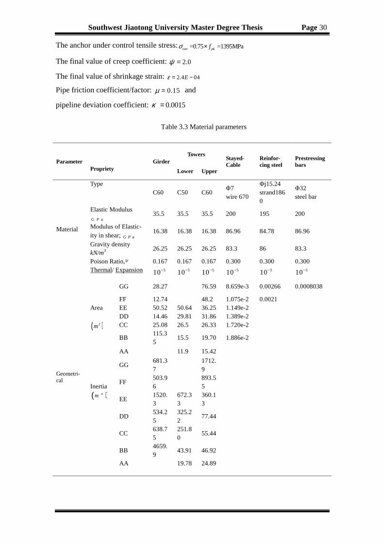
Southwest Jiaotong University Master Degree Thesis Page 30
The anchor under control tensile stress: =0.75 =1395MPacon pkfσ ×
The final value of creep coefficient: 2.0ψ =
The final value of shrinkage strain: 2.4 04Eε = −
Pipe friction coefficient/factor: 0.15µ = and
pipeline deviation coefficient: 0.0015κ =
Table 3.3 Material parameters
Parameter
Propriety Girder
Towers Stayed- Cable
Reinfor-cing steel
Prestressing bars
Lower Upper
Material
Type C60 C50 C60
Φ7 wire 670
Φj15.24 strand1860
Φ32 steel bar
Elastic Modulus
G P a 35.5 35.5 35.5 200 195 200
Modulus of Elastic-ity in shear; G P a
16.38 16.38 16.38 86.96 84.78 86.96
Gravity density kN/m3
26.25 26.25 26.25 83.3 86 83.3
Poison Ratio,ν 0.167 0.167 0.167 0.300 0.300 0.300 Thermal/ Expansion 510−
510−
510−
510−
510−
510−
Geometri-cal
Area
( )2m
GG 28.27 76.59 8.659e-3 0.00266 0.0008038
FF 12.74 48.2 1.075e-2 0.0021 EE 50.52 50.64 36.25 1.149e-2 DD 14.46 29.81 31.86 1.389e-2 CC 25.08 26.5 26.33 1.720e-2
BB 115.35
15.5 19.70 1.886e-2
AA 11.9 15.42
Inertia
( )4m
GG 681.37
1712.9
FF 503.96
893.55
EE 1520.3
672.33
360.13
DD 534.25
325.22
77.44
CC 638.75
251.80
55.44
BB 4659.9
43.91 46.92
AA 19.78 24.89

Southwest Jiaotong University Master Degree Thesis Page 31
The shear modulus of the beam elements was evaluated as:
( )/ 2 1 ;G E ν= + with 0.3ν = . (3.1)
Cables-stayed bridge, a non linear structural system in which the main girder is sup-
ported elastically at the points along its length by inclined cables stays. The Axial stiff-
ness bridge system, changes the non-linearly with cable tension and cable sagging.
Three sources usually maybe cause this geometric nonlinearity such as: the cable sag-
ging; the bending interaction and axial force and the large displacements. Cable rigidity
is characterized by the product eqA E× of the cable cross section area A by the modulus
of elasticity E efficient which is expressed inkN . The equivalent modulus of elasticity
approach was earlier promoted by Ernst (1965) and four decades later by Ren and Peng
(2005). On other hand, three mainly approaches to the nonlinear behavior of cable ele-
ments frequently adopted while modeling cables in cable-stayed bridges and it can be
referred to as the equivalent modulus approach and has been used by several investiga-
tors [16,17,19,26]. Each cable is replaced by one truss element which has the same cable
stiffness. The network of the cable curves representing the ratio /e qE E relying on the
length of the cable horizontal projection, for different values of tensile stress milt. The
cables curves are derived from the Ernst formula.
However, the Modulus of each cable should be adjusted with Ernst formula as:
( )2
311 2
e q
c
EE
lE
γσ
=+
(3.2)
Where:
-eqE is the equivalent elastic modulus of the inclined cables
- E is the cable material effective elastic modulus, which is equal to 2195 /kN mm
-γ is the weight per unit volume of cable steel: 378.5 /kN m
-cl is the horizontal projection length of the cable stay, in m
-σ is the stress of the strand (tension in the cables), in 2/N mm
Midas/civil program has used for cable nonlinear analysis. In the Midas software
program, the cables simulation was adopted to simulate the single cable plane, without
transfer of bending moment and torque. Geometric nonlinear analysis and calculation
of the non-linearity stiffness of the cable unit was accomplished.

Southwest Jiaotong University Master Degree Thesis Page 32
Table 3.4 Summarizes the material properties for the cables
Cable
number
Elastic
modulus
( )GPa
Cable
number
Elastic
modulus
( )GPa
Cable
number
Elastic
modulus
( )GPa
Cable
number
Elastic
modulus
( )GPa
Cable
number
Elastic
modulus
( )GPa
L20' 193.48 L2 194.88 H31 187.83 H10 193.47 H12' 194.58
L19' 193.41 L3 194.82 H30 187.88 H9 193.62 H13' 194.55
L18' 193.31 L4 194.74 H29 187.33 H8 194.25 H14' 194.51
L17' 193.32 L5 194.66 H28 187.4 H7 194.37 H15' 194.46
L16' 193.39 L6 194.57 H27 187.97 H6 194.72 H16' 194.41
L15' 193.46 L7 194.49 H26 188.07 H5 194.78 H17' 194.38
L14' 194.26 L8 194.04 H25 188.2 H4 194.82 H18' 194.38
L13' 194.34 L9 193.74 H24 188.63 H3 194.87 H19' 194.38
L12' 194.42 L10 193.78 H23 188.83 H2 194.92 H20' 194.35
L11' 194.43 L11 193.74 H22 188.97 H1 194.97 H21' 193.87
L10' 194.66 L12 192.77 H21 189.33 H1' 194.97 H22' 193.85
L9' 194.71 L13 192.64 H20 189.55 H2' 194.97 H23' 193.87
L8' 194.74 L14 192.5 H19 189.84 H3' 194.96 H24' 193.8
L7' 194.79 L15 192.29 H18 189.76 H4' 194.95 H25' 193.74
L6' 194.88 L16 192.32 H17 191.89 H5' 194.9 H26' 193.68
L5' 194.9 L17 192.32 H16 191.54 H6' 194.87 H27' 192.18
L4' 194.92 L18 192.1 H15 191.98 H7' 194.85 H28' 192.08
L3' 194.94 L19 192.31 H14 192.15 H8' 194.82 H29' 191.94
L2' 194.95 L20 191.73 H13 192.4 H9' 194.79 H30' 191.96
L1' 194.98 H33 181.73 H12 192.5 H10' 194.77 H31' 191.73
L1 194.95 H32 188.22 H11 193.35 H11' 194.63 H32' 190.46
H33' 191.53

Southwest Jiaotong University Master Degree Thesis Page 33
Load Parameters
Table 3.5 Load parameters
Load Parameters Characteristics
Dead Load
Structure self-weight. A permanent load include the main beam self-weight and
heavy cross pressure in order to maintain the asymmetrical CSB with three spans
balanced side. PC; RC unit weight 3 26 /kN mγ = ; the side spans ballast550 /kN m. By
uniform load applied on the main beam side cross-unit.
Secondary Load
The pavement thickness 80mm, 3 25 /kN mγ = ; asphalt concrete 70 mm,
3 24 /kN mγ = . The crash barrier 8 /kN mγ = per side sidewalk structure18 /kN m , central
green belt and cable-stayed isolation with 16kN / m; a total of two dead load
of200 / kN m are uniformly distributed load applied on the main beam unit. Asphalt
pavement, guardrail etc. in total: 91.3 /kN m
Pedestrian Load Press 4kN/m2 load range for sidewalks and slow lane 2m wide, uniform load
24 /kN m applied to the main beam unit.
Live/Imposed Load
Bidirectional four lane road, levelⅠ: lane load: uniformed distributed load 10.5 /KN m= ,concentrated load 360kN= 。
Impact coefficient (factor) 0.05u=
( ) 6 0 2 0( )0 4 .in J T G D p d f−公 路 桥 涵 设 计 通 用 规 范
Temperature Load Average annual temperature: 18.17℃; closure temperature: 15~25℃。Concrete
temperature annual maximum increase: 18.5℃, concrete temperature annual maximum decrease: 18.5℃。Temperature difference between girder and cable: 10℃
,Gradient temperature difference of the girder, the value based on 100mm depth of bituminous pavement.
Wind Load
Hundred-year wind speed value in Chongqing Fuling City: V10=24.4m/s The combination of wind and the car load speed by deck, with the consideration of longi-tudinal wind effect of the main tower.
Support Settlement Main bridge tower settlement value 1.0cm for main tower, 0.5cm for side pier
Ship impact Force According to the specification, pier boat collision force to take cross-bridge to 400kN, Fuling, to take 350kN.
Earthquake Load Basic design earthquake acceleration value of 0.15g, and the design characteristic period of 0.35s.

Southwest Jiaotong University Master Degree Thesis Page 34
Load combination
According to the “General Code for Design of highway bridges and culverts JTG
D60-2004” [43], basic combinations role in the short/long-term effects of a combination
of the standard value combinations, each load combination selected coefficients are
calculated according to the specifications. Before the construction of sub and super-
structure part of the bridge construction and the finally completed bridge deck system,
traffic engineering and other ancillary works must be done. Therefore, it is known that
the safety of the structure depends on the adequate load-bearing capacity establishment
and the prestress effect must be included as well as those due to creep and shrinkage of
the temperature changing and the settlement.
Load combination and definition:
It is well-known that design stresses should be calculated for the most severe com-
binations cases of loads and forces. Where, the load combinations are mostly consid-
ered important for the bridge structure adequacy checking.
Temperature combination 1: STI + PTDCG + TIGR + TIOST
With:
STI- System Temperature Increase; PTDCG- Positive Temperature Difference be-
tween Cable and Girder; TIGR- Temperature Increase in Girder Roof; TIOST- Tem-
perature Increase in one side of Tower and the Temperature combination 2:STD +
NTDCG + TDGR
With:
STD- System Temperature Decrease; NTDCG- Negative Temperature Difference
between Cable-Girder and TDGR- Temperature Decrease in Girder Roof
Load combinationI:DL+LL+DSF
Load combinationII :Load combinationI+Wind Load +Temperature combination 1
Load combinationIII:Load combinationI+Wind Load +Temperature combination 2
Load combinationIV:DL+ Overspread Pedestrian Load + Wind Load Temperature
With:
DL- Dead Load; LL- Live Load (include vehicle load and pedestrian load) and DSF-
Differential Settlement of the Foundation
Combination 1
Load combination V:DL+ Overspread Pedestrian Load + WL+ Temperature Load

Southwest Jiaotong University Master Degree Thesis Page 35
We always take the load combinationI as a main Load combination and the rest ad-
ditional load combination in the CSB construction control.
3.2 CONSTRUCTION PROCESS ANALYSIS
3.2.1 Construction stages definition
In order to perfect the design of a CSB and to analyse the whole structure, a con-
struction stage analysis must be conducted. We firstly simulated the whole model con-
struction process with the following purposes:
♦ Search for each construction step, the required tension forces in the cable stays
♦ Geometry of the girder fabrication Specification
♦ The segment of the girder elevation setting
♦ Structural deformation computation at each construction stage
♦ Check the stresses in the pylon girder and sections
The reasonable construction should be design and investigate apart the stability of
each stage. Different erection methods are used, and the structural system can greatly
change according to the type of erection. Sometimes, during the construction process
system, a change can be related in a crucial condition for the structure compared to that
of the last phase. To that purpose, an accurate CS analysis should be performing by
checking and reviewing the stresses in the towers, the girder and the cables. So to cal-
culate the deformation and stress state, we should considered the influence of shrinkage
and creep by the state of the structure analysis method. Furthermore, the girder geomet-
ric profile is also very important during the structure construction. It must be ensured
that both cantilever ends meet smoothly together in the structure last construction stage
to avoid serious problems. It’s noted that, during the construction process varied the
girder elevation and the internal forces of the structure, which related to the building of
the bridge segments by a few components, the heavy lifting operations (make in ad-
vance segments) and the erection equipment (different positions of structure).
To pull off a construction stage analysis, we should define the CS by activating or
deactivating if need be, the segment of the main girder, cables, boundary conditions,
loads by paying attention to their effect and the change on the structure.
In our Thesis, the asymmetric cable-stayed bridges with unequal pylons construction
process were being divided in 80 stages of construction, (see Table 3.6).

Southwest Jiaotong University Master Degree Thesis Page 36
Table 3.6 Construction stages/phases definitions
Number
Construction contents
Time (days)
CS1 Activate Tower1 and Tower2 300
CS42 Activate Seg.No0 of Tower2, and its pre-stress tendon , Wet concrete weigh, diaphragm,
derrick cram1
10
Temp1 Deactivate Wet concrete weight of Seg.N0.1 0.1
CS43 Activate Seg.No1 of Tower2, and its pre-stress tendon , Diaphragm, Wet concrete
weight, Tendon Cable H1 and H’1
10
CS43-1 Activate Derrick cram2, Wet concrete weight of Seg.N0.2, Deactivate derrick cram1 9
TEMP2 Deactivate Wet concrete weight of Seg.N0.2 0.1
CS44 Activate Seg.No2 of Tower2, and its Pre-stress tendon , Diaphragm, Tendon Cable H2
and H’2
1
CS44-1 Activate Derrick cram3, Wet concrete weight of Seg.No.3, Deactivate derrick cram2 9
…… …… ……
CS52-1 Activate derrick cram11, Wet concrete weight of Seg.No.11, First 10 Balance weight
,Adjust Cable force H7’, Deactivate derrick cram10
9
TEMP11 Deactivate Wet concrete weight of Seg.N0.11 0.1
CS53 Activate Seg.No12 of Tower2, Diaphragm, Tendon Cable H11 and H’11, its Pre-stress
tendon
1
CS53-1 Activate derrick cram12, Wet concrete weight of Seg.No.11, Balance weight H11, Deac-
tivate derrick cram11
9
TEMP12 Deactivate Wet concrete weight of Seg.N0.12 0.1
CS54 Activate Seg.No12 of Tower2, Seg.No0 of Tower1, Diaphragms, Tendon Cable H11 and
H’11, its Pre-stress tendon
1
CS54A Activate derrick cram13, Wet concrete weight of Seg.No.13,Deactivate derrick cram12 9
TEMP13 Deactivate Balance weight H12, Wet concrete weight of Seg.N0.13 0.1
CS55 Activate Seg.No13 of Tower2, Tendon Cable H12 and H’12,Seg.No1 of Tower1,
Pre-stress tendon , Diaphragms
1
CS55A Activate derrick cram14, Wet concrete weight of Seg.No.14, Deactivate derrick cram13 9
TEMP14 Deactivate Balance weight H13, Wet concrete weight of Seg.N0.14 0.1
CS56 Activate Seg.No14 of Tower2, Tendon Cable H13 and H’13, Seg.No2 of Tower1,
Tendon Cable L1 and L’1, Pre-stress tendon , Diaphragms
1
CS56A Activate derrick cram15, Wet concrete weight of Seg.No.15, Deactivate derrick cram14 9
TEMP15 Deactivate Counter weight H14, Wet concrete weight of Seg.N0.15 0.1
CS57 Activate Seg.No15 of Tower2, Tendon Cable H14 and H’14, Seg.No3 of Tower1,
Tendon Cable L2 and L’2, Pre-stress tendon , Diaphragms
1
CS57A, Activate derrick cram16, Wet concrete weight of Seg.No.16, Deactivate derrick cram16 9
TEMP16 Deactivate Balance weight H15, Wet concrete weight of Seg.N0.16 0.1

Southwest Jiaotong University Master Degree Thesis Page 37
CS58 Activate Seg.No16 of Tower2, Tendon Cable H15 and H’15, Seg.No4 of Tower1,
Tendon Cable L3 and L’3, Pre-stress tendon , Diaphragms
1
CS58A Activate derrick cram17, Wet concrete weight of Seg.No.17, Deactivate derrick cram17 9
TEMP17 Deactivate Balance weight H16, Wet concrete weight of Seg.N0.17 0.1
CS59 Activate Seg.No17 of Tower2, Tendon Cable H16 and H’16, Seg.No5 of Tower1,
Tendon Cable L4 and L’4, Pre-stress tendon , Diaphragms
1
CS59A Activate derrick cram18, Wet concrete weight of Seg.No.18, Lower tower adjusted force
and Balance weight of tower 1, Deactivate derrick cram17
9
TEMP18 Deactivate Balance weight H17, Wet concrete weight of Seg.N0.18 0.1
CS60 Activate Seg.No18 of Tower2, Tendon Cable H17 and H’17, Seg.No6 of Tower1,
Tendon Cable L5 and L’5, Diaphragms
1
…… …… ……
CS64A Activate derrick cram23, Wet concrete weight of Seg.No.23, Deactivate derrick cram22 9
TEMP23 Deactivate Balance weight H22, Wet concrete weight of Seg.N0.23 0.1
CS65 Activate Seg.No23 of Tower2, Tendon Cable H22 and H’22, Seg.No11 of Tower1,
Tendon Cable L10 and L’10, Diaphragms, Pre-stress, Temporary Balance weight 23’
and construction Balance weight 12 in east side, Balance weight H23’
1
CS65A Activate derrick cram24, Wet concrete weight of Seg.No.24, Temporary Balance weight
23, construction counter weight 23; Deactivate derrick cram23, Temporary Balance
weight 23’, Balance weight H23’
9
TEMP24 Deactivate Wet concrete weight of Seg.N0.24 0.1
CS66 Activate Seg.No24 of Tower2, Tendon Cable H23 and H’23, Seg.No12 of Tower1,
Tendon Cable L11 and L’11, Diaphragms, Pre-stress, Temporary Balance weight 24’
and construction Balance weight 13 in east side, Balance weight H24’
1
CS66A Activate derrick cram25, Wet concrete weight of Seg.No.25, Temporary Balance weight
24, Balance weight 24; Deactivate derrick cram24, Temporary Balance weight 24’, Bal-
ance weight H24’
9
TEMP25 Deactivate Wet concrete weight of Seg.N0.25 0.1
CS67 Activate Seg.No25 of Tower2, Tendon Cable H24 and H’24, Seg.No13 of Tower1,
Tendon Cable L12 and L’12, Diaphragms, Pre-stress, Temporary Balance weight 25’,
counter weight H25’
1
ACS2 Activate Patch Tendon H8/9/10’ 2
CS67A Activate derrick cram26, Wet concrete weight of Seg.No.26, Temporary Balance weight
25, Balance weight 25; Deactivate derrick cram25, Temporary Balance weight 24’, Bal-
ance weight H24’
9
TEMP26 Deactivate Wet concrete weight of Seg.N0.26 0.1
CS68 Activate Seg.No26 of Tower2, Tendon Cable H25 and H’25, Seg.No14 of Tower1,
Tendon Cable L13 and L’13, Diaphragms, Pre-stress, Temporary Balance weight 25’,
Balance weight H25’
1
CS68A Activate derrick cram27, Wet concrete weight of Seg.No.27, Temporary Balance weight 9

Southwest Jiaotong University Master Degree Thesis Page 38
26, Balance weight 26; Deactivate derrick cram26, Temporary Balance weight 25’, Bal-
ance weight H25’
TEMP27 Deactivate Wet concrete weight of Seg.N0.27 0.1
CS69 Activate Seg.No27 of Tower2, Tendon Cable H26 and H’26, Seg.No15 of Tower1,
Tendon Cable L14 and L’14, Diaphragms, Pre-stress, Temporary Balance weight 26’,
Balance weight H27’
1
CS69A Activate derrick cram28, Wet concrete weight of Seg.No.28, Temporary Balance weight
27, Balance weight 27; Deactivate derrick cram27, Temporary Balance weight 26’, Bal-
ance weight H26’
9
TEMP28 Deactivate Wet concrete weight of Seg.N0.28 0.1
CS70 Activate Seg.No28 of Tower2, Tendon Cable H27 and H’27, Seg.No16 of Tower1,
Tendon Cable L15 and L’15, Diaphragms, Pre-stress, Temporary Balance weight 14 and
15, Balance weight H27’, Deactivate Temporary Balance weight 14’
1
CS70A Activate derrick cram29, Wet concrete weight of Seg.No.29, Balance weight H28 and
L15, Deactivate derrick cram28, Temporary Balance weight 28’,
9
TEMP29 Deactivate Wet concrete weight of Seg.N0.29 0.1
CS71 Activate Seg.No29 of Tower2, Tendon Cable H28 and H’28, Seg.No17 of Tower1,
Tendon Cable L16 and L’16, Diaphragms, Pre-stress, Temporary Balance weight 15 ,
Balance weight H29’, Deactivate Temporary Balance weight 15’
1
CS71A Activate derrick cram30, Wet concrete weight of Seg.No.30, Balance weight H29 and
L16, Deactivate derrick cram29, Temporary Balance weight 29’
9
TEMP30 Deactivate Wet concrete weight of Seg.N0.30 0.1
CS72 Activate Seg.No30 of Tower2, Tendon Cable H29 and H’29, Seg.No18 of Tower1,
Tendon Cable L17 and L’17, Diaphragms, Pre-stress, counter weight H30’, Deactivate
Temporary Balance weight 15’
1
CS72A Activate derrick cram31, Wet concrete weight of Seg.No.31, Balance weight H30 and
L17, Deactivate derrick cram30, Temporary counter weight 30’
9
TEMP31 Deactivate Wet concrete weight of Seg.N0.31 0.1
CS73 Activate Seg.No31 of Tower2, Tendon Cable H30 and H’30, Seg.No19 of Tower1,
Tendon Cable L18 and L’18, Diaphragms, Pre-stress, Balance weight H31’,
1
CS73A Activate derrick cram32, Wet concrete weight of Seg.No.32, Balance weight H31 and
L18, Deactivate derrick cram31, Temporary Balance weight 31’
9
TEMP32 Deactivate Wet concrete weight of Seg.N0.32 0.1
CS74 Activate Seg.No32 of Tower2, Tendon Cable H31 and H’31, Seg.No20 of Tower1,
Tendon Cable L19 and L’19, Diaphragms, Pre-stress, Balance weight H32’, Temporary
support and side pier
1
CS74-00 Activate derrick cram 1, Balance weight H33, H32, L20 and L19, Deactivate Temporary
Balance weight 13, 14, 15, 23, 24,25,26, and H32’
4
CS74-0 Activate side span closure stiff skeleton 3
CS74A Activate side closure parts 3

Southwest Jiaotong University Master Degree Thesis Page 39
3.2.2 The maximum double cantilever stage
The maximum double cantilever phase of the long-span cable-stayed bridge is at all
time the most disadvantageous state for the wind resisting. Therefore the stability
checking calculation is required to secure the bridge safety.
Figure 3.8 Stress of the girder and tower upper edge
Figure 3.9 Stress of the girder and tower lower edge
CS74B Activate derrick cram33, Wet concrete weight of Seg.No.33, Deactivate derrick cram32 4
TEMP33 Deactivate Wet concrete weight of Seg.N0.33 0.1
CS75 Activate Seg.No33 of Tower2, Tendon Cable H32 and H’32,Seg.No20 of Tower1,
Tendon Cable L19 and L’19, Diaphragms, Pre-stress, Balance weight H32’, Temporary
support and side pier
2
CS76 Activate Key Segment, Deactivate derrick cram1, and all the closure derrick crams 7
CS77 Activate the middle and sides pre-stress 7
CS78 Activate the sides span temporary supports, all cable adjusted force 8
CS79 Activate secondary dead load 8
CS80 Operation stage 1100

Southwest Jiaotong University Master Degree Thesis Page 40
Figure 3.10 Stress of the cables
The maximum and minimum stresses are respectively 633.12MPa (Cable H’9 and
H’10) and 348.89MPa (Cable L20, L’20 and H33). The detail of the displacement of
both towers top can be seen in Figure 3.26. The above figures show that the stresses of
all the members sections considering can meet the requirements of corresponding de-
sign and construction code at each phase. The Wujiang Bridge state stress is reasonable
and the girder's level smoothness can meet the requirements of the bridge design and
code. Therefore, we can say that the structure construction quality is showed to have
been under a good control.
3.2.3 Stress and displacement analysis in construction
The diagrams below explain the displacement and stresses of towers and girder at
different construction stages.
Figure 3.11 Displacement of towers top at different construction stages

Southwest Jiaotong University Master Degree Thesis Page 41
Figure 3.12 Stresses in Seg.No.0 of girder at different construction stages
Figure 3.13 Stresses of both towers bottom section at different construction stages
As the Figure 3.11 shows, the Tower 1 maximum and minimum displacement are
respectively 113.7mm; -138.3 mm and CS 61; CS 76 are their correspondant stages.
The Tower 2 maximum and minimum displacement are respectively 189.1mm; -
140.34mm and CS 76; CS 52 are their correspondant stages.
The Figure 3.12 shows that the Lower Tower minimum and maximum stress are re-
spectively 0.75; 5.75 and CS 54; CS 79 are their correspondant stages. Higher Tower
minimum and maximum stress are respectively 1.25; 6.75 and CS1; CS79 are their
correspondant stages.
For the Figure 3.13, the Lower Tower minimum and maximum stress are respec-
tively 2.5; 7.5 and CS 1; CS 79 are their correspondant stages. The Higher Tower
minimum and maximum stress are respectively 2.9 ; 7.75 and CS1; CS79 are their cor-
respondant stages.

Southwest Jiaotong University Master Degree Thesis Page 42
3.2.4 Cable force on construction and finished dead state
In all cable-stayed bridges system, the most important and basic element is the stay-
cable. Therefore more details on it technology with an emphasis on the corrosion pro-
tection are given by Ito [31]. The cable force is directly related to the main beam of the
linear structure of the internal forces. In the bridge construction process state, attention
is specially given to their tension on construction and finished dead state. The process
is described in 3.2.1 according to the construction phase, which can be calculated each
cable-stayed construction tension. The operational phase of the completed bridge
shows, according to a different bridge state load combination, that the stress are less
than the allowable stress 813.6MPa specification (less than =0.75 =1395MPacon pkfσ × ) and
the operational phase cable stress amplitude is less than the product limit 200 MPa.
Therefore, it is a necessity to simulate and to correct the parameter error if need be in
the construction state in order to meet the design requirements. The permanent state of
stress in a CSB structure subjected to dead load is determined by the tension forces in
the cable stays. Therefore cable tension can be chosen in ordr to eliminated or to reduce
as much as possible the bending moments in the pylons and girders. So the pylon and
deck would be principally under compression under the dead loads as well [41, 43].
Table 3.7 Construction and finished cable force
Cable No.
Closure state without sec-ondary load (KN)
Finished state with secon-dary load (KN)
Cable No.
Closure state without sec-ondary load (KN)
Finished state with secon-dary load (KN)
L20' 4657.49 6905.41 H20 5107.61 6306.09 L19' 5927.30 7966.87 H19 4812.83 6030.30
L18' 5635.71 7465.37 H18 4806.28 6034.56
L17' 5511.73 6927.90 H17 4445.74 5492.10
L16' 5807.95 7153.34 H16 4215.49 5258.03
L15' 5803.23 7080.36 H15 4154.34 5190.89
L14' 5869.81 6836.45 H14 4043.70 5067.75
L13' 5630.07 6547.09 H13 3923.24 4926.98
L12' 5130.67 6000.10 H12 3781.49 4755.59
L11' 5232.50 6056.29 H11 3788.83 4616.69
L10' 4901.07 5558.15 H10 3876.67 4661.55
L9' 5078.26 5699.88 H9 3723.37 4455.54
L8' 4995.92 5582.07 H8 3386.44 4097.68
L7' 5003.73 5620.40 H7 3058.44 3708.32
L6' 4944.08 5451.68 H6 3125.71 3704.75
L5' 4687.38 5156.30 H5 3298.84 3789.07
L4' 4152.39 4577.57 H4 3437.42 3825.63
L3' 4081.77 4455.45 H3 3283.92 3562.30

Southwest Jiaotong University Master Degree Thesis Page 43
3.3 COMPLETED STATE ANALYSIS
3.3.1 Analysis of distributed load effects
(A)-Dead load effects
Constant weight of the structure member, including the structure itself and its layers.
Dead load effect is important to be considered in term of structure break up. Conse-
quently, the changing effect of dead loads such as displacements and stress at com-
pleted stage was discussed. The dead load effects on the upper, lower flange of tower
and girder were also obtained as shown the following figures.
L2' 3935.08 4335.87 H2 4096.81 4272.33
L1' 4237.64 4653.23 H1 5371.96 5356.60
L1 4792.66 5016.97 H1' 3949.08 4473.03
L2 4244.29 4557.74 H2' 3611.63 3974.56
L3 3804.72 4272.99 H3' 4121.78 4472.52
L4 3816.95 4426.34 H4' 3821.88 4213.96
L5 4299.26 5029.26 H5' 3789.76 4269.11
L6 4385.81 5214.10 H6' 3816.96 4332.17
L7 4398.41 5307.89 H7' 3875.29 4257.89
L8 4326.27 5383.84 H8' 5231.12 5637.28
L9 4549.95 5568.35 H9' 5358.64 5785.66
L10 4305.29 5370.27 H10' 5448.24 5894.02
L11 4663.36 5764.06 H11' 5070.74 5595.46
L12 4564.18 5873.34 H12' 5153.27 5695.66
L13 4883.19 6204.96 H13' 5181.93 5740.18
L14 5100.78 6419.00 H14' 5191.45 5766.29
L15 5193.75 6492.62 H15' 5321.60 5912.61
L16 5159.12 6432.90 H16' 5014.88 5621.12
L17 5094.33 6337.32 H17' 4797.51 5418.41
L18 5031.89 6336.78 H18' 4970.63 5605.90
L19 5310.79 6772.56 H19' 4652.31 5301.74
L20 3905.80 5313.92 H20' 4735.64 5399.12
H33 3674.39 4386.85 H21' 4873.74 5678.04
H32 5022.10 5838.11 H22' 6252.92 7074.72
H31 5023.19 5927.96 H23' 5847.11 6687.31
H30 4953.18 5945.22 H24' 6265.20 7124.86
H29 5173.14 6247.17 H25' 6366.49 7247.07
H28 5245.08 6399.28 H26' 6090.39 6993.28
H27 5497.54 6530.01 H27' 5947.52 7105.23
H26 5538.13 6642.69 H28' 6065.69 7254.65
H25 5491.84 6665.29 H29' 5440.30 6662.30
H24 5440.02 6677.52 H30' 5530.06 6787.68
H23 5103.63 6393.59 H31' 5663.68 7707.26
H22 5075.26 6409.84 H32' 5792.20 8147.28 H21 5349.73 6720.08 H33' 5726.99 8240.40

Southwest Jiaotong University Master Degree Thesis Page 44
Figure 3.14 Stresses at the upper flange of tower and girder on dead load at completed stage
Figure 3.15 Stresses at the lower edge of tower and girder on dead load at completed stage
Figure 3.16 Stressed in all cables on dead load at completed stage
Figure 3.17 Structure displacement on dead load at completed stage (unit: cm)

Southwest Jiaotong University Master Degree Thesis Page 45
Table 3.8 Cable forces and stresses on dead load at completed stage with creep and shrinkage
of 10 years concrete
(2)-Live Load effects (Pedestrian load and vehicle load-City A)
The live load effects on different layers of the structure were obtained by adding the
maximum effects from various the moving live load (truck) cases.
Cable Force (kN) Stress
(MPa) Cable Force (kN)
Stress
(MPa) Cable Force (kN)
Stress
(MPa)
L20' 7075.20 485.10 L17 6339.91 547.30 H1 5264.10 540.70
L19' 8109.76 556.00 L18 6331.70 546.60 H1' 4361.77 508.20
L18' 7580.27 519.70 L19 6758.13 583.40 H2' 3890.72 540.60
L17' 7019.21 481.20 L20 5288.20 456.50 H3' 4399.16 611.30
L16' 7220.52 495.00 H33 4268.37 368.50 H4' 4150.61 576.70
L15' 7125.43 488.50 H32 5731.24 494.80 H5' 4204.60 489.90
L14' 6856.72 591.90 H31 5835.47 503.80 H6' 4277.60 498.40
L13' 6553.24 565.70 H30 5865.35 506.30 H7' 4212.24 490.80
L12' 5993.42 517.40 H29 6178.50 533.40 H8' 5599.69 652.50
L11' 6037.85 521.20 H28 6340.05 547.30 H9' 5755.57 670.70
L10' 5533.51 568.30 H27 6479.12 559.30 H10' 5871.00 684.10
L9' 5666.11 581.90 H26 6599.58 569.70 H11' 5576.88 572.80
L8' 5538.85 568.90 H25 6629.67 572.30 H12' 5683.82 583.80
L7' 5567.00 571.80 H24 6648.87 574.00 H13' 5734.67 589.00
L6' 5394.25 628.60 H23 6370.02 549.90 H14' 5766.08 592.20
L5' 5087.19 592.80 H22 6390.73 551.70 H15' 5916.77 607.70
L4' 4494.54 523.70 H21 6704.08 578.70 H16' 5628.39 578.10
L3' 4355.53 507.50 H20 6293.46 543.30 H17' 5427.55 557.40
L2' 4215.80 491.20 H19 6020.36 519.70 H18' 5615.68 576.80
L1' 4511.62 525.70 H18 6028.02 520.40 H19' 5311.04 545.50
L1 4947.73 508.20 H17 5489.04 563.80 H20' 5406.94 555.30
L2 4530.24 527.90 H16 5258.20 540.00 H21' 5684.64 490.70
L3 4261.73 496.60 H15 5193.98 533.40 H22' 7078.07 611.00
L4 4423.21 515.40 H14 5073.98 521.10 H23' 6687.26 577.30
L5 5029.28 586.00 H13 4935.43 506.90 H24' 7121.76 614.80
L6 5214.00 607.60 H12 4765.44 489.40 H25' 7241.44 625.10
L7 5308.58 618.60 H11 4626.12 539.00 H26' 6985.70 603.10
L8 5386.58 553.20 H10 4671.33 544.30 H27' 7094.06 486.40
L9 5574.83 572.60 H9 4465.45 520.30 H28' 7242.62 496.60
L10 5380.35 552.60 H8 4105.99 570.50 H29' 6650.32 456.00
L11 5778.37 593.50 H7 3715.55 516.30 H30' 6776.31 464.60
L12 5892.89 508.70 H6 3709.31 515.40 H31' 7696.55 527.70
L13 6226.23 537.50 H5 3787.46 526.30 H32' 8136.52 502.20
L14 6438.70 555.80 H4 3812.92 529.80 H33' 8230.56 508.00
L15 6507.25 561.80 H3 3534.32 491.10
L16 6441.88 556.10 H2 4226.26 587.30

Southwest Jiaotong University Master Degree Thesis Page 46
(A)-Stress
Figure 3.18 Stresses at the upper flange of tower and girder on live load at completed stage
Figure 3.19 Stresses at upper flange of tower and girder on dead and live load at completed
stage
As the both figures show, the maximum tensile stress of the edge of the main beam
under live load is 5.25MPa and the maximum compressive stress 4.71MPa. The maxi-
mum tensile stress at the edge of girder under dead and live load is 1.02MPa while the
maximum compressive stress is 16.05MPa. The maximum tensile stress appears in
place near the cross-bearing. Therefore, the two sides across the main beam near the
riverbank edge should be supplemented with some of the pre-stressing tendons.
Figure 3.20 Stress amplitude on live load at completed stage

Southwest Jiaotong University Master Degree Thesis Page 47
The maximum amplitude of cable stress under live load (City A + pedestrian) is
80.66MPA and the minimum is -13.79MPA, which are both less than 200MPa in speci-
fication.
(B)- Displacement
Figure 3.21 Maximum displacement under vehicle load -City A
Figure 3.22 Minimum displacement under vehicle load -City A
Figure 3.23 Displacement under pedestrian load

Southwest Jiaotong University Master Degree Thesis Page 48
Figure 3.24 Action of the main beam displacement under live load (Pedestrian+ City A)
From the Figures ( 21 to 24 ), the girder stiffness under the live load (pedestrian + city
A) is =33.42/34000=1/1017.4 < 1/500, which can meets the specification.
(C)- Distributed effects under all kinds of load
Table 3.9 Most unfavorable stress in control section under all kinds of loads (unit: MPa)
Section posi-tion
City-A pedes-trian
Fini-shed state
Over-all T in-
crease
Overall T de-crease
Sun shine T
in-crease
Sun-shine T
de-crease
Wind load
current water
loading
ship's im-pact force
Max Min Left girder
upper section of LT
2.51 -1.66 0.00 -4.78 -0.58 0.59 -1.07 0.52 0.66 -0.07 -0.09
Left girder lower section
of LT 1.16 -3.12 -0.14 -6.70 1.06 -1.08 0.65 -0.32 -0.25 0.03 0.01
Right girder Upper section
of LT 2.34 -1.29 0.34 -4.53 0.77 -0.79 -0.83 0.40 0.98 -0.05 -0.08
Right girder lower section
of LT 0.77 -3.36 -0.77 -7.18 -1.64 1.67 0.20 -0.10 -0.37 0.02 0.07
Left point of upper section
of LT 0.79 -2.06 -0.47 -10.30 -1.48 1.51 -0.16 0.08 1.34 0.00 0.03
Right point of upper section
of LT 1.24 -0.94 0.23 -10.30 1.66 -1.69 0.17 -0.08 -1.34 0.00 -0.03
Left point of lower section
of LT 3.32 -4.25 -0.57 -7.58 -1.56 1.59 -0.26 0.13 0.82 0.00 -0.04
Right point of lower section
of LT 3.66 -3.53 0.38 -6.26 1.61 -1.64 0.27 -0.13 -0.82 0.00 0.04
left girder Upper section
of HT 2.07 -1.07 0.32 -6.56 0.48 -0.49 -0.86 0.41 1.02 -0.03 0.01

Southwest Jiaotong University Master Degree Thesis Page 49
3.3.2 Effect analysis of load combination
Table 3.10 Load combination
left girder lower section
of HT 0.68 -3.04 -0.71 -6.81 -1.04 1.06 0.17 -0.09 -0.38 0.01 0.02
Right girder Upper section
of HT 2.21 -1.82 0.00 -3.82 -0.13 0.13 -1.03 0.50 0.48 -0.07 -0.03
Right girder lower section
of HT 1.42 -2.57 -0.15 -10.7 0.27 -0.27 0.48 -0.24 -0.18 0.03 0.01
Left point of upper section
of HT 1.58 0.96 0.27 -6.76 0.94 -0.96 0.14 -0.07 3.09 0.00 -0.01
Right point of upper section
of HT -1.11 -2.12 -0.46 -12.3 -0.85 0.87 -0.13 0.06 -3.09 0.00 0.01
Left point of lower section
LT 3.16 -2.84 0.28 -9.69 0.62 -0.63 0.15 -0.07 1.56 0.00 0.03
Right point of lower section
of HT 2.65 -3.78 -0.53 -11.70 -0.58 0.59 -0.14 0.07 -1.56 0.00 -0.03
left section of LT bottom
2.26 -2.04 0.18 -9.14 3.71 -3.78 0.35 -0.17 3.17 0.49 0.53
Right section of LT bottom
1.86 -2.71 -0.35 -5.86 -3.66 3.73 -0.34 0.17 -3.17 -0.49 -0.53
Left section of HT bottom
1.30 -1.43 -0.14 -6.52 -2.10 2.14 -0.18 0.09 3.31 0.50 0.28
Right section of HT bot-
tom 1.21 -1.56 -0.01 -8.92 2.13 -2.17 0.19 -0.09 -3.31 -0.50 -0.28
Key seg. Upper point in mid-span
0.80 -1.84 -0.24 -5.69 -0.40 0.41 -0.54 0.26 -1.58 -0.05 -0.03
Lower point of key seg. in
mid-span 3.19 -0.94 0.45 -6.46 -0.12 0.12 0.54 -0.27 0.59 0.02 0.06
combination Loads involved in combination
Combination I Dead load+ City-A+ pedestrian
Combination II Dead load+ City-A+ pedestrian+ overall temperature increase
Combination III Dead load+ City-A+ pedestrian+ overall temperature decrease
Combination IV Dead load+ City-A+ pedestrian+ + overall temperature increase + sun-
shine temperature difference

Southwest Jiaotong University Master Degree Thesis Page 50
Table 3.11 Most unfavorable stress in control section under the load combination above (unit: MPa)
Combination V Dead load+ City-A++ overall temperature increase+ pedestrian+ sun-
shine negative temperature difference Combination VI Dead load+ City-A+ pedestrian+ + overall temperature decrease + sun-
shine temperature difference Combination VII Dead load+ City-A++ overall temperature decrease+ pedestrian+ sun-
shine negative temperature difference Combination VIII Dead load + wind load
Combination IX Dead load + wind load+ current water load
Combination X Dead load + ship's impact force
Load Combination I Combination II Combination III Combination IV
max min max min max min max min
Upper section of left girder in LT -2.27 -6.44 -2.85 -7.02 -1.68 -5.85 -3.92 -8.09
Lower section of left girder in LT -5.68 -9.96 -4.62 -8.90 -6.76 -11.04 -3.97 -8.25
Upper section of right girder in LT -1.85 -5.48 -1.08 -4.71 -2.63 -6.26 -1.91 -5.54
Lower section of right girder in LT -7.18 -11.31 -8.82 -12.95 -5.51 -9.64 -8.62 -12.75
Left HT section in LT -9.98 -12.83 -11.46 -14.31 -8.47 -11.32 -11.62 -14.47
Right HT section in LT -8.83 -11.01 -7.17 -9.35 -10.52 -12.70 -7.01 -9.19
left HT section in LT -4.83 -12.40 -6.39 -13.96 -3.24 -10.81 -6.65 -14.22
Right LT section in LT -2.22 -9.41 -0.61 -7.80 -3.86 -11.05 -0.34 -7.53
Upper section of left girder in HT -4.17 -7.31 -3.69 -6.83 -4.66 -7.80 -4.55 -7.69
lower section of left girder in HT -6.85 -10.56 -7.89 -11.60 -5.79 -9.50 -7.71 -11.43
Upper section of right girder in HT -1.61 -5.64 -1.74 -5.77 -1.48 -5.51 -2.77 -6.80
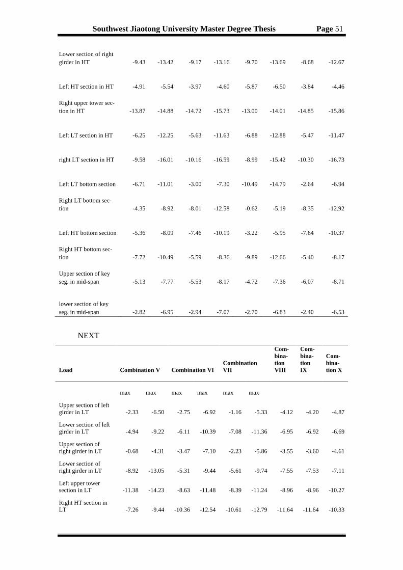
Southwest Jiaotong University Master Degree Thesis Page 51
NEXT
Lower section of right girder in HT -9.43 -13.42 -9.17 -13.16 -9.70 -13.69 -8.68 -12.67
Left HT section in HT -4.91 -5.54 -3.97 -4.60 -5.87 -6.50 -3.84 -4.46
Right upper tower sec-tion in HT -13.87 -14.88 -14.72 -15.73 -13.00 -14.01 -14.85 -15.86
Left LT section in HT -6.25 -12.25 -5.63 -11.63 -6.88 -12.88 -5.47 -11.47
right LT section in HT -9.58 -16.01 -10.16 -16.59 -8.99 -15.42 -10.30 -16.73
Left LT bottom section -6.71 -11.01 -3.00 -7.30 -10.49 -14.79 -2.64 -6.94
Right LT bottom sec-tion -4.35 -8.92 -8.01 -12.58 -0.62 -5.19 -8.35 -12.92
Left HT bottom section -5.36 -8.09 -7.46 -10.19 -3.22 -5.95 -7.64 -10.37
Right HT bottom sec-tion -7.72 -10.49 -5.59 -8.36 -9.89 -12.66 -5.40 -8.17
Upper section of key seg. in mid-span -5.13 -7.77 -5.53 -8.17 -4.72 -7.36 -6.07 -8.71
lower section of key seg. in mid-span -2.82 -6.95 -2.94 -7.07 -2.70 -6.83 -2.40 -6.53
Load Combination V Combination VI Combination VII
Com-bina-tion VIII
Com-bina-tion IX
Com-bina-tion X
max max max max max max
Upper section of left girder in LT -2.33 -6.50 -2.75 -6.92 -1.16 -5.33 -4.12 -4.20 -4.87
Lower section of left girder in LT -4.94 -9.22 -6.11 -10.39 -7.08 -11.36 -6.95 -6.92 -6.69
Upper section of right girder in LT -0.68 -4.31 -3.47 -7.10 -2.23 -5.86 -3.55 -3.60 -4.61
Lower section of right girder in LT -8.92 -13.05 -5.31 -9.44 -5.61 -9.74 -7.55 -7.53 -7.11
Left upper tower section in LT -11.38 -14.23 -8.63 -11.48 -8.39 -11.24 -8.96 -8.96 -10.27
Right HT section in LT -7.26 -9.44 -10.36 -12.54 -10.61 -12.79 -11.64 -11.64 -10.33

Southwest Jiaotong University Master Degree Thesis Page 52
3.3.3 Limited state analysis
Developed since many years ago, it was widely integrated in design and codes in
many countries were the structure constructions are developed. This pay attention to the
different bridges structure conditions life. Attention is also give for two limit states:
(1)-Stress analysis
The structure stability and the equilibrium has been check out to control the different
bridge conditions life and the design load capacity.
Left LT section in LT -6.27 -13.84 -3.50 -11.07 -3.12 -10.69 -6.76 -6.76 -7.62
Right LT section in LT -0.75 -7.94 -3.59 -10.78 -4.00 -11.19 -7.08 -7.08 -6.22
Upper section of left girder in HT -3.28 -6.42 -5.52 -8.66 -4.25 -7.39 -5.54 -5.57 -6.55
Lower section of left girder in HT -7.97 -11.69 -5.61 -9.33 -5.87 -9.59 -7.19 -7.18 -6.79
Upper section of right girder in HT -1.24 -5.27 -2.51 -6.54 -0.99 -5.02 -3.34 -3.41 -3.85
Lower section of right girder in HT -9.40 -13.39 -9.22 -13.21 -9.94 -13.93 -10.88 -10.86 -10.70
Left HT section in HT -4.04 -4.66 -5.74 -6.36 -5.94 -6.56 -3.67 -3.67 -6.77
Right HT section in HT -14.66 -15.67 -13.13 -14.14 -12.93 -13.94 -15.39 -15.39 -12.29
left LT section in HT -5.70 -11.70 -6.73 -12.73 -6.95 -12.95 -8.13 -8.13 -9.66
Right LT section in HT -10.08 -16.51 -9.13 -15.56 -8.92 -15.35 -13.26 -13.26 -11.73
Left LT bottom sec-tion -3.17 -7.47 -10.13 -14.43 -10.66 -14.96 -5.97 -5.48 -8.61
Right LT bottom section -7.84 -12.41 -0.96 -5.53 -0.45 -5.02 -9.03 -9.52 -6.39
Left HT bottom sec-tion -7.37 -10.10 -3.40 -6.13 -3.13 -5.86 -3.21 -2.71 -6.24
Right HT bottom section -5.68 -8.45 -9.70 -12.47 -9.98 -12.75 -12.23 -12.73 -9.20
Upper section of key seg. in mid-span -5.27 -7.92 -5.26 -7.90 -4.46 -7.11 -7.27 -7.32 -5.72
Lower section of key seg. in mid-span -3.20 -7.34 -2.16 -6.29 -2.97 -7.10 -5.87 -5.85 -6.40

Southwest Jiaotong University Master Degree Thesis Page 53
Figure 3.25 Stress envelope in the structure upper edge under ultimate limit state
Figure 3.26 Stress envelope in the structure lower edge under ultimate limit state
Figure 3.27 Stress of all cables under ultimate limit state
Figure 3.28 Displacement of all structure under ultimate limit state

Southwest Jiaotong University Master Degree Thesis Page 54
The Figure 3.25 shows that the maximum tensile and compression stress of the main
beam upper edge under ultimate limit state are respectively 1.28 and 19.31MPa in the
side supporting position and the mid-span key segment.
The tensile and compression stress are less than MPaftk
05.365.215.115.1
' =×=
and MPafck
68.224.327.070.0
' =×= .
For the Figure 3.26, the maximum tensile and compression stress of the main beam
lower edge under ultimate limit state are 4.34 and 22.59MPa in the side supporting po-
sition and the joint area of tower and girder.
The tensile stress is bigger than MPaftk
05.365.215.115.1
' =×= (specification).
Therefore, the side supporting area should be appropriate reinforcement. The maxi-
mum tensile stress of all cable is 849.00MPA in the short side of the tower, particulary
the cable No.L6 ' and the maximum deformation of the main span is -79.32cm, which
is a compressed stress.
(2)-Serviceability Limit states
The structure adequacy has been check out to know the bridge acceptable perform-
ance.
Figure 3.29 Stress envelope in the structure upper edge under serviceability limit state
Figure 3.30 Stress envelope in the structure lower edge under serviceability limit state

Southwest Jiaotong University Master Degree Thesis Page 55
Figure 3.31 Stress of all cables under serviceability limit state
Figure 3.32 Displacement of all structure under serviceability limit state
As the Figure 3.29 shows, the maximum tensile and compression stress of the main
beam upper edge under ultimate limit state are respectively 0.12 and 17.38 MPa in side
supporting position and the mid-span key segment. The Figure3.30 shows that the
maximum tensile and compression stress of the main beam lower edge under ultimate
limit state are respectively 2.47 and 16.65 MPa in side supporting position and the joint
area of tower and girder. All the tensile and compression stress are less than
MPaftk
05.365.215.115.1
' =×= and MPafck
68.224.327.070.0
' =×= in specifi-
cation respectively. The maximum tensile stress of all cable is 756.93MPA in the short
side of the tower, particulary the cable No.L6 ' and the maximum deformation of the
main span is -39.25cm.
3.4 BRIDGE STABILITY ANALYSIS
This part deals with stability problems for PC cable-stayed bridge with unequal
height of pylons. A case study of Fuling Second Bridge over River Wujiang was per-
formed. The stability of Wujiang Bridge structures is subject to external loading that
induces compressive stresses in its whole body. Therefore it is necessary to check it
stability problem.

Southwest Jiaotong University Master Degree Thesis Page 56
3.4.1 Bridge stability analysis
(A)- Stability analysis of maximum double cantilever state
The bridge stability problem is an important research in the CSB structure comple-
tion. In this work, we have considered the partial load on the completion bridge as the
influence of stability. The stable performance of the bridge as the calculation of the
load condition is divided into the following conditions (standard load combination):
Load condition: self-weight under maximum double cantilever state + vertical wind
load x load factor.
In the above load conditions, the calculation of the whole bridge first-order stability
coefficient results have been showed, see Table 3.12. The bridge first five buckling
modes are plotted in the below Figure.3.33.
Table 3.12 Five first-order condition stable coefficient results
In this load combination, if buckling occur, the load on the deck will be the value of
secondary dead load multiplied by the factor. The following diagrams are the first five
modes.
Mode Stability factor Instability modes (buckling modal) 1 11.71 Higher tower Beam lateral bending 2 26.35 Higher Tower longitudinal bending and beam longitudinal shifting
3 34.02 Lower tower Beam lateral bending
4 34.57 Higher tower Beam lateral bending
5 36.00 Higher Tower longitudinal bending and beam longitudinal bending
(a)
(b)

Southwest Jiaotong University Master Degree Thesis Page 57
Figure 3.33 Configuration of first five buckling mode
(a)Lateral deformation of higher tower; (b)Main beam vertical 1st order; (c)Main beam vertical
2nd order; (d)Main beam vertical 3rd order, tower longitudinal 2nd order; (e)Main cross-vertical
3rd order, tower longitudinal 2nd order.
The bridge first five orders buckling modes are different; see Table 3.12. And the
first-order buckling mode of the main tower shows the main tower cross-bending with
stability factor of 11.71. The stiffness of the main tower is enough for the safety of con-
struction, and the second-order buckling stability factor for the main beam is 26.35,
which shows its stiffness is larger.
(B)-Stability analysis of operational status
Longitudinal direction is the critical direction of the bridge tower in the terms of sta-
bility. The results from the above analysis show that the wind load transverse effect and
bridge tower lateral stiffness is relatively small. The first-order instability shows the
bridge tower lateral instability. The minimum stability coefficient is 11.71, greater than
the standard specification requirement which is 4 .
Load condition: Weight + constant + live load.
The analysis of the first five maximum dual suspension the buckling modes.
(c)
(d)
(e)

Southwest Jiaotong University Master Degree Thesis Page 58
Table 3.13 Five first-order condition Instability modes coefficient results
We can note that the concern in engineering is the lowest eigenvalue or minimum
safety factor of the bridge stability. The bridge first instability/buckling is the tower-
beam cross bending, mainly for the higher tower. Therefore, the unfavorable live-load
distribution is to make the top of high tower occur lateral deformation.
Mode Stability factor Instability modes (buckling modal)
1 13.38 Higher tower beam cross bending
2 23.18 Higher tower longitudinal bending and beam longitudinal shifting
3 30.10 Higher tower longitudinal bending and beam vertical bending in higher
tower mid-span
4 31.40 Higher and lower tower longitudinal bending and beam vertical bending mid-span
5 32.68 lower tower lateral bending and beam lateral shifting
(a)
(b)
(c)
(d)

Southwest Jiaotong University Master Degree Thesis Page 59
Figure 3.34 Configuration of the first five instability modes diagram (a) 1st mode; (b) 2nd mode; (c) 3rd mode; (d) 4th mode; (e) 5th mode
Based on the analysis of the construction operational stages, the maximum double
cantilever state, considering the vertical wind and construction loads, the first order
buckling mode is the main tower transverse bending, with stability factor 11.71. In the
operational phase, the live load is placed on the most unfavorable position on the
bridge, and the bridge stability factor is 13.38. From the above analysis, it can be seen
that the bridge is stable and difficult to have instability problem.
3.5 SUMMARY
In this chapter, the process of building the Long-Span Cable-Stayed Bridge with
Unequal Height of Pylons has been systematically laid out. Furthermore, briefly intro-
duces the double pylon cable-stayed bridge for asymmetric finite element simulation
thought and method. We also establish the bridge three dimensional space finite ele-
ment analysis model for constant load under the action of the bridge as the state is ana-
lyzed, a process through which we attached proportional importance to different bridge
features and bridge cases.
(e)

Southwest Jiaotong University Master Degree Thesis Page 60
Chapter 4 DYNAMIC PERFORMANCE
The primary purpose of this chapter is to present the dynamic performance analy-
sis of Wujiang River Bridge. In one sense, this objective may be considered to be an
extension of standard method of dynamic response occurs by CSB under the influence
such as transient dynamic due to moving/traffic loading, aerodynamic due to the gusts
of strong wind, hurricane and seismic dynamic due to the earthquake loading which the
structure is subjected to withstand. These influences produce the bridge vibration,
which augment the internal forces of static, may also can affect tthe driving comfort
and safety deck vibration deformation and acceleration. Therefore, it is necessary to
analyze the dynamic properties of CSB, including its vibration characteristics analysis,
strong wind and seismic performance checking.
4.1 STRUCTURE DYNAMIC ANALYSIS THEORY OVERVIEW
Over time the structural dynamic loads change, dynamic response such as displace-
ment, internal force, strain, and stress, is a function of timet . Therefore, determine the
dynamic response of the dynamic loads and the dynamic characteristics (natural vibra-
tion frequency and vibration mode) are more important. The main difference between
dynamic and static analysis is that dynamic analysis must take into account the role of
the inertia force generated by the structural quality, and in some cases need to consider
the influence of damping. For the CSB dynamic behavior, particular attention is given
to the free vibrations, aerodynamic stability and to the seismic analysis. Several re-
searches which have obtained serious results concerning the dynamic response of dif-
ferent kinds of CSB in service loads [33]. The basic idea of the FE model is the actual
continuous elastomeric for discretization (classification element), element between
themselves only in a limited nodes must be connected to each other. With static prob-
lems, using the FE model to analyze dynamic problems is first to divide the structure
into several element. And then, each element based on selected simple function combi-
nation as a displacement model, the force of inertia (d 'Alembert’s principle), using the
principle of virtual work unit to set up the equation of motion. Using FE method to ana-
lyze dynamic problems in general steps are as follows:

Southwest Jiaotong University Master Degree Thesis Page 61
Continuum discretization
In the dynamic analysis introduction of the time coordinate, the discrete method and
static analysis are the same.
The select element displacement functions at any point in the element ( ), x y dis-
placement , u v interpolation can be express as:
1
( , , ) ( , ) ( )n
i ii
u x y t N x y u t=
= ∑ (4.1)
1
( , , ) ( , ) ( )n
i ii
x y t N x y v tν=
= ∑ (4.2)
The meaning in static analysis are the same, but the element displacement and node
displacement are function of time t.
Using the principle of virtual work (variation principle), derived element equation of
motion, which formed the resistance matrix and stiffness matrix.
Each element characteristics matrix form the discrete structure of the mass, damping
and stiffness matrix. Establish for the discrete structure the whole motion differential
equations which can obtains each displacement node( ){ }x t and calculated the
strain ( ){ }tε and stress ( ){ }tσ .
A structural total element isNE , the number of DOF for a total of N (which is, the
basic unknown quantity of total number). Where( ){ }x t , ( ){ }txɺ and ( ){ }x tɺɺ are re-
spectively the vectors of the displacements, velocities, accelerations array node and
[ ]K is the structure stiffness matrix which is N N× order matrix. Each element stiff-
ness matrix [ ]( )eK expansion for N N× order matrix, then for all the [ ]( )e
K phase su-
perposition we can get the structure stiffness matrix as :
[ ]( )
1
[ ]NE
e
e
K K=
=∑ (4.3)
Are superimposed in accordance with the same method can be the quality of all cells in
the matrix[ ]( )eM , damping matrix[ ]( )e
C , structure mass matrix [ ]M and damping matrix
[ ]C :

Southwest Jiaotong University Master Degree Thesis Page 62
[ ]( )
1
[ ]NE
e
e
M M=
=∑ (4.4)
[ ]( )
1
[ ]NE
e
e
C C=
=∑ (4.5)
Similar for the dynamic load of each element to form the equivalent nodal loads
( ) ( ){ } eEPP t superimposed, dynamic Load equivalent nodal load vector;
( ) ( ) ( ){ } { } { }E jP t P t P t= + (4.6)
The inertial and damping forces also acts as the load and the total load vector is:
( ) ( ){ } ( ){ }{ } [ ] [ ]P t M x C xt t− −ɺɺ ɺ (4.7)
Considering the all node N degrees of freedom:
( ){ } ( ) ( ){ } ( ){ }[ ] { } [ ] [ ]K x P t M C tx xt t= − −ɺɺ ɺ (4.8)
From the Eq.(4.8) we can get the standard equation of motion of the discrete struc-
ture, which used the FE method to solve the basic equations of the dynamic problem of
the elastomeric [23].
( ) ( ){ } ( ){ } ( ){ }{ } [ ] [ ] ]P t M x C x K xt t t= + +ɺɺ ɺ (4.9)
Where K, C and M are respectively matrices that describe the spring stiffness, damp-
ing constant and the mass of the structure. P(t) is an external force (dynamic loads) vec-
tor, and x is a nodal displacement vector. Moreover, K and M are greater than zero for a
physical system.
The above equation is( ){ }x t order constant coefficient differential equations and its
FE method generally experienced problems of linear algebraic equations. Then the
static and dynamic problems form a mass matrix and damping matrix. In overall, a sys-
tem with n DOF has mass, damping, and stiffness matrices of sizen n× , and n natural
frequencies [40]. The solution to this differential equation has2n terms. Therefore, the
structure described by Eq.(4.9) will have n natural frequencies. Each natural fre-
quencynω has an associated mode shape vector,
nφ which describes the deformation of
the structure when the system is vibrating at each associated natural frequency.

Southwest Jiaotong University Master Degree Thesis Page 63
4.1.1 FE method for solving natural vibration frequencies and mode shapes
In practical engineering problems, the damping is very small. The impact on the
structure of the natural frequencies, mode shapes and seeking natural vibration frequen-
cies and mode shapes generally do not consider the impact of structural damping ratio.
To get the equation of movement of an undamped system with n DOF in free oscilla-
tion, [C] and {P (t)} must be equal to zero in the above equation of motion (Eq.(4.9)).
By substituting P=0 and C=0, the eq.(4.9) becomes (the free undamped vibration);
[ ] ( ){ } [ ] ( ){ } { }0x tx tM K+ =ɺɺ (4.10)
For linear system, the simple harmonic motion of each node in the free vibration
displacement can be expressed as:
( ){ } { } ( )0 sin ttx x w φ= + (4.11)
Expression in which { }0x characterize the deformation of the mode, w the circular
frequencies, φ the phase. Combining the two equations above gives:
[ ] ( ){ } ( )( ) [ ] ( ){ } ( )( ) { }2 sin sin 0n n nM x t t tK x tω ω φ ω φ− + + + =ɺɺ (4.12)
Wherein { }0x for each node in the amplitude of the array, it is a function of the node
coordinates, and has nothing to do with the timet , nω structural natural vibration fre-
quency, j is the phase angle.
This expression can be simplified by divided by the theme ( )sin wt φ+ and has to be
verified at any time.
[ ] [ ]( ){ } { }2 0nK M xω− = (4.13)
Structure in free vibration amplitude of each node { }0x cannot all be zero, the eq.
(4.14) coefficient determinant must be equal to zero, i.e. for a non-trial solution, the
resulting structure frequency equation ;
[ ] [ ] 0nK Mλ+ = (4.14)
Where2
n nλ ω= ; for the structure, n is a DOF, [ ]K the stiffness matrix and [ ]M the
mass matrix are n-order square (n order matrixes). The above equation is about 2nω of n
algebraic equations natural frequency of the structure, which can be solved.

Southwest Jiaotong University Master Degree Thesis Page 64
For the natural frequencies( )1,2, ,i iω η= … , by the eq. (4.14), can be determined a
set of amplitude values for each node{ }0 ix , between them to maintain a fixed ratio of
the absolute value but can be changed, and use them to form a vector, iω of the self-
oscillation frequency corresponding the modes.
When structural DOF n is large, solving 2nω of the n-order equation is very difficult.
This problem can be attributed to an eigenvalue problem in the eq.(4.14) is rewritten as:
[ ]{ } [ ]{ }20 0nK x M xω= (4.15)
For a given [ ]K and[ ]M are seeking to meet on the number 2nω and non-zero vec-
tor{ }0x . This problem is known as the generalized eigenvalue problem whose solutions
are the eigenvalues,iλ and the corresponding vectors iΡ that many computer methods
can be selected on this issue. In overall, the eigenvalues represent the system
( )i iω λ= natural frequencies while the eigenvectors represent their corresponding
mode shapes.
4.1.2 Dynamic analysis of the earthquake
For the seismic design of building structures, it is necessary to obtain the seismic ef-
fect of the structural members, i.e. internal force and displacement. For example,
"Seismic Design of Buildings in China using the easy method which based on the struc-
ture in the earthquake acceleration response, then the inertial force of the structure is
obtained and this inertial force is the maximum value of the equivalent load as reflected
seismic influence, i.e., the role of the earthquake. Many dynamics mechanisms such as
preventative design and real excitation mechanisms cases have been identified and
characterized [36, 38, 40].
For the static structure calculations, find the internal forces and displacements of the
structure. Therefore, the structure seismic calculation of this dynamic problem is trans-
formed to an equivalent static problem.
The size of the earthquake action is not only related to the nature (magnitude earth-
quake itself, the recent earthquake), and with the dynamic characteristics of the struc-
ture (natural vibrations frequencies, damping) are closely related. Therefore determine
earthquake action ratio for general dynamic load is too complicated.

Southwest Jiaotong University Master Degree Thesis Page 65
China's seismic design specification used the theory to determine the earthquake re-
sponse spectrum. According to the records of earthquake ground motion measured; cal-
culate the theoretical acceleration response spectrum analysis drawn to determine the
seismic effect. If we figure out the structure of the natural vibration period, that can use
the acceleration response spectrum curve to determine the structure of the maximum
response acceleration, and then find out the earthquake response.
The Midas program using the modal response spectrum method is the application of
the modes orthogonal decomposition principles and modes. The structure of mutual
coupling of multiple DOF motion differential equations into several independent differ-
ential equations, thereby solving the structural seismic response of multi DOF decom-
position for solving a number of single DOF structural seismic equations. For the re-
sponse spectrum theory, the use of single DOF structure obtained for every vibration
mode after the largest earthquake response, they are combined, and you can get the
seismic response of multi DOF.
4.1.3 Vibration characteristics analysis results.
As we previously mentioned, the vibration characteristics of the bridge structure is
the natural vibration frequency of the bridge structure, which include various order vi-
bration mode and damping ratio. The model bridge structure analysis is basis on the
seismic response of the structure analysis, that mostly contain the structure natural fre-
quency calculation and the main vibration mode analysis [10]. The natural vibration
characteristics are a reflection of the structural characteristics and depend on the struc-
ture material properties, stiffness, quality and their distribution pattern. The problem
often encountered when carrying out structural analysis and engineering design analysis
is especially based on the size of the structure as well as the various parts of the stiff-
ness, mass computational structural vibration characteristics. From the vibration char-
acteristics of the bridge structure parameters including natural frequencies, mode
shapes and damping ratio can reflect the dynamic performance of the bridge itself. Re-
lated to Figure3.6, we use Midas program procedures of the full bridge structure to do
its model analysis .i.e., solving the structural dynamic characteristics. As the result
shows, we have got the vibration mode serial number, frequencies, cycle, the vibration
mode characteristics and values at the final stage of the former ten orders as depict in
Table 4.1 and Figure 4.1.

Southwest Jiaotong University Master Degree Thesis Page 66
Table 4.1 Vibration characteristic value table at the completion state
The following are the ten vibration mode shapes:
Vibration Mode order
Frequencies (Hz) Cycle
(rad/sec) (cycle/sec) (sec)
1 1.622223 0.258185 3.873194
2 2.178411 0.346705 2.884297
3 2.50764 0.399103 2.505617
4 2.750327 0.437728 2.284523
5 3.854483 0.61346 1.630098
6 4.487437 0.714198 1.400172
7 5.178709 0.824217 1.213272
8 5.475078 0.871386 1.147597
9 6.739552 1.072633 0.932285
10 8.720051 1.387839 0.720545
(a)
1st mode
(b)
2nd mode
(c)
3rd mode
(d)
4th mode

Southwest Jiaotong University Master Degree Thesis Page 67
Figure 4.1 Free vibration mode shapes
It’s can be seen that, the dynamic characteristic of the well-established methods of
cable Structure Bridge are the following three vibration modes: anti-symmetrical float-
ing, 1st order symmetrical vertical bending and the 1st order symmetrical torsion vibra-
tions modes. The structure 1st vibration mode is the essential vibration mode to vehicle
vibration response, but the first two vibration modes are very significant to seismic re-
sponse and the latter two vibration modes are significant to wind vibration. According
to the Table 4.1, the bridge natural vibration characteristic is described as the following:
(e)
5th mode
(f)
6th mode
(g)
7th mode
(h)
8th mode
(i)
9th mode
(j)
10th mode

Southwest Jiaotong University Master Degree Thesis Page 68
♦ The fundamental frequency of the asymmetric single plane CSB with unequal high
of towers is 0.258185 Hz and the correspondent fundamental period is 3.873194
secondes. Therefore, the stiffness index is relatively larger and the dynamic issues in
the design of this bridge should be emphasized or stressed.
♦ The 1st and 2nd vibration modes are the symmetrical and the anti-symmetrical lateral
vibration mode of the main tower, which contribute most to the tower lateral seismic
response.
♦ The cycle 0.399103 of the main girder 1st order symmetrical vertical bending is
2.505617s. This value has a huge effect on the CSB seismic response and wind
resistant stability.
An overall, the right deal between the bridge measured and computed results must
verifies its accuracy and the rationality. As can be seen from the above analysis, struc-
tural dynamic characteristics of the bridge have met the specification requirements, has
great rigidity/stiffness. The Wujiang Bridge has a single cable plane in the centre line.
4.2 SEISMIC PERFORMANCE
The first and most important goal of seismic performance based approach is to target
a construction performance level under a specified earthquake level. The level selection
is based on official advices for the type of building, economic regards and engineering
decision. However the soils and deep pile foundations cause the design spectral input to
augment such level that seismic results need to be taken account [41].
Harsh earthquakes have a highly low probability of happening during the structure
life. Bridge structures construction to remain elastic under very harsh earthquake
ground motion is very difficult and economically an impossible task. Midas software
earthquake response spectrum analysis of the CSB used in this section, discusses on the
dynamic analysis of the bridge structure under earthquake. Bridge site area is located in
the Wujiang Town “Highway Code for Seismic Design" (JTJ004-89). The bridge site
area basic seismic intensity of 7 degrees horizontal seismic coefficient Kh=0.1, vertical
seismic coefficient Kv=0.05 (damping coefficient). The design earthquake grouped into
the first group, the basic design earthquake acceleration value of 0.1431g, design char-
acteristic periodic 49.96s. The combined effects of coefficient Cz=0.35 (which includes
the impact of non-elastic and damping response spectrum) and the vertical factor is 0.5
level coefficient values. In response spectrum analysis considered the x, y, z three di-
rections of seismic loading, and loading modular are the following:

Southwest Jiaotong University Master Degree Thesis Page 69
(1) 1.0 gravity (dead load) +1.0 early prestressed +1.0, cable force+1.0x-dir+0.3y-dir+0.3z-dir;
(2) 1.0 gravity (dead load) +1.0 early prestressed +1.0, cable force+0.3x-dir+1.0y-dir+0.3z-dir;
(3) 1.0 gravity (dead load) +1.0 early prestressed +1.0, cable force+0.3x-dir+0.3y-dir+1.0z-dir;
We work here in two dimensions, so the y direction is equal to zero.
The Wujiang River Bridge finite element is created by Midas which is 3D geotech-
nical software. The displacement of towers top in XYZ directions under combination
and Stresses in Junction Point of pier and girder of tower1 and tower2 under combina-
tion load. Based on the above load combination, the main beam in the earthquake under
the most adverse stress are depicting in the following figures.
Figure 4.2 Seismic spectrum
We do the elastic response spectrum vibration mode analysis to get the effective
modal participation mass ratio in order to identify the important vibration modes. With
proper and reasonable time-integration step, we also get the first 50 order cycles and
effective modal participation mass ratios of Wujiang Bridge; see Table 5-2.
Table 4.2 First 50 order cycles and effective converted vibration mass ratio
Modal No. Frequency TRAN-X TRAN-Y TRAN-Z
(rad/sec) (cycle/sec) Mass (%)
Sum (%)
(rad/sec) (cycle/sec) Mass (%)
1 1.622223 0.258185 0 0 26.63 26.63 0 0
2 2.178282 0.346684 50.09 50.09 0 26.63 0.53 0.53
3 2.50764 0.399103 0 50.09 25.75 52.38 0 0.53
4 2.750175 0.437704 24.27 74.36 0 52.38 4.56 5.1
5 3.854484 0.61346 0 74.36 1.84 54.22 0 5.1
6 4.48693 0.714117 13.98 88.34 0 54.22 2.89 7.98
7 5.178709 0.824217 0 88.34 12.66 66.88 0 7.98
8 5.474692 0.871324 0.06 88.39 0 66.88 18.7 26.69
9 6.738461 1.072459 0.07 88.47 0 66.88 2.65 29.34
10 7.453813 1.186311 0 88.47 10.03 76.9 0 29.34

Southwest Jiaotong University Master Degree Thesis Page 70
11 8.719151 1.387696 0.91 89.38 0 76.9 14 43.35
12 9.994581 1.590687 0 89.38 0.09 76.99 0 43.35
13 10.33602 1.645029 0.51 89.89 0 76.99 1.27 44.62
14 11.53991 1.836633 0.3 90.2 0 76.99 0.03 44.65
15 11.705 1.862908 0 90.2 4.68 81.68 0 44.65
16 12.85374 2.045736 0.03 90.22 0 81.68 1.23 45.88
17 14.16116 2.253819 0.01 90.23 0 81.68 2.69 48.57
18 15.3074 2.436248 0.01 90.25 0 81.68 0.02 48.59
19 15.4228 2.454614 0 90.25 0.32 82 0 48.59
20 17.65146 2.809317 0.67 90.92 0 82 0.03 48.62
21 19.56635 3.114081 0.1 91.03 0 82 0.15 48.77
22 20.66971 3.289687 0 91.03 0.19 82.2 0 48.77
23 21.3276 3.394393 0.01 91.04 0 82.2 0.09 48.86
24 21.97641 3.497654 0.18 91.22 0 82.2 0.17 49.03
25 22.61028 3.598537 0 91.22 0 82.2 4.08 53.11
26 24.11462 3.837961 0.03 91.25 0 82.2 2.36 55.47
27 26.01111 4.139797 0 91.25 1.46 83.65 0 55.47
28 28.48979 4.53429 0.25 91.49 0 83.65 0.05 55.52
29 28.97848 4.612068 0 91.49 0.08 83.73 0 55.52
30 29.72718 4.731228 0 91.49 0.22 83.94 0 55.52
31 31.28774 4.979599 0.03 91.53 0 83.94 0.43 55.95
32 33.51331 5.333809 0.58 92.11 0 83.94 0.47 56.42
33 34.77415 5.534477 0.03 92.14 0 83.94 8.14 64.56
34 35.14647 5.593734 0 92.14 0.9 84.85 0 64.56
35 37.46216 5.962289 0.87 93.02 0 84.85 0.77 65.33
36 38.7265 6.163513 0.28 93.29 0 84.85 0.45 65.78
37 40.07166 6.377602 0.2 93.49 0 84.85 5.85 71.62
38 42.04026 6.690916 0.18 93.67 0 84.85 0.82 72.44
39 43.13642 6.865375 0.16 93.83 0 84.85 6.91 79.36
40 43.73468 6.960591 1.01 94.84 0 84.85 0.03 79.38
41 44.73222 7.119354 0.31 95.15 0 84.85 1.53 80.91
42 48.90048 7.782752 0 95.15 0 84.85 0.21 81.12
43 51.78788 8.242298 0.03 95.18 1.11 85.95 0.04 81.17
44 52.89859 8.419072 0.05 95.23 0 85.95 0.21 81.37
45 54.66612 8.700383 0.03 95.26 0 85.95 2.79 84.16
46 58.56684 9.321202 0.01 95.27 0 85.95 2.2 86.36
47 62.2149 9.901809 0.1 95.37 0 85.95 0.05 86.42
48 63.74233 10.14491 0 95.37 0 85.95 0.14 86.55
49 68.5981 10.91773 0.14 95.51 0 85.95 0.04 86.59
50 69.97585 11.137 0.01 95.52 0 85.95 0.23 86.82

Southwest Jiaotong University Master Degree Thesis Page 71
As conclusion, the among of first 50 vibration modes of this bridge, the 1, 2, 3, 4,
6, 7, 8, 10, 11 and 15 modes contributed a big participation of the mass. The first 14
vibration modes takes more than 90% of the total mass along the bridge, while the
first 50 vibration modes did not exceed 90% of the total mass in the transverse di-
rection and the longitudinal component. The response spectrum mode superposition
method in this research adopts the first 50 orders vibration modes.
Figure 4.3 Stress of the bridge upper edge under load combination I
The structure main beam edge appears tensile stresses under the load combina-
tion I. The maximum tensile stress on the upper edge is 0.07MPa in the main beam
side cross-bearing point, and the maximum compressive stress is 12.80MPa in the
cross-tower side point.
Figure 4.4 Stress of the bridge lower edge under load combination I
The structure main beam edge appears tensile stresses under the load combina-
tion I. The maximum tensile stress on the lower edge is 0.22MPa in the main beam
side cross-bearing point, and the maximum compressive stress is 14.00MPa in the
joint area of tower and girder.

Southwest Jiaotong University Master Degree Thesis Page 72
Figure 4.5 Stress of the bridge upper edge under load combination II
The structure main beam edge appears tensile stresses under the load combina-
tion II. The maximum tensile stress on the lower edge is 0.07MPa in the main beam
side cross-bearing point, and the maximum compressive stress is 12.38MPa in the
mid side area of higher tower.
Figure 4.6 Stress of the bridge lower edge under load combination II
The structure main beam edge appears tensile stresses under the load combina-
tion II. The maximum tensile stress on the lower edge is 0.21 MPa in the main
beam side cross-bearing point, and the maximum compressive stress is 14.22 MPa
in the joint area of tower and girder.
Figure 4.7 Stress of the bridge upper edge under load combination III
The structure main beam edge appears tensile stresses under the load combina-

Southwest Jiaotong University Master Degree Thesis Page 73
tion III. The maximum tensile stress on the lower edge is 0.07MPa in the main
beam side cross-bearing point, and the maximum compressive stress is 12.93MPa
in the mid-span side point of higher tower.
Figure 4.8 Stress of the bridge lower edge under load combination III
The structure main beam edge appears tensile stresses under the load combination
III. The maximum tensile stress on the lower edge is 0.22MPa in the main beam
side cross-bearing point, and the maximum compressive stress is 14.08MPa in the
joint area of tower and girder.
Figure 4.9 Stress envelop on upper edge of the bridge
Figure 4.10 Stress envelop on lower edge of the bridge
Southwest Jiaotong University Master Degree Thesis Page 74
4.3 SUMMARY
The FE simulation analysis of vibration characteristics of the height and low-
tower cable-stayed bridge such as wind, earthquake has completely analyzed. The
structure of the various modes, frequencies and seismic check results and their results
show that the bridge structural dynamic performance meet the regulatory requirements
and has a good safety reserves in the role of wind and seismic.
Conclusion, it can be seen from the above that the maximum tensile stress on the
upper and lower of this bridge structure were 0.07Mpa and 0.22MPa under the
three combinations load conditions, which are less than the allowable tensile stress
of concrete C60. Based on the above analysis of the bridge under seismic action,
the full-bridge stresses are within the acceptable range, which shows that its seismic
performance is better.

Southwest Jiaotong University Master Degree Thesis Page 75
Chapter 5 CONCLUSION AND FUTURE WORK
In this last Chapter, we summarize the present dissertation in the area of recom-
mender system by the construction of the cables-stayed bridge with unequal height of
pylons. We conclude our research work and outline the possible future extensions to
improve the work done during this research.
5.1 CONCLUSIONS
For the first time, build a model is an iterative, which requires the structural designer
to be more patient, objective and domain-based decisions in order to fine-tune the
model which can take account all their priorities. The CSB due to its remarkable ability
to strides and its great landscape effect has been widely used in the world in recent
years. At the same time as the technology continues to advance, cable-stayed bridge in
the aspects of design and construction of the further improvement and development.
The majority of scholars and CSB Engineers have done some researches which made a
lot of results in the domain. But in term of the asymmetric cables-stayed bridge with
unequal height of pylons it’s not too much, and mostly seems concentrated on the tradi-
tional towers with equal height of pylons. This paper summarizes the state of research
in China as well as abroad as a kind of rare structure, and requires further extensions
for its construction. Aerodynamics and seismic are the two significant dynamic loads
that have to be consider in the design of CSB with unequal height of pylons. Asymmet-
rical PC cable-stayed bridge with the unequal height of pylons, Second Fuling Wujiang
River Bridge as engineering background, its FE modeling analysis, including the full-
bridge structural analysis which bring us to the following main conclusions:
♦ The vertical main tower of RC structures, resistance to the ultimate limit state and
the deformation satisfy the specifications of the existing road;
♦ The main PC beam as members of prestressed concrete limit state in the cross
section, the concrete beam analysis and stress analysis of the construction phase of
the calculation of the strain, the strength and deformation analysis of the ultimate
limit state meet the requirements of the existing roadway requirements;
♦ The cable maximum stress is less than the allowable stress, the maximum stress
magnitude meeting the requirements;

Southwest Jiaotong University Master Degree Thesis Page 76
♦ Bridge phase full-bridge most unfavorable first-order stability factor of 11.71 is
greater than the specification value;
♦ The maximum stress of the cable is less than the allowable stress and the maximum
stress amplitude, less than 200 MPa of the regulatory requirements;
♦ The upper structure under seismic loads has a sufficient safety;
In other hand, the Second Fuling Wujiang River Bridge finite element analysis,
structural behavior meets the current specification requirements, and can be valuable
experience for similar projects. However, the outcome of this investigation cannot rep-
resent the situation of all construction processes in cables-stayed bridge type.
5.2 FUTURE WORK
In this dissertation, the focus of attention lies on the optimization of the asymmetric
cables-stayed bridge with unequal height of pylons which is still in the exploratory
stage, in particular the optimization problem of towers (in term of unequal height) and
cable force. But few effective optimization methods suitable for the bridge structure has
been known until that day, and often the real objective function implicit or expression is
not yet clearly comprehensive. Therefore, in our future work, we look forward to ex-
plore the practical engineering optimization as another direction of future research. This
is left as our future extensions.

Southwest Jiaotong University Master Degree Thesis Page 77
REFERENCES
1 Hopkins, H. J., A Span of Bridges: An Illustrated History.New York and
Washington., Pracger 1970
2 Kavanagh, T. C., Discussion of “Historical Developments of Cable-Stayed
Bridges” by Podolny and Fleming, Journal of the Structural Division, ASCE,
Vol.99,No. ST7, Proc. Paper 9826. July 1973
3 Podolny, W. and scalzi, J.B. Construction and Design of Cable-Stayed Bridges, John
Wiley & Sons, New York, 1986
4 Troitsky, M.S., Cable-Stayed Bridges, Van Nostrand, Reinhold, New York, 1988
5 Troitsky M. C. Cable-stayed bridges. Crosby Lockwood Staples, London, 1977
6 Gimsing, N. J.: Cable Supported Bridges, Concept & Design. John Wiley &
Sons.Chichester 1998
7 Leonhardt, F. and Zellner, W., Past, present and future of cable-stayed bridges, in
Cable-Stayed Bridges, Recent Developments and Their Future, M. Ito et al., Eds.,
Elsevier Science Publishers, New York, 1991
8 Wenk, H.Die Stroemsundbruecke (The Stroemsund Bridge), Der Stahlbau, Vol.
23, No. 4, 73–76, 1954
9 Feng, M. “Technological challenges for bridge construction in china in the early
21st century”, International Conference on Bridge Engineering-Challenges in the
21st Century, Hong Kong. 2006
10 X.X. Shi. Analysis on Dynamics Characteristics and Earthquake Response of
Long-Span Cables-stayed Bridge. Dalian: Dalian Maritime University 2009
11 M. Como, A. Grimaldi, F. Maceri. Statical behaviour of long-span cable-stayed
bridges Orignal Research Article. International J. of Solids and Structures, 21, l 8,
1985
12 Gimsing NJ. Suspended Bridges with Very Long Spans. International Conference
on Cable-Stayed and Suspension Bridges. Deauville, France, 489-504, 1994.96
13 Abdel-Ghaffar AM, Nazmy AS. 3-D nonlinear seismic behavior of cable-stayed
bridges. J Struct Engng ASCE; 117:34 56-76; 1991
14 Karoumi R. Dynamic response of cable-stayed bridges subjected to moving
vehicles. Licentiate Thesis, TRITA-BKN Bulletin 22, Department of Structural
Engineering, Royal Institute of Technology, Stockholm 1996

Southwest Jiaotong University Master Degree Thesis Page 78
15 Kanok-Nukulchai W, Yiu PKA, Brotton DM. Mathamatical modelling of cable-
stayed bridges. Struct Engng Int, 2: 108 13; 1992
16 Fleming JF, Egeseli EA. Dynamic behaviour of a cable-stayed bridge. Earthqu
Engng Struct Dyn, 8: 1-16; 1980
17 Adeli H, Zhang J. Fully nonlinear analysis of composite girder cable-stayed
bridges. Comput Struct, 54:267-77; 1995
18 T.G Zang. Software engineering. Beijing: science press, 2009
19 Karoumi R. Dynamic response of cable-stayed bridges subjected to moving
vehicles. In: IABSE 15th Congress, Denmark, 87-92; 1996
20 Gimsing NJ (Technical University of Denmark), Tanaka H (Danish Maritime
Institute), Esdahl S (COWI consult A/S). Personal communication, 1997
21 Zhong Qu, Yu Wu, Qun Liu, Bing Liu. Software engineering. Beijing: Mechanical
Industry Press, 2007
22 Hurty,W. C. and M. F. Rubinstein. Dynamics of Structures, Upper Saddle River,
NJ: Prentice Hall, 1964
23 Microsoft Corp: http://www.microsoft.com/sqlserver/2008/en/us/data-mining-
addins.aspx; 2008
24 Jamie MacLennan, Ioan Bogdan Crivat, and ZhaoHui Tang,“Data Mining with
Microsoft SQL Server 2008”, Indiana, United States of America: Wiley
Publishing, Inc., 2009
25 Podolny, W. Jr. -. Scalzi, J.B.: Construction and Design of Cables-stayed bridges.
John Wiley & Sons. New York, 1976
26 Walther R, Houriet B, Isler W, Moia P. Cables-stayed bridges. London: Thomas
Telford, 1988.
27 Gimsing, N.J., Cable Supported Bridges - Concept and Design, 2nd edition, John
Wiley & Sons, London, 1994
28 Mathivat, J.: The cantilever construction of prestressed concrete bridges. John
Wiley & Sons. New York 1983
29 Petersen, C., Stahlbau - Grundlagen der Berechnung und Baulichen Ausbildung
von Stahlbauten, 3rd edition, Vieweg , Wiesbaden 1993
30 Leonhardt F. and Zellner W. Cable-stayed bridges. International Association for
Bridge and Structural Engineering Surveys, S-13/80, February, 1980
31 Ito, M., Stay cable technology: Overview, IABSE Conference on cable-stayed
bridges-Past, present and futurex, Malmo, Sweden, 1999.

Southwest Jiaotong University Master Degree Thesis Page 79
32 Menn, C.: Prestressed Concrete Bridges. Birkhäuser Verlag, Basel 1990.
33 Fleming J. F., Egeseli E. A. Dynamic behavior of a cable-stayed bridge.
International Journal Earthquake Engineering Structure Dynamics, 8(1),1-16. 1980
34 Ernst, J.H., Der E-Modul von Seilen unter Berücksichtigung des Durchhanges,
Der Bauingenieur,40(2), 52-55. 1965
35 Setra P., Cable stays-Recommendations of French interministerial commission on
prestressing, Bagneux Cedex 2002
36 Virlogeux, M. Cable Vibrations in Cable-Stayed Bridges. Bridge Aerodynamics.
Ed. Larsen and Esdahl. 213-233. 1998
37 Poser, M. The BBR Approach to Cable Vibration and Cable Damping. Report of
BBR VT International Ltd. www.bbrnetwork.com. 2005
38 Ito, M. Stay Cable Technology: Overview. Proceedings of the 1999 IABSE
Conference, Malmo, Sweden. 1999
39 CHOPRA, A. K., Dynamics of Structures, Prentice Hall, N.J., 1995
40 Torrejon, V.E., Berman, D.W., Design of Rama VIII Bridge in Bangkok, Thai
Engineering.com, [Online].
41 Zhou, L. X. et al., Prestressed Concrete Cable-Stayed Bridges, Beijing Renming
Jiaotong Press, 1989.
42 Tang, M.C. The 40-year evolution of cable-stayed bridges, in International
Symposium on Cable-Stayed Bridges, Lin Yuanpei et al., Eds., Shanghai, 30–
11,1994
43 Podolny, W. and Scalmi, J., Construction and Design of Cable-Stayed Bridges,
John Wiley & Sons,New York, 1983
44 Virlogeux, M., Erection of cable-stayed bridges, Cable-stayed bridges-Recent
developments and their future , Developments in Civil Engineering,40, ELSEVIER,
77-106, 1991
45 LEONHARDT, F., Developing Guidelines for Aesthetic Design, Bridge Aesthe-
tics Around the World, National Research Council U.S., pp.3
46 Structural Engineering International, Bridge Across Rijeka Dubrovacka, Croatia,
190-192, 2003,
47 WALTHER, R. HOURIET, B. ISLER, W. MOIA, P. KELIN, J, F. Cable Stayed
Bridges (second edition), Thomas Telford Publishing, 1999.
48 公路斜拉桥设计规范 (试行) JTJ 027-96.北京: 人民交通出版社,1999

Southwest Jiaotong University Master Degree Thesis Page 80
(JTJ 027-96.”Code for design of specifications of highway cable stayed bridge”.
Beijing: People’s Republic of China Ministry of transportation, 1999)
49 公路桥涵设计通用规范 (JTGD 60-2004).北京: 人民交通出版社,2004
(JTG D60-2004. “General design specification of Highway Bridge” Beijing:
People’s Republic of China Ministry of transportation, 2004)
50 公路钢筋混凝土及预应力混凝土桥涵设计规范, JTG D62-2004.
JTG D62-2004 the road reinforced concrete and prestressed concrete bridge design
51 李国豪.桥梁结构稳定与振动.北京:中国铁道出版社,2002.
52 李晓莉. 独塔斜拉桥的设计理论研究[D].上海:同济大学,2006.
53 公路桥涵钢结构及木结构设计规范, JTJ025-86.
(JTJ025-86. Code for design of steel structure and timber structure highway
bridges and culverts)