
Stroke Reading Rodless Cylinder with Brake Series … · Stroke Reading Rodless Cylinder with Brake...
17
Transfer Transfer Transfer Transfer Position feedback Series ML2B ø25, ø32, ø40 Stroke Reading Rodless Cylinder with Brake Rodless cylinder With brake RE A B REC CX CY MQ Q M RHC MK(2) RS Q G RS H A RZQ MI W S CEP1 CE1 CE2 ML2B C J G 5-S CV MVGQ CC RB J D- -X 20- Data 10-13-1
Transcript of Stroke Reading Rodless Cylinder with Brake Series … · Stroke Reading Rodless Cylinder with Brake...

TransferTransferTransferTransfer
Position feedback
Series ML2Bø25, ø32, ø40
Stroke Reading Rodless Cylinder with Brake
Rodless cylinderWith brake
REAB
REC
CX
CY
MQQM
RHC
MK(2)
RSQG
RSHA
RZQ
MI WS
CEP1
CE1
CE2
ML2B
C JG5-S
CV
MVGQ
CC
RB
J
D-
-X
20-
Data
10-13-1

Stroke Reading Rodless Cylinder with BrakeIncorporating a brake mechanism and stroke sensor allows positioning with high repeatability. (Stopping accuracy ± 0.5 mm)
Auto switches can be recessed in the body.
Dust protection
A variety of piping port locations gives high-freedom on machine design. (Operation air)
Side piping(Using elbow speed controller)
Side piping(Using in-line speed controller)
Front piping(Using in-line speed controller)
Front piping(Using elbow speed controller)
Bottom side piping
Piping tube
O-ring
Easy Installation and Space-savingTop mounting Bottom mounting
Brake mechanism
Rodless cylinder
Employs a combination spring and pneumatic lock type.The cylinder position will be held by spring force when air pressure is absent.
Maintenance and inspectionBrake unit is replaceable and has a manual override.Besides that, manual release is also possible manually.
The brake mechanism gives no direct load on the cylinder.Spring force acts directly on the brake shoes to hold the brakedisk; therefore, the table can be stopped without affecting the cylinder performance.
Brake holder
Brake spring
Diaphragm
Brake shoe 2
Slider
Brakeoperating port
Brakereleasing port
Brake shoe 1
Brake plate
Bearing(Resin) Side scraper
(Resin)
Auto switch
Slider(Slide table)
Magnet(For auto switch)
Locking in both directions is possible.Locking in either side of cylinder stroke is possible, too.
A special lip shaped side scraper installed on the bottom side of slide table prevents dust from entering
10-13-2

Application ExampleParts transferring: To distribute the different types of parts to each line.
ø25, ø32, ø40
Stroke adjusting unit, integrated shock absorber and stopper bolt.Stroke adjustment is possible.Shock absorber is self adjustingfor changing load demands.
[Controller: Series CEU2 ]
[3 point preset counter: Series CEU1 ][Multi-counter: Series CEU5 ]
Externalequipment(PLC etc.)
Brake valveActuating
valve
Counter(CEU1)(CEU5)
Stroke readingcylinder with brake Extension cable
External equipment (PLC etc.)
Brake valveActuating
valve
Stroke readingcylinder with brake
Extension cable
Controller(CEU2)
MeasuringSmallest measuring unit 0.1 mm/PulseMeasured with the scale plate with a sensing head built into the body.
Relation between Displacement and Output Pulse on Stroke Reading Cylinder
Reverse table moving direction
0.0 0.1 0.2 0.3 0.4 0.5 0.6 0.7
0 1 2 3 4 3 2 1
Cylinder displacement (mm)
A phase output pulse
B phase output pulse
Counter value
Series ML2BFor measuring intermediate stops
Stroke Reading Cylinder with Brake + CounterSuitable for measurement on systems when table is stopped at intermediate strokes.
For precision positioning(Stop accuracy ±0.5 mm)
Stroke Reading Cylinder with Brake + Controller
Prediction control and learning function
Brake point
Target position Stop position
Positioning error
Stop positionBrake point
First operation(Prediction control)
Operation from 2nd time on(Learning function)
Corrects the brake point every time from the positioning error of the last operation.
Predicts overrun distance based on cylinder size, cylinder speed and load rate
(ML2B) (CE1-R)
(ML2B)(CE1-R)
Parts sorting: To classify the different types of parts.
Positioning with high reproducibility has been achieved by prediction control and learning function.The stop position will be automatically redressed by re-try function.
10-13-3
REAB
REC
CX
CY
MQQM
RHC
MK(2)
RSQG
RSHA
RZQ
MI WS
CEP1
CE1
CE2
ML2B
C JG5-S
CV
MVGQ
CC
RB
J
D-
-X
20-
Data

NO
Maximum allowable load and allowable moment will vary depending on workpiece mounting methods, mounting orientation and piston speed.A determination of usability is performed based on the operating limit values in the graphs with respect to operating conditions, but the total (Σαn) of the load factors (αn) for each weight and moment should not exceed 1. Besides, if it is used for positioning, maximum speed that can be achieved shall be 500 mm/s or less.For details, refer to either “Instruction manual for positioning system with brake (rodless type)” or “Instruction manual for Hy-rodless Cylinder”.
Model Selection
Load weight (kg)
W4W3W2
W1
Model
ML2B25 ML2B32
ML2B40
W1 20.4 30.6 51.0
W2 4.8 6.5 8.1
W3 4.4 7.3
11.5
W4 10.215.325.5
Maximum Load Weight
Moment
Model
ML2B25ML2B32ML2B40
Pitch moment
M1/M1e102040
Allowable MomentRoll moment
M2
1.22.44.8
Yaw moment
M3/M3e3.06.0
12
Load Weight
Static Moment
L1
M1
W1
L3
M1
W4
L2
M2
W1
L3
M2
W3
L2
M3
W4
Pitch moment
M1 = W1 x L1
Roll moment
M2 = W3 x L3
Yaw moment
M3 = W4 x L2
Moment generated by the workpiece weight even when the cylinder is stopped
Is the total of moment to cylinder from each direction and load rate of allowable load less than “1”?(Refer to “Model Selection” on pages 4 and 5.)
Kinetic energy is under the allowable?(Refer to “Model Selection” on page 6.)
Can the positioning be adjusted by the “re-try function” without oversteps plus side?
Is there a problem when setting position oversteps plus side?
Does the load or speed change?
Motion is synchronized with other actuator?
Is cylinder exposed to oil, coolant, powder etc. ?(Refer to “Caution on Handling” on pages 6 and 7.)
Is there any influence from magnetic fields ?(Refer to “Caution on Handling” on pages 6 and 7.)
Is there any influence of noise?(Refer to “Caution on Handling” on pages 6 and 7.)
There is no particular problemin using the system.
Select cylinder sizewith load rate less than “1”.
Select cylinder size so thatthe kinetic energy is allowable.
Are there any pressure or speed fluctuationsassociated with the synchronized movement ?
The product is operatable at14.5 mT or less magnetic field ?
It may be desirable to protect cylinder. (eg. protection cover)
Do not use it since it will result in a miscount.
Do not use since it will cause breakage of sensor or air leakage.
Install a noise filter.
With
ou
tg
uid
eW
ithg
uid
e
YES
NO
NO
YES
YES
YES
YES
YES
YES
YES
YES
NO
NO
NO
NO
NO
NO
NO
NO
NO
NO
YES
YES
START
Series ML2BBefore Operation
System Checking Flow ChartStroke reading cylinder with brake permits precise positioning at any designated point on its travel with combination of CEU2, directional control valve, brake valve. Check the operation flow chart below before starting the operation or stopping positioning repeatability may be compromised.
Due to fluctuation of speed, etc, Stroke reading cylinder with brake may overrun beyond the set position. At this point, although the re-entry function will automatically work to redress the stop position, there may be the case it cannot be redressed. Stop using in such a case.
If speed or load changes, stopping time may vary and positioning accuracy may be compromised. Do not use the cylinder in systems that have load changes.
M1 = W4 x L3
M2 = W1 x L2
YES
Isn't that affected by the reaction force orimpact force during the positioning motion?
YES
Can the proper air balance be attained in accordance with the cylinder's mounting orientation?
Do not use the cylinder. Not keeping an air balance gives the excessive load on the brake.
Is it possible to mount actuation valve, breaking valve and regulator individually ?
NO
YES
When the mounting position is located on the horizontal wall, implement a guide regardless of the load factor.
This system cannot be used becauseits learning function will not operate properlyand the stopping accuracy will be worsen.
(kg)
(N·m)
10-13-4

The sum of the load rate ∑αn = ———————— + ————————— + —————————— ≤– 1Load weight [kg]
Maximum load weight [Wmax]
Static moment [M]
Allowable static moment [Mmax]
Dynamic moment [Me]
Allowable dynamic moment [Memax]
Wmax, Mmax, Memax from below graphs.
Maximum Load Weight/Allowable Moment (Not using external guide)
Dynamic Moment
M1e
We
L3
M3e
We
L2
Pitch moment Yaw moment
Moment generated by impact load at stroke end Reference formula [Dynamic moment at impact]
Use the following formula to calculate dynamic moment when shock for stopper collision impact is taken into consideration.
m : Load weight (kg)F : Load (N)FE : Load equivalent to impact
(at impact with stopper) (N)υa : Average speed (mm/s)
υ : Collision speed (mm/s)L1 : Distance to the center of load gravity (m)ME : Dynamic moment (N·m)g : Gravitational acceleration (9.8 m/s2)
FE
ME
m
L1
υaAt collision: υ = 1.4υa
ML2B/W3
Piston speed (mm/s)
Load
wei
ght (
kg)
ML2B40ML2B40ML2B40ML2B32ML2B32ML2B32
ML2B25ML2B25ML2B25
100
1
2
345
10
200 300 400500 10001500
ML2B/W2
Piston speed (mm/s)
Load
wei
ght (
kg)
100 200 300 400500 10001500
1
2
345
10
ML2B40ML2B40ML2B40ML2B32ML2B32ML2B32ML2B25ML2B25ML2B25
0.50.40.3
0.2
0.1
0.50.40.3
0.2
0.1 0.1
ML2B/W1
Piston speed (mm/s)
Load
wei
ght (
kg)
100 200 300 400 500 1000 1500
5
10
50
ML2B40ML2B40ML2B40ML2B32ML2B32ML2B32
ML2B25ML2B25ML2B25
1
0.5
ML2B/W4
Piston speed (mm/s)
Load
wei
ght (
kg)
ML2B40ML2B40ML2B40ML2B32ML2B32ML2B32ML2B25ML2B25ML2B25
100 200 300 400 500 1000 1500
543
2
1
10
20
30
ML2B/M1 (Pitch moment)
Piston speed (mm/s)
Mom
ent (
N·m
)
40
20
0.50.40.30.2
0.1
10
100 200 300 400 500 10001500
ML2B40ML2B40ML2B40
ML2B32ML2B32ML2B32
ML2B25ML2B25ML2B25
ML2B/M2 (Roll moment)
Piston speed (mm/s)
Mom
ent (
N·m
)
0.05
100
0.1
0.20.30.40.5
200 300 400500 10001500
ML2B40ML2B40ML2B40
ML2B32ML2B32ML2B32
ML2B25ML2B25ML2B25
0.05
0.1
0.20.30.40.5
10
20
ML2B/M3 (Yaw moment)
Piston speed (mm/s)
Mom
ent (
N·m
)
100 200 300 400500 10001500
ML2B40ML2B40ML2B40
ML2B32ML2B32ML2B32
ML2B25ML2B25ML2B25
543
2
1
543
2
1
543
2
1
1.4100
M1e = We x L3 x 13
M3e = We x L2 x 13
Note) Average load coefficient (This coefficient is meant to average the maximum load moment at the time of impact with stopper in the light of calculating the service life.)
13
∴ ME = —— · FE·L1 = 0.05υa·m L1 (N·m)
υ = 1.4υa (mm/s) FE = —— υa·g·m
Note )
Stroke Reading Rodless Cylinder with Brake Series ML2B
10-13-5
REAB
REC
CX
CY
MQQM
RHC
MK(2)
RSQG
RSHA
RZQ
MI WS
CEP1
CE1
CE2
ML2B
C JG5-S
CV
MVGQ
CC
RB
J
D-
-X
20-
Data

Pneumatic Circuit Design
ABStop
SOL.1ONOFFOFF
SOL.2OFFONOFF
SOL.3ONONOFF
Solenoid valve for drivingSolenoid valve for brakingRegulator
Horizontal andlateral mounting
VFS250
Verticalmounting
VFS240RVFS210
AR425
2. Solenoid valve for driving and brake
1. Operating pneumatic circuit
[Horizontal and lateral mounting]
[Vertical mounting]
3. PipingPiping length between cylinder ports and solenoid valve for driving should be less than 50 cm. When using system with brake, piping length between solenoid valve for braking and brake supply port should be less than 1 m. If longer, the brake function may be delayed when the cylinder position is held, for emergency stops or cylinder may eject at brake release.
4. Air balanceAir balance on both pneumatic circuits mentioned above is made by supplying air pressure, to both sides of the piston when at intermediate stop. When mounting vertically the balance of load is kept by a regulator (1) decreases up-stream pressure. Use caution the piston rod may be lurched when the next motion gets started after the intermediate stops or commence the operation after the reverse motion gets done, unless the air balance is taken. It may result in degrading its accuracy.
5. Supply pressureSet supply pressure 0.3 to 0.5 MPa to brake release port.When supply pressure is below 0.3 MPa brake may not be released, when it is over 0.5 MPa brake life may be shortened. If line pressure is used directly as supply pressure, any fluctuation in pressure will appear in the form of changes in cylinder characteristics. Therefore, make sure to use a pressure regulator to convert line pressure into supply pressure for the solenoid valve for driving and the solenoid valve for braking. In order to actuate multiple cylinders at once, use a pressure regulator that can handle a large air flow volume and also consider installing an air tank.
Allowable Kinetic Energy (With external guide)Model Selection
Allowable kinetic energy
The piston speed will exceed the average speed immediately before locking. To determine the piston speed for the purpose of obtaining the kinetic energy of load, use 1.4 times the average speed as a guide.
The relation between the speed and the load of the respective tube bores is indicated in the diagram on the right. Use the cylinder in the range below the line.
Locking mechanism has to absorb not only kinetic energy of pay load but also thrust energy of cylinder when locking. Accordingly, to secure breaking force there is a certain limit for pay load despite being within allowable kinetic energy. In the case of horizontal orientation, the solid line is the load limit. In the case of vertical orientation, the dotted line is the load limit.
Piston speed (mm/s)
Load
wei
ght (
kg)
ML2B40ML2B40ML2B40ML2B32ML2B32ML2B32ML2B25ML2B25ML2B25
100 200 1000 1500
50
300 400 500
10
5
0.5
Horizontal and lateral MountingVertical Mounting
A B SOL.3
SOL.2SOL.1
AB
SOL.2
SOL.1SOL.3RegulatorGuide
Workpiece
ML2B
W
TypeAllowable kinetic energy (J)
ML2B250.43
ML2B320.68
ML2B401.21
Handling of Technical Material For further positioning system, refer to “Instruction manual for positioning system with brake (rodless
type)”. For further cylinder information, refer to “Instruction manual for Hy-rodless Cylinder”.
Pipingsize
ML2B25, 32ML2B40
Bore size ø4 or moreBore size ø5 or more
Caution on Handling
q
Series ML2BBefore Operation
10-13-6

Operating
Mounting Using
1. Position detecting sensorStroke reading rodless cylinder with brake is a magnetic type sensor. Strong magnetic fields around the sensor will cause a malfunction. External magnetic fields should be less than 14.5 mT.
Avoid applications where the cylinder is in direct contact with water and oil, etc.
1. When a stroke reading hy-rodless cylinder with brake is connected to load with an external support mechanism, accurate alignment is required even if the ML2B can be used with direct load within the allowable range. If stroke is longer, axis alignment deflection will be greater, therefore install floating mechanism to absorb deflection. This actuator can be used without lubricaton. However, if it is lubricated, use turbine oil Class 1 (ISO VG32). (Do not use machine oil or spindle oil.)
2. Cover the cylinder when it is used in an environment where cutting dust, powder (paper powder, thread yarn, etc.) and cutting oil (gas oil, water, warm water, etc.)
3. We recommend that grease be regularly applied to bearing (slide part) and dust seal band as it may extend the service life.
4. Brake and scale plate should be protected from load and external force which may cause malfunction. Do not apply load and external force on brake and scale plate. Readjustment for brake and scale plate in normal operating condition is not necessary due to preadjustment prior to delivery. Therefore, do not change the setting on adjustment parts carelessly.
1. Positioning at cylinder stroke endStable stop accuraccy at end of stroke positioning is not obtained due to large speed change from cushion influence. Therefore, positioning position must not be within cushion stroke. (Refer to cushion stroke table.)
2. System with counterCounter respond speed is generally called “counting speed”. If cylinder with brake is faster than “counting speed” in counter, the counter will make a reading error and miss-counting occurs.
3. Ejection from jumping at beginning of extend or retract stroke may cause temporarily high speeds exceeding the response speed “counting speed” in the counter or position detection sensor. This can be a cause of malfunction.
Welding machine
Operating range
Welding machine
18 cm
18 cm18 cm
Operating range
A magnetic field of 14.5 mT is equivalent to a position that has about 18 cm radius from a welded part using about 15,000 amperes of welding amperage. When using it in a stronger magnetic field, cover the sensor with magnetic and shield it.
No. of piping surfaceHead coverPiping surface
Operating direction LeftRight
q
FrontAB
w
Head cover WLSideCD
e
Bottom
EF
r
Front
GH
t
Head cover WRSide
IJ
y
BottomKL
2. Noise When stroke reading hy-rodless cylinder with brake is used in an atmosphere with electrical noise from a motor, welding machine, miscount is created by this noise: To prevent this, the noise source and wiring should be seperated from power wire. Maximum transmitted distance for stroke reading rodless cylinder with brake is 20 m. Be sure not to exceed this wire length.
3. MountingFlush piping thoroughly before connection in order to prevent dust or chips from entering the cylinder. Take care not to score slide surface of the cylinder tube. This may damage the bearing and scraper, resulting in malfunctioning of the cylinder. Take care not to apply a strong impact or excessive moment to the table when loading a workpiece as slide table is supported by bearing made of resin.
4. PipingPiping connection to head covers can be selected according to application. Bottom piping is effective for high density designed equipment and machines since piping does not come out from the mounting surface. (Below fig.: Refer to piping port variation. )
Piping port variation
<Right front> <Side> <Front> <Side> <Right front>
<Bottom>
Left Right
Operating direction
Head cover WL Head cover WR
Brake release portBrake operating port
IJGH
L
K
AB
M N
F
E
CD
Note 1) The 6 types of tcentralized piping shown above are available in centralized piping model.
Note 2) SMC speed controller with One-touch fitting can be directly mounted on piping surface 1. 2, 4, 5, and 6.
Use CEU1, CEU2, or CEU5.Cylinder speed < “Counting speed”
in counter(Cylinder speed 500 mm/s is equivalent to 5 kcps of “counting speed” in counter.)
Stroke Reading Rodless Cylinder with Brake Series ML2B
10-13-7
REAB
REC
CX
CY
MQQM
RHC
MK(2)
RSQG
RSHA
RZQ
MI WS
CEP1
CE1
CE2
ML2B
C JG5-S
CV
MVGQ
CC
RB
J
D-
-X
20-
Data

253240
25 mm32 mm40 mm
Bore size
Stroke (mm) Refer to “Standard Stroke” on page 10-13-9.
Basic type
NilSB
With brake and stroke sensorWith stroke sensor (Without brake)With brake (Without stroke sensor)
Control method
Stroke adjusting unitNilL∗
Without adjusting unitShock absorber + Adjusting bolt
Typeø25
RB1007ø32
RB1412ø40
RB1412
∗ Shock absorber model
NilSn
2 pcs.1 pc.
“n” pcs.
Number of auto switch
NilS
2 pcs.1 pc.
Suffix for stroke adjusting unit
ML2B 25 500 L
Auto switchNil Without auto switch
∗ For the applicable auto switch model, refer to the table below.∗ Auto switches are shipped together, (but not assembled).
Y7BWApplicable counter/Controller
Series CEU1Series CEU5Series CEU2
Special functionType Electricalentry
Indica
tor lig
ht
Wiring(Output)
Load voltage
ACDCAuto switch model
Lead wire length (m)∗0.5(Nil)
3 (L)
5 (Z)
—
IC circuit
Applicable load
∗ Lead wire length symbols: 0.5 m··········Nil (Example) Y59A 3 m·········· L (Example) Y59AL 5 m·········· Z (Example) Y59AZ
• Since there are other applicable auto switches than listed, refer to page 10-13-17 for details.• For details about auto switches with pre-wire connector, refer to page 10-20-66.
Perpendicular In-line
—
—
—
Diagnostic indication(2-color indication)
Yes
Yes
Grommet
Grommet
3-wire (NPN) 2-wire
2-wire
2-wire
3-wire(NPN equivalent)
3-wire (PNP)
3-wire (NPN) 3-wire (PNP)
IC circuit
IC circuit
Ree
dsw
itch
Sol
id s
tate
switc
h
Pre-wireconnector
—
—
∗ Solid state switches marked with “” are produced upon receipt of order.
—
Relay, PLC
Relay,PLC
——
24 V 12 V
5 V
5 V, 12 V
12 V
12 V
5 V, 12 V
24 V
— — Z76
Z73Y59AY7P
Y59BY7NWY7PWY7BW
—Y69AY7PVY69B
Y7NWVY7PWVY7BWV
100 V
—
—
Applicable Auto Switch/Refer to page 10-20-1 for further information on auto switches.
How to Order
Series ML2Bø25, ø32, ø40
Stroke Reading Rodless Cylinder with Brake
10-13-8
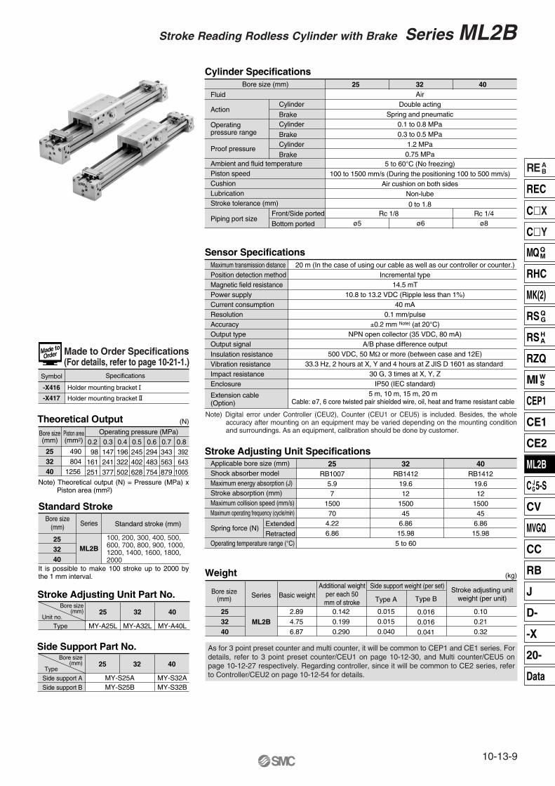
Cylinder Specifications
Sensor Specifications
Stroke Adjusting Unit Specifications
Standard Stroke
Weight
Theoretical Output
Bore size (mm)
Fluid
ActionCylinder
Brake
Operatingpressure range
Cylinder
Brake
Ambient and fluid temperaturePiston speedCushionLubricationStroke tolerance (mm)
Piping port sizeFront/Side ported
Bottom ported
AirDouble acting
Spring and pneumatic0.1 to 0.8 MPa0.3 to 0.5 MPa
1.2 MPa0.75 MPa
5 to 60°C (No freezing)100 to 1500 mm/s (During the positioning 100 to 500 mm/s)
Air cushion on both sidesNon-lube
0 to 1.8
ø5 ø6 ø8Rc 1/8 Rc 1/4
Maximum transmission distancePosition detection methodMagnetic field resistancePower supplyCurrent consumptionResolutionAccuracyOutput typeOutput signalInsulation resistanceVibration resistanceImpact resistanceEnclosure
Extension cable(Option)
20 m (In the case of using our cable as well as our controller or counter.)Incremental type
14.5 mT10.8 to 13.2 VDC (Ripple less than 1%)
40 mA0.1 mm/pulse
±0.2 mm Note) (at 20°C)NPN open collector (35 VDC, 80 mA)
A/B phase difference output500 VDC, 50 MΩ or more (between case and 12E)
33.3 Hz, 2 hours at X, Y and 4 hours at Z JIS D 1601 as standard 30 G, 3 times at X, Y, Z
IP50 (IEC standard)
Applicable bore size (mm) Shock absorber modelMaximum energy absorption (J)Stroke absorption (mm)Maximum collision speed (mm/s)Maximum operating frequency (cycle/min)
ExtendedRetracted
Spring force (N)
Operating temperature range (°C)
25RB1007
5.97
150070
4.226.86
32RB1412
19.612
150045
6.8615.98
40RB1412
19.612
150045
6.8615.98
5 to 60
253240
490 8041256
Bore size(mm)
Piston area(mm2) 0.2
98161251
0.3147241377
0.4196322502
0.5245402628
0.6294483754
0.7343563879
0.8 392 6431005
Operating pressure (MPa)
253240
Bore size(mm) Series
ML2B
Standard stroke (mm)
253240
Bore size(mm) Series
ML2B
Basic weight
2.894.756.87
Additional weightper each 50mm of stroke
0.1420.1990.290
Side support weight (per set)
Type A
0.0150.0150.040
Stroke adjusting unitweight (per unit)Type B
0.0160.0160.041
0.100.210.32
(kg)
(N)
5 m, 10 m, 15 m, 20 mCable: ø7, 6 core twisted pair shielded wire, oil, heat and frame resistant cable
25 32 40
Proof pressureCylinder
Brake
40
MY-A40LType
25
MY-A25L
32
MY-A32L
Bore size(mm)
Unit no.
Stroke Adjusting Unit Part No.
40
Side support ASide support B
25 32Bore size
(mm)Type
Side Support Part No.
MY-S25AMY-S25B
MY-S32AMY-S32B
Note) Digital error under Controller (CEU2), Counter (CEU1 or CEU5) is included. Besides, the whole accuracy after mounting on an equipment may be varied depending on the mounting condition and surroundings. As an equipment, calibration should be done by customer.
Note) Theoretical output (N) = Pressure (MPa) x Piston area (mm2)
It is possible to make 100 stroke up to 2000 by the 1 mm interval.
As for 3 point preset counter and multi counter, it will be common to CEP1 and CE1 series. For details, refer to 3 point preset counter/CEU1 on page 10-12-30, and Multi counter/CEU5 on page 10-12-27 respectively. Regarding controller, since it will be common to CE2 series, refer to Controller/CEU2 on page 10-12-54 for details.
Made to Order Specifications(For details, refer to page 10-21-1.)
-X416
-X417
Holder mounting bracket I
Symbol Specifications
Holder mounting bracket II
100, 200, 300, 400, 500, 600, 700, 800, 900, 1000, 1200, 1400, 1600, 1800, 2000
Stroke Reading Rodless Cylinder with Brake Series ML2B
10-13-9
REAB
REC
CX
CY
MQQM
RHC
MK(2)
RSQG
RSHA
RZQ
MI WS
CEP1
CE1
CE2
ML2B
C JG5-S
CV
MVGQ
CC
RB
J
D-
-X
20-
Data
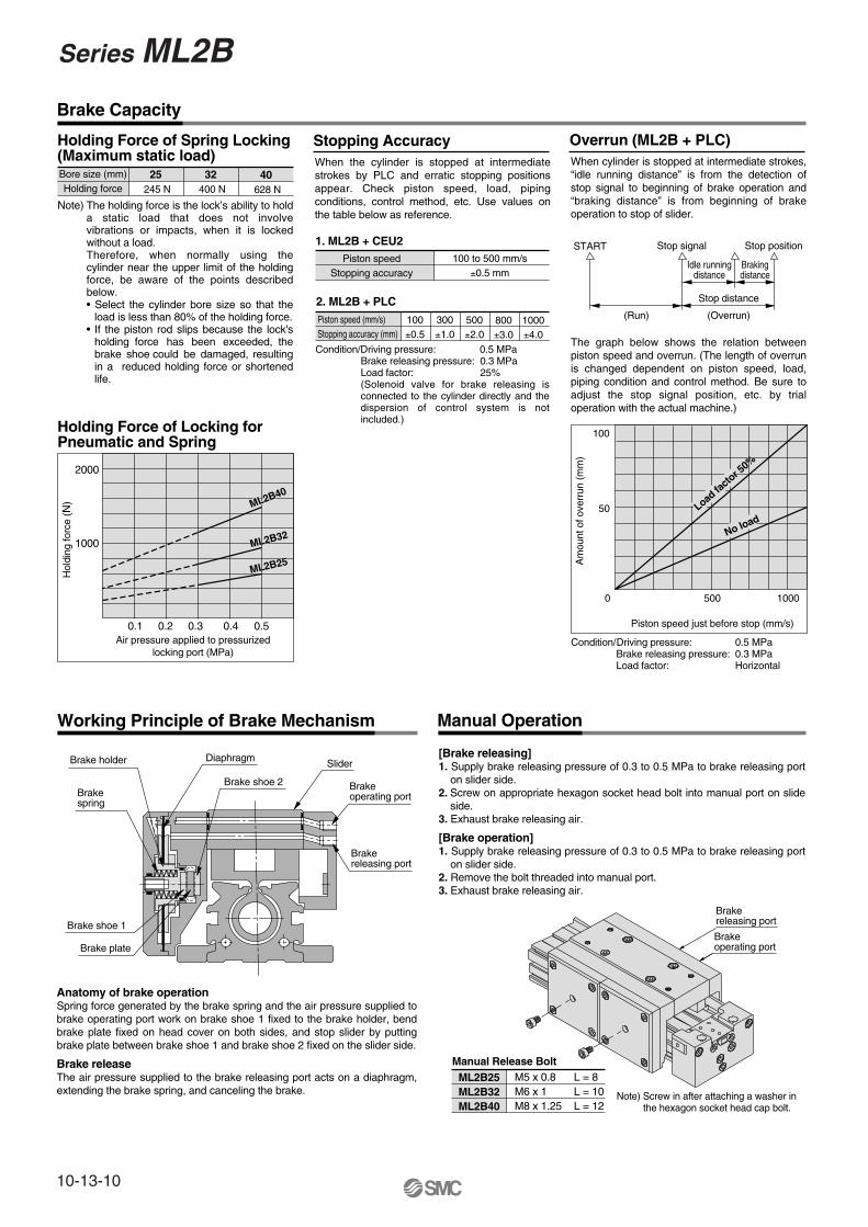
Holding Force of Locking for Pneumatic and Spring
Stopping Accuracy
1. ML2B + CEU2
2. ML2B + PLC
Piston speed (mm/s)Stopping accuracy (mm)
Piston speedStopping accuracy
100 to 500 mm/s±0.5 mm
100±0.5
300±1.0
500±2.0
800±3.0
1000±4.0
Overrun (ML2B + PLC)
Condition/Driving pressure: 0.5 MPaBrake releasing pressure: 0.3 MPaLoad factor: Horizontal
ML2B40ML2B40ML2B40
ML2B32ML2B32
ML2B25ML2B25
Air pressure applied to pressurizedlocking port (MPa)
0.1 0.4 0.50.2 0.3
Hol
ding
forc
e (N
)
1000
2000
Brake Capacity
Load fa
ctor 5
0%
No load
500 1000
50
100
Am
ount
of o
verr
un (
mm
)
Piston speed just before stop (mm/s)
0
START Stop signal Stop position
Idle runningdistance
Brakingdistance
Stop distance
(Overrun)(Run)
Bore size (mm)Holding force
25 245 N
32 400 N
40 628 N
Holding Force of Spring Locking (Maximum static load)
The holding force is the lock’s ability to hold a static load that does not involve vibrations or impacts, when it is locked without a load. Therefore, when normally using the cylinder near the upper limit of the holding force, be aware of the points described below.• Select the cylinder bore size so that the
load is less than 80% of the holding force.• If the piston rod slips because the lock's
holding force has been exceeded, the brake shoe could be damaged, resulting in a reduced holding force or shortened life.
Working Principle of Brake Mechanism
Anatomy of brake operationSpring force generated by the brake spring and the air pressure supplied to brake operating port work on brake shoe 1 fixed to the brake holder, bend brake plate fixed on head cover on both sides, and stop slider by putting brake plate between brake shoe 1 and brake shoe 2 fixed on the slider side.
Brake releaseThe air pressure supplied to the brake releasing port acts on a diaphragm, extending the brake spring, and canceling the brake.
Manual Operation
Manual Release BoltML2B25ML2B32ML2B40
M5 x 0.8 L = 8M6 x 1 L = 10M8 x 1.25 L = 12
[Brake releasing]1. Supply brake releasing pressure of 0.3 to 0.5 MPa to brake releasing port
on slider side.2. Screw on appropriate hexagon socket head bolt into manual port on slide
side.3. Exhaust brake releasing air.
[Brake operation]1. Supply brake releasing pressure of 0.3 to 0.5 MPa to brake releasing port
on slider side.2. Remove the bolt threaded into manual port.3. Exhaust brake releasing air.
Brakeoperating port
Brakereleasing port
When cylinder is stopped at intermediate strokes, “idle running distance” is from the detection of stop signal to beginning of brake operation and “braking distance” is from beginning of brake operation to stop of slider.
When the cylinder is stopped at intermediate strokes by PLC and erratic stopping positions appear. Check piston speed, load, piping conditions, control method, etc. Use values on the table below as reference.
The graph below shows the relation between piston speed and overrun. (The length of overrun is changed dependent on piston speed, load, piping condition and control method. Be sure to adjust the stop signal position, etc. by trial operation with the actual machine.)
Brake holder
Brakespring
Diaphragm
Brake shoe 2
Slider
Brakeoperating port
Brakereleasing port
Brake shoe 1
Brake plate
Note) Screw in after attaching a washer in the hexagon socket head cap bolt.
Condition/Driving pressure: 0.5 MPaBrake releasing pressure: 0.3 MPaLoad factor: 25%(Solenoid valve for brake releasing is connected to the cylinder directly and the dispersion of control system is not included.)
Note)
Series ML2B
10-13-10
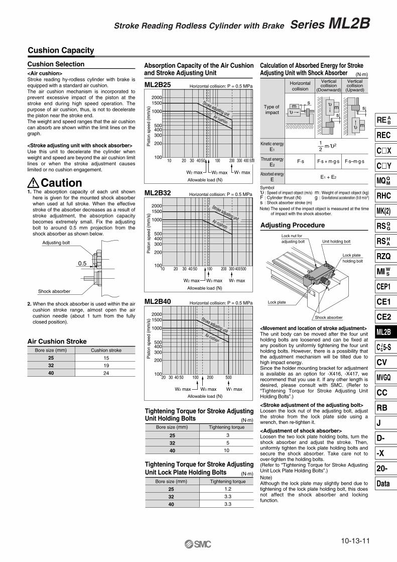
Adjusting Procedure
<Movement and location of stroke adjustment>The unit body can be moved after the four unit holding bolts are loosened and can be fixed at any position by uniformly tightening the four unit holding bolts. However, there is a possibility that the adjustment mechanism will be tilted due to high impact energy.Since the holder mounting bracket for adjustment is available as an option for -X416, -X417, we recommend that you use it. If any other length is desired, please consult with SMC. (Refer to “Tightening Torque for Stroke Adjusting Unit Holding Bolts”.)
<Stroke adjustment of the adjusting bolt>Loosen the lock nut of the adjusting bolt, adjust the stroke from the lock plate side using a wrench, then re-tighten it.
<Adjustment of shock absorber>Loosen the two lock plate holding bolts, turn the shock absorber and adjust the stroke. Then, uniformly tighten the lock plate holding bolts and secure the shock absorber. Take care not to over-tighten the holding bolts.(Refer to “Tightening Torque for Stroke Adjusting Unit Lock Plate Holding Bolts”.)Note)Although the lock plate may slightly bend due to tightening of the lock plate holding bolt, this does not affect the shock absorber and locking function.
20001500
1000
500400300
200
10020 30 40 50 100 200 500
W2 max W1 max
Allowable load (N)
Pis
ton
spee
d (m
m/s
)
ML2B40 Horizontal collision: P = 0.5 MPa
W3 max
Air cushion
20001500
1000
500400300
200
10010 20 30 40 50 100 200 300
W2 max W1 max
Allowable load (N)
Pis
ton
spee
d (m
m/s
)
ML2B32 Horizontal collision: P = 0.5 MPa
W3 max
400500
Air cushion
20001500
1000
500400300
200
10010 20 30 4050 100 200 300
W2 max W1 max
Pis
ton
spee
d (m
m/s
)
ML2B25 Horizontal collision: P = 0.5 MPa
W3 max
400
Air cushion
Stroke adjusting unit
Cushion Capacity
Cushion Selection Absorption Capacity of the Air Cushion and Stroke Adjusting Unit<Air cushion>
Stroke reading hy-rodless cylinder with brake is equipped with a standard air cushion.The air cushion mechanism is incorporated to prevent excessive impact of the piston at the stroke end during high speed operation. The purpose of air cushion, thus, is not to decelerate the piston near the stroke end. The weight and speed ranges that the air cushion can absorb are shown within the limit lines on the graph.
<Stroke adjusting unit with shock absorber>Use this unit to decelerate the cylinder when weight and speed are beyond the air cushion limit lines or when the stroke adjustment causes limited or no cushion engagement.
1. The absorption capacity of each unit shown here is given for the mounted shock absorber when used at full stroke. When the effective stroke of the absorber decreases as a result of stroke adjustment, the absorption capacity becomes extremely small. Fix the adjusting bolt to around 0.5 mm projection from the shock absorber as shown below.
2. When the shock absorber is used within the air cushion stroke range, almost open the air cushion needle (about 1 turn from the fully closed position).
Adjusting bolt
Shock absorber
0.5
Air Cushion StrokeBore size (mm)
25
32
40
Cushion stroke
15
19
24
500
Allowable load (N)
Tightening Torque for Stroke Adjusting Unit Holding Bolts (N·m)
(N·m)
Bore size (mm) Tightening torque
Tightening Torque for Stroke Adjusting Unit Lock Plate Holding Bolts
Bore size (mm) Tightening torque
1.2
3.3
3.3
Calculation of Absorbed Energy for Stroke Adjusting Unit with Shock Absorber
Horizontalcollision
Verticalcollision
(Downward)
Verticalcollision
(Upward)
Type of impact
Kinetic energyE1
Thrust energyE2
Absorbed energyE
1— m·υ2 2
F·s F·s + m·g·s F·s–m·g·s
E1 + E2
Symbolυ : Speed of impact object (m/s)F : Cylinder thrust (N)s : Shock absorber stroke (m)
m: Weight of impact object (kg)g : Gravitational acceleration (9.8 m/s2)
s
υ m
Lock nut foradjusting bolt Unit holding bolt
Lock plate
holding bolt
Lock plate
Shock absorber
Stroke adjusting unit
Stroke adjusting unit
25
32
40
25
32
40
υm
ss
υ m
Caution
Note) The speed of the impact object is measured at the time of impact with the shock absorber.
(N·m)
3
5
10
Stroke Reading Rodless Cylinder with Brake Series ML2B
10-13-11
REAB
REC
CX
CY
MQQM
RHC
MK(2)
RSQG
RSHA
RZQ
MI WS
CEP1
CE1
CE2
ML2B
C JG5-S
CV
MVGQ
CC
RB
J
D-
-X
20-
Data

@7
!6
e
q
@0 i !9 !8 !7 !1 r #6 @3 #9 @7 y u t !5 #8 #9
w
#5#4$9$1$0 1 0
$6
$5
$4
$3
$2
%4
!4
$7 $8 0 !2 #2 @4 !3 %0 %1 %2
%3
2
%5
%6
%7
%8
%9ML2BS
!0@23 @1 #3
#1
@6
@5
0
@8
o
#0
5
7
6
4
Construction
Series ML2B
10-13-12

Seal ListNo.!4
!5
!7
!8
!9
@0
@8
#4
$2
$3
$9
%2
0
7
Description MaterialSpecial resinStainless steelNBRNBRNBRNBRNBRNBRNBRNBRNBRNBRNBRNBR
Seal beltDust seal band
ScraperPiston seal
Cushion sealTube gasket
O-ringO-ringO-ringO-ringO-ring
Connector guide O-ringO-ring
Qty.11222224221162
ML2B25 ML2B32 ML2B40MY25-16A-strokeMY25-16B-strokeMYB25-15AA5900
GMY25RCS-8
NLP-25-19Aø7.15 x ø3.75 x ø1.7
P-5SO-015-16
P-7SO-010-16
M2L025-07B82106SO-010-20
ø17.6 x ø19.4 x ø0.9
MY32-16A-strokeMY32-16B-strokeMYB32-15AA5901
GMY32RCS-10NLP-32A
ø8.3 x ø4.5 x ø1.9P-6
SO-016-9P-9
SO-010-21M2L032-07B82107
SO-010-21ø22.2 x ø24 x ø0.9
MY40-16A-strokeMY40-16B-strokeMYB40-15AA5902
GMY40RCS-12NLP-40A
C-4C-9
SO-015-20P-11
SO-010-24M2L040-07B82108
SO-010-24ø28 x ø30 x ø1
No.q
w
e
r
t
y
u
i
o
!0
!1
!2
!3
!6
@1
@2
@3
@4
@5
@6
@7
@9
#0
#1
#2
#3
#5
#6
#7
#8
#9
$0
$1
$4
$5
$6
$7
$8
%0
%1
%3
%4
%5
%6
%7
%8
%9
1
2
3
4
5
6
8
DescriptionCylinder tubeHead cover WRHead cover WLPiston yokePistonEnd coverWear ringCushion ringCushion needleStopperBelt separatorGuide rollerGuide roller shaftBelt clampBearingSpacerSpring pinType E snap ringHexagon socket head cap screwHexagon socket button head screwHexagon socket head set screwDouble round parallel keyHexagon socket head taper plugMagnetTop coverSide scraperHexagon socket head taper plugRound head Phillips screwHexagon socket head cap screwParallel pinTension plateSide cover LSide cover RBrake shoeBrake plate Diaphragm shellDiaphragmBrake guideSlide tableSensor bodyRound head Phillips screwBrake guideConnector coverSensor guideScale plateHexagon socket head cap screwSensor unitAir jointSensor holder Hexagon socket head cap screwCross recessed countersunk head screwBrake springSide plateHexagon socket head cap screw
MaterialAluminum alloyAluminum alloyAluminum alloyAluminum alloyAluminum alloySpecial resinSpecial resin
Stainless steelRolled steelCarbon steelSpecial resinSpecial resin
Stainless steelSpecial resinSpecial resin
Stainless steelCarbon tool steel
Cold rolled special steel stripChromium molybdenum steelChromium molybdenum steelChromium molybdenum steel
Carbon steelCarbon steel
Rare earth magnetStainless steelSpecial resinCarbon steelCarbon steelCarbon steelCarbon steelCarbon steel
Aluminum alloyAluminum alloy
Special abrasion material Stainless steelStainless steel
NBRAluminum alloyAluminum alloyAluminum alloyCarbon steelCarbon steelCarbon steel
Special abrasion material Carbon steelCarbon steel
—Stainless steelCarbon steelCarbon steelCarbon steel
—Aluminum alloy
Chromium molybdenum steel
Component PartsNote
Hard anodizedGlossy, self-coloringGlossy, self-coloring
Hard anodizedHard anodized
Nickel plated
Black zinc chromated
Nickel platedNickel platedNickel plated
Nickel plated
Nickel platedNickel platedNickel plated
Nickel platedHard anodized, Urban whiteHard anodized, Urban white
Hard anodized, whiteHard anodized
Hard anodized, whiteNickel plated
Gas soft treatedNickel plated
Nickel platedNickel plated
Hard anodized, whiteNickel plated
Qty.111122222421122422648262124434411414211122111211184216
AB
A: Black zinc chromate color: MY-16B-StrokeB: Nickel color: MY-16BW-Stroke
∗ Since there is a possibility of improper operation, please contact SMC regarding the replacement of seals.
∗ There are two dust seal bands, and part no. is different according to color of the treated “Hexagon socket head set screw” of @7. Please contact SMC.
Stroke Reading Rodless Cylinder with Brake Series ML2B
10-13-13
REAB
REC
CX
CY
MQQM
RHC
MK(2)
RSQG
RSHA
RZQ
MI WS
CEP1
CE1
CE2
ML2B
C JG5-S
CV
MVGQ
CC
RB
J
D-
-X
20-
Data
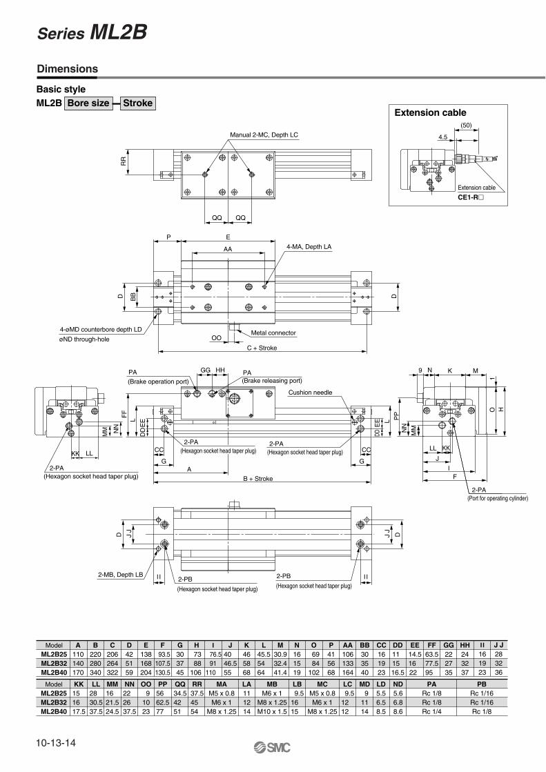
ModelML2B25ML2B32ML2B40
J J283236
LC 9.512 12
LD5.56.58.5
PARc 1/8Rc 1/8Rc 1/4
KK15 16 17.5
LL28 30.537.5
OO 91023
PP56 62.577
QQ34.542 51
RR37.545 54
LA111214
ModelML2B25ML2B32ML2B40
A110140170
K465868
L45.554 64
M30.932.441.4
N161519
O 69 84102
P415668
CC161923
BB303540
AA106133164
B220280340
C206264322
D425159
E138168204
F 93.5107.5130.5
G303745
H 73 88106
I 76.5
91110
J40 46.555
DD11 15 16.5
EE14.516 22
FF63.577.595
GG222735
HH243237
MBM6 x 1
M8 x 1.25M10 x 1.5
I I161923
MAM5 x 0.8M6 x 1
M8 x 1.25
2-PA 2-PA
2-PA(Hexagon socket head taper plug)
(Hexagon socket head taper plug) (Hexagon socket head taper plug)
Cushion needle
(Hexagon socket head taper plug) (Hexagon socket head taper plug)
2-PB2-PB2-MB, Depth LB
Manual 2-MC, Depth LC
QQ QQ
RR
E
AA
P
D
4-øMD counterbore depth LD
øND through-holeC + Stroke
Metal connector
D
4-MA, Depth LA
OO
MM
KK LL
NN
B + Stroke
FF
HH
L
DD
EE
AG
CC
G
L
DDE
EGG PA
(Brake releasing port)PA
(Brake operation port)
D J J
DJ J
O H
FI
J
LL KK
2-PA(Port for operating cylinder)
9 N K M
PP
NN
MM
I I
MM16 21.524.5
NN22 26 37.5
LB 9.516 15
MCM5 x 0.8M6 x 1
M8 x 1.25
MD 91114
ND5.66.88.6
PBRc 1/16Rc 1/16Rc 1/8
BB
CC
1
I I
Extension cable
CE1-R
Extension cable(50)
4.5
Basic styleML2B Bore size Stroke
Dimensions
Series ML2B
10-13-14
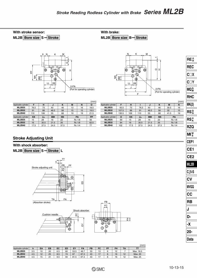
Applicable cylinder ML2B25ML2B32ML2B40
h3.54.54.5
Stroke Adjusting Unit
EA101215
EB202531
EC6.58.59.5
EY53.567 81.5
FA46.767.367.3
FB334343
FC131717
FF666
FH121616
TA 71212
TTMax. 16.5Max. 20Max. 25
Applicable cylinder ML2B25ML2B32ML2B40
Applicable cylinder ML2B25ML2B32ML2B40
KK15 16 17.5
LL28 30.537.5
MM16 21.524.5
PARc 1/8Rc 1/8Rc 1/4
NN22 26 37.5
PP56 62.577
O6984
102
KK15 16 17.5
LL28 30.537.5
PARc 1/8Rc 1/8Rc 1/4
MM16 21.524.5
Applicable cylinder ML2B25ML2B32ML2B40
Applicable cylinder ML2B25ML2B32ML2B40
F76.591
110
H7388
106
J40 46.555
K465868
M131519
N161519
O18.519.521.5
F 93.5107.5130.5
H7388
106
N161519
I 76.5
91110
J40 46.555
K465868
M30.532 41.5
2-PA(Port for operating cylinder)
9 N K M
O1
H
F
MM
J
KKLL
NN
PP
ED
TT
TA FA(Absorber stroke)
h
EB FF
EAStroke adjusting unit
Cushion needle
Shock absorber
EY
EC
FH
FC
FB
NN22 26 37.5
ED607494
2-PA(Port for operating cylinder)
N K M
O H
I
MM
J
KKLL
NN
F
1
(mm)(mm)
(mm)
With stroke sensor:
ML2B Bore size S Stroke
With shock absorber:
ML2B Bore size S Stroke L
With brake:
ML2B Bore size B Stroke
Stroke Reading Rodless Cylinder with Brake Series ML2B
10-13-15
REAB
REC
CX
CY
MQQM
RHC
MK(2)
RSQG
RSHA
RZQ
MI WS
CEP1
CE1
CE2
ML2B
C JG5-S
CV
MVGQ
CC
RB
J
D-
-X
20-
Data
W
W
Wl
l
l l
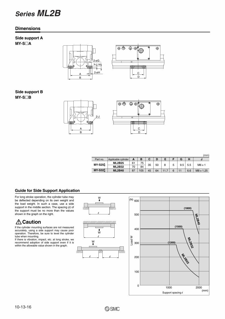
Guide for Side Support Application
Part no.
MY-S25A
MY-S32A
B
B
Applicable cylinderML2B25ML2B32ML2B40
A617087
B 75 84105
C
35
45
D
50
64
E
8
11.7
F
5
6
G
9.5
11
H
5.5
6.6
J
M6 x 1
M8 x 1.25
For long stroke operation, the cylinder tube may be deflected depending on its own weight and the load weight. In such a case, use a side support in the middle section. The spacing (l) of the support must be no more than the values shown in the graph on the right.
If the cylinder mounting surfaces are not measured accurately, using a side support may cause poor operation. Therefore, be sure to level the cylinder tube when mounting.If there is vibration, impact, etc. at long stroke, we recommend adoption of side support even if it is within the allowable value shown in the graph.
Side support AMY-SA
Side support BMY-SB
0
Load
W
600
500
400
300
200
Support spacing l
1000 2000(mm)
100
(N)
2-J
AB
2-øG
2-øH
F E
CD
CD
AB
(1800)
(1500)
(1200)(1200)
Caution
Dimensions
(mm)
ML2B
40M
L2B40
ML2B
32
ML2B
25
Series ML2B
10-13-16
Caution on Handling Auto Switch Mounting of Auto Switch
M2.5 x 4l
(Included with the auto switch)
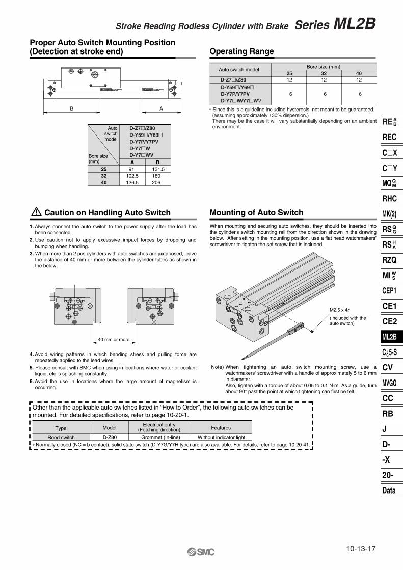
Proper Auto Switch Mounting Position (Detection at stroke end) Operating Range
253240
91 102.5126.5
131.5180 206
AB
Auto switch model
D-Z7/Z80D-Y59/Y69D-Y7P/Y7PVD-Y7WD-Y7WVBore size
(mm)
Autoswitchmodel
A B
Bore size (mm)2512
6
3212
6
4012
6D-Y59/Y69D-Y7P/Y7PVD-Y7W/Y7WV
D-Z7/Z80
Type Model Features
Without indicator light
Electrical entry(Fetching direction)
D-Z80 Grommet (In-line)
Other than the applicable auto switches listed in “How to Order”, the following auto switches can be mounted. For detailed specifications, refer to page 10-20-1.
∗ Normally closed (NC = b contact), solid state switch (D-Y7G/Y7H type) are also available. For details, refer to page 10-20-41.Reed switch
40 mm or more
∗ Since this is a guideline including hysteresis, not meant to be guaranteed. (assuming approximately ±30% dispersion.)There may be the case it will vary substantially depending on an ambient environment.
1. Always connect the auto switch to the power supply after the load has been connected.
2. Use caution not to apply excessive impact forces by dropping and bumping when handling.
3. When more than 2 pcs cylinders with auto switches are juxtaposed, leave the distance of 40 mm or more between the cylinder tubes as shown in the below.
4. Avoid wiring patterns in which bending stress and pulling force are repeatedly applied to the lead wires.
5. Please consult with SMC when using in locations where water or coolant liquid, etc is splashing constantly.
6. Avoid the use in locations where the large amount of magnetism is occurring.
When mounting and securing auto switches, they should be inserted into the cylinder's switch mounting rail from the direction shown in the drawing below. After setting in the mounting position, use a flat head watchmakers’ screwdriver to tighten the set screw that is included.
Note) When tightening an auto switch mounting screw, use a watchmakers' screwdriver with a handle of approximately 5 to 6 mm in diameter.Also, tighten with a torque of about 0.05 to 0.1 N·m. As a guide, turn about 90° past the point at which tightening can first be felt.
Stroke Reading Rodless Cylinder with Brake Series ML2B
10-13-17
REAB
REC
CX
CY
MQQM
RHC
MK(2)
RSQG
RSHA
RZQ
MI WS
CEP1
CE1
CE2
ML2B
C JG5-S
CV
MVGQ
CC
RB
J
D-
-X
20-
Data