STRESS INTENSITY FACTOR VARIATION ALONG A … · “infinite” in extent (or roughly 5 times...
20
Engineering Fmcture Mechanics Vol. 34, No. 4, pp. 951-916, 1989 0013-79+4/89 $3.00 + 0.00 Printed in Great Britain. 0 1989 Pergamon Press plc. STRESS INTENSITY FACTOR VARIATION ALONG A SEMICIRCULAR SURFACE FLAW IN A FINITE-THICKNESS PLATE C. Y. LIAO and S. N. ATLURI Center for Computational Mechanics, Georgia Institute of Technology, Atlanta, GA 30332-0356, U.S.A. Abstract--The stress intensity factor variation along a semicircular surface law in a three dimensional solid @late) of finite thickness is derived. This is done using a nested alternating procedure which employs the complete analytical solution for an arbitrarily loaded circular flaw embedded in an infinite solid. The method accounts for both the front-surface/backsurface as well as the boundary-crack interactions, as opposed to the method of Thresher and Smith (J. appl. Me& 39, 195-200, 1972) which considered only the boundary-crack interactions. In the present method, the residual tractions on the front and back surfaces, during the alternating procedure, are erased using Love’s half-space solutions. Various numerical examples of tension and flexure loads are given. Results obtained by this method are compared with available experimental and computational data. 1. INTRODUCTION T?imaz-dimensional Fracture Mechanics has drawn much attention in recent years as computer technology evolves into new and more powerful forms. In the context of LEFM (Linear Elastic Fracture Mechanics) the central problem is to determine the stress intensity factors which characterize the singular stress field in the neighborhood of the crack tip. Based on the known values of the stress intensity factors, the fatigue life and fracture strength of the structure can be predicted through empirical formulae. For 3D failure assessment, the prexisting flaws in the engineering structure are often idealized to be circular or elliptical for algebraic convenience. Of the various crack geometries that occur in normal service .conditions, the surface flaw was found to be one of the most prevalent[ 11. The numerical analysis of a surface flaw requires the proper handling of a high stress gradient near the free boundary surface as well as the singular stress field along the crack front. Among the popular numerical techniques for solving this problem are the singular finite element and the Scharwz-Neumann alternating method. Although both these methods yield similar levels of accuracy when properly implemented, the latter exhibits enormous computational advantages over the former[2]. These advantages are very significant when the stress intensity factors are needed for various design loads and crack dimensions. Early use of the alternating method for 3D circular flaws dates back to Smith et a1.[3,4] in which the circular and semicircular crack problems were solved for infinite and semi-infinite solids. Later, Smith and Alavi[S], and Thresher and Smith[6] extended the method to a finite-thickness solid, and Hartranft and Sih[7] discussed the boundary layer effect due to the loss of plane strain conditions at the intersections of the front surface and the crack. For practical purposes, circular crack problems have also been solved as elliptical cracks with near circular shape, but these results were extremely unstable as the ratio of the minor and major axes approached unity. Consequently, limiting ratios of 0.982 and 0.95, for embedded and surface elliptical flaws, respectively, were used by Shah and Kobayashi[8], and Kobayashi et aZ.[9]. For .an embedded crack, the stress intensity factor solution based on these limiting values was within a + 1.2 to - 2.9% precision of the exactly circular crack solution[8]. For surface flaw problem, however, the stress intensity factors deviated sharply from the circular solution for polar angles between 0 and 30”[9]. No success in solving the semicircular surface flaw problem by an elliptical approximation has been reported so far. In the above investigations [l, 4-91 the alternating method was implemented using two analytical solutions (hereinafter referred to as the analytical alternating method), i.e. solution of half-space elasticity problem and that for a crack in an infinite solid, so that highly accurate 957
Transcript of STRESS INTENSITY FACTOR VARIATION ALONG A … · “infinite” in extent (or roughly 5 times...

Engineering Fmcture Mechanics Vol. 34, No. 4, pp. 951-916, 1989 0013-79+4/89 $3.00 + 0.00 Printed in Great Britain. 0 1989 Pergamon Press plc.
STRESS INTENSITY FACTOR VARIATION ALONG A SEMICIRCULAR SURFACE FLAW IN
A FINITE-THICKNESS PLATE
C. Y. LIAO and S. N. ATLURI
Center for Computational Mechanics, Georgia Institute of Technology, Atlanta, GA 30332-0356, U.S.A.
Abstract--The stress intensity factor variation along a semicircular surface law in a three dimensional solid @late) of finite thickness is derived. This is done using a nested alternating procedure which employs the complete analytical solution for an arbitrarily loaded circular flaw embedded in an infinite solid. The method accounts for both the front-surface/backsurface as well as the boundary-crack interactions, as opposed to the method of Thresher and Smith (J. appl. Me& 39, 195-200, 1972) which considered only the boundary-crack interactions. In the present method, the residual tractions on the front and back surfaces, during the alternating procedure, are erased using Love’s half-space solutions. Various numerical examples of tension and flexure loads are given. Results obtained by this method are compared with available experimental and computational data.
1. INTRODUCTION
T?imaz-dimensional Fracture Mechanics has drawn much attention in recent years as computer technology evolves into new and more powerful forms. In the context of LEFM (Linear Elastic Fracture Mechanics) the central problem is to determine the stress intensity factors which characterize the singular stress field in the neighborhood of the crack tip. Based on the known values of the stress intensity factors, the fatigue life and fracture strength of the structure can be predicted through empirical formulae.
For 3D failure assessment, the prexisting flaws in the engineering structure are often idealized to be circular or elliptical for algebraic convenience. Of the various crack geometries that occur in normal service .conditions, the surface flaw was found to be one of the most prevalent[ 11. The numerical analysis of a surface flaw requires the proper handling of a high stress gradient near the free boundary surface as well as the singular stress field along the crack front. Among the popular numerical techniques for solving this problem are the singular finite element and the Scharwz-Neumann alternating method. Although both these methods yield similar levels of accuracy when properly implemented, the latter exhibits enormous computational advantages over the former[2]. These advantages are very significant when the stress intensity factors are needed for various design loads and crack dimensions.
Early use of the alternating method for 3D circular flaws dates back to Smith et a1.[3,4] in which the circular and semicircular crack problems were solved for infinite and semi-infinite solids. Later, Smith and Alavi[S], and Thresher and Smith[6] extended the method to a finite-thickness solid, and Hartranft and Sih[7] discussed the boundary layer effect due to the loss of plane strain conditions at the intersections of the front surface and the crack. For practical purposes, circular crack problems have also been solved as elliptical cracks with near circular shape, but these results were extremely unstable as the ratio of the minor and major axes approached unity. Consequently, limiting ratios of 0.982 and 0.95, for embedded and surface elliptical flaws, respectively, were used by Shah and Kobayashi[8], and Kobayashi et aZ.[9]. For .an embedded crack, the stress intensity factor solution based on these limiting values was within a + 1.2 to - 2.9% precision of the exactly circular crack solution[8]. For surface flaw problem, however, the stress intensity factors deviated sharply from the circular solution for polar angles between 0 and 30”[9]. No success in solving the semicircular surface flaw problem by an elliptical approximation has been reported so far.
In the above investigations [l, 4-91 the alternating method was implemented using two analytical solutions (hereinafter referred to as the analytical alternating method), i.e. solution of half-space elasticity problem and that for a crack in an infinite solid, so that highly accurate
957

958 C. Y. LIAO and S. N. ATLURI
numerical results could be obtained. However, recently in a critical evaluation of numericaf solutions to the benchmark surface flaw problem[lO], it was dete~in~ that the analytical alternating method for ~~-t~ckn~s solid, ~derest~ated the stress intensity factors by a margin of lO-25% all along the crack front. Although several reasons have been given[lO], the main cause for this fault was still not known.
In this work we revise the analytical alternating method for a finite-thickness solid[(i] by employing an additional alternating loop to account for the interactions between the front and back surfaces, as well as interactions between these surfaces and the crack face. We then correlate the alternating procedure with Neumann's[l 1] idea of orthogonal projections in Hilbert space to gain a better understanding of the method. The analytical solution, of a circular crack embedded in an infinite elastic body is summarized for completeness, and to point out the ambiguity in the work of Kassir and Sih[l2]. We also present the complete solution of the problem of Boussinesq and Cerruti with constant shear tractions at locations on the half-space. This has been partially derived by Smith and Alavi[5], and Shah and Kobayashi[lg], and is used in the additional alternating loop. The current numerical results show a significant improvement from the previous investigations when compared with the results of Newman and Raju[l3] and the experimental data of Smith and Kirby[lrlj, and Ruiz and Epstein[lS].
2. PROBLEM STATEMENT
As shown in Fig. 1, the subject problem consists of a semicircular crack, a front boundary surface, and a back boundary surface. Both the front and back surfaces are considered to be “infinite” in extent (or roughly 5 times larger than the crack dimensions). In the context of linear elasticity, the stress intensity factor variation is to be solved as a function of the polar angle 8 along the crack front. The effects of various ratios of crack depth to plate thickness will also be examined.
3. PENNY-SHAPED CRACK IN AN INEINITE SOLID
The elasticity solution of an embedded circular crack in an infinite solid is used to analytically represent the singular natures of stresses near the crack front, in the alternating process. This solid is described by three cylindrical coordinates r, 8 and z, such that the crack face coincides with the plane z = 0. The problem was first solved by Sneddon[ 161 using an integral transform method, and the same technique was extended by Kassir and Sih[l2] to derive the general solution of a circular crack subjected to arbitrary tractions. The complete form of the general solution is summarized as follows.
Fig. 1. Semicircular flaw in an infinite plate of finite-thickness.

SIF variation along a surface flaw 959
For a penny-shaped crack embedded in an infinite 3D elastic body, we need to solve the following mixed boundary value problems
MO& I
dr, 40) = 0dr, e, 0) = 0, r 2 0, oged27c
b,,tr, 8, 0) = p1 tr, 01, Ogrra, OGt3822n
u,tr, 8, 0) = 0, r > a, 0<@82n
(a is the crack radius)
Modes II and III
(la)
o&, 8, 0) = 0, r 30, OG6G22n
0, (r, 40) = pz (r, 0 OGrra, oGee22n
dry e, 0) =P&, e), OsSr-ca, OG0827t
u,(r, 8, 0) = u@(r, e,O) = 0, r >a, O&:eg2n (lb)
where p,(r, 0) (a = 1,2,3) are given functions describing the distribution of the loads applied to the crack face.
An appropriate solution for the above Sunday-v~ue problem can be obtained by expressing the displacement ~m~nents in terms of three harmonic functions &(cr = 1,2,3), as
84, r&=(1 -2v)7$ fz a*4 2acp2 drar+;dB+2(1-v)!$+z~
iad4 z a*44 q?=(l-2+&j- +;s -
2 84, 2 a% ar+2(1 -v+$J+-- r aeaz
ah a% u*= -2(1 -v)T&+t az2 ---(1-2v)~+E~.
The corresponding stress components are given in the following
d **=a.4 [
w, av, 3 -w+z3 1 +2Ly 3
3
C&=2/4 (*-2v)!$:2v!$+z$$, [
2 2 + 2P [ 84, a*+* -7’+- rz&j+2(1-v)~-2v~+r~
ar*az 1 Qe = 34 [
i a4l ;7+2v-
a*+, + i aq, ~a*$, 2 a34,
&* ;Ia82+;z!G+;Ia82az 1 +2cI [ 2 w2 2avh w3 ---;~-w-v) art
r2 ae __2v~_z~(~+~)]
6, = 2fiz ;r;zi 7+2cl [
$$+$$+z$$]
,? J34, Cr&=2fi;-z&+2/l -- -- [
a*#* + 1 a249 z av3
araz rd0dz+ra0a~2 1 --
bti=-F- 2p (la&) y!b+ci!& [ ( > ~a*+, -;ZZ+z&]
(2)
+2p ;gL-@+--_-- [
a*+* 1 a2#* 2(1- ~)a#, 2(1 -v) a243 z a24 r a343
r* de* r2 $30 +~---- --
ara8 r* aea2 + r ara& 1 * (3)

960 C Y. LIAO and S. N. ATIJJRI
The above stresses are the physical ~rn~nen~ in the cylindrical coordinates. It will be seen that 4l is related to mode I, and rpZ and fpj are related to modes II and III. In order to de& arbitrary loadings, the applied crack face tractions P,(r, 0) are represented by a Fourier series as follows:
(4)
in which the Fourier coefficients are determined from
A@&)=i s
’ P,(r, 6) d0 n 0
P~(~,~~sn@d~, n=l,2 ,...
A$&-) = 0
A:(r)=? s x
x 0 P,(r,B)sinn@dB, n=l,2 ,...
The technique of Fourier-Hankel transform[l6] is used to represent the potential functions. This gives
where J, is the Bessel function of the first kind of order n and the functions C&s) and C&(s) are as yet unknown. Substitution of eqs (2)-(5) into the boundary conditions, i.e. (la) and (lb), yields the final results:
s
‘t’+‘A,,(r)dr n > 0 o (t2 - $)I/2 ’ ’
s * t”+‘A :,(r)dr ?Z>O o (9 - r2)W ’ (6)
(7)
SIF variation along a surface flaw 961
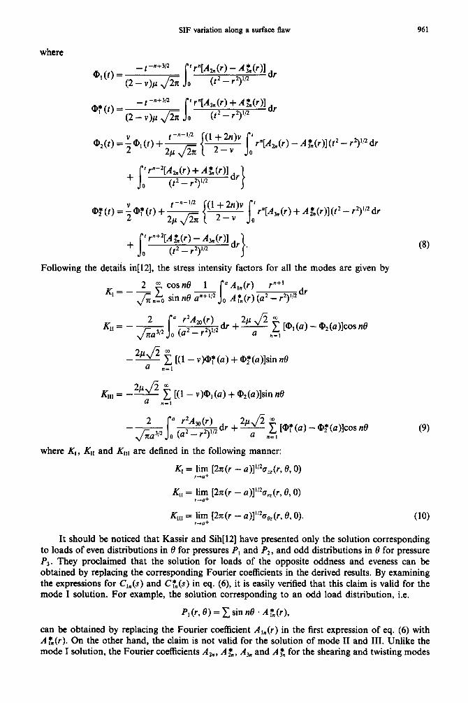
where
@IO) = _ t -n+w s f +L(r) - Af(r)l&
(2-v)&/% 0 (t2 - r3"'
Q?(t)= _ t -n+w
(2 - v)p JZ f
W,n(~)+JG(~)ldr
o (t2 - r2V2
a34@,(t)+ s {(l:_f;)' j;r"[R,(r) -A:,(r)](t2 - r2)1/2 dr
+ s ’ rn+2[A t(r) - &(r)l dr
0 (t2 - r2)‘/2 *
Following the details in[12], the stress intensity factors for all the modes are given by
dr
s
* r2Am(r) o (u2 _ r2),,2dr +
24 m u “z, [%(4 - @2(41cosne
- anzl [(l - v)@:(a) + @,,*(a)lsin no
34 O” K,,, = -- a “5 [u - w, (4 + @2Wlsin no
(8)
(9)
where K,, K,, and K,,, are defined in the following manner:
K, = lim [27r(r - ~)]“~o,(r, 0,O) I-a+
K,, = lim [2z(r - u)]“‘a,,(r, 8,O) r-f?+
KM = lim [2n(r - u)]‘/2a,(r, 8, 0). 1+(1+ (10)
It should be noticed that Kassir and Sih[l2] have presented only the solution corresponding to loads of even distributions in 0 for pressures P, and P2, and odd distributions in 8 for pressure P3. They proclaimed that the solution for loads of the opposite oddness and eveness can be obtained by replacing the corresponding Fourier coefficients in the derived results. By examining the expressions for C,,,(S) and CT,(s) in eq. (6), it is easily verified that this claim is valid for the mode I solution. For example, the solution corresponding to an odd load distribution, i.e.
P, (r, e) = 1 sin n0 - A T”(r),
can be obtained by replacing the Fourier coefficient A,,,(r) in the first expression of eq. (6) with A:,(r). On the other hand, the claim is not valid for the solution of mode II and III. Unlike the mode I solution, the Fourier coefficients Ah, A$,, AL and A$ for the shearing and twisting modes

962 C. Y. LIAO and S. N. ATLURI
are coupled together in eqs (7) and (8) irregularly. As a result, the solution corresponding to loads of an odd distribution for P2 and an even distribution for P3 cannot be obtained from the solution derived in Kassir and Sih[l2] by replacing the coefficients. A complete derivation of the circular crack solution can be found in ref. [17’J.
4. AN ELASTIC HALF&PACE SUBJECTED TO SURFACE TRACTIONS
The analytical alternating method requires the solution for stresses in the half-space when the boundary plane is subjected to arbitrary tractions. The plane is first divided into many small m%angular c&s such that the tractions in each ceh approach constant values. The stresses in the half-space are then obtained by accumulating contributions from every cell. The complete solution for the case when the boundary plane is subjected to a constant normal traction in a rectangular patch on the plane was derived by Love[l8]. Later, the solution for a,, in the half-space, due to a constant shear traction in a rectangular patch on the boundary plane was derived by Smith and Alavi[sj, and Shah and Kobayashi[l9]. As needed for the a~~yt~~aZ alternating method, the complete solution for the stress field corresponding to the case of constant shear tractions is derived here. A detailed procedure of the derivation can be found in Love[l8] and is omitted.
Figure 2 shows the coordinate system used for the half-space solution. The boundary conditions are
a,,(~, y, 0) = a,,(~, y, 0) = a,,(~, y, 0) = 0 otherwise. (11)
The fo~u~tion used is that presented by Love[20] in which the displa~ments are given by:
for X,#O
1
[
a~, za\y [email protected] vay-lay 1
i (1-2~)~ 2aY w=G --T--- [ --- 2 a2 1 (12)
Fig. 2. Coordinate system for half space solution.

SIF variation along a surface flaw 963
where
F = X, log@ + R)dx’ dy ’
YaF Y 3-,
ax
R = [(x - x’)* -t (y - y’)* + 2J1’*
for Y,#O
1
[
av, 289 u=T&i vdx-?ax 1
1 ZG zayr o=Zji
1
[ -+va; a2 ---- 2 ay 1 i (1-2~)~ ?av
w=& 2 [ -a-
2 a2 1 where
log (2 + R&ix’ dy
YaG Y =--, ay 1= \Ydz
s
(13)
(14)
(15)
(R is the same as defined in eq. 13). The corresponding stress components are obtained by differentiating the displacements and
applying the stress-strain law, which yields
for X,#O
i a2F a
a*\fli a9 xy= 2n [
-+2v--z---- ayaz axay axay 1 -1 a*y
by"=2nz$z
where the derivatives of the potential functions are obtained by the procedure outlined in Loveil g] as follows:
ay _=Xlog fb*+UJ -Y)l‘k&-(~+Yll az v [ h-fb +r)l*k+@ -YI 1

964 C. Y. LIAO and S. N. ATLURI
@ -xl (a+x) (a +x1 (a -xl u,(z+u,)-b,(z+b,)+cg(z+cj)+dd(z+d,)
(b +y) (b -v) (b +Y) u,(z+u,)-d,(z+d,)+b,(z+b,)+q(z+q)
a2F - -Xv !A - tan-’ 4
dzZ-- (u-x;b-y)-tan-‘(u-x)(b+y)
& --an-‘(u+x)(b-y)-tan-‘(u+x;;b+y)
a= 27~
I
Ixku,iyI<b 0 otherwise
a2F - =*vlog
a - x)lh - (a + xl1 ayaz ;:;u -X)][Cg--(a +x)]
a9, a9 z Ix b-y+b+y b-y b+y ay2= ay2 v u, T--&--m c3 (-
a2y a2y -=z-+x, u+x u+x u-x
axay axay +b,-f,- UI = [(a - x)~ + (b - Y)~ + z2]“’
b2 = [(a + x)~ + (b - y)2 + ~~1”~
c3 = [(a + x)~ + (b + y)2 + z~]“~
d4 = [(a - x)~ + (b + y)2 + z)“~
for Y, # 0
d _=& [
a2y a3 2vg+2v ax --T-yp 1
qy=& [
ay 2(1 +v)~+2uf3-z~ ay2 ay2 1
(17)

SF variation along a surface flaw
-1 a+ d “=211=axaz
where
ayI M + (a - x)1 s 1b2 - (a + xl] Z- [q-i-(a-x)].[c3-(a+x)] 1
@ +y) tb -u) tb +v) bd= +bz)+cdz +c,)-a,(= +a,)-d,(z +d,)
(42+x) (a-x) (a-x) (a+x)
C~(Z + cs) + de(z + 4) - a,(= + a,) -b&z + b2f
a*G -Y, O-tan-’
I “’ g= (a -XI@ -Y)
- tan-’ =d, (a -XI@ +Y)
=bz - tan-‘(a+x)(b-y)-tan-‘(a+x;b+y)
BI 2~
1
/xi<a,jyj<b 0 otherwise
a2G y log Pz+@ -yllM-@+y)l axi7z= y k3-@+yllh+(b -_y)l
$9, _-_=z!z$+y” y+~-ylj? ax2 ( 2 4 )
b+y b-y b+y
(at, b2, c3, d4 are the same as defined in cq. 17).
966 C. Y. LIAO and S. N. ATLURI
The stress components for the case Z, # 0 were presented by Love[l8] and will not be reproduced here. The details of how to divide the bounding plane into small rectangular cells, and how to sum up contributions from each cell, are also omitted. The reader is referred to Shah and Kobayashi[l9] for a discussion. The values of the surface tractions XV, Y,, and 2” for each rectangular area are computed from the embedded penny-shaped crack (in an infinite space) solution by the following formulae:
x,= -a,,
Y,= -byz
1
on the boundary plane (20) 2” = --a,,
where the stress components on the right hand side are transformed from the crack solutions, (r rr* ceet cr,,, c?@, a, and a,,, in the cylindrical coordinate system.
5. ALTERNATING PROCEDURE FOR EINITETHICKNESS SOLID
The use of an alternating procedure for problem solving is not new in structural mechanics. The moment distribution method of Hardy Cross[Zl] can be shown to be a Schwarz alternating method[l7] as defined in Kantorovich and Krylov[22]. In mathematical language, when A and B are closed subspaces in a Hilbert space, and PA and PB are the corresponding orthogonal projections, Neumann[ 1 l] showed that
[(I-P,)(l -P,)F+(I-P;ITli) (21)
where A + B is the closure of the sum A + B and 1 is the identity mapping in the Hilbert space. Equation (21) forms the basis of the alternating method. For elasticity applications, let A and
B denote, respectively, the solution spaces of problems in regions RI and R2 with arbitrary boundary conditions. Assume that A and B and their sum A + B are closed subspaces in a Hilbert space, and P,, PB and PA+B are the corresponding orthogonal projections onto the subspaces. If u denotes the true elasticity solution for a problem in R, Q, the common region of R, and R,, with prescribed conditions on its boundary, then the best approximation to u from the space of A + B is expressed as follows:
&c, = pk+B* u- (22)
This result comes directly from the well known projection theorem. A computational form of the projection in eq. (22) can be obtained by rearranging terms in eq. (21), which yields
P A+B-+PA+P~(~-PA)+PA[(~ --P&l -PA)]+ +“*
Substitution of the above equation in eq. (22) gives
(23)
u ~,,=P”U+P~(l-P”)l4+P”[(z-P~)(z-P”)]U+ *a** (24)
The first term on the right hand side represents a solution in A, whose boundary conditions are identical to the portion of the prescribed boundary conditions for Rlh2 that are also on the boundary of R,. The second term represents a solution in space B. The boundary conditions in this case are equivalent to the portion of the prescribed BCS for R 1 n2 that are also on the boundary of R2 subtracting the boundary conditions’indu~ by the first term. The meaning of the remaining terms can be explained in a similar fashion. A convergence study of the alternating method has been done by Kantorovich and Krylov[22]. The convergence was established by constructing a monotone and bounded sequence of solution to a Dirichlet problem. Note that the same alternating procedure applies equally well to the case when a solution in the union of R, and R2 is sought. This is defined as the Schwarz alternating method[22], contrary to the Schwarz-Neumann method just discussed.
The problem of a semicircular flaw in a finite-thickness solid admits an analytical alternating method using two analytical solutions[6], i.e. solution of a circular crack in an infinite medium and

SIF variation along a surface flaw 961
solution of half-space. In compliance with the guidelines set in the previous paragraph, an iteration procedure for finite-thickness solid is proposed in the following:
Step 1. Apply the prescribed pressure to the crack face in the form of a Fourier expansion. Calculate the corresponding stress intensity factors, and the residual tractions at the desired locations on the front and back surfaces using the anlaytical solution of an embedded circular crack in an infinite solid.
Step 2. Reverse the tractions on the boundary surfaces. Then use the solution for untracked finite-thickness plate (sketched in Section 4) to calculate the resulting stresses at the curve fitting grid points at the location of crack face.
Step 3. Determine the Fourier coefficients of the negative of the stress residuals on the crack face, by least-squares fitting.
Step 4. Treat the result of Step 3 as the prescribed pressure, and repeat Steps l-3 until the residuals become negligible.
Step 5. Accumulate the stress intenstiy factors calculated in Step 1 to give the final results.
A similar alternating loop, based on Love’s half-space solution, is used to compute the solution of the untracked finite-thickness plate in Step 2. In this additional loop, resulting stresses on the boundary surfaces and the crack face are calculated; but the ‘relaxing’ process is applied only to the residuals on the front and back surfaces, while a running total of stresses is kept on the crack face. This loop also stops when the residuals are negligible. The accumulation of the stresses on the crack face is then used to compute Step 3.
The present method differs from that of Thresher and Smith[6] in the layout of surfaces and face interactions. The present method considers both boundary-boundary (in the additional loop) and boundary-crack (in the main loop) interactions, while the latter(61 considered only boundary-crack interactions. The correctness of the present method can be assured by examining the meaning of eq. (24). In addition, in the present method, the embedded circular crack solution, for arbitrarily high order harmonics, is implemented.
6. EXAMPLES
6.1. Crack in a semi-infinite solid, simple tension
The problem of a semicircular surface flaw in half space subjected to uniform tension is computed here according to the iterative procedure outlined in Smith et a1.[4]. No interactions between the boundary surfaces is considered in this case since only the front surface is present. The current numerical study, including this problem and all the subsequent examples, is based on a Fourier expansion of up to the 9th order harmonic function and a least-squares fitting producedfrom a grid of 10 and 100 nodes in the radial and circumferential directions respectively. A fourth order polynomial for the radial pressure variations, i.e. A,,(r) and A:,(r) in eq. (4); and a mesh of 205 cells for the front surface and 118 cells for the back surface (used in finite-thickness problems only) are also chosen. The necessary Bessel functions for evaluating the potential 4, in eq. (5) are computed by the special function modules from the IMSL software library[23]. The Poisson’s ratio v is assumed to be 0.3 throughout the study. More numerical details are discussed in ref. [17].
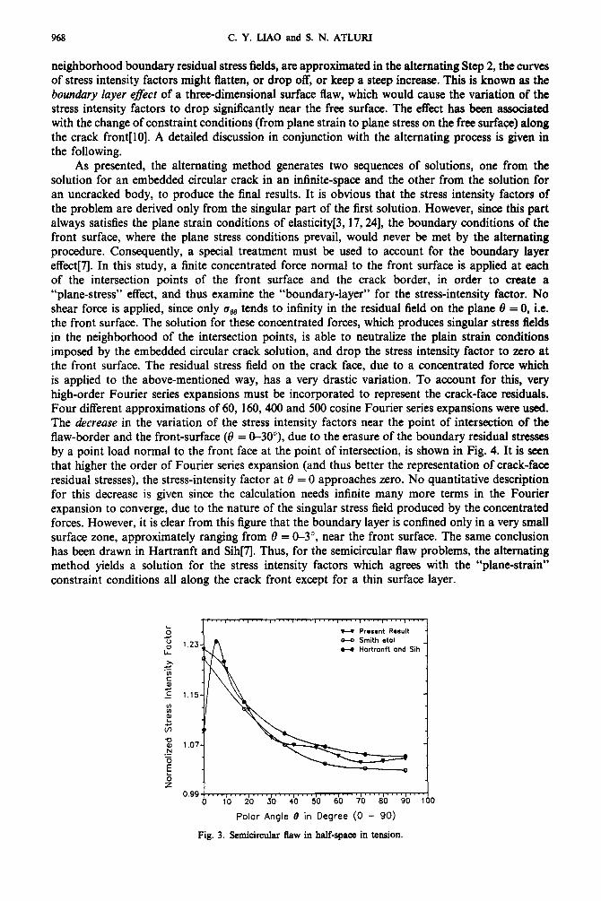
Figure 3 shows the normalized stress intensity factors for the semicircular crack in a semi-infinite solid. All three curves predict a minimum increase in stress intensity factor (from that of an embedded circular flaw in an infinity-body which is normalized to be unity) at the deepest point and a maximum increase at near the front surface. In general, all these results fall in a band of 3% width. The solution of Smith et al.[4] represents the lower bound of the band because of the smaller Poisson’s ratio (0.25 vs 0.3) used in their calculation. The present result predicts a wavy behavior similar to that in Ruiz and Epstein’s experimental work[l5], and Hartranft and Sih[7J predicted a sharp drop in the stress intensity factor variation in a thin surface layer of the surface flaw. It is interesting to notice the different characteristics of the three curves near the front surface. Based on how the points of intersection of the crack border with the front surface, and their
EFM W-L
968 C. Y. LIAO and S. N. ATLURI
neighborhood boundary residual stress fields, are approximated in the alternating Step 2, the curves of stress intensity factors might flatten, or drop off, or keep a steep increase. This is known as the boundary layer e&t of a three-dimensional surface flaw, which would cause the variation of the stress intensity factors to drop significantly near the free surface. The effect has been associated with the change of constraint conditions (from plane strain to plane stress on the free surface) along the crack front[lO]. A detailed discussion in conjunction with the alternating process is given in the following.
As presented, the alternating method generates two sequences of solutions, one from the solution for an embedded circular crack in an infinite-space and the other from the solution for an untracked body, to produce the final results. It is obvious that the stress intensity factors of the problem are derived only from the singular part of the first solution. However, since this part always satisfies the plane strain conditions of elasticity[3, 17,241, the boundary conditions of the front surface, where the plane stress conditions prevail, would never be met by the alternating procedure. Consequently, a special treatment must be used to account for the boundary layer effect[7l. In this study, a finite concentrated force normal to the front surface is applied at each of the intersection points of the front surface and the crack border, in order to create a “plane-stress” effect, and thus examine the “boundary-layer” for the stress-intensity factor. No shear force is applied, since only cBB tends to infinity in the residual field on the plane f3 = 0, i.e. the front surface. The solution for these concentrated forces, which produces singular stress fields in the neighborhood of the intersection points, is able to neutralize the plain strain conditions imposed by the embedded circular crack solution, and drop the stress intensity factor to zero at the front surface. The residual stress field on the crack face, due to a concentrated force which is applied to the above-mentioned way, has a very drastic variation. To account for this, very high-order Fourier series expansions must be incorporated to represent the crack-face residuals. Four different approximations of 60, 160,400 and 500 cosine Fourier series expansions were used. The decrease in the variation of the stress intensity factors near the point of intersection of the flaw-border and the front-surface (13 = O-30”), due to the erasure of the boundary residual stresses by a point load normal to the front face at the point of intersection, is shown in Fig. 4. It is seen that higher the order of Fourier series expansion (and thus better the representation of crack-face residual stresses), the stress-intensity factor at 8 = 0 approaches zero. No quantitative description for this decrease is given since the calculation needs infinite many more terms in the Fourier expansion to converge, due to the nature of the singular stress field produced by the concentrated forces. However, it is clear from this figure that the boundary layer is confined only in a very small surface zone, approximately ranging from 0 = O-3”, near the front surface. The same conclusion has been drawn in Hartranft and Sih[l. Thus, for the semicircular flaw problems, the alternating method yields a solution for the stress intensity factors which agrees with the “plane-strain” constraint conditions all along the crack front except for a thin surface layer.
b H Present Result
z 1.23 O-0 Smith eta1
9 H Hartronft and Sih
x L
E
2 + 1.15
E I ci 0 x
1.07 ‘Z
[
z 0.99
0
Polar Angle 0 in Degree (0 - 90)
Fig. 3. Semicircular flaw in half-spaca in tension.

SIF variation along a surface flaw 969
a-a W&Term Cosines w 160-Term cosinse e-0 400-Term Cosines FT SOO-term Cosinad
0 2 4 6 8 10 12 14 16
Polar Angle @ in Degree (0 - 15)
Fig. 4. Approximate boundary layer effect.
6.2. Crack in a bite-thic~ess plate, simple tension
The solution of a semicircular crack in a finite-thickness plate subjected to tension has to include the interactions between the .front and back boundary surfaces as well as those between these surfaces and the crack face. The introduction of the alternating loop for the “boundary- surfaces” interactions increases the required computing time, but the ~sadvan~ge is offset by a gain in accuracy in the stress intensity factors. Various problems with different crack depth to plate thickness ratios have been computed. Figures 5-8 show the numerical results of 0.2, 0.4, 0.6 and 0.8 depth to thickness ratios. In these figures, the minimums of the stress intensity factor curves occur at the deepest point and the maxim~s occur at near the front surface, and the finite-thickness magnification factor is more pronounced as the plate becomes thinner. Generally speaking, the present results agree with the well accepted FEN results of Newman and Raju[13] for the inside part of the surface flaw, i.e. for 8 = 30-90”. For the outside part (6 = O-30’), the present solution is higher than that of Newman and Raju. The gap gets wider in the case of larger a/t ratios (maximum difference is 8% for a,& = 0.2 and 16% for a/r = 0.8). The discrepancies between these two studies could be due to the nodal force scheme used in ref.[l3] which would predict a “plane-stress” solution, and thus a lower solution, for the stress intensity factors in the outer part of the flaw.
Two experimental works based on the photoelastic stress freezing technique are cited in this paper. The work of Ruiz and Epstein[lS] is included in Fig. 5 for crack of small a/t ratio, and the work of Smith and Kirby[l4] is shown in Fig. 6 for the “benchmark” crack depth. Ruiz and Epstein’s[I5] ex~~mental data curve predicts the boundary layer effect, as well as the wave-like characteristics of the present results. Smith and Kirby[l4] do not consider the boundary effect and provide only a set of scattered data points. Results of both numerical studies fall in the experimental data cu~e/scatter if the incompressibility (Poisson’s ratio = 0.5) effect of the phot~l~tic materials is not corrected.
As a final note, the differences between the numerical results of the current and previous methods are shown in Fig. 8. The present result has a 32% increase on the front surface and a 3% decrease at the rna~rn~ fIaw depth, from the result of Smith and Alavi[S].
6.3. Crack in a finite-thickness plate, pure bending
The solution process of a semicircular crack in a finite-thickness plate subjected to bending is similar to the process in Example 6.2. Both bounda~~ounda~ and ~unda~~rack inter- actions must be included. The prescribed pressure on the crack face is generated by combining a constant load and a linear varying load such that the neutral axis coincides with the center line of the plate thickness. Figures 9-12 show the numerical results of various depth to thickness ratios. The minima occur at the deepest point and the maxima occur at the front surface in these figures, as in the uniform tension case. On the other hand, the stress intensity factor variation drops

Pola
f A
ngle
8
in
Qeg
rCX
(0
-
90)
Fig.
5.
Sem
iciF
cub
fiaw
und
er
tens
ion,
a/
t =
0.2
.
Po
lar
An
gle
B
in
Deg
ree
(0
- 90
)
Fig
. 7.
S
emic
ircul
ar
flaw
und
er t
ensi
an,
a/t
= 0
.5.

t.26
t?
;; 9 0-
Q
New
man
an
d Ra
ju
1.06
W
Ru
iz
ond
Epst
ein
x .tl E 2
0.90
m
3 $ 0.
72
-cJ 8 ‘%
0.54
E ij z
0.36
6
lb
20
$0
40
so
7b
60
9b
1 ci
o P
ola
r A
ng
le
B i
n
Deg
ree
(0
- 9D
)
Fig
. 9.
f3
emic
irct
iar
flaw
un
der
ben
din
g,
a/f
= 0.
2.
o-o
Naw
moo
ond
Ro
ju
Po
ior
An
gle
6
in
Deg
ree
(0
- 90
)
Fig.
Il
. !J
emic
ireu
lar
flaw
und
er
bend
ing,
a/
t =
0.5.
0.30
+~~~
, , .
* I
. ,1
.1
.
. .
0 10
20
30
40
. ,
I. I
, *
. ,
. . $.
7--j
50
60
70
80
90
100
Po
lar
An
gle
6
in
Deg
ree
(0
- 90
)
Fig.
IO
. L
3em
kird
ar
fiaw
und
er
bend
ing,
a/
t =
0.4
.
Po
lar
An
gie
0
in
Deg
ree
(0
- 90
)
Fig.
12
. Se
snki
rcuI
ar
flaw
und
er
bend
ing,
a/
t =
0.8.

972 C. Y. LIAO and S. N. ATLURI
from the high at the front surface more sharply in the case of bending. This is due to the steeper stress gradient for a bending load. Consequently, higher stress intensity factors are obtained for the case of smaller depth to thickness ratios, as opposed to the trend in the solutions for uniform tension loads. The present numerical results are identical with those of Newman and Raju[l3] for 19 = 30-90”, and predict a maximum difference of 10% for a/t = 0.2 and 26% for a/t = 0.8, for 8 = O-30”. The differences could be attributed to the same reason discussed previously. It should be noticed that the numerical results for bending loads do not have a wavy variation, as opposed to the case of tensile loads.
6.4. Convergence and accuracy
A study on the convergence of the numerical results with respect to various parameters is presented here. The best values for these parameters are derived and compared with the selected values in the beginning paragraph of Example 1. For simplicity, the semi-infinite problem subjected to uniform tension is chosen as a basis for the study. The general properties of convergence should still be revealed in this case since the front surface effect is far more significant than that of the back surface. The convergence properties for the tension and bending problems are assumed to be similar.
In carrying out this study, several parameters of the alternating procedure are varied, and the stress intensity factors are computed and recorded accordingly. Differences among the results may then be used to determine the quality of convergence. The level of mesh refinement on the front surface is the first parameter to be examined. Four meshes of 79, 140, 205, 294 cells, respectively, are tested. The corresponding stress intensity factors are tabulated in Table 1. A near monotonic convergence is observed among these results. The maximum stress intensity factor starts from 1.191 for the mesh of 79 cells and ends with 1.221 for the mesh of 294 cells. The selected mesh of 205 cells is found to yield very accurate results.
The order of curve fitting for the crack face pressure is checked> next. This involves three parameters-the refinement of curve fitting grid, the order of radial pressure variations and the number of terms in the Fourier expansion (= order of the Bessel functions). Table 2 gives the results
Table 1. Normalized stress intensity for different levels of mesh refinement on the front surface
Polar angle Number of rectangles on the front surface 0 (degrees) 79 140 205 294
0 1.191 1.205 1.223 1.221 :o” 1.167 1.117 1.177 1.121 1.191 1.126 1.126 1.190
30 1.079 1.080 1.081 1.081 40 1.066 1.067 1.069 1.069 50 1.060 1.062 1.065 1.064 60 1.048 1.050 1.051 1.051 70 1.040 1.040 1.040 1.040 80 1.041 1.042 1.043 1.043 90 1.043 1.045 1.047 1.047
Table 2. Normalized stress intensity for different curve-fitting grids on the crack face
Polar angle
6 (degrees)
0 10 20
: z
70 80 90
Number of nodes in the radial and circumferential directions
5 x 24 10 x 60 10x 100 20x200
1.191 1.220 1.223 1.223 1.168 1.189 1.191 1.191 1.120 1.125 1.126 1.126
1.066 1.082 1.081 1.069 1.081 1.069 1.081 1.069 1.059 1.049 1.051 1.064 1.065 1.051 1.051 1.065
1 .&I2 1.040 1.040 1:041 1.041 1.043 1.043 1.043 1.043 1.047 1.047 1.047
SE variation along a surface llaw
Table 3. Normalized stress intensity for different order of radial pressure variations on the crack face
913
Polar angle 0 (dearees) second
Order of polynomial third fourth fifth
0 1.219 1.222 1.223 1.223 10 1.187 1.191 1.191 1.191 20 1.123 1.126 1.126 1.126 30 1.080 1.081 1.081 1.081 40 1.069 1.069 1.069 1.069 50 1.065 1.064 1.065 1.065 60 1.051 1.051 1.051 1.051 70 1.040 1.040 1.040 1.041 80 1.043 1.043 1.043 1.043 90 1.047 1.047 1.047 1.047
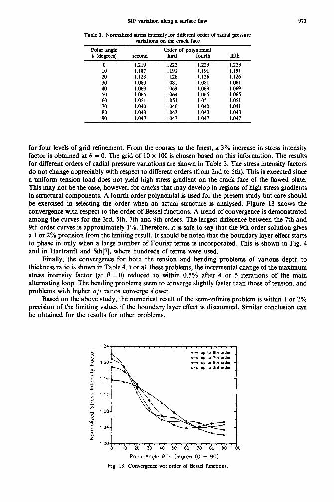
for four levels of grid refinement. From the coarses to the finest, a 3% increase in stress intensity factor is obtained at 8 = 0. The grid of 10 x 100 is chosen based on this information. The results for different orders of radial pressure variations are shown in Table 3. The stress intensity factors do not change appreciably with respect to different orders (from 2nd to 5th). This is expected since a uniform tension load does not yield high stress gradient on the crack face of the flawed plate. This may not be the case, however, for cracks that may develop in regions of high stress gradients in structural components. A fourth order polynomial is used for the present study but care should be exercised in selecting the order when an actual structure is analysed. Figure 13 shows the convergence with respect to the order of Bessel functions. A trend of convergence is demonstrated among the curves for the 3rd, 5th, 7th and 9th orders. The largest difference between the 7th and 9th order curves is approximately 1%. Therefore, it is safe to say that the 9th order solution gives a 1 or 2% precision from the limiting result. It should be noted that the boundary layer effect starts to phase in only when a large number of Fourier terms is incorporated. This is shown in Fig. 4 and in Hartranft and Sih[7], where hundreds of terms were used.
Finally, the convergence for both the tension and bending problems of various depth to thickness ratio is shown in Table 4. For all these problems, the incremental change of the maximum stress intensity factor (at 8 = 0) reduced to within 0.5% after 4 or 5 iterations of the main alternating loop. The bending problems seem to converge slightly faster than those of tension, and problems with higher a/t ratios converge slower.
Based on the above study, the numerical result of the semi-infinite problem is within 1 or 2% precision of the limiting values if the boundary layer effect is discounted. Similar conclusion can be obtained for the results for other problems.
1.24
'0 z 9 1.20
x .C
z 1.16 0) z -
w E 1.12
$ # m 1.06
x 'Z
z 1.04
b z
1.00 0 10 20 30 40 50 60 70 80 90 100
Polor Angie 0 in Degree (0 - 90)
Fig. 13. Convergence wrt order of Bessel functions.

Tab
le
4.
Con
verg
ence
ra
tes
for
the
tens
ion
and
bend
ing
prob
lem
s of
va
riou
s cr
ack-
dept
h to
pl
ate-
thic
knes
s ra
tios
Iter
atio
n C
hang
e of
th
e no
mal
ized
st
ress
-int
ensi
ty
fact
or
at
0 =
0 fo
r o/
t of
N
mbe
r of
Se
mi-
infi
nite
0.
2 0.
4 0.
6 0.
8 0.
2 0.
4 0.
6 0.
8 M
ain
bOD
T
ensi
on
Ben
ding
0 1.
00
1.00
1.
00
1.00
1.
00
1.00
1.
00
1.00
1.
00
1 0.
1789
0.
1902
0.
2459
0.
3248
0.
4118
0.
1355
0.
1317
0.
1441
0.
1676
2
0.35
14
x 10
-l
0.38
63
x lo
-’
0.58
34
x 10
-l
0.95
65
x 10
-l
0.14
75
0.25
25
x IO
-’
0.24
81
x 10
-l
0.28
47
x IO
-’
0.34
58
x IO
-’
3 0.
7115
x
lo-2
0.
8040
x
lo-*
0.
1342
x
IO-’
0.
2705
x
IO-’
0.
4852
x
IO-’
0.
5142
x
IO-*
0.
5397
x
10-2
0.
7340
x
10-Z
0.
1002
x
10-l
4
0.14
46
x 10
-2
0.16
73
x lo
-*
0.30
96
x lo
-’
0.71
56
x lo
-’
0.15
50
x 10
-l
0.11
61
x lO
-2
0.12
21
x lo
-*
0.18
93
x IO
-*
0.30
96
x lO
-2
5 -
- -
0.17
71
x lo
-*
0.47
20
x IO
-*
- -
0.46
46
x IO
-3
0.93
35
x 10
-3

SIF variation along a surface flaw 975
7. SUMMARY AND CONCLUSIONS
A highly accurate alternating procedure, or analytical alternating procedure, has been implemented for computing the stress intensity factors along the crack front of a semicircular or part -circular fraw in a &rite body. As needed, the general solution of embedded circular flaw in an infinite solid and the solution of a half space subjected to constant shear tractions are summarized and discussed. Based on the numerical results for various examples; the following conclusions can be drawn.
(1) For the alternating method using only analytical solutions, both the boundary-boundary as well as the boundary-crack interactions should be considered in order to obtain correct finite-body results.
(2) The alternating method yields a “plain-strain” solution for the stress intensity factors all along the crack front except for a very thin boundary layer. As a result, the present results agree with those of Newman and Raju[l3] only for the inside portion (0 = 30-90”) of the surface flaw, The maximum difference between these two solutions ranges from 8 to 26%, depending on various loading types and crack-depth to plate-thickness ratios.
(3) The stress intensity factor variation along the flaw border has a wavy format for the uniform tension problems, as predicted in the experimental work of Ruiz and Epstein[ 151. For the bending problems, however, the computed stress intensity factors fit in a smooth curve, contrary to the experimental results which have a wavy curve for both tension and bending problems.
(4) Without regard to the boundary layer effect near the point where the surface flaw intersects the front-surface, the present implementation converges to 2% precision within 5 iterations. A convergence study shows that the method is very stable as to changes in various parameters, such as those for mesh refinement and curve fitting.
(5) The boundary layer effect is insignificant when low order curve fitting parameters are used, and is confined in a very small zone (0 = O-3”) near the boundary surface. This effect phases in only if a large number of terms in the Fourier expansion is employed-which makes a routine analysis of the “boundary-layer effect” prohibitively expensive for practical problems.
Acknowledgement-This work was supported by the U.S. Office of Naval Research, with Dr Y. Rajapakse as the program official. This support, as well as the contribution of Professor H. Q. Zhong, are gratefully acknowleda;ed. The assistance of MS Deanna Winkler is also acknowledged with thanks.
111
PI
[31
141
[51
[el
I71
[81
[91
WI
IllI
1:;;
u41
REFERENCES
R. J. Gran, F. D. Orazio, P. C, Paris, G. R. Irwin and R. Her&erg, Investigation and Analysis Development of Early Life Aircraft Structural Failures. Technical Report AFFL-TR-70-149, Wright-Patterson Air Force, Ohio (1971). I. S. Raju, S. N. Atluri and J. C. Newman, Jr, Stress-intensity factors for small surface and corner cracks in plates. NASA Technical Memorandum 100599 (1988). F. W. Smith, A. S. Kobayashi and A. F. Emery, Stress intensity factors for penny-shaped cracks, Part I-I&mite solid. J. a@. Me&. 34, 947-952 (1967). F. W. Smith, A. S. Kobayashi and A. F. Emery, Stress intensity factors for penny-shaped cracks, Part 2 -Semi-infinite solid. J. appl. Mech. 34, 953-959 (1967). F. W. Smith and M. J. Alavi, Stress intensity factors for a penny shaped crack in a half space. Engng Fracture Me&. 3, 241-254 (1971). R. W. Thresher and F. W. Smith, Stress intensity factors for a surface crack in a finite solid. J. appl. Me& 39, 195-200 (1972). R. J. Hartranft and G. C. Sih, Alternating method applied to edge and surface crack problems. in &ferkorls of&t&&r and Solutions of Crack Problems (Edited by G. C. Sih), pp. 179-238. Noordhoff International, Leyden (1973). R. C. Shah and A. S. Kobayashi, Stress intensity factors for an elliptical crack under arbitrary normal loading. &gng Fracture Me&, 3, 71-96 (1971). A. S. Kobayashi, A. N. Enetanya and R. C. Shah, Stress intensity factors of elliptical cracks. Prospects of Fracture Mechanics (Edited by G. C. Sih et al.), pp, 525-544. Noordhoff International, Leyden (1975). J. J. McGowan (Ed.), A critical evaluation of numerical solutions to the benchmark surface flaw problem. SESA Monograph (1980). 1. V. Netmtann, Functimal Uperafors--Vol. II. The Geometry of Orthoganal Spaces. Princeton University Press, Princeton (1950) M. K. Kassir and G. C. Sih, Z’hree-Dimensional Crack Problem. Noordhoff International, Leyden (1975). J, C. Newman and I. S. Raju, Analysis of surface cracks in finite plates under tension or bending loads. NASA Technical Paper 1578 (1979). C. W. Smith and G. C. Kirby, Stress intensity distributions and width correction factors for natural cracks approaching “Benchmark” crack depths, Fracture Mechanics, AS7’M STP 833 (Edited by R. J. Sanford), pp. 118-129 (1984).
976 C. Y. LIAO and S. N. ATLURI
[Is] C. Ruiz and J. Epstein, Gn the variation of the stress intensity factor along the front of a surface crack. Znr. J. Fracture 28, 231-238 (1985).
[16] I. N. Sneddon. The distribution of stress in the neighborhood of a crack in an elastic solid. Proc. R. SIX., Secrion A, 187,229260 (1946).
[17] C. Y. Liao, An analysis of three-dimensional circular and semicircular crack problems. Ph.D. Thesis, Georgia Institute of Technology, in preparation.
[18] A. E. H. Love, Gn stress produced in a semi-inSnite solid by pressure on part of the boundary. Plril. Dons. R. Sot. Section A, 228, 378-395 (1929).
[ 191 R. C. Shah and A. S. Kobayashi, Stress intensity factors for an elliptical crack approaching the surface of a semi-infinite solid. Znt. J. Fracture 9, 133-146 (1973).
[20] A. E. H. Love, A Treatise on the Mathematical Theory of Elarlicity. Dover Publication, New York (1944). (211 H. Cross, Analysis of Continuous frames by distributing fixed-end moments. Proc. ASCE, vol. 56, pp. 919-928 (1930). [22] L. V. Kantorovich and V. I. Krylov, Approximare Metho& of Higher Analysis. Wiley, New York (1964). (231 IMSL User’s Manual, IMSL, Inc., Houston (1985). (241 G. C. Sih, A review of the three-dimensional stress problem for a cracked plate. Znr. J. Fracture Me&. 7,3%1 (1971).
(Received 2 February 1989)