STRESS-DEFORMATION AND STRENGTH CHARACTERISTICS OF …
12
59 PROC. OF JSCE, No. 232, DEC. 1974 STRESS-DEFORMATION AND STRENGTH CHARACTERISTICS OF SOIL UNDER THREE DIFFERENT PRINCIPAL STRESSES By Hajime MATSUOKA* and Teruo NAKAI** 1. INTRODUCTION The concept that the deformation of soil is governed by the shear-normal stress ratio on the mobilized plane of soil particles has already been discussed on the basis of the microscopic analysis of the behaviors of soil particles under shear. 5 This discussion originates in an idea that soil is one of the materials to which the frictional law in its broad sense of word applies. In the pre- sent paper, the authors expand the formerly proposed concept2),4 of three mobilized planes (compounded mobilized planes) among the three principal stress axes into a new postulate that a stress plane called "spatial mobilized plane" oc- curs in the three-dimensional stress space. Then, they propsse to verify, with various test data, the fact that stress-strain relationships of soil under three different principal stresses can unique- ly be expressed by interpreting the relationships with respect to this plane. They also propose a new yield condition (failure criterion) of soil that soil yields when the shear-normal stress ratio on this plane has reached a fixed value. 2. SPATIAL MOBILIZED PLANE It has been accepted that sliding of soil parti- cles occurs to the greatest extent in the plane in which the ratio of shear stress to normal stress has the maximum value, i. e., the plane AC (cf. Fig. 1) called "mobilized plane" which is inclined by an angle of (45+ cmo13/2) (whereinmo13= sin-i{(O'1- 7i)/(o1+ O3))) from the direction of the minor principal stress. However, the direction in which the individual soil particles subjected to the three principal stresses o, o'2 and o'3 slide is not necessarily parallel with the intermediate principal stress axis but is believed to be affected also by the intermediate principal stress 62. In this connection, there has been introduced a con- cept of "compounded mobilized planes which is intended to explain the three-dimensional be- haviors of soil particles by assuming other two mobilized planes AB and BC among three prin- cipal stress axes. For the purpose of the present study, the authors introduce a stress plane ABC as the product of the combination of the three mobilized planes AB, BC and CA and give it a provisional designation of "spatial mobilized plane" (abbreviated as "SMP"). SMP, there- fore, is believed to represent the resultant stress plane in which sliding of soil particles takes place to the greatest extent in the three principal stress space. The points at which SMP intersects the three principal stress axes are proportionate to the roats of the respective principal stresses as Fig. 1 Spatial mobilized plane and three mo- bilized planes in three principal stress space. * Dr. Eng., Assistant Professor, Disaster Pre- vention Research Institute, Kyoto Univer- sity. ** M. Eng., Graduate Student, Kyoto Univer- sity.
Transcript of STRESS-DEFORMATION AND STRENGTH CHARACTERISTICS OF …
59
PROC. OF JSCE,
No. 232, DEC. 1974
STRESS-DEFORMATION AND STRENGTH CHARACTERISTICS OF
SOIL UNDER THREE DIFFERENT PRINCIPAL STRESSES
By Hajime MATSUOKA* and Teruo NAKAI**
1. INTRODUCTION
The concept that the deformation of soil is
governed by the shear-normal stress ratio on the mobilized plane of soil particles has already been discussed on the basis of the microscopic analysis of the behaviors of soil particles under shear. 5This discussion originates in an idea that soil is one of the materials to which the frictional law in its broad sense of word applies. In the pre-sent paper, the authors expand the formerly
proposed concept2),4 of three mobilized planes (compounded mobilized planes) among the three principal stress axes into a new postulate that a stress plane called "spatial mobilized plane" oc-curs in the three-dimensional stress space. Then, they propsse to verify, with various test data, the fact that stress-strain relationships of soil under three different principal stresses can unique-ly be expressed by interpreting the relationships with respect to this plane. They also propose a new yield condition (failure criterion) of soil that soil yields when the shear-normal stress ratio on this plane has reached a fixed value.
2. SPATIAL MOBILIZED PLANE
It has been accepted that sliding of soil parti-cles occurs to the greatest extent in the plane in which the ratio of shear stress to normal stress has the maximum value, i. e., the plane AC (cf. Fig. 1) called "mobilized plane" which is inclinedby an angle of (45+ cmo13/2) (whereinmo13=sin-i{(O'1- 7i)/(o1+ O3))) from the direction of theminor principal stress. However, the direction in which the individual soil particles subjected
to the three principal stresses o, o'2 and o'3 slide
is not necessarily parallel with the intermediate
principal stress axis but is believed to be affected also by the intermediate principal stress 62. In
this connection, there has been introduced a con-
cept of "compounded mobilized planes which
is intended to explain the three-dimensional be-
haviors of soil particles by assuming other two
mobilized planes AB and BC among three prin-cipal stress axes. For the purpose of the present study, the authors introduce a stress plane ABC as the product of the combination of the three mobilized planes AB, BC and CA and give it a provisional designation of "spatial mobilized
plane" (abbreviated as "SMP"). SMP, there-fore, is believed to represent the resultant stress
plane in which sliding of soil particles takes place to the greatest extent in the three principal stress space. The points at which SMP intersects the three principal stress axes are proportionate tothe roats of the respective principal stresses as
Fig. 1 Spatial mobilized plane and three mo-
bilized planes in three principal stress
space.
* Dr. Eng., Assistant Professor, Disaster Pre-
vention Research Institute, Kyoto Univer-
sity.** M. Eng., Graduate Student, Kyoto Univer-
sity.
60 H. MATSUOKA and T. NAKAI
shown in Fig. 1, as indicated by the following
equation.
tan (45+mo2.7
/1-(Jlll YmoUV 1-sin
mo23
=(z, =1, 2, 3, i<j) (1)
This resultant stress plane, therefore, is vari-able with possible change in the stresses. The direction consines (a1, a2i a3) of the normal of SMP are expressed as follows.
a1=/J3a2=a3J.l3/ 0112 02J2 0312
(2)
wherein, J1i 12 and J3 are the first, second and third stress invariants which are expressed by the following equations.
J1=01+02+03, J2=0102+0203+030113 = 010203 (3)
Throughout this paper, the term "stress" shall
invariably interpreted as representing "effective
stress. " In this paper, the various test data will
be analyzed with consideration for the stress plane called "spatial mobilized plane (SMP)."
3. STRESS-STRAIN RELATIONSHIPS
BASED ON SMP
The normal stress o and the shear stress z on the spatial mobilized plane (SMP) are express-ed as follows :
σN=σ1・ α21+σ2・α22+σ3・α23=3J3/J2 …… (4)
T=V(61-62)2lliZ2+72-ag)2fl2a3+(a3a1)2a3al
NJ1J2J3-yJ3(5)
The shear-normal stress ratio (r/O'N) on the SMP, therefore, is given by the following equa-tion.
τ/N=√J1J2-9J3/9J (6)
On the assumption that the direction of the
principal stress and that of the principal strain increment are identical, the normal strain incre-
ment dEN and the shear strain increment dr on
the SMP can be given by the following expres-
sions.
dEN=dE1ai+dE2a2+dE3ag=Trtl+st2+rtdi =/V(dci-dcz)2ala2+(dE2dEg)2a2a3+(dcg-dcl)2a3ai
J3/(d1-do2)2+(dE2-dog)2+(dE3-dol)2h Q1CU66Q1
(8)
Under special conditions of triaxial compressionand triaxial extension, r/QN and dEN/dr are givenrespectively by the following equations.
Under triaxial compression condition (62=co anddEz=dE3):
N=2/3(b1/b3-b3/b1)
(9)
dEN6i/cdEg+Vio/ii(dEi/2)dr2(dEi-dE3) (10)
Under triaxial extension condition (6i = ao and dEi=dc2):
T=y3 (VOi/-VUg/6i). (11)
dEN/0'i/a3(dE3/2)+ 4/c3/6idEidr V 2 dEi -de (12)
Here, if the basic stress-strain relationships
derived from the behavior of soil particles on the
mobilized plane and applied to the compounded
mobilized planes2),4) are also valid for this spatial
mobilized plane, then the following equations
should hold on the SMP.
UTT dr(13)
T=EN)+(G=2Bo+f2)UTTY
(14)
By combining Eqs. (13) and (14) and solvingthe differential equation, one obtains the follow-ing equations.
2 -+ln1+ (15)
EN=rInT-1 (16)
wherein, the same symbols (2u,and to) ason the compounded mobilized planes are used on the SMP for simplicity. In the above expres-sions, 2, c, and to denote soil parameters which are determined by the kind and state of soil under test. Of these parameters, ie denotes the frictional coefficient between soil particles (=

Stress-Deformation and Strength Characteristics 61
tan 5 and 2 is the constant having an approxi-mate value of 1. 1-1. 5 to be determined by u. The symbol u' represents a parameter which has to do with the i. nterparticle friction and the gran-ular structure in the initial state of soil. There are fair indications that under the normal gran-ular structure, these three parameters (2, u and u') may be regarded as assuming approximately constant values for a particular soil specimen. The symbol To which denotes the value of r at the maximum compression point of the normal strain EN on the mobilized plane is believed to form a parameter expressing the granular struc-ture of soil. This is a coefficient which varies with the initial void ratio et, the mean effective principal stress am and other factors.
Now, let (al, a2i a3) and (b1, b2, b3) stand for the direction cosines of the strain increments dEN and dr on the SMP respectively, and the conversion of the strain increments dEN and dr on the SMP to the respective principal strain increments dEl, doe and dE3 will be given by the following equa-tion.
yi urdE2 =dEN+2 (i=1, 2, 3) (17)
In this equation, ai is found from Eq. (2) on condition that the direction of the principal stress and that of the principal strain increment are identical. In addition, the direction cosines are of a nature such as to satisfy bi + b2 + b3 =1 and the normality condition gives rise to al b1+a2 b2+a3 b3 =0. One more condition is required becausethere are three unknowns hl, b2 and b3 while there are two conditional equations. Under the triaxial compression condition, the following equa-tions are evolved from the condition of b2 = b3.
de1=46N+√7・ √σ1/σ3・dr/2
de3=den-√1/2・ √∂1/δf・dr2/2
(18)
Since application of X= z/0'N to Eqs. (13) and
(15) leads to the following equations,
dγ=μ0-μ ・ex(X-u)/dX
deN=u-X/11dγ
Eq. (18) is integrable and the relationship be-tween the principal stresses and the principal strains can be given by the following equations.
ε1=X=XX=0=γ10[F1(X)1c-F1(0)1T.c」
ε3=X4d=γ0[F3(X)1cT1(0)1, c.]
(19)
Wherein, X-z/6N= vG(al/63-Q3/Q1)
F1(x)1T.c=exp/1/X+(3/4-1/10)
-9(u-u)√2/x+1/2+4/10
-5(μ-μ)+9(1-10)}
F3(x)IT. c. =exp (29. X2+(-1/20
+9(u-u)・x-2+7/10
6(μ-μ)-9(u-u)/104)
It should be noted that approximation is involv-
ed in the course of the calculation of this inte-
gration. Under the triaxial extension condition, the condition b1= b2 gives rise to the following
equations.
d61=den+1/2・ √σ1/σ3・dr/2
d63=d6N√2・ √σ3/σ・dr/2
(20)
The following expressions are derived from integrating Eq. (20) similarly to the calculation under the triaxial compression conditions.
El -dEl=rLFl(X)IT. E. -Fl(o)IT. Ej
ε3=14-F3X)1.E-F2(0)iFE]
(21)
Wherein, 1=Z6nr= V O16g/63/Q2)
Fl(X) IT. E. =eXp f nn J/ n X2-+n
-9(u-u1)x+11-1+
-3(u-u)/8+9(u-u)2/16/2
2 J 1F3(x)ET. E. =exp (- --16 2+4.
+9-10})・X-1/2-181+1/10
3(μ'-μ)9(μ1-μ)2
48√2
Also in this case, approximation is involved in the course of the calculation of the integration. Examination of Eqs. (19) and (21) reveals that the volumetric strain Ev is expressed by the same equation under triaxial compression and triaxial extension conditions alike. Under the plane strain conditions, the following equations are derived from d2=0,

62 H. MATSUOKA and T. NAKAI
aiaEN+yaia3(1-a2)(aTI2)L-aia2a3(aEN)4dE1=
a3 dEN-ai a3 (1-a2) (dr/2)2-ai a2 a3 (dEN)2dE3-2
(22)
Where three different principal stresses are ex-
erted, the respective principal strain increments
d1, dE2 and dE3 are given by the following expres-
sions on condition that the direction of r and that
of dr on the SMP are identical.
u%f2-Jf3 UTdE2=dEN+-
=d+No Z-o'N d(i=1, 2, 3) (23)
It follows as a natural consequence that so far as the stress conditions are known, the respective principal strains E1, E2 and E3 can be found by having these principal strain increments integrat-ed along the stress paths. It is also checked that these principal strains calculated from the concept of this spatial mobilized plane agree well with those derived from the former concept of the compounded mobilized planes.
For comparison, a study will be made here with respect to an octahedral plane. Since the direc-tion cosines of the normal of an octahedral plane are (1/V'3, 1/'/3, 1//3), the shear-normal stress ratio (z/6N)oct and the normal-shear stain incre-ment ratio (dEN/dr)OCt on this plane are given by the following equations.
(r oct)
o(61-02)2+lQ2-'(73)2+(o- -Q1261+Q2+Q3
roct
6m
(24)
(ddγ)oct=2√(dε1-dε2)+(d63-dε1)2
dev
/3・dγoct(25)
wherein,
Toct= Z v'(Ui-02)2+(02-0.3)2+(0'3-61)2
Qm=3(Q1+U2+Q3)
dEv=dE1+dc2+dc3
droct-.Z(dEl-dE2)2-f-(dE2-dE3)2-}-(dE3-dEl)2
Under the triaxial compression and triaxial ex-tension conditions alike, Eqs. (24) and (25) are evolved respectively as follows.
T-yG61-63
QN oct 3 Qm(26)
GLEN 1 uEy
d)24/2 (dEi-dEa) (27)
The variable (Q1-63)/Qm appearing in Eq. (26) and the variable dEv/(dEi-dE3) in Eq. (27) are those which are frequently employed by the Cambridge school and others as parameters to govern the mechanical properties of soils), 7) The question arises as to which set of parameters can more accurately express the properties of soil, those applicable to the octahedral plane or those appli-cable to the spatial mobilized plane (SMP). This
question will be discussed on the basis of test data in the following chapters.
4. VERIFICATION OF PROPOSED EX- PRESSIONS BY TEST DATA
4. 1 Verification of Relationship between Shear- normal Stress Ratio (z/UN) and Normal-shear
Strain Increment Ratio (dEN/dr) on Spatial Mobilized Plane
In this section, the authors proceed to verify, by using various test data, the basic stress-strain relationships on the spatial mobilized plane and the principal stress-principal strain relationships dealt with in the preceding chapter. As the first step, Eq. (13) indicating the z/QN-dEN/dr relation-ship on the spatial mobilized plane will be dis-cussed. Fig. 2 shows the results of the triaxial compression test ("O" marks: 6m=1. 0 kg/cm2 and initial void ratio e1=0. 889), the triaxial extension
Fig. 2 Relationship between n/UN and deN/dr on spatial mobilized plane in triaxial
compression, triaxial extension and
plane strain tests on Toyoura sand,
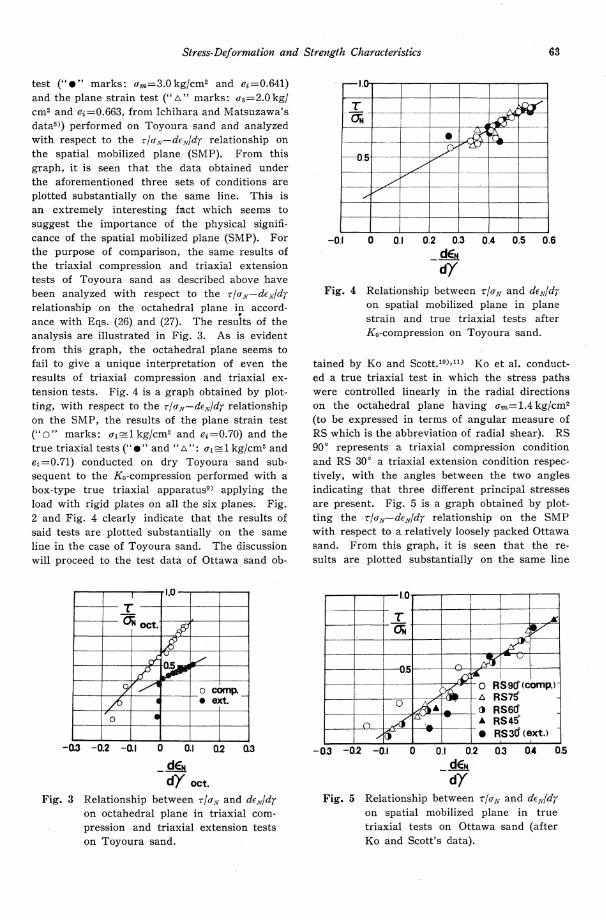
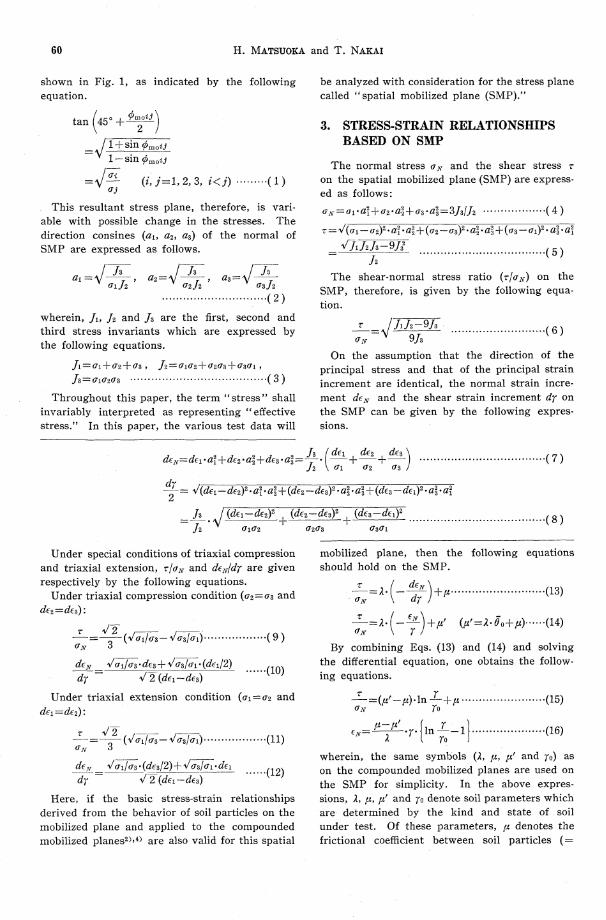
Stress-Deformation and Strength Characteristics 63
test ("O" marks: m=3.0kg/cm2 and ei=0.641)and the plane strain test ("O" marks: a'3 =2.0kg/cm2 and e=0. 663, from Ichihara and Matsuzawa'sdata8)) performed on Toyoura sand and analyzed with respect to the Z'la'N-dENldr relationship on the spatial mobilized plane (SMP). From this
graph, it is seen that the data obtained under the aforementioned three sets of conditions are
plotted substantially on the same line. This is an extremely interesting fact which seems to suggest the importance of the physical signifi-cance of the spatial mobilized plane (SMP). For the purpose of comparison, the same results of the triaxial compression and triaxial extension tests of Toyoura sand as described above have been analyzed with respect to the z/UN-dEN/dr relationship on the octahedral plane in accord-ance with Eqs. (26) and (27). The results of the analysis are illustrated in Fig. 3. As is evident from this graph, the octahedral plane seems to fail to give a unique interpretation of even the results of triaxial compression and triaxial ex-tension tests. Fig. 4 is a graph obtained by plot-ting, with respect to the TI crN-dENldr relationship on the SMP, the results of the plane strain test
("O" marks: Q1 =1 kg/cm2 and e=0. 70) and thetrue triaxial tests ("O" and "O": Q1=1kg/cm2 and
e=0. 71) conducted on dry Toyoura sand sub-sequent to the K0-compression performed with a box-type true triaxial apparatus9) applying the load with rigid plates on all the six planes. Fig. 2 and Fig. 4 clearly indicate that the results of said tests are plotted substantially on the same line in the case of Toyoura sand. The discussion will proceed to the test data of Ottawa sand ob-
tained by Ko and Scott.10),11) Ko et al. conduct-ed a true triaxial test in which the stress paths were controlled linearly in the radial directions on the octahedral plane having a'm=1. 4 kg/cm2
(to be expressed in terms of angular measure of RS which is the abbreviation of radial shear). RS 90 represents a triaxial compression condition and RS 30 a triaxial extension condition respec-tively, with the angles between the two angles indicating that three different principal stresses are present. Fig. 5 is a graph obtained by plot-ting the v/UN-dEN/dr relationship on the SMP with respect to a relatively loosely packed Ottawa sand. From this graph, it is seen that the re-sults are plotted substantially on the same line
Fig. 3 Relationship between z/QN and dEN/dr on octahedral plane in triaxial com-
pression and triaxial extension tests on Toyoura sand.
Fig. 4 Relationship between v/UN and dENldr on spatial mobilized plane in plane strain and true triaxial tests after Ko-compression on Toyoura sand.
Fig. 5 Relationship between z/UN and dENldr on spatial mobilized plane in true
triaxial tests on Ottawa sand (after Ko and Scott's data).
64 II. MATSUOKA and T. NAKAI
under stress conditions ranging from those of tri-axial compression to those of triaxial extension, though with a slight extent of dispersion in plot-ting. The foregoing test data indicate that what the authors designate as "spatial mobilized plane" constitutes an interesting stress plane which pro-vides a unique interpretation of the stress-dilatan-cy characteristics under three different principal stresses. In accordance with Eq. (13), the ordi-nate intercepts of the graphs of Figs. 2, 4 and 5 are found to correspond to the interparticle fric-tion coefficients and the linear gradients to 2. The values (1.1-1.3) of the linear gradient A in-dicated in these graphs are found to be adequate for the values of A to be calculated with respect to the values (0.20-0.25) of 3)
4.2 Verification of Relationship between Shear-normal Stress Ratio (z/UN) and Normal-shear
Strain Ratio (EN/r) on STOMP
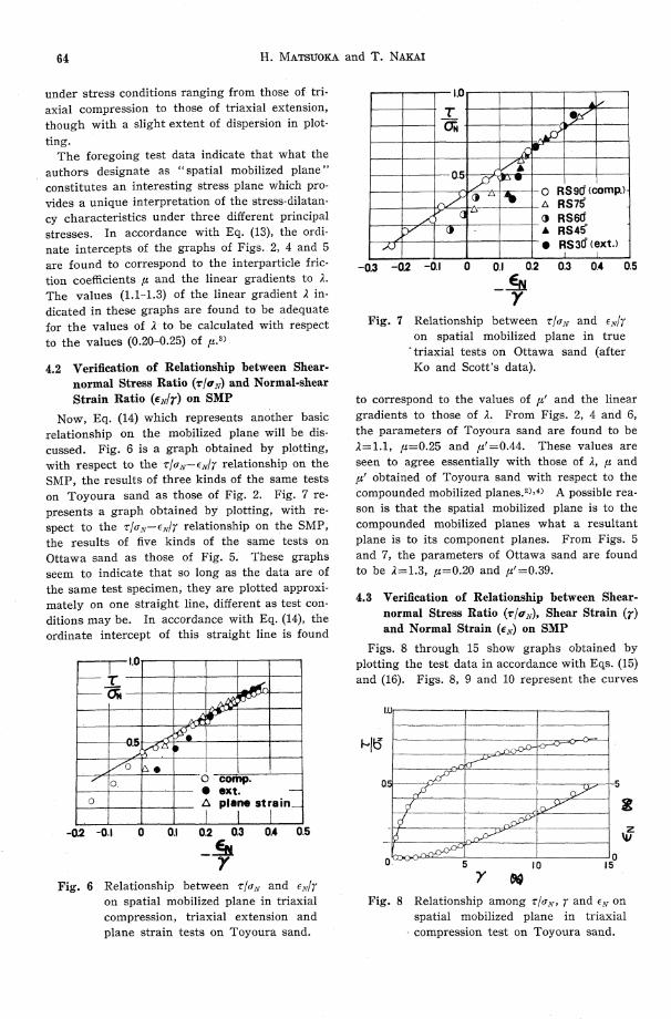
Now, Eq. (14) which represents another basic relationship on the mobilized plane will be dis-cussed. Fig. 6 is a graph obtained by plotting, with respect to the r/6N-E/7 relationship on the SMP, the results of three kinds of the same tests on Toyoura sand as those of Fig. 2. Fig. 7 re-
presents a graph obtained by plotting, with re-spect to the T/UN-EN/r relationship on the SMP; the results of five kinds of the same tests on Ottawa sand as those of Fig. 5. These graphs seem to indicate that so long as the data are of the same test specimen, they are plotted approxi-mately on one straight line, different as test con-ditions may be. In accordance with Eq. (14), the ordinate intercept of this straight line is found
to correspond to the values of 'C' and the linear
gradients to those of A. From Figs. 2, 4 and 6, the parameters of Toyoura sand are found to be 2=1.1, a=0.25 and 'C'=0.44. These values are seen to agree essentially with those of A, and u' obtained of Toyoura sand with respect to the compounded mobilized planes. 2),4) A possible rea-son is that the spatial mobilized plane is to the compounded mobilized planes what a resultant
plane is to its component planes. From Figs. 5 and 7, the parameters of Ottawa sand are found to be 2=1.3, u=0.20 and u'=0.39.
4. 3 Verification of Relationship between Shear-normal Stress Ratio (r/UN), Shear Strain (r) and Normal Strain (EN) on SMP
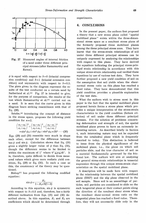
Figs. 8 through. 15 show graphs obtained by
plotting the test data in accordance with Eqs. (15) and (16). Figs. 8, 9 and 10 represent the curves
Fig. 6 Relationship between r/0N and EN/ron spatial mobilized plane in triaxial compression, triaxial extension and
plane strain tests on Toyoura sand.
Fig. 7 Relationship between T/6N and EN/r on spatial mobilized plane in true triaxial tests on Ottawa sand (after Ko and Scott's data).
Fig. 8 Relationship among V/-N, r and EN on spatial mobilized plane in triaxialcompression test on Toyoura sand.
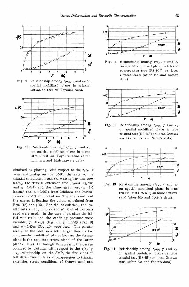
Stress-Deformation and Strength Characteristics 65
obtained by plotting, with respect to the TIN-r-EN relationship on the SMP, the data of the
triaxial compression test (om=1.0kg/cm2 and e2=0.889), the triaxial extension test (im=3.0kg/cm2and ei=0.641) and the plane strain test (03=2.0kg/cm2 and ei=0.663: from Ichihara and Matsu-zawa's data8)) conducted on Toyoura sand and the curves indicating the values calculated from Eqs. (15) and (16). For the calculation, the co-efficients l=1.1, u=0.25 and u'=0.44 of Toyoura sand were used. In the case of r0, since the ini-tial void ratio and the confining pressure were variable, r0=0.70% (Fig. 8), r0=0.25 (Fig. 9)and r0=0.45 (Fig. 10) were used. The param-eter r0 on the SMP is a little larger than on the compounded mobilized planes because the former plane is the resultant stress plane of the latter planes. Figs. 11 through 15 represent the curves obtained by plotting, with respect to the r/N-r-EN relationship on the SMP, the five kinds of
test data covering triaxial compression to triaxial extension stress conditions of Ottawa sand and
Fig. 9 Relationship among T/UN, r and EN on spatial mobilized plane in triaxial extension test on Toyoura sand.
Fig. 10 Relationship among TIQN, r and ENon spatial mobilized plane in planestrain test on Toyoura sand (afterIchihara and Matsuzawa's data).
Fig. 11 Relationship among T/UN, r and ENon spatial mobilized plane in triaxialcompression test (RS 90) on looseOttawa sand (after Ko and Scott'sdata).
Fig. 12 Relationship among V/CN, r and ENon spatial mobilized plane in truetriaxial test (RS 75) on loose Ottawasand (after Ko and Scott's data).
Fig. 13 Relationship among V/7N, r and EN on spatial mobilized plane in true
triaxial test (RS 60) on loose Ottawa sand (after Ko and Scott's data).
Fig. 14 Relationship among zlow, r and EN on spatial mobilized plane in true
triaxial test (RS 45) on loose Ottawa sand (after Ko and Scott's data).

66 H. MATSUOKA and T. NAKAI
the curves indicating the values calculated from Eqs. (15) and (16). For the calculation, the co-efficients A=1. 3, p=0. 20 and p'=0. 39 of Ottawa sand were used. With respect to To, since the initial granular structure differed to some extent,
o=0. 13% (Fig. 11), ro=0. 080 (Fig. 12), ro=0. 100 (Fig. 13), ro = 0. 04 % (Fig. 14) and ro = 0. 13 o (Fig. 15) were used. Here, these values of ro are de-termined from the definition that ro is r at the maximum compression point of the normal strain EN on the mobilized plane and r/UN equals to p at r=ro. Though the coefficient To is considered to serve as a parameter for the evaluation of soil structure, the accurate determination of this pa-rameter is an extremely difficult task. In the elucidation of stress-strain relationships of soil, however, such parameters as involved in the eval-uation of soil structure are by all means neces-sary. It can be expected from comparison of Figs. 11, 12, 13 and 15 that the values of To are nearly constant under the same mean effective
principal stress and the almost same density. (Fig. 14 appears to represent a case in which the structure is slightly more compact than in the other four cases.) It should be noted at this
point that, if the initial soil structure is the same, the stress-strain characteristics under three dif-ferent principal stresses can be uniquely express-ed by plotting with respect to the relationships on the spatial mobilized plane.
4. 4 Verification of Relationship between Princi-
pal Stress Ratios and Principal Strains Here, the relationship between the principal
stress ratios and the principal strains under three different principal stresses as derived through the stress-strain relationships on the spatial mobilized
plane will be discussed. Figs. 16, 17 and 18 re-present the curves obtained by plotting, with re-
spect to the relationship between the principal stress ratio (En /a'3) and the principal strains (E1 and E3), the data of the triaxial compression test
(U, n=1. 0 kg/cm2 and ei =0. 889), the triaxial exten-sion test (Erm=3. 0 kg/cm2 and e=0. 641) and the
plane strain test (o 3 = 2. 0 kg/cm2 and ei = 0. 663 : from Ichihara and Matsuzawa's data8)) on Toyo-ura sand and the curves indicating the values
Fig. 15 Relationship among Z/EN, r and EN on spatial mobilized plane in triaxial
extension test (RS 30) on loose Ottawa sand (after Ko and Scott's
data).
Fig. 16 Relationship among E1 and E3
in triaxial compression test on Toyo-
ura sand.
Fig. 17 Relationship among El/a3, c1 and E3 in triaxial extension test on Toyoura
sand.
Fig. 18 Relationship among a'1/a'3, E1 and E3 in plane strain test on Toyoura sand
(after Ichihara and Matsuzawa's data).

Stress-Deformation and Strength Characteristics 67
calculated from Eqs. (19), (21) and (22). For the calculation, the coefficients A=1. 1u=0. 25, 0. 44 and O=0. 70% (Fig. 16), ro =O. 25% (Fig. 17)and o:0. 45% (Fig. 18) were used. Figs. 19 and 20 show the results of the plane strain test (r11 kg/cm2 and ei=0. 70) and those of the true tri-axial test (ei 1 kg/cm2 and e1 =O. 71) on dry Toyo-ura sand subsequent to K0-compression by use of a box-type true triaxial test apparatus.9) In the
graphs, the curves in solid line are those of the values calculated from Eqs. (22) and (23). Since the shear normally starts from the K0-compres-sion state in this test apparatus, the curves of calculated values are translated as illustrated in the diagrams to facilitate comparison with the curves of measured values. This translation is based on the idea that the sample in this test apparatus has already been subjected to a magni-tude of shear which corresponds to the initial
principal stress ratio due to the K0-compression. For the calculation, the coefficients A=1. 2, u0. 25, 1u'=0. 44 and ro = 0. 23 o (Fig. 19) and ro=0. 18% (Fig. 20) were used. Figs. 21 through 25represent the curves obtained by plotting, with respect to the relationship between the principal stress ratio (61/Q3) and the principal strains. (cl, E2and c3), the five kinds of test data covering tri-axial compression to triaxial extension stress con-
Fig. 19 Relationship among Ql/Q3, E1 and E3 in plane strain test after K0-com-
pression on Toyoura sand.
Fig. 20 Relationship among Q1/Q3, e1 and c3 in true triaxial test after K0-com-
pression on Toyoura sand.
Fig. 21 Relationship among 61/e3, cl and Eg in triaxial compression test (RS 90)
on loose Ottawa sand (after Ko and Scott's data).
Fig. 22 Relationship among o'1/es, E1 and c3 in true triaxial test (RS 75) on loose
Ottawa sand (after Ko and Scott's data).
Fig. 23 Relationship among el/63i ci and E3 in true triaxial test (RS 60) on loose
Ottawa sand (after Ko and Scott's data).

68 H. MATSUOKA and T. NAKAI
ditions of Ottawa sand and the curves indicating the values calculated from Eq. (23). For the cal-culation, the coefficients 2=1.3, u=0.20, i'=0.39,
ro=0.130 (Fig. 21), ro=0.080 (Fig. 22), r0=0.10%(Fig. 23), r0=0.04% (Fig. 24) and r0=0.13% (Fig.25) were used.
From the foregoing results of the tests, thespatial mobilized plane (SMP) proposed in this
paper seems to form a stress plane which gov-erns the shear phenomena of soil under threedifferent principal stresses. Thus, deduction ofthe stress-strain relationship under three different
principal stresses through the unique stress-strainrelationship on the SMP seems to indicate com-
prehension of the true nature of soil. It is addedthat the strains dealt with above are judged tobe those ascribable to dilatancy in the light ofthe idea underlying the derivation of the basic
relationships. Strictly speaking, therfore, theyshould be verified through the constant 7m test.Here, comparison is made also with the constantUg test and the constant o test. Since the com-
pressibility of sands is relatively small, satisfacto-ry correspondences are indicated as stated above.
5. PROPOSAL OF NEW YIELD CONDI-TION
In accordance with Eq. (6), the ratio v/N onthe spatial mobilized plane (SMP) can be trans-formed as follows:
τ/σN=√J1J2-9J3/9/3
=2/3√(σ1-σ2)2/4σ+(σ2-σ3)2+(σ3-σ3)2
=2/3√tan2φ12+tan2φ23+tan2φ31=K
(28)On the assumption that soil under test yields
when this ratio z/UN on the SMP has reached afixed value, one can derive the following yieldcondition (failure criterion).
tang c12+tan2 c523+tan2 Cb31
= 2 (-K)= constant (29)
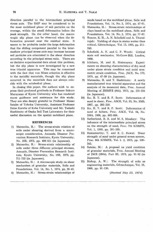
The curves in Fig. 26 illustrate Eq. (29) interms of the relationship between the angle ofinternal friction (b=Cb13=Sin-1 {(i1-r3)/(a1+a3)) andthe parameter b=(Q2-Q3)/(61-63) indicating themagnitude of the intermediate principal stress a3.From this diagram, it is seen that the value of
Fig. 24 Relationship among 01/73, E1 and E3in true triaxial test (RS 45) on looseOttawa sand (after Ko and Scott'sdata).
Fig. 25 Relationship among i1/q3, Ei and E3in triaxial extension test (RS 30) onloose Ottawa sand (after Ko andScott's data).
Fig. 26 Proposed yield condition (failure cri-terion) and measured angles of in-ternal friction of a sand under threedifferent principal stresses (afterSutherland and Mesdary's data).
b=σ2-σ3/σ1-σ3
Stress-Deformation and Strength Characteristics 69
ci is equal with respect to b=0 (triaxial compres-sion condition) and b=1 (triaxial extension con-dition) and asymmetric with respect to b=0.5. The plots given in the diagram represent the re-sults of the test conducted on a certain sand by Sutherland et al.12) Fig. 27 is intended to give, for the purpose of comparison, the results of the test which Ramamurthy et al.13) carried out on a sand. It is seen that the curve given in this diagram bears striking resemblance with that of Eq. (29).
Satake,14) introducing the concept of distance in the stress space, proposes the following yield condition for n=2.
(σ1-σ2/σ1+σ2)2+(σ2-σ3/σ2+σ3)2+(σ3-σ1/σ3+σ1)2
=sin2φ12+sin2φ23+sin2φ31=2k2… … (30)
Eqs. (29) and (30) resemble very much in shape each other, except for the difference between tan b and sin b. Calculation shows that Eq. (29)
gives a slightly larger value of b than Eq. (30), though the difference seems to be limited to within the maximum of 1 where 0<Q<45. It is, therefore, quite difficult to decide from meas-ured values which gives more realistic yield con-dition, Eq. (29) or Eq. (30). In such a case as this, the consistency of the theory may be ques-tioned.
Eishop15) has proposed the following modified equation:
sin= 1-K2b(1-b)
According to this equation, sin il is symmetric with respect to b=0. 5 and, therefore, has a fairly different inclination from Eqs. (29) and (30) de-scribed above. In this equation, Kl and K2 are coefficients which should be determined through
experiments.
6. CONCLUSIONS
In the present paper, the authors first proposed a theory that a new stress plane called "spatial mobilized plane" exists within the three-dimen-sional stress space as a resultant stress plane of the formerly proposed three mobilized planes among the three principal stress axes. They have learnt that the stress-strain relationships of soil under three different principal stresses can be uniquely expressed by analyzing the relationships with respect to this plane. They have derived the equations indicating the principal stress-prin-cipal strain relationship in accordance with this unique stress-strain relationship and verified these equations by use of various test data. They have further proposed a new yield condition of soil on the assumption that soil yields when the shear-normal stress ratio on this plane has reached a fixed value. They have demonstrated that this
yield condition provides a plausible explanation of the test data.
What the authors wish to stress most in this paper is the fact that the spatial mobilized plane proposed herein forms a stress plane which pro-vides a unique interpretation of the stress-strain characteristics to the yield condition (failure cri-terion) of soil under three different principal stresses. For the solution of problems concern-ing deformation and strength of soil, the spatial mobilized plane proves to have an extremely in-teresting nature. As described briefly in Section 4, such interesting nature may not be expected from the octahedral plane which is frequently resorted to today. This distinction is believed to issue from the physical significance of the mobilized plane, i. e., the plane on which soil
particles slide, and the true character of soil as a material fundamentally governed by the fric-tional law. The authors will aim at analyzing the general stress-strain relationships in tensorial expression through this unique stress-strain char-acteristics on the spatial mobilized plane.
A description will be made here with respect to the relationship between the spatial mobilized
plane (SMP) and the slip plane observed in the soil sample. Since soil is an assemblage of par-ticles, soil particles are considered to slide on the each tangential plane at their contact points along the direction of the resultant shear stress when the resultant shear-normal stress ratio on the tangential plane has reached a fixed value. There-fore, they will not necessarily slide only in the
Fig. 27 Measured angles of internal friction of a sand under three different prin-
cipal stresses (after Ramamurthy and Rawat).
70 H. MATSUOKA and T. NAKAI
direction parallel to the intermediate principal stress axis. The SMP may be considered to be the most mobilized plane of soil particles on the average, within the small deformation before the peak strength. On the other hand, the macro-scopic slip plane can be observed when the de-formation proceed near the residual state. It seems to be probable under the large deformation that the sliding component parallel to the inter-mediate principal stress axis may increase because soil particles are orientated to the shear direction according to the principal stress ratio. There are no decisive experimental data about this problem, but the slip plane is now investigated by a new true triaxial apparatus. This may be concerned with the fact that von Mises criterion is effective to the metallic materials, though the slip plane occurred in the materials does not always coin-cide with the octahedral plane.
In closing this paper, the authors wish to ex-
press their profound gratitude to Professor Sakuro Murayama of Kyoto University who has rendered warm guidance and assistance for this study. They are also deeply grateful to Professor Masao Satake of Tohoku University, Assistant Professor Daizo Karube of Kobe University and Mr. Tadashi Hashimoto of Osaka Soil Test Laboratory for their useful discussion on the spatial mobilized plane.
REFERENCES
1) Matsuoka, H. : The stress-strain relation ofsoils under shearing derived from a micro-scopic consideration, Annuals, Disaster Pre-vention Research Institute, Kyoto University,No. 15B, 1972, pp. 499-511 (in Japanese).
2) Matsuoka, H. : Stress-strain relationship ofsoils under three different principal stresses,Annuals, Disaster Prevention Research Insti-tute, Kyoto University, No. 16B, 1973, pp.711-733 (in Japanese).
3) Matsuoka, H. : A microscopic study on shearmechanism of granular materials, Soils andFoundations, Vol. 14, No. 1, 1974, pp. 29-43.
4) Matsuoka, H. : Stress-strain relationships of
sands based on the mobilized plane, Soils andFoundations, Vol. 14, No. 2, 1974, pp. 47-61.
5) Matsuoka, H. : Stress-strain relationships ofclays based on the mobilized plane, Soils andFoundations, Vol. 14, No. 2, 1974, pp. 77-87.
6) Roscoe, K. H., A. N. Schofield and A. Thurai-rajah : Yielding of clays in states wetter thancritical, Geotechnique, Vol. 13, 1963, pp. 211-240.
7) Schofield, A. N. and C. P. Wroth : Criticalstate soil mechanics, McGraw-Hill, London,
1968.8) Ichihara, M. and H. Matsuzawa : Experi-
ments on shearing characteristics of dry sandunder plane strain condition and axial sym-metric strain condition, Proc. JSCE, No. 173,1970, pp. 47-59 (in Japanese).
9) Matsuoka, H. and T. Hashimoto : A newlymanufactured true triaxial apparatus and theanalysis of its measured data, Proc. AnnualMeeting of JSSMFE (8th), 1973, pp. 231-234(in Japanese).
10) Ko, H. Y. and R. F. Scott : Deformation ofsand in shear, Proc. ASCE, Vol. 93, No. SM5,1967, pp. 283-310.
11) Ko, H. Y. and R. F. Scott: Deformation ofsand at failure, Proc. ASCE, Vol. 94, No.SM4, 1968, pp. 883-898.
12) Sutherland, H. B. and M. S. Mesdary : Theinfluence of the intermediate principal stresson the strength of sand, Proc. 7th ICSMFE,Vol. 1, 1969, pp. 391-399.
13) Ramamurthy, T. and R. C. Rawat : Shearstrength of sand under general stress system,Proc. 8th ICSMFE, Vol. 1. 2, 1973, pp. 339-
342.14) Satake, M. : A proposal on yield condition
of granular materials, Proc. Annual Meetingof JSCE (28th), Part III, 1973, pp. 91-92 (inJapanese).
15) Bishop, A. W. : The strength of soils asengineering materials, Gdotechnique, Vol. 16,1966, pp. 91-130.
(Received May 23, 1974)