Stress Concentration Around Inclined Holes in Pressurized Thick ...
27
(D .LEVE ___ uTECHNICAL REPORT ARLCB-TR-78019 Q 0 STRESS CONCENTRATION AROUND INCLINED HOLES IN oPRESSURIZED THICK-WALLED CYLINDERS Y. F. Cheng November 1978 -- ' US ARMY ARMAMENT RESEARCH AND DEVELOPMENT COMMAND ~LARGE CALIBER WEAPON SYSTEMS LABORATORY r ~BENdT WEAPONS LABORATORY ~WATERVLIET, N. Y. 12189 ANCMS No. 6111019A0011 C-, Pron No. 1A-8-25567-GG-M7 JAN 19 APPROVED FOR PUBLIC RELEASE; DISTRIBUTION UNLIMITED ' 19-
-
Upload
truongtruc -
Category
Documents
-
view
223 -
download
1
Transcript of Stress Concentration Around Inclined Holes in Pressurized Thick ...

(D .LEVE ___uTECHNICAL REPORT ARLCB-TR-78019
Q0 STRESS CONCENTRATION AROUND INCLINED HOLES IN
oPRESSURIZED THICK-WALLED CYLINDERS
Y. F. Cheng
November 1978
-- ' US ARMY ARMAMENT RESEARCH AND DEVELOPMENT COMMAND~LARGE CALIBER WEAPON SYSTEMS LABORATORY
r ~BENdT WEAPONS LABORATORY
~WATERVLIET, N. Y. 12189
ANCMS No. 6111019A0011C-, Pron No. 1A-8-25567-GG-M7 JAN 19
APPROVED FOR PUBLIC RELEASE; DISTRIBUTION UNLIMITED
' 19-
DISCLAIMER
The findings in this report are not to be construed as an official
Department of the Army position unless so designated by other author-
ized documents.
The use of trade name(s) and/or manufacturer(s) does not consti-
tute an official indorsement or approval.
DISPOSITION
Destroy this report when it is no longer needed. Do not return it
to the originator.
k.

SECURITY CLASSIFICATION OF THIS PAGE When note N'rrfred)
READ rNSTRUC'F.,REPORT DOCUMENTATION PAGE L EFORF INI TI"N-;, I
" REPORT NU {,_ . 2. GOVT ACCESSION NO. 3 RECIPtENI", < Al r'A U N )%', -I
JARLCB-TR-78019 ____
" TTLE (5bt " - -
) " TyPLOA R • P"It943 ,,l...
JTRESS CONCENTRATION AROUND INCLINED HOLES T i, fN PRESSURIZED THICK-WALLED CYLINDERS O '___ -f
7. AUTHOR(.) 8. CDNTRACT OR GRANT NjM~l f
I. Y.F.j Cheng /
9 PERFORMING ORGANIZATION NAME AND ADOS 1O. PROGRAM El i MENT P'l, " - -
Benet Weapons Laboratory/ AREA t WORK UNIT N,)MUE
Watervliet Arsenal, Watervliet, N.Y. 12189 AMCMS No. 6111O1l9AU.1'DRDAR-LCB-TL PRON No. lA-8-25567-L(G-,
II CONTROLLING OFFICE NAME AND ADDRESS ),.0 LO. - - - - -.... ..-
US Army Armament Research and Development Command NovLarge Caliber Weapon Systems Laboratory .. .lover, New Jersey 07801 24
14 MONITORING AGENCY NAME & ADDRESS(if different from Controlling Office) 1%. SECURITY CLASS. (of 'hi. r.p,r
Ia DECLASSIFCATION DOWNGRA L""SCHEDULE
16 DISTRIBUTION STATEMENT (of this Report)
Approved for public release; distribution unlimited.
I7. DIST J(o . *bIrscE (of hs lered In Block 20, It different from Report)
I8. SUPPLEMENTARY NOTES
19. KEY WORDS (Contnue on reve.re side It necessary a. d Identify by blocc nuber) U U nm UZb) L ' -i-
Hole -"Pressurized CylindersStress ConcentrationThick-Walled Cylinders
20. A STRACT ('tCatftflue a srtie ro ff nrc"*... and identlfy by block number)
Photoelastic investigation has been conducted to study stress cercertrd-tion around inclined holes in pressurized thick-walled cylinders. it !>, ,found that an inclination in the transverse plane reduces the stress L, cL-tration and an inclination in the meridianal plane increases the strels coLL -tration. Also, the stress concentration depends upon the bore-to-hole di.c;tCrratio among other parameters.
DO R 1473"EDITIoNOF I NOV SS IS OBSOLETE
SECURITY C4ASSIFICATION Or THIS PAGF

ACKNOWLEDGEMENT
Charles Cobb's participation in the experimental phase of this
investigation is hereby acknowledged.
WWUION for
gUAURPED DiISTICATIO$
TABLE OF CONTENTS
Page
AC KNOWLEDGEMENT i
NOMENCLATURE iv
INTRODUCTION 1
LITERATURE SURVEY 1
EXPERIMENTS AND RESULTS 5
Models 5
Slicing 7
Shape of Hole on the Inside Wall as Seen Along the
R-Direction 7
A. Holes in the RO-Plane, f = 0 7
B. Holes in the RZ-Plane, a = 0 9
Photoelastic Observation 9
Experimental Results 11
CONCLUSIONS 16
SUGGESTIONS 16
REFERENCES 17
ILLUSTRATIONS
1. Projection of holes, a $ 0, = 0. 8
2. Shape of holes on the inside wall as seen along theR-direction. 10
3. Position of maximum fringe intensity. 12
4(a). K versus a at constant values of R1/rl, 0 = . 13
4(b). K versus B; a 0 0, R1/r1 = 5. 14
ii
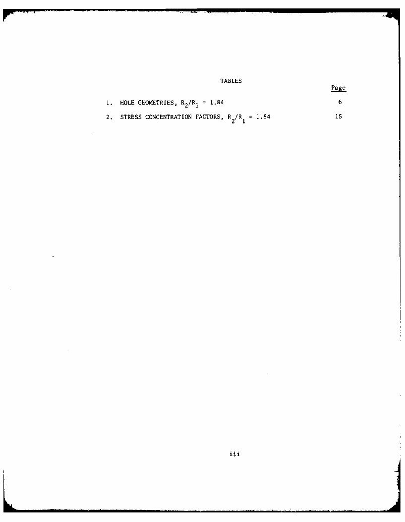
TABLES
Page
1. HOLE GEOMETRIES, R 2/Rj = 1.84 6
2. STRESS CONCENTRATION FATR, R 2/R = 1.84 15

NOMENCLATURE
R,e,Z Cylindrical coordinate system, Z coincides with the axis
of the cylinder.
r,$,z Cylindrical coordinate system, z coincides with the axis
of the hole.
RI,R, Inside and outside radius of the cylinder, respectively.
rI Radius of the hole.
OrO¢,o@e Normal stress along the rA,e direction, respectively.
p Pressure.
K Stress concentration factor.
c Ellipticity, i.e., the ratio of the major/minor axis of an
ellipse.
Angle of inclination in the RO-plane.
Angle of inclination in the RZ-plane.
X,Y;x,y Rectangular coordinate systems.
N Fringe intensity; i.e., fringe per unit thickness.
f Material fringe value.
iv
INTRODUCTION
The service life or load carrying capacity of pressurized cylinders
with holes is dependent upon stress concentrations at the holes. As a
result, a knowledge of the stresses at the bore-hole interface is
important because many thick-walled cylinders contain holes for
lubrication, valves, and other purposes. In high pressure applications,
the state of stress in a cylinder with holes is needed because fatigue
life is very critical and present day weight limitation prevents high
factors of safety. The purpose of our investigation concerns itself
with the stress concentration at evacuator holes in gun tubes.
Evacuator holes are small holes inclined to the tube axis. This
investigation includes holes in the transverse (RO) plane as well as
those in the meridianal (RZ) plane. The effects of bore-to-hole-
diameter ratio and the angle of inclination on stress concentration
were determined. The results are given and future work is suggested
LITERATURE SURVEY
A survey of the literature shows that in 1956, Fessler and Lewin
determined the stress distribution in a tee-junction of thick pipes
subjected to internal pressure. Analytically, they treated cylindrical
laminae of the main pipe as infinite flat plates, each with a circular
hole, under the action of two perpendicular tensions and an internal
1H. Fessler and B. H. Lewin, "Stress Distribution in a Tee-Junction ofThick Pipes," British Journal of Applied Physics, Vol. 7, pp. 76-79,February 1956.
1

pressure p acting in the hole. The perpendicular tensions are the
theoretical hoop (Lame) and axial stresses which would act on the
)articular laminae of the main pipe if the branch did not exist. They
obtained approximate solutions for stresses 7 and (r when the ratio
r /R is small, as follows:
R22 R12 p 1 2 r 2 cos 3r I
0 2 12 Y + +oT2¢ +1 + + )]1(2 (R2
2 -R 1
R22R2 Ir - cos2 4r, 2 3rl' )
r 12 + " ) (1 + _--
r 2(R 2 - R12 ) R2 R 2 r
2 R2 R12 R2 r2 r4
(2)
The stress o¢ has a maximum value at the junction where R Rl, r r,
and ¢ = 0. Thus4R2
2 + R12
G4max (3)R22 - R,
and the stress concentration factor (ratio of U¢ max to the Lame hoop
stress without the hole)R2 2+R1
2 4R 2 +R1 2
=(max' 22 2)P] R22 R1
2
R2 2-R1 2 R
They also performed a three-dimensional photoelastic experiment using
a model with R, = 3R1 and R, = 2r 1 . A value 'r ( 0 ,max = 3.50 p and
K = 2.80 were obtained experimentally in comparison with the calculated
value of (Y ,max = 4.62 p and K = 3.70. The calculated K is 32%
greater than the experimental value, probably indicating that R1 = 2r1
is too large for equation (1) to be applicable.
2

4.
In 1965, Little 2 , Little and Bagci showed that stress concentration
has a higher value
4R22+2R1
2
R2 2=5)R2 ,RI2
in open-end cylinders under internal pressure. They also showed stress
concentrations for small inclined holes in the transverse (RO) plane
as well as those in the meridianal (RZ) plane. In the former case, the
holes are not radial except for those having a zero angle of inclination.
The contour of the hole on the bore of the cylinder, when the angle of
inclination is small, was approximately represented by an ellipse with
major axis perpendicular to the Z-direction. Stress concentration occurs
at the ends of both major and minor axes. At the ends of the major axis,
they have a value of
2(c-l)R 22+R1
2 (6)R2
2+R12
for closed-end cylinders, and2(c-1)R 2
2-2cR12
K= (7)R2+R1 2
for open-end cylinders. At the ends of minor axis, they have a value of
K = (4R2 2/c)+R 12 (8)
R2 2+R2
2R. E. Little, "Stress Concentrations for Holes in Cylinders," MachineDesign, Dec. 23, 1965, pp. 133-135.
3R. E. Little and C. Bagci, "Stress Analyses of Pressurized Cylinders,"Engineering Research Bulletin, Publication No. 145, Oklahoma StateUniversity, March 1965.
3

for closed-end cylinders, and
K- - (90.2 +r? 1 2
for open-end cylinders. In the latter case, the hole becomes anellipse %ith its major axis parallel to the Z-direction. Stress
coucciitration occurs at the ends of te ,j]or a Th J.y have a va I Lie
of4cR9
2 +RK" - (ICr'
p 2 + .22 1
for closed-end cylinders, and4cR2 2 +2R12
2 2R2+R1l
for open-end cylinders. No experimental wrh has Leer. shown. Thc y
pointed out that inclinations in the RZ plane should be avoided since
K would be very large from equations (10) and (11) vith a high value of
C.
In 1968,0'llara 4 reported a photoelastic investigatien on stress
concentration factors on holes inclined in the transverse (R'') plane.
In a closed-end cylinder of R2 = 1.75R 1, O'Hara reported an experimental
value of K of 2.75, 2.95 and 2.46 for radial holes (:ero inclination)
of 2Or1, 10ri, and 5rI, respectively, i. comy:rison xith
calculated value of 3.26 from Eq. (4). The calculated stress conccn-
tration factor is 14% greater than the average experimental value
4 C. P. O'Hara, "Experimental Investigation of Stress ConcentrationFactors of Holes in Thick Walled Cylinders," Watervliet ArsenalTechnical Report WVT-6807, June 1968.
,[, 4
(neglecting the result from Rl = 5rl). His data on inclined holes
were not informative since his photoelastic observation was made along
the axis of the hole (z-direction) and G was not determined.
In 1972, Gerdeen 5'6 published analytical and experimental results,
and concluded that the optimum configuration of a thicl-walled
cylinder with a radial hole in the transverse plane is one with equal
bore and hole diameters.
In summary, published results show that calculated stress
concentration factors at radial holes are higher than those obtaincd
experimentally. No experimental work on inclined holes is available.
EXPERIMENTS AND RESULTS
Models. Three cylinders having an inside diameter of 3 1/8 in.
and outside diameter of 5 3/4 in. were machined from epoxy resin reds
supplied by PHOTOLASTIC under trade name PLM4B. They were closed on
both ends with caps containing holes for pressure inlet and manometer
connections. Twenty-four holes with three radii, four angles of
inclination a, in the RO-plane, and four angles of inclination, P, in
the RZ-plane were distributed among these cylinders, as shown in Table
1. The angular and axial separations between holes were sufficient
such that no interaction of stresses between holes were observed. 'TIhese
holes were sealed at the outside wall of the cylinder. These cylinders
5J. C. Gerdeen, "Analysis of Stress Concentrations in Thick CylindersWith Sideholes and Crossholes," Journal of Engineering for Industry,Vol. 94, No. 3, pp. 815-824, Aug 1972.J. C. Gerdeen and R. E. Smith, "Experimental Determination of Stress-
Concentration Factors in Thick-Walled Cylinders with Crossholes andSideholes," EXPERIMENTAL MECHANICS, Vol. 12, No. 11, pp. 530-536,Nov 1972.
S
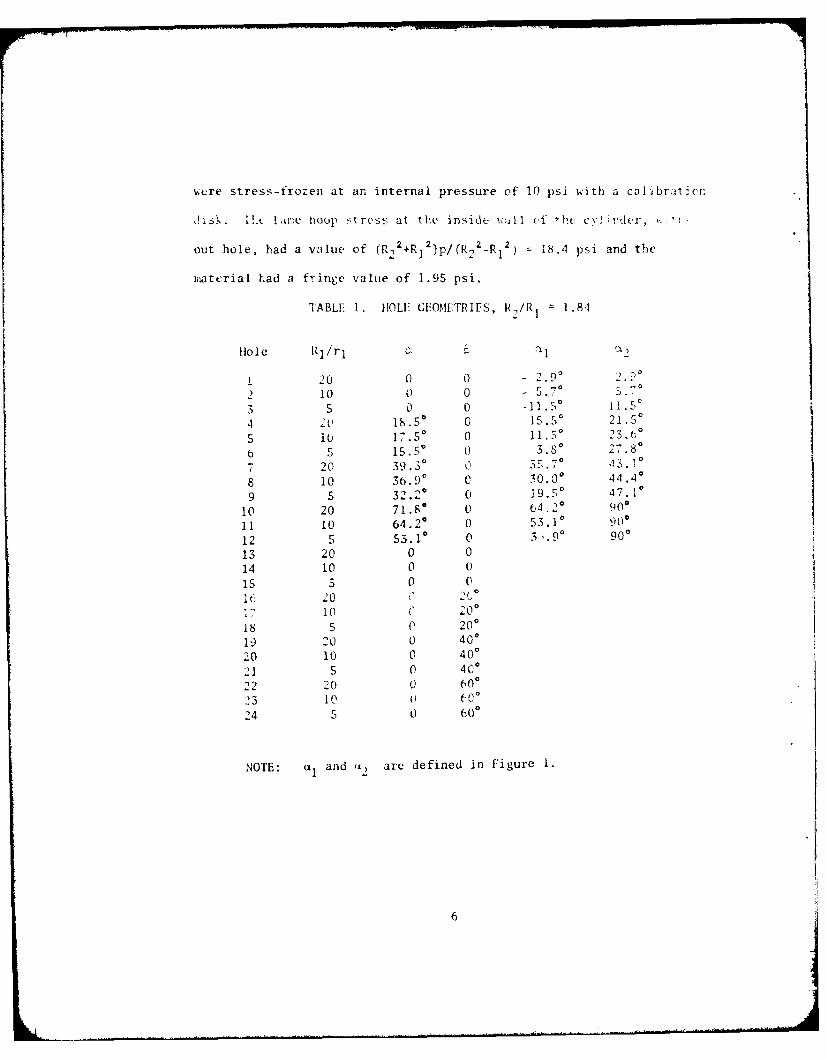
wcre stress-frozen at an internal pressure of 10 psi with a calibrat;cr
ii s . L!.c Lair.e houp stress at the inside ,' (,f ti ci v iV ,ter, ,.., -
out hole, had a value of (R 22 +R)P/(R 2 I-R1
2 ) = 18.4 psi and the
material had a fringe value of 1.95 psi.
TABLE 1. IOLE GEOMFTRIES, R/R 1 = 1.84
Hole Rj/r 1 C1
1 20 0 0 - 2.90 2. °
0
2 10 0 0 - 5.70 3.
3 5 0 0 -15 15
4 20 18.S 0 15.5" 21.50
5 10 17.50 0 11.3o 23.(o
6 5 1S.S 3.8 0 27.80
7 20 39.30 -3. °
8 10 36.90 C 30.0 44.4
9 5 32.20 0 19.50 47.10
10 20 71.8 0 64 20 900
11 10 64.2 ° 0 53.10 90
12 5 53.1 0 3.9 ° 900
13 20 0 0
14 10 0 0
15 5 0 0i B 20 ' 25
i7 10 0 20o
18 5 0 200
19 20 0 400
20 10 0 40o
21 5 0 40o
22 20 0 60023 10 60
24 5 0 600
NOTE: and u2 are defined in Figure 1.
.... ....6

Slicing. Stress concentration factor K was computed as the ratio
of the m:.Imum value of o to the Lame hoop stress without the hole.
It is known that o€ attains its maximum at the inside wall of the
cylinder. Hence, wall thickness of the cylinders was reduced to
0.10 in by removing materials from the outside wall and leaving
materials at the inside wall untouched. After thickness reduction,
these cylinders were cut into twelve sections, each containing two
holes with an angular separation of about 180 degrees.
Shape of Hole on the Inside Wall as Seen Along the R-Direction
A. Holes in the RO-Plane, 0. Let the bore of the cylinder
be represented by
X2 + y2 = R 2 (12)
and the hole by
x2 + y2 = r12 (13)
The direction of observation, R-direction, is defined by a, the angle
of inclination, Figure 1, and is normal to the tangential plane T
containing the point of tangency D having its coordinates Rlsina and
Rlcosa. The projection of the contour PDQDP of the hole on a plane S
parallel with the tangential plane T gives the shape of the hole as
seen radially. Let A, defined simultaneously by coordinates (X,Y) and
(x,y) be a point on the contour and A'(x',y') be the projection of A
on the S-plane. From geometric consideration, Figure 1, we have
= [(Rlsina*rl)-X]2 + {Y-[R,2-(Rlsint+r1 )2]1/2 }2 (14)
and
7

0II
0'
(I)
0
K'U
~73Z77~ ~,/ -J~,LLd4 ~
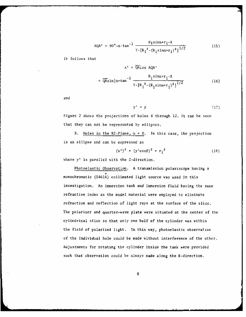
AQA' = 900-a-tan- RlsinoL+rl-Xy_[R1 2 -(RlsinoL+rl) 2]l/2 (S
It follows that
x'= QAcos AQA'
= TAsin[ot+tan -1 R 1sina+rl-X (16)Y-[R 2 - (Rlsin+ri)2
] 1/21
and
y =y (17)
Figure 2 shows the projections of holes 4 through 12. It can be seen
that they can not be represented by ellipses.
B. Holes in the RZ-Plane, a = 0. In this case, the projection
is an ellipse and can be expressed as
(X,) 2 + (y'cos )2 = r12 (18)
where y' is parallel with the Z-direction.
Photoelastic Observation. A transmission polariscope having a0
monochromatic (5461A) collimated light source was used in this
investigation. An immersion tank and immersion fluid having the same
refractive index as the model material were employed to eliminate
refraction and reflection of light rays at the surface of the slice.
The polarizer and quarter-wave plate were situated at the center of the
cylindrical slice so that only one half of the cylinder was within
the field of polarized light. In this way, photoelastic observation
of the individual hole could be made without interference of the other.
Adjustments for rotating the cylinder inside the tank were provided
such that observation could be always made along the R-direction.
9

SZ
10

One observation at a = 0 was made for holes 1 to 3 and 13 to 24. For
holes 4 to 12, three observations were made, one each at a, al, and a2,
Figure 1 and Table 1. Photographs of isochromatic fringes were taken
from each observation, and fringe intensity, N, was calculated.
Experimental Results. From the linear relationship between fringe
order and the principal stress difference, we have, at the hole
Nf = o6-p (19)
and
c0 = Nf+p (20)
For holes I to 3 and 13 to 15, maximum value of N was found at point
M, Figure 3, where ae is equivalent to o¢. For holes 4 to 12,
maximum value of N was also found at M, not at L nor R. Thus
=,max = Nmaxf+P (21)
and
K = GO,max/18.4 (22)
The stress concentration factors, photoelastically determined as well
as calculated from Eqs. (4), (8), and (10), are shown in Table 2.
Data from holes 10, 11, 12, 16, 17, 19 and 22 were lost due to
material breakage during slice preparation. Figure 4 shows curves of
K versus a and a at constant values of R1 /r1 . These results show that (a)
for a = 0, K decreases as R1 /r1 decreases; (b) for 6 = 0 and a
constant R1/rl, K decreases as a increases, and (c) for a = 0, K
increases as R increases. It also shows that calculated values
are too high. Moreover, it can be seen that an inclination in the RE-
plane reduces the stress concentration. However, an inclination in the
RZ-plane raises the stress concentration.
11j

M
Hole / i 3. /3to 15
Hole16 z
Hole- /6 24
F, L're 3. P.. os/-1O of rnax 7a/m
1

r -
I
C.
0
________ ____ V)
NN 0
if
0ft.,
~0
N
0
0
N 0
13

0 0 40 60 8
3,degrees
Fl'q 4-(b). KCversus 13; :w, , ql/r5
14
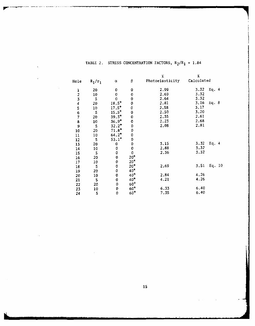
TABLE 2. STRESS CONCENTRATION FACTORS, R2/R1 = 1.84
K K
Hole R1/rI a Photoelasticity Calculated
1 20 0 0 2.99 3.32 Eq. 4
2 10 0 0 2.69 3.32
3 5 0 0 2.64 3.32
4 20 18.50 0 2.81 3.16 Eq. 8
5 10 17.5' 0 2.58 3.17
6 5 15.50 0 2.50 3.20
7 20 39.30 0 2.35 2.61
8 10 36.90 0 2.23 2.68
9 S 32.2* 0 2.08 2.81
10 20 71.8* 011 10 64.2* 0
12 5 53.10 013 20 0 0 3.15 3.32 Eq. 4
14 10 0 0 2.88 3.32
15 5 0 0 2.36 3.32
16 20 0 20017 10 0 20*
18 5 0 200 2.69 3.51 Eq. 10
19 20 0 40020 10 0 40' 2.84 4.26
21 5 0 40' 4.21 4.26
22 20 0 600
23 10 0 60* 6.33 6.40
24 5 0 600 7.35 6.40
15

Co\C bUS IONS
I. It has been shown that the shape of the hole inclined in the
R(;-plaow, as seen radial lv, do es not appe;ar ,: ar el ilpe. Hence,
Lquation (8) is not applicable.
2. Although the shape of the hole inclined in the RZ-plane, as
cFen radially, appears as arl ellipse, equation (10) considers only an
elliptical through-the-wall hole instead of an inclined hole.
3. From the results of holes 1 to 3 and 13 to 15, it shos tl'.,t
equation 4 is limited to a high value of R]/r 1.
4. All three analytical equations (4, 8, 10) have not taken tl,e
-ize of the hole into account. Experi.mental results show that stress
c-ocentration factors depend on the bore-to-hole ratio, i.e., the izc
ot the hole, and other parameters.
S. Stress concentration factors are reduced by inclining in the
I -plane and are raised by inclining in the RZ-plane. Hence, an
inclination in the RZ-plane should be avoided.
SUGGESTIONS
Evacuator holes in gun tubes are small holes inclined to the tube
axis. It has been found from present investigations that this type of
inclination increases the stress concentration. It might be beneficial
to investigate the effect of superposing an inclination in the RO-plane
with that in the RZ-plane. ;t is hoped that the reduction of h from
an inclination in the RO-plane 01 partially compensate the increasing
of K from an inclination in the RZ-plane. Also, it might be useful to
coaduct experiments under open-end conditions.
16

REFERENCES
1. H. Fessler and B. H. Lewin, "Stress Distribution in a Tee-Junction
of Thick Pipes," British Journal of Applied Physics, Vol. 7,
pp. 76-79, February 1956.
2. R. E. Little, "Stress Concentrations for Holes in Cylinders,"
Machine Design, Dec. 23, 1965, pp. 133-135.
3. R. E. Little and C. Bagci, "Stress Analyses of Pressurized
Cylinders," Engineering Research Bulletin, Publication No. 145,
Oklahoma State University, March 1965.
4. G. P. O'Hara, "Experimental Investigation of Stress Concentration
Factors of Holes in Thick Walled Cylinders," Watervliet Arsenal
Technical Report WVT-6807, June 1968.
5. J. C. Gerdeen, "Analysis of Stress Concentrations in Thick
Cylinders With Sideholes and Crossholes," Journal of Engineering
for Industry, Vol. 94, No. 3, pp. 815-824, Aug 1972.
6. J. C. Gerdeen and R. E. Smith, "Experimental Determination of Stress-
Concentration Factors in Thick-Walled Cylinders with Crossholes and
Sideholes," EXPERIMENTAL MECHANICS, Vol. 12, No. 11, pp. 530-536,
Nov 1972.
17
WATIRVlI IET ARSENAL INTERNAL DISTRIBUTION LIST
NO. OFCOP-I E S
I) Ikl:CIOR, BENE'T WFAP(jNS LABORATORY 1
('IE{ [:F, { i:;':LOl,f, M NT I LGEIXi-RING BRANCH 1AITN: i R!'I)AR- LCBI)A 1
-DM 1-DP I-DR 1-DS 1-DC 1
CHIEF, ENGINEERING SUPPORT BRANCH 1
CHIEF, RESEARCH BRANCH 2ATTN: DRDAR- LCB-RA 1
-RC I-RM 1-RP 1
TECHNICAL LIBRARY 5
TECHNICAL PUBLICATIONS EDITING UNIT 2
DIRECTOR, OPERATIONS DIRECTORATE 1
DIRECTOR, PROCUREMENT DIRECTORATE 1
DIRECTOR, PRODUCT ASSURANCE DIRECTORATE 1
NOTE: PLEASE NOTIFY DIRECTOR, BENET WEAPONS LABORATORY, ATTN:
DRDAR-LCB-TL, OF ANY REQUIRED CHANGES.

XIlRN'qAL DISTRIBUTION LIST (CONT)
NO. OF NO. OFCOP I ES (OP I ES
. !','>{. ",'w COM',1AND)ER
A1 ", Y IFAR;Il }FICE DEFENSE DOCU CENP.O. BMX 12211 1 ATTN: DDC-TCA 12
,, , . , K, NC 27709 CAIIERON STATIONALEXANDRIA, VA 22314
qAY ,IY A.;R'Y ih ;D LAB METALS & CERAMICS INFO CENAl 'N: "LO LIB 1 BATTELLE COLUMBUS LAB
O8100 P NIl L ROAD SOS KING AVEAOLE'i lFMA, MD 20783 COLUMBUS, OHIO 43201
'i RECTOR 1PDCUS AP}IY jNITlij'RIAL BASE ENG ACT 13919 W. BAY SHORE DR.
ATTN: DRX PE-I 1 TRAVERSE CITY, MI 49684ROCK SLA'ND, IL ')1201
CHIEF, MAIETIAILS RANCHUS Ai,:.IY RI S GiP)lJP, EUR 1BOX oS, [P0 N.Y. 0O510
C 'c. .. :, LDE R
NAVAL SURFACE ',EiA2ONS CENA'IIrN: CHIEF, MIAT SCIJENCE DIV I.A~il. k.EN, VA 22:4 8
DIRECTORUS NAVAL RESEARCH LABATTN: DI,, MI{CH DIV I
CODE 26-27 (DOC LIB) IWASIiINc;TON, D.C. 20375
.AA SCIFNTIFIC TECH INFO FAC
P.O. BOX 8757, ATTN: ACQ BR 1BALTIMORE/ AStIlNGTON INTL AIRPORTMARYLAND 21240
NOTE: PLEASE NOFIFY COMMANDER, ARRADCOM, ATTN: BENET WEAPONS LABORATORY,DI.IjAR-E.B-'I., tWATERVLIET ARSENAL, WATERVLIET, N.Y. 12189, OF ANYRIAAb IP1:7 (HlANGES.
EXTERNAL DISTRIBUTION LIST
NO. OF NO. OFCOPIES COP I FS
ASSF SEC OF TlE ARMY COMMiANDER[1ISLARClI t DEVELOPMIENT US ARMY TANK-AUTMV R&D COMDAfI'N: Hi.P FOR SCI & TECH 1 ATTN: TECH LIB - DRDTA-UL 1TIlE PENTAGON MAT LAB - DRDTA-RK 1,'ASIUINGTON, D.C. 20315 WARREN, MICHIGAN 48090
(:o '!:.IAN DiE R COM.M IANDERUS ARMY MAT DEV & READ. COMD US MILITARY ACADEMY
ATTN: I)RCDE 1 ATTN: CHMN, MECH ENGR DEPT 1.-,001 EISENHOW'ER AVE WEST POINT, NY 10996
ALEXANDRIA, VA 22333COIMANDER
('O:AN DE R REDSTONE ARSENAL
US ARMY ARRADCOM ATTN: DRSMI-RB 2AT I'N: DRDAR-TSS 2 DRSMI-RRS 1
DRDAR-LCA (PLASTICS TECH 1 DRSMI-RSM 1EVAL CEN) ALABAMA 35809
DOVER, NJ 07801COMMANDER
CO'TL.VNDER ROCK ISLAND ARSENAL
US ARMqY ARRCOM ATTN: SARRI-ENM (MAT SCI DIV) 1
ATTN: DRSAR-LEP-L 1 ROCK ISLAND, IL 61202
ROCK ISLAND ARSENALROCK ISLAND, IL 61299 COMMANDER
HQ, US ARMY AVN SCHDIRECTOR ATTN: OFC OF THE LIBRARIAN 1
US Army Ballistic Research Laboratory FT RUCKER, ALABAMA 36362
ATTN: DRDAR-TSB-S (STINFO) IABERDEEN PROVING GROUND, MD 21005 COMMANDER
US ARMY FGN SCIENCE & TECH CEN
COMMANDER ATTN: DRXST-SD 1US ARMY ELECTRONICS COMD 220 7TH STREET, N.E.ATTN: TECH LIB 1 CHARLOTTESVILLE, VA 22901
FT MONMOUTH, NJ 07703COMMANDER
COMM ANDER US ARMY MATERIALS & MECHANICSUS ARMY MOBILITY EQUIP R&D COMBI RESEARCH CENTERATfN: TECH LIB I ATTN:, TECH LIB - DRXMR-PL 2FT BELVOIR, VA 22060 WATERTOWN, MASS 02172
NOTE: PLEASE NOTIFY COM,?,IANDER, ARRADCOM, ATTN: BENET WEAPONS LABORATORY,
DRDAR-LCB-TL, WATERVLIET ARSENAL, WATERVLIET, N.Y. 12189, OF ANYREQUIRED CHANGES.