STRESS AND DEFORMATION ANALYSIS OF LINEAR ELASTIC...
30
Chapter 12 STRESS AND DEFORMATION ANALYSIS OF LINEAR ELASTIC BARS IN TORSION 12.1 Introduction In Chapter 11, the analysis of long bars subjected only to axial loads was considered. We now consider similar bars but subjected to torsional loads that cause twisting of the bar about its axis. Typical examples include shafts in engines, turbines, torque converters, transmissions, electric motors and similar devices. Figure 12.1: PT6-A Turbine Engine Simple tools like a screwdriver develop a torsional stress and twist of the screwdriver when a screw is driven into wood; likewise a wrench applied to the head of a bolt applies a torque to the bolt which causes twisting of the bolt and internal torsional stresses. When these torsional stresses exceed the shear strength of the material, failure will occur. In addition, the torsional load may induce twisting of the shaft that is excessive. 267
Transcript of STRESS AND DEFORMATION ANALYSIS OF LINEAR ELASTIC...
Chapter 12
STRESS AND DEFORMATIONANALYSIS OF LINEARELASTIC BARS IN TORSION
12.1 Introduction
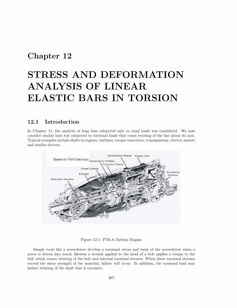
In Chapter 11, the analysis of long bars subjected only to axial loads was considered. We nowconsider similar bars but subjected to torsional loads that cause twisting of the bar about its axis.Typical examples include shafts in engines, turbines, torque converters, transmissions, electric motorsand similar devices.
Figure 12.1: PT6-A Turbine Engine
Simple tools like a screwdriver develop a torsional stress and twist of the screwdriver when ascrew is driven into wood; likewise a wrench applied to the head of a bolt applies a torque to thebolt which causes twisting of the bolt and internal torsional stresses. When these torsional stressesexceed the shear strength of the material, failure will occur. In addition, the torsional load mayinduce twisting of the shaft that is excessive.
267
268CHAPTER 12. STRESS AND DEFORMATION ANALYSIS OF LINEAR ELASTIC BARS IN TORSION
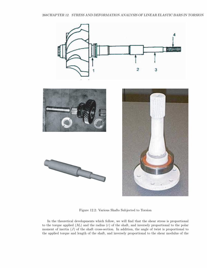
Figure 12.2: Various Shafts Subjected to Torsion
In the theoretical developments which follow, we will find that the shear stress is proportionalto the torque applied (Mt) and the radius (r) of the shaft, and inversely proportional to the polarmoment of inertia (J) of the shaft cross-section. In addition, the angle of twist is proportional tothe applied torque and length of the shaft, and inversely proportional to the shear modulus of the
12.2. THEORETICAL DEVELOPMENT FOR TORSION OF A BAR 269
Figure 12.3:
material (G) and the polar moment of inertia (J). With sufficient knowledge of these parameters, ashaft can easily be designed to prevent material failure and excessive twisting.
12.2 Theoretical Development for Torsion of a Bar
Consider a long, slender bar with a circular cross-section that is subjected to torsion by appliedconcentrated and distributed torques as shown below. The x-axis is placed at the centroid of thecross-section.
500 in-lb 1,000 in-lb
12 in 10 in 7 in 8 in 10 in
100 in-lb/inOD = 3 in
x
y
z
OD = 2.5 in
Figure 12.4: Circular Bar Subjected to Torque Loading
The cross-section may be either a solid circular section or a circular tube. The restriction toa circular cross-section is due to the simplified analysis that will be developed herein. An appliedtorque with a counterclockwise action is considered positive (such as the torque applied at the rightend of the bar in Figure 12.4); and such a torque would have a moment (torque) vector pointed inthe positive x direction when following the usual right-hand rule.
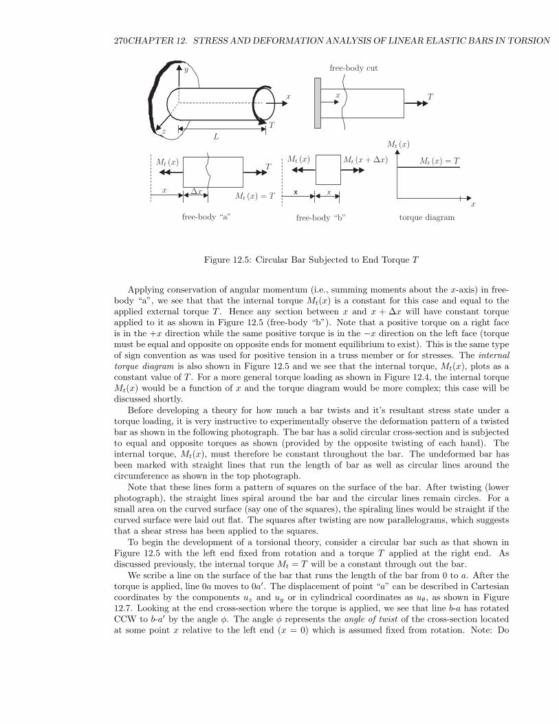
Consider now a section of a bar that has a constant internal torque about the x-axis. An examplemight be a bar that is fixed at its left end and has a torque T applied at its right end as shownbelow. Cut the shaft as some point x and assume the internal torque is Mt(x).
270CHAPTER 12. STRESS AND DEFORMATION ANALYSIS OF LINEAR ELASTIC BARS IN TORSION
x x
x
y
zT
L
free-body cut
Mt (x)
x
∆xMt (x) = T
free-body “a”
Mt (x) Mt (x + ∆x)
free-body “b” torque diagram
T
x
T
x
Mt (x)
Mt (x) = T
Figure 12.5: Circular Bar Subjected to End Torque T
Applying conservation of angular momentum (i.e., summing moments about the x-axis) in free-body “a”, we see that that the internal torque Mt(x) is a constant for this case and equal to theapplied external torque T . Hence any section between x and x + ∆x will have constant torqueapplied to it as shown in Figure 12.5 (free-body “b”). Note that a positive torque on a right faceis in the +x direction while the same positive torque is in the −x direction on the left face (torquemust be equal and opposite on opposite ends for moment equilibrium to exist). This is the same typeof sign convention as was used for positive tension in a truss member or for stresses. The internaltorque diagram is also shown in Figure 12.5 and we see that the internal torque, Mt(x), plots as aconstant value of T . For a more general torque loading as shown in Figure 12.4, the internal torqueMt(x) would be a function of x and the torque diagram would be more complex; this case will bediscussed shortly.
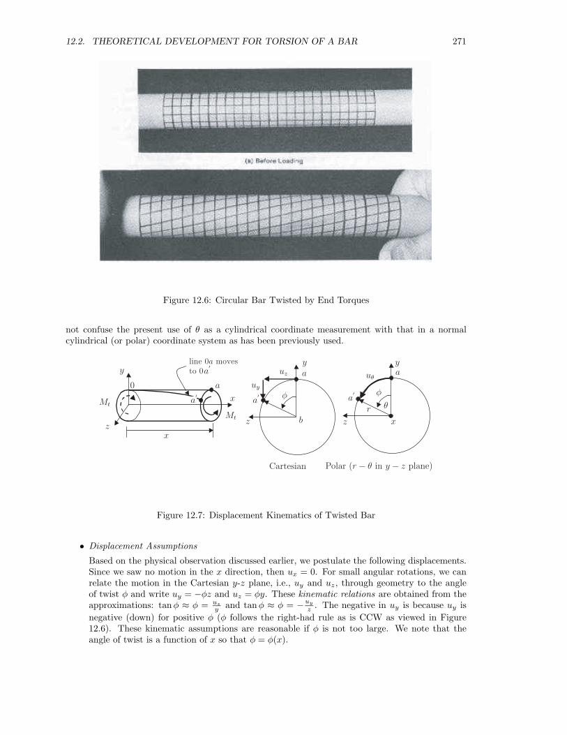
Before developing a theory for how much a bar twists and it’s resultant stress state under atorque loading, it is very instructive to experimentally observe the deformation pattern of a twistedbar as shown in the following photograph. The bar has a solid circular cross-section and is subjectedto equal and opposite torques as shown (provided by the opposite twisting of each hand). Theinternal torque, Mt(x), must therefore be constant throughout the bar. The undeformed bar hasbeen marked with straight lines that run the length of bar as well as circular lines around thecircumference as shown in the top photograph.
Note that these lines form a pattern of squares on the surface of the bar. After twisting (lowerphotograph), the straight lines spiral around the bar and the circular lines remain circles. For asmall area on the curved surface (say one of the squares), the spiraling lines would be straight if thecurved surface were laid out flat. The squares after twisting are now parallelograms, which suggeststhat a shear stress has been applied to the squares.
To begin the development of a torsional theory, consider a circular bar such as that shown inFigure 12.5 with the left end fixed from rotation and a torque T applied at the right end. Asdiscussed previously, the internal torque Mt = T will be a constant through out the bar.
We scribe a line on the surface of the bar that runs the length of the bar from 0 to a. After thetorque is applied, line 0a moves to 0a′. The displacement of point “a” can be described in Cartesiancoordinates by the components uz and uy or in cylindrical coordinates as uθ, as shown in Figure12.7. Looking at the end cross-section where the torque is applied, we see that line b-a has rotatedCCW to b-a′ by the angle φ. The angle φ represents the angle of twist of the cross-section locatedat some point x relative to the left end (x = 0) which is assumed fixed from rotation. Note: Do
12.2. THEORETICAL DEVELOPMENT FOR TORSION OF A BAR 271
Figure 12.6: Circular Bar Twisted by End Torques
not confuse the present use of θ as a cylindrical coordinate measurement with that in a normalcylindrical (or polar) coordinate system as has been previously used.
x
y
zx
Mt
0
a
a′
uz
uy
b
φθr
uθ
Cartesian Polar (r − θ in y − z plane)
Mt
a
a′
y
z
ya
z
φ
x
line 0a movesto 0a
′
a′
Figure 12.7: Displacement Kinematics of Twisted Bar
• Displacement Assumptions
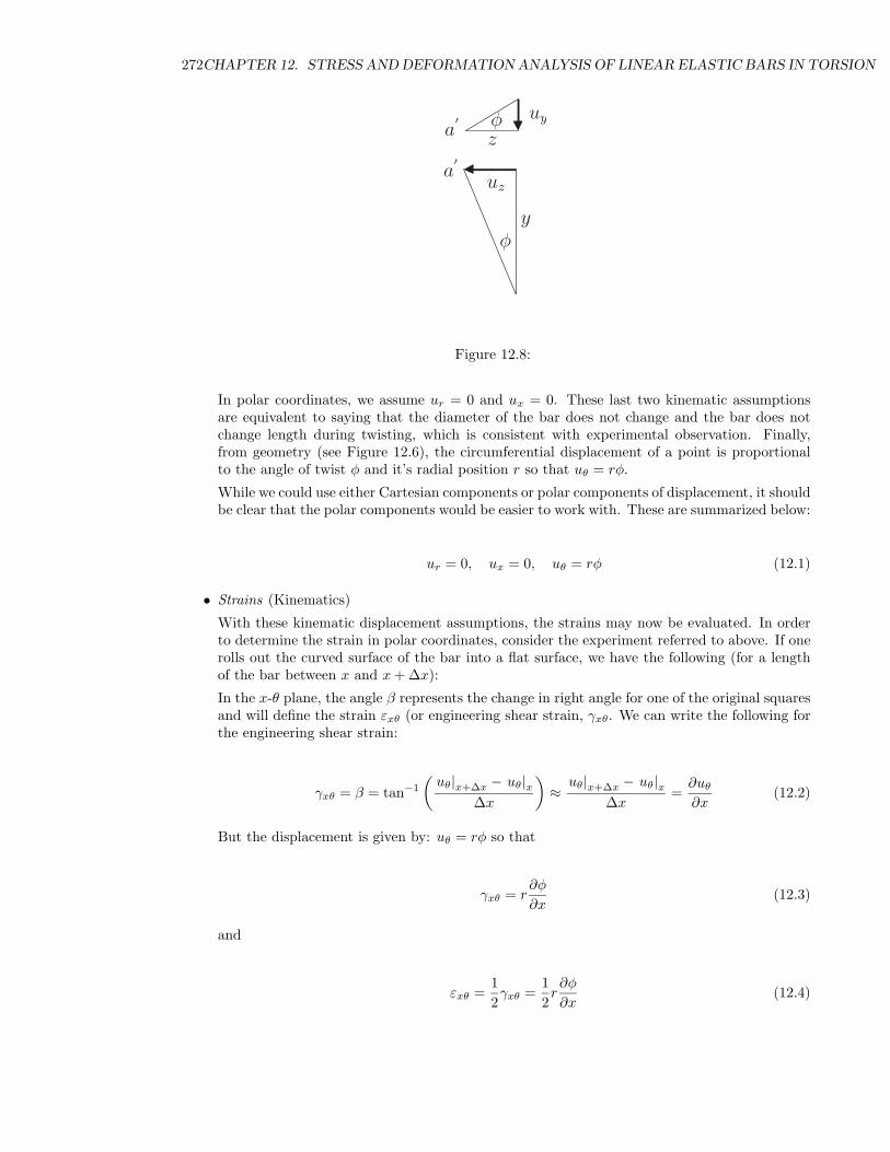
Based on the physical observation discussed earlier, we postulate the following displacements.Since we saw no motion in the x direction, then ux = 0. For small angular rotations, we canrelate the motion in the Cartesian y-z plane, i.e., uy and uz, through geometry to the angleof twist φ and write uy = −φz and uz = φy. These kinematic relations are obtained from theapproximations: tanφ ≈ φ = uz
y and tanφ ≈ φ = −uy
z . The negative in uy is because uy isnegative (down) for positive φ (φ follows the right-had rule as is CCW as viewed in Figure12.6). These kinematic assumptions are reasonable if φ is not too large. We note that theangle of twist is a function of x so that φ = φ(x).
272CHAPTER 12. STRESS AND DEFORMATION ANALYSIS OF LINEAR ELASTIC BARS IN TORSION
y
z
a′
uz
uy
φ
a′ φ
Figure 12.8:
In polar coordinates, we assume ur = 0 and ux = 0. These last two kinematic assumptionsare equivalent to saying that the diameter of the bar does not change and the bar does notchange length during twisting, which is consistent with experimental observation. Finally,from geometry (see Figure 12.6), the circumferential displacement of a point is proportionalto the angle of twist φ and it’s radial position r so that uθ = rφ.
While we could use either Cartesian components or polar components of displacement, it shouldbe clear that the polar components would be easier to work with. These are summarized below:
ur = 0, ux = 0, uθ = rφ (12.1)
• Strains (Kinematics)
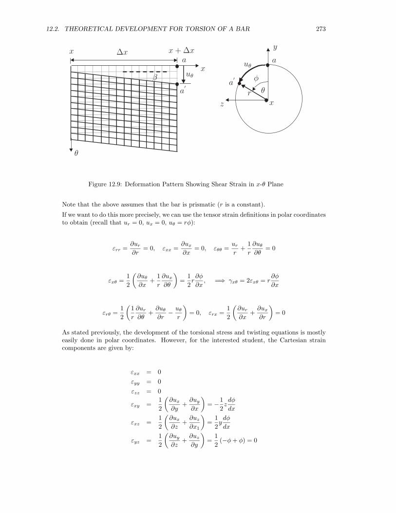
With these kinematic displacement assumptions, the strains may now be evaluated. In orderto determine the strain in polar coordinates, consider the experiment referred to above. If onerolls out the curved surface of the bar into a flat surface, we have the following (for a lengthof the bar between x and x + ∆x):
In the x-θ plane, the angle β represents the change in right angle for one of the original squaresand will define the strain εxθ (or engineering shear strain, γxθ. We can write the following forthe engineering shear strain:
γxθ = β = tan−1
(uθ|x+∆x − uθ|x
∆x
)≈
uθ|x+∆x − uθ|x∆x
=∂uθ
∂x(12.2)
But the displacement is given by: uθ = rφ so that
γxθ = r∂φ
∂x(12.3)
and
εxθ =12γxθ =
12r∂φ
∂x(12.4)
12.2. THEORETICAL DEVELOPMENT FOR TORSION OF A BAR 273
xy
z
x
∆x x + ∆xa
a′
φ
θ
β
r
uθ
θ
a
a′
uθ
x
Figure 12.9: Deformation Pattern Showing Shear Strain in x-θ Plane
Note that the above assumes that the bar is prismatic (r is a constant).
If we want to do this more precisely, we can use the tensor strain definitions in polar coordinatesto obtain (recall that ur = 0, ux = 0, uθ = rφ):
εrr =∂ur
∂r= 0, εxx =
∂ux
∂x= 0, εθθ =
ur
r+
1r
∂uθ
∂θ= 0
εxθ =12
(∂uθ
∂x+
1r
∂ux
∂θ
)=
12r∂φ
∂x, =⇒ γxθ = 2εxθ = r
∂φ
∂x
εrθ =12
(1r
∂ur
∂θ+
∂uθ
∂r− uθ
r
)= 0, εrx =
12
(∂ur
∂x+
∂ux
∂r
)= 0
As stated previously, the development of the torsional stress and twisting equations is mostlyeasily done in polar coordinates. However, for the interested student, the Cartesian straincomponents are given by:
εxx = 0εyy = 0εzz = 0
εxy =12
(∂ux
∂y+
∂uy
∂x
)= −1
2zdφ
dx
εxz =12
(∂ux
∂z+
∂uz
∂x1
)=
12ydφ
dx
εyz =12
(∂uy
∂z+
∂uz
∂y
)=
12
(−φ + φ) = 0
274CHAPTER 12. STRESS AND DEFORMATION ANALYSIS OF LINEAR ELASTIC BARS IN TORSION
• Stresses (Constitutive Equations)
For an elastic, isotropic material, we can write the stress-strain relation as
σxθ =E
(1 + ν)εxθ =
E
(1 + ν)γxθ
2=
E
2(1 + ν)γxθ = Gγxθ (12.5)
where
G = shear modulus =E
2(1 + ν)
• Equilibrium equations (COLM)
Note that these stresses must satisfy the equilibrium equations to be a valid state of stress.The static equilibrium equations reduce to (for the case of no body forces):
y equilibrium : ∂σxy
∂x = 0 =⇒ d2φdx2 = 0
z equilibrium : ∂σzx
∂x = 0 =⇒ d2φdx2 = 0
}=⇒ dφ
dx= constant (12.6)
The last result requires that φ varies linearly with x.
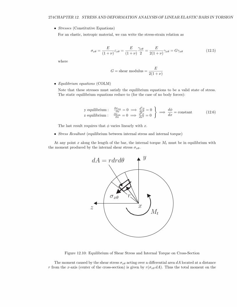
• Stress Resultant (equilibrium between internal stress and internal torque)
At any point x along the length of the bar, the internal torque Mt must be in equilibrium withthe moment produced by the internal shear stress σxθ.
x
y
zMt
dA = rdrdθ
rσxθ
Figure 12.10: Equilibrium of Shear Stress and Internal Torque on Cross-Section
The moment caused by the shear stress σxθ acting over a differential area dA located at a distancer from the x-axis (center of the cross-section) is given by r(σxθ dA). Thus the total moment on the
12.2. THEORETICAL DEVELOPMENT FOR TORSION OF A BAR 275
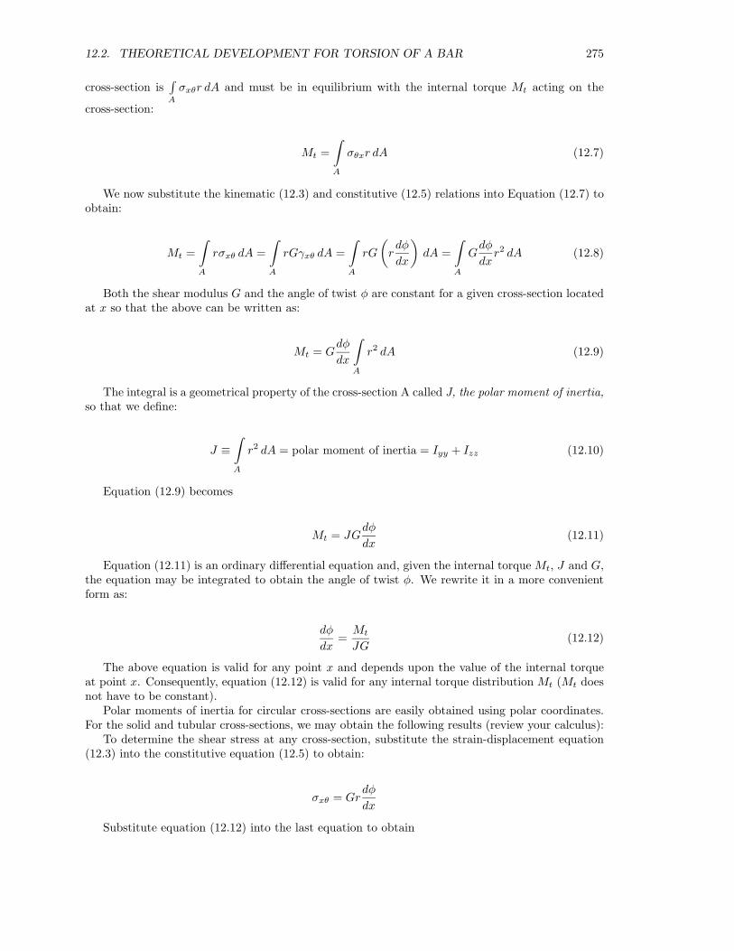
cross-section is∫A
σxθr dA and must be in equilibrium with the internal torque Mt acting on the
cross-section:
Mt =∫A
σθxr dA (12.7)
We now substitute the kinematic (12.3) and constitutive (12.5) relations into Equation (12.7) toobtain:
Mt =∫A
rσxθ dA =∫A
rGγxθ dA =∫A
rG
(rdφ
dx
)dA =
∫A
Gdφ
dxr2 dA (12.8)
Both the shear modulus G and the angle of twist φ are constant for a given cross-section locatedat x so that the above can be written as:
Mt = Gdφ
dx
∫A
r2 dA (12.9)
The integral is a geometrical property of the cross-section A called J, the polar moment of inertia,so that we define:
J ≡∫A
r2 dA = polar moment of inertia = Iyy + Izz (12.10)
Equation (12.9) becomes
Mt = JGdφ
dx(12.11)
Equation (12.11) is an ordinary differential equation and, given the internal torque Mt, J and G,the equation may be integrated to obtain the angle of twist φ. We rewrite it in a more convenientform as:
dφ
dx=
Mt
JG(12.12)
The above equation is valid for any point x and depends upon the value of the internal torqueat point x. Consequently, equation (12.12) is valid for any internal torque distribution Mt (Mt doesnot have to be constant).
Polar moments of inertia for circular cross-sections are easily obtained using polar coordinates.For the solid and tubular cross-sections, we may obtain the following results (review your calculus):
To determine the shear stress at any cross-section, substitute the strain-displacement equation(12.3) into the constitutive equation (12.5) to obtain:
σxθ = Grdφ
dx
Substitute equation (12.12) into the last equation to obtain
276CHAPTER 12. STRESS AND DEFORMATION ANALYSIS OF LINEAR ELASTIC BARS IN TORSION
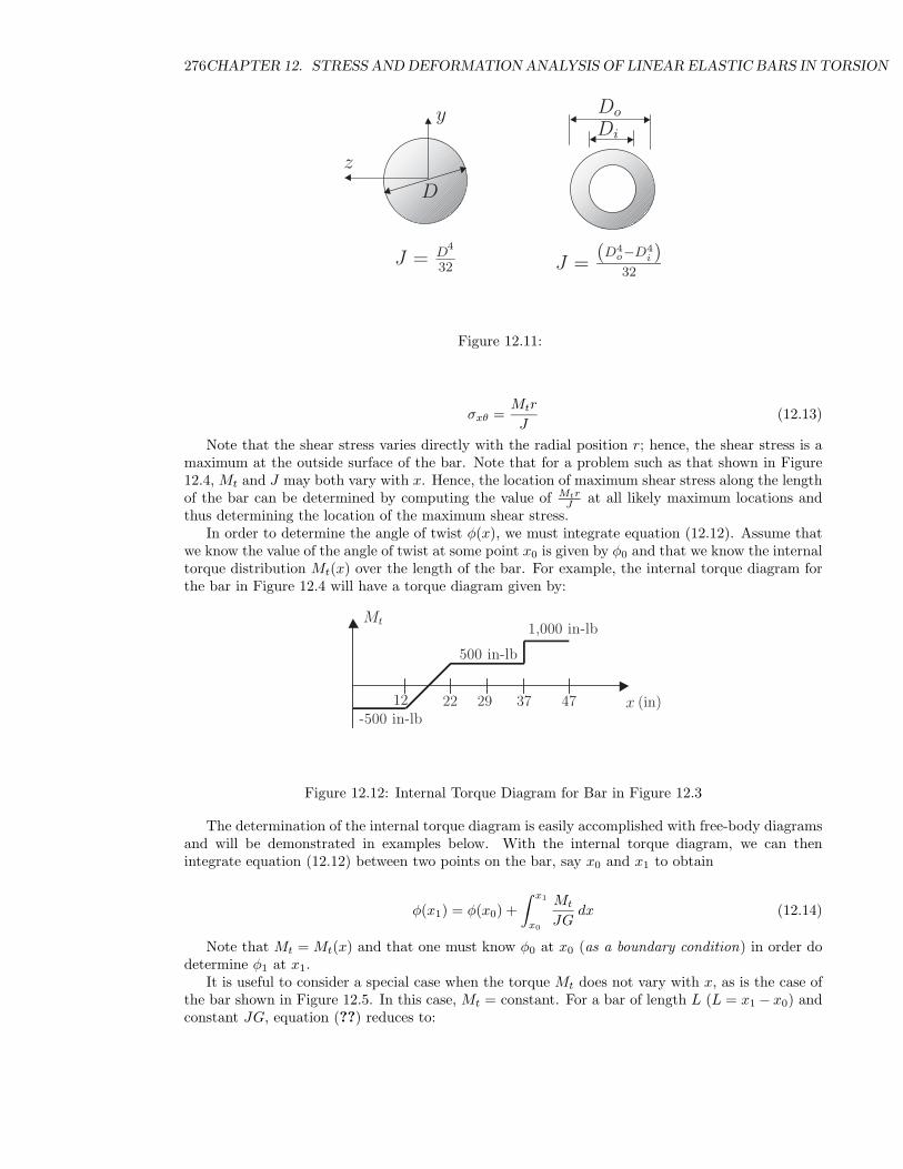
J = D4
32 J =(D4
o−D4i )
32
Do
Di
D
y
z
Figure 12.11:
σxθ =Mtr
J(12.13)
Note that the shear stress varies directly with the radial position r; hence, the shear stress is amaximum at the outside surface of the bar. Note that for a problem such as that shown in Figure12.4, Mt and J may both vary with x. Hence, the location of maximum shear stress along the lengthof the bar can be determined by computing the value of Mtr
J at all likely maximum locations andthus determining the location of the maximum shear stress.
In order to determine the angle of twist φ(x), we must integrate equation (12.12). Assume thatwe know the value of the angle of twist at some point x0 is given by φ0 and that we know the internaltorque distribution Mt(x) over the length of the bar. For example, the internal torque diagram forthe bar in Figure 12.4 will have a torque diagram given by:
500 in-lb
12 22 29 37 47
Mt
x-500 in-lb
1,000 in-lb
(in)
Figure 12.12: Internal Torque Diagram for Bar in Figure 12.3
The determination of the internal torque diagram is easily accomplished with free-body diagramsand will be demonstrated in examples below. With the internal torque diagram, we can thenintegrate equation (12.12) between two points on the bar, say x0 and x1 to obtain
φ(x1) = φ(x0) +∫ x1
x0
Mt
JGdx (12.14)
Note that Mt = Mt(x) and that one must know φ0 at x0 (as a boundary condition) in order dodetermine φ1 at x1.
It is useful to consider a special case when the torque Mt does not vary with x, as is the case ofthe bar shown in Figure 12.5. In this case, Mt = constant. For a bar of length L (L = x1 − x0) andconstant JG, equation (??) reduces to:
12.2. THEORETICAL DEVELOPMENT FOR TORSION OF A BAR 277
φ(L) = φ(x0) +MtL
JG
If the bar is fixed from rotation at x0 = 0 (boundary condition), then equation reduces to
φ(L) =MtL
JG
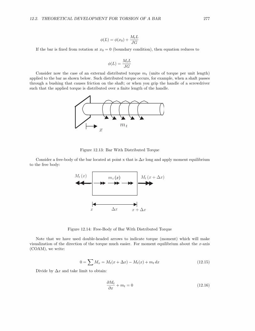
Consider now the case of an external distributed torque mt (units of torque per unit length)applied to the bar as shown below. Such distributed torque occurs, for example, when a shaft passesthrough a bushing that causes friction on the shaft; or when you grip the handle of a screwdriversuch that the applied torque is distributed over a finite length of the handle.
xm t
Figure 12.13: Bar With Distributed Torque
Consider a free-body of the bar located at point x that is ∆x long and apply moment equilibriumto the free body:
x ∆x x + ∆x
Mt (x + ∆x)Mt (x) m t (x)(x)
Figure 12.14: Free-Body of Bar With Distributed Torque
Note that we have used double-headed arrows to indicate torque (moment) which will makevisualization of the direction of the torque much easier. For moment equilibrium about the x-axis(COAM), we write:
0 =∑
Mx = Mt(x + ∆x) − Mt(x) + mt dx (12.15)
Divide by ∆x and take limit to obtain:
∂Mt
∂x+ mt = 0 (12.16)
278CHAPTER 12. STRESS AND DEFORMATION ANALYSIS OF LINEAR ELASTIC BARS IN TORSION
Given the expression for the applied distributed torque mt, the above can be integrated to obtainthe internal torque, Mt(x). We can then substitute Mt(x) into the differential equation defining φ[equation (12.12)] and integrate from x1 to x2 to obtain
φ(x2) = φ(x1) +∫ x2
x1
Mt(x)JG
dx (12.17)
Alternately, we can substitute (12.12) into (12.16) to obtain:
∂
∂x
(JG
dφ
dx
)+ mt = 0 (12.18)
This last equation can be integrated twice to obtain φ(x). However, the solution process maybe conceptually easier to understand by applying equation (12.16) to obtain Mt (need boundarycondition for Mt at some value of x) and then applying equation (12.17) to obtain φ(x) (needboundary condition for φ at some value of x).
12.3 Example Problems
This load frame is set up to do remote torsion experiments on a circular specimen; you can see thecamera in the lower right corner.
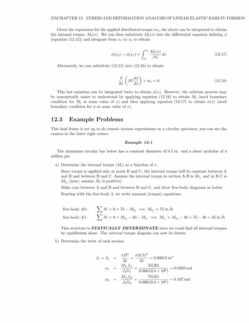
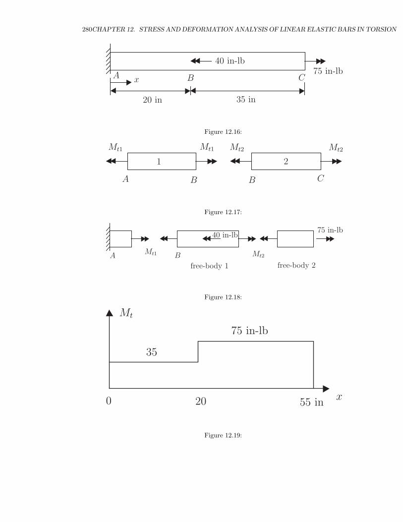
Example 12-1
The aluminum circular bar below has a constant diameter of 0.5 in. and a shear modulus of 4million psi.
a) Determine the internal torque (Mt) as a function of x.
Since torque is applied only at point B and C, the internal torque will be constant between Aand B and between B and C. Assume the internal torque in section A-B is Mt1 and in B-C isMt2 (note: assume Mt is positive).
Make cuts between A and B and between B and C, and draw free-body diagrams as below:
Starting with the free-body 2, we write moment (torque) equations:
free-body #2 :∑
M = 0 = 75 − Mt2 =⇒ Mt2 = 75 in lb
free-body #1 :∑
M = 0 = Mt2 − 40 − Mt1 =⇒ Mt1 = Mt2 − 40 = 75 − 40 = 35 in lb
This structure is STATICALLY DETERMINATE since we could find all internal torquesby equilibrium alone. The internal torque diagram can now be drawn:
b) Determine the twist of each section.
J1 = J2 =πD4
32=
π(0.5)4
32= 0.00613 in4
φ1 =Mt1L1
J1G1=
35(20)0.00613(4 × 10⁶)
= 0.0285 rad
φ2 =Mt2L2
J2G2=
75(35)0.00613(4 × 10⁶)
= 0.107 rad
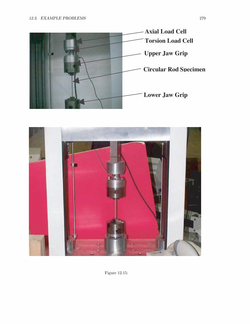
12.3. EXAMPLE PROBLEMS 279
Axial Load Cell
Torsion Load Cell
Upper Jaw Grip
Circular Rod Specimen
Lower Jaw Grip
Figure 12.15:
280CHAPTER 12. STRESS AND DEFORMATION ANALYSIS OF LINEAR ELASTIC BARS IN TORSION
A B C
40 in-lb75 in-lb
x
20 in 35 in
Figure 12.16:
A B C
Mt1 Mt2
1 2
B
Mt1 Mt2
Figure 12.17:
A B
40 in-lb75 in-lb
Mt1 Mt2
free-body 1 free-body 2
Figure 12.18:
75 in-lb
x0
Mt
20 55 in
35
Figure 12.19:
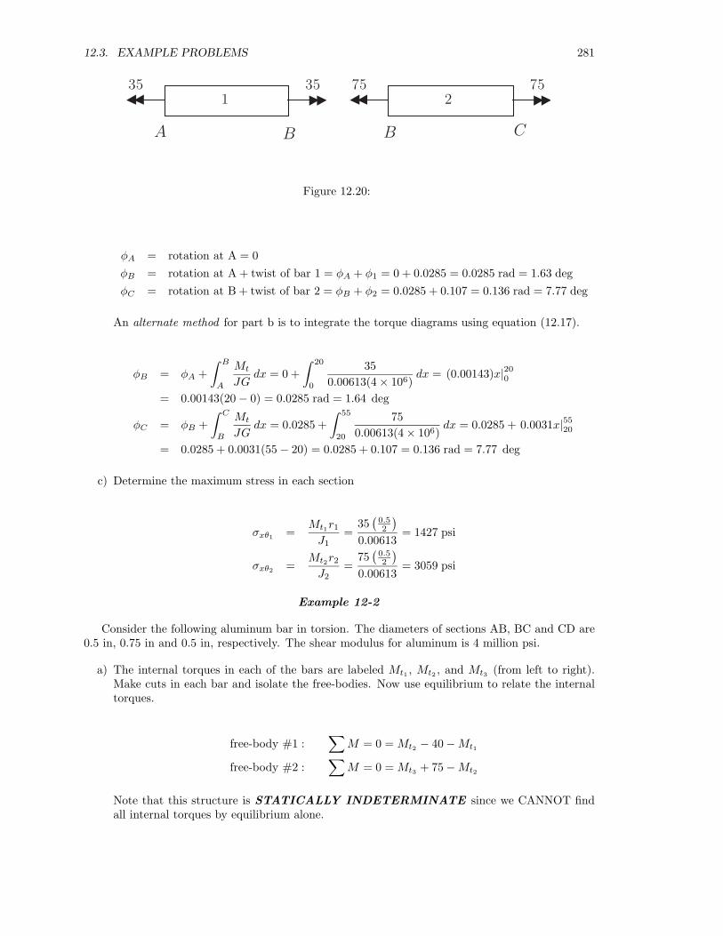
12.3. EXAMPLE PROBLEMS 281
1 235 35 75 75
A B CB
Figure 12.20:
φA = rotation at A = 0φB = rotation at A + twist of bar 1 = φA + φ1 = 0 + 0.0285 = 0.0285 rad = 1.63 degφC = rotation at B + twist of bar 2 = φB + φ2 = 0.0285 + 0.107 = 0.136 rad = 7.77 deg
An alternate method for part b is to integrate the torque diagrams using equation (12.17).
φB = φA +∫ B
A
Mt
JGdx = 0 +
∫ 20
0
350.00613(4 × 10⁶)
dx = (0.00143)x|200= 0.00143(20 − 0) = 0.0285 rad = 1.64 deg
φC = φB +∫ C
B
Mt
JGdx = 0.0285 +
∫ 55
20
750.00613(4 × 10⁶)
dx = 0.0285 + 0.0031x|5520= 0.0285 + 0.0031(55 − 20) = 0.0285 + 0.107 = 0.136 rad = 7.77 deg
c) Determine the maximum stress in each section
σxθ1 =Mt1r1
J1=
35(
0.52
)0.00613
= 1427 psi
σxθ2 =Mt2r2
J2=
75(
0.52
)0.00613
= 3059 psi
Example 12-2
Consider the following aluminum bar in torsion. The diameters of sections AB, BC and CD are0.5 in, 0.75 in and 0.5 in, respectively. The shear modulus for aluminum is 4 million psi.
a) The internal torques in each of the bars are labeled Mt1 , Mt2 , and Mt3 (from left to right).Make cuts in each bar and isolate the free-bodies. Now use equilibrium to relate the internaltorques.
free-body #1 :∑
M = 0 = Mt2 − 40 − Mt1
free-body #2 :∑
M = 0 = Mt3 + 75 − Mt2
Note that this structure is STATICALLY INDETERMINATE since we CANNOT findall internal torques by equilibrium alone.
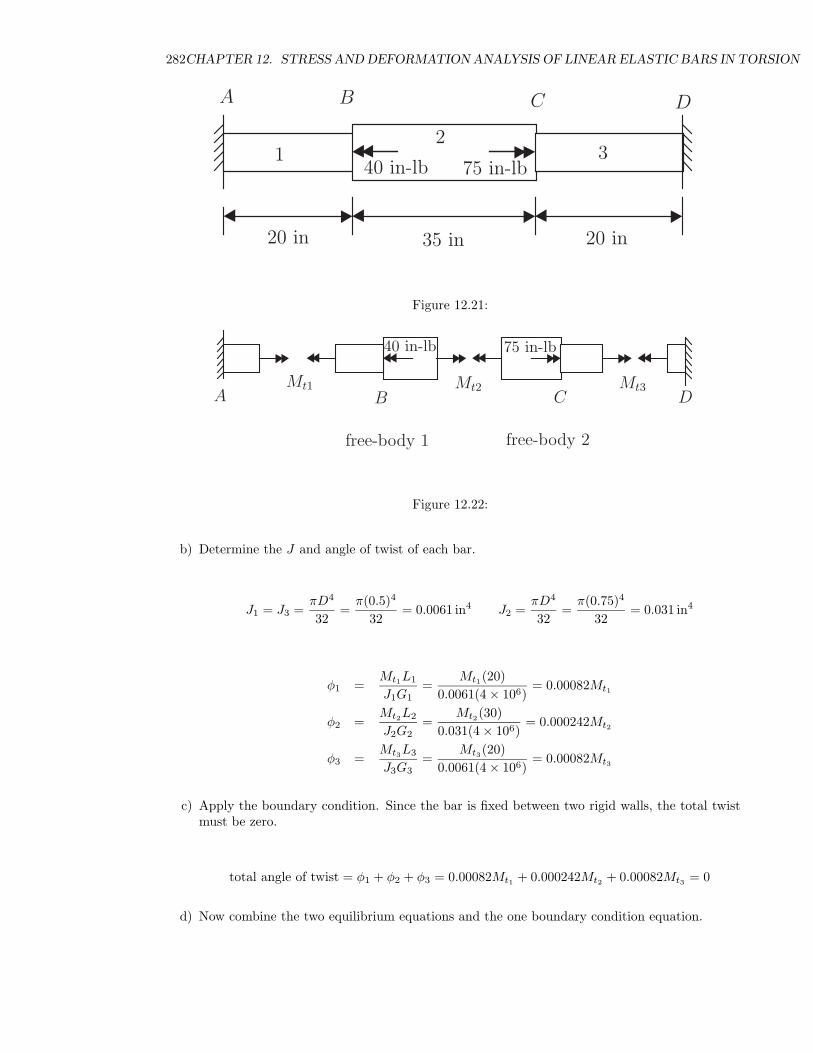
282CHAPTER 12. STRESS AND DEFORMATION ANALYSIS OF LINEAR ELASTIC BARS IN TORSION
A B C
40 in-lb 75 in-lb
20 in
12
35 in 20 in
D
3
Figure 12.21:
A B CMt1 Mt2
free-body 1 free-body 2
Mt3D
40 in-lb 75 in-lb
Figure 12.22:
b) Determine the J and angle of twist of each bar.
J1 = J3 =πD4
32=
π(0.5)4
32= 0.0061 in4 J2 =
πD4
32=
π(0.75)4
32= 0.031 in4
φ1 =Mt1L1
J1G1=
Mt1(20)0.0061(4 × 10⁶)
= 0.00082Mt1
φ2 =Mt2L2
J2G2=
Mt2(30)0.031(4 × 10⁶)
= 0.000242Mt2
φ3 =Mt3L3
J3G3=
Mt3(20)0.0061(4 × 10⁶)
= 0.00082Mt3
c) Apply the boundary condition. Since the bar is fixed between two rigid walls, the total twistmust be zero.
total angle of twist = φ1 + φ2 + φ3 = 0.00082Mt1 + 0.000242Mt2 + 0.00082Mt3 = 0
d) Now combine the two equilibrium equations and the one boundary condition equation.
12.3. EXAMPLE PROBLEMS 283
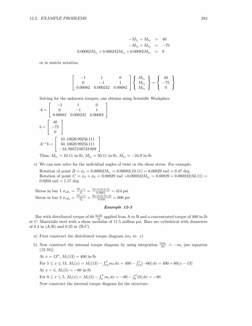
−Mt1 + Mt2 = 40−Mt2 + Mt3 = −75
0.00082Mt1 + 0.000242Mt2 + 0.00082Mt3 = 0
or in matrix notation,
−1 1 0
0 −1 10.00082 0.000242 0.00082
Mt1
Mt2
Mt3
=
40−750
Solving for the unknown torques, one obtains using Scientific Workplace
A =
−1 1 0
0 −1 10.00082 0.000242 0.00082
b =
40
−750
A−1b =
10. 10626 99256 111
50. 10626 99256 111−24. 89373 00743 889
Thus, Mt1 = 10.11 in-lb, Mt2 = 50.11 in-lb, Mt3 = −24.9 in-lb
e) We can now solve for the individual angles of twist or the shear stress. For example,
Rotation of point B = φ1 = 0.00082Mt1 = 0.00082(10.11) = 0.00829 rad = 0.47 degRotation of point C = φ1 + φ2 = 0.00829 rad +0.000242Mt2 = 0.00829 + 0.000242(50.11) =0.0204 rad = 1.17 deg
Stress in bar 1 σxθ1 = Mt1r1
J1= 10.11(0.5/2)
0.0061 = 414 psi
Stress in bar 2 σxθ2 = Mt2r2
J2= 50.11(0.75/2)
0.031 = 606 psi
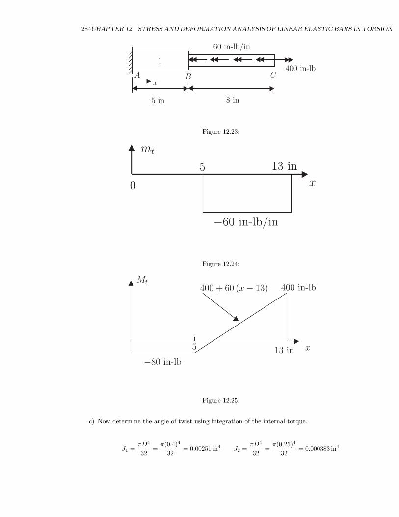
Example 12-3
Bar with distributed torque of 60 in-lbin applied from A to B and a concentrated torque of 400 in-lb
at C. Materialis steel with a shear modulus of 11.5 million psi. Bars are cylindrical with diametersof 0.4 in (A-B) and 0.25 in (B-C).
a) First construct the distributed torque diagram (mt vs. x)
b) Now construct the internal torque diagram by using integration ∂Mt
∂x = −mt [see equation(12.16)]:
At x = 13′′, Mt(13) = 400 in-lb
For 5 ≤ x ≤ 13, Mt(x) = Mt(13) −∫ x
13mt dx = 400 −
∫ x
13(−60) dx = 400 + 60(x − 13)
At x = 5, Mt(5) = −80 in-lb
For 0 ≤ x ≤ 5, Mt(x) = Mt(5) −∫ x
5mt dx = −80 −
∫ x
5(0) dx = −80
Now construct the internal torque diagram for the structure.
284CHAPTER 12. STRESS AND DEFORMATION ANALYSIS OF LINEAR ELASTIC BARS IN TORSION
A B Cx
1
60 in-lb/in
400 in-lb
5 in 8 in
Figure 12.23:
x
mt
0
5 13 in
−60 in-lb/in
Figure 12.24:
x
Mt400 in-lb
5 13 in
−80 in-lb
400 + 60 (x − 13)
Figure 12.25:
c) Now determine the angle of twist using integration of the internal torque.
J1 =πD4
32=
π(0.4)4
32= 0.00251 in4 J2 =
πD4
32=
π(0.25)4
32= 0.000383 in4
12.3. EXAMPLE PROBLEMS 285
for 0 ≤ x ≤ 5, φ(x) = φ(0) +∫ x
0Mt
J1G1dx = 0 +
∫ x
0(−80)
(0.00251)(11×106) dx = −0.0029x
φ(5) = −0.0029(5) = −0.0145 rad = −0.83 deg
for 5 ≤ x ≤ 13,φ(x) = φ(5) +
∫ x
5Mt
J2G2dx = −.0145 +
∫ x
5[400+60(x−13)]
J2G2dx
= −.0145 + 1.000383(11×106) (−380x + 30x2)
∣∣x5
= −0.0145 + 14,213 [−380x + 30x2 + 1150]
φ(13) = −0.0145 + 0.304 = 0.289 rad = 16.6 deg
d) Now determine stresses at various x points. Be sure to use Mt, r and J for desired x value.
At x = 5 in, σxθ(x = 5) = Mt(x=5)rJ1
=−80( 0.4
2 )0.00251 = −6375 psi
At x = 9 in, σxθ(x = 9) = Mt(x=9)rJ2
=160( 0.25
2 )0.000383 = 52219 psi
At x = 13 in, σxθ(x = 13) = Mt(x=13)rJ2
=400( 0.25
2 )0.000383 = 130, 550 psi
Note: depending upon the type of steel, the material may fail before reaching a shear stress of130 ksi.
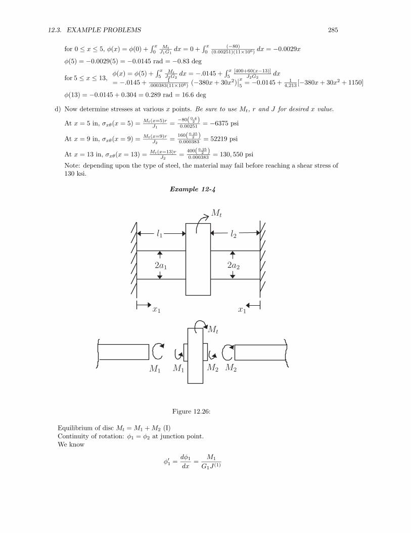
Example 12-4
Mt
l1 l2
2a1 2a2
M1 M2
x1 x1
M1
Mt
M2
Figure 12.26:
Equilibrium of disc Mt = M1 + M2 (I)Continuity of rotation: φ1 = φ2 at junction point.We know
φ′1 =
dφ1
dx=
M1
G1J (1)
286CHAPTER 12. STRESS AND DEFORMATION ANALYSIS OF LINEAR ELASTIC BARS IN TORSION
therefore by integration
φ1 =M1
G1J (1)x1 + c, x1 = 0, φ1 = 0 =⇒ c = 0
φ1 (x1 = 1) =M11
G1J (1)(1)
We do the same for φ′2:
φ′2 =
M2
G2J (2)=⇒ φ2 =
M2
G2J (2)x1 + c, x1 = 0, φ2 = 0 =⇒ c = 0
φ2 (x1 = 2) =M22
G2J (2)(2)
Using (1) & (2) =⇒ M1�1G1J(1) = M2�2
G2J(2) =⇒ M1�1
G1πa4
12
= M2�2
G2πa4
22
=⇒ M1�1G1a4
1= M2�2
G2a42
(II)
Using (I) & (II) =⇒ M1�1G1a4
1= (Mt−M1)�2
G2a42
M1
(1
G1a41
+2
G2a42
)= Mt
2G2a4
2
∴ M1 = �2G2a4
2
(�1
G1a41
+ �2G2a4
2
)−1
Mt
M2 = �1G1a4
1
(�1
G1a41
+ �2G2a4
2
)−1
Mt
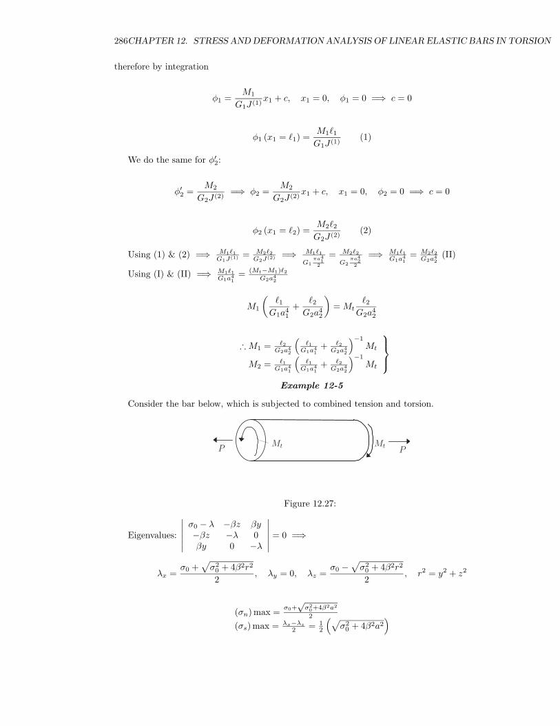
Example 12-5
Consider the bar below, which is subjected to combined tension and torsion.
Mt MtP P
Figure 12.27:
Eigenvalues:
∣∣∣∣∣∣σ0 − λ −βz βy−βz −λ 0βy 0 −λ
∣∣∣∣∣∣ = 0 =⇒
λx =σ0 +
√σ2
0 + 4β2r2
2, λy = 0, λz =
σ0 −√
σ20 + 4β2r2
2, r2 = y2 + z2
(σn) max = σ0+√
σ20+4β2a2
2
(σs) max = λx−λz
2 = 12
(√σ2
0 + 4β2a2)
12.3. EXAMPLE PROBLEMS 287
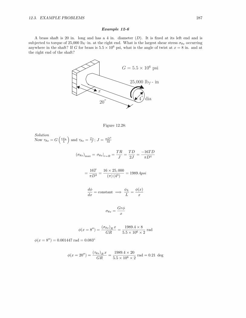
Example 12-6
A brass shaft is 20 in. long and has a 4 in. diameter (D). It is fixed at its left end and issubjected to torque of 25,000 lbf · in. at the right end. What is the largest shear stress σθx occurringanywhere in the shaft? If G for brass is 5.5× 10⁶ psi, what is the angle of twist at x = 8 in. and atthe right end of the shaft?
x
20′′ 4
′′dia
25,000 lbf - in
G = 5.5 × 10⁶ psi
Figure 12.28:
SolutionNow τθx = G
(rφL
L
)and τθx = Tr
J ; J = πD4
32
(σθx)max = σθx|r=R =TR
J=
TD
2J=
−16TD
πD4
=16T
πD3=
16 × 25, 000(π) (43)
= 1989.4psi
dφ
dx= constant =⇒ φL
L=
φ(x)x
σθx =Grφ
x
φ(x = 8′′) =(σθx)R x
GR=
1989.4 × 85.5 × 106 × 2
rad
φ(x = 8′′) = 0.001447 rad = 0.083◦
φ(x = 20′′) =(τθx)R x
GR=
1989.4 × 205.5 × 106 × 2
rad = 0.21 deg
288CHAPTER 12. STRESS AND DEFORMATION ANALYSIS OF LINEAR ELASTIC BARS IN TORSION
Deep Thought
Torsion: A threat to mankind !
12.4. QUESTIONS 289
12.4 Questions
12.1 Provide the stress tensor for the case of a circular rod in pure torsion by indicating the tensor’scomponents with appropriate variables and/or zeros in a 3 × 3 matrix array.
12.2 Repeat 12.1 for the strain tensor, again using appropriate variables and/or zeros in a 3 × 3matrix array.
12.5 Problems
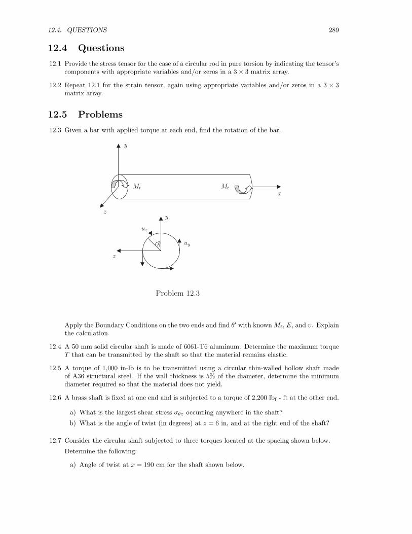
12.3 Given a bar with applied torque at each end, find the rotation of the bar.
x
y
z
uz
uyθ
Mt Mt
z
y
Problem 12.3
Apply the Boundary Conditions on the two ends and find θ′ with known Mt, E, and υ. Explainthe calculation.
12.4 A 50 mm solid circular shaft is made of 6061-T6 aluminum. Determine the maximum torqueT that can be transmitted by the shaft so that the material remains elastic.
12.5 A torque of 1,000 in-lb is to be transmitted using a circular thin-walled hollow shaft madeof A36 structural steel. If the wall thickness is 5% of the diameter, determine the minimumdiameter required so that the material does not yield.
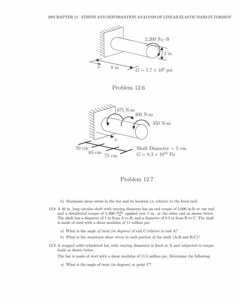
12.6 A brass shaft is fixed at one end and is subjected to a torque of 2,200 lbf - ft at the other end.
a) What is the largest shear stress σθz occurring anywhere in the shaft?
b) What is the angle of twist (in degrees) at z = 6 in, and at the right end of the shaft?
12.7 Consider the circular shaft subjected to three torques located at the spacing shown below.
Determine the following:
a) Angle of twist at x = 190 cm for the shaft shown below.
290CHAPTER 12. STRESS AND DEFORMATION ANALYSIS OF LINEAR ELASTIC BARS IN TORSION
x
2,200 lbf -ft
2 in
8 inG = 5.7 × 10⁶ psi
Problem 12.6
x
475 N-m400 N-m
350 N-m
50 cm65 cm
75 cm
Shaft Diameter = 5 cmG = 8.3 × 10¹⁰ Pa
Problem 12.7
b) Maximum shear stress in the bar and its location (x, relative to the fixed end).
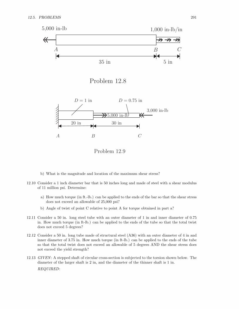
12.8 A 40 in. long circular shaft with varying diameter has an end torque of 5,000 in-lb at one endand a distributed torque of 1, 000 in-lb.
in applied over 5 in. at the other end as shown below.The shaft has a diameter of 1 in from A to B, and a diameter of 0.5 in from B to C. The shaftis made of steel with a shear modulus of 11 million psi.
a) What is the angle of twist (in degrees) of end C relative to end A?
b) What is the maximum shear stress in each portion of the shaft (A-B and B-C)?
12.9 A stepped solid cylindrical bar with varying diameters is fixed at A and subjected to torqueloads as shown below.
The bar is made of steel with a shear modulus of 11.5 million psi. Determine the following:
a) What is the angle of twist (in degrees) at point C?
12.5. PROBLEMS 291
5,000 in-lb 1,000 in-lb/in
35 in 5 in
A B C
Problem 12.8
5,000 in-lb
A B C
D = 1 in D = 0.75 in
20 in 30 in
3,000 in-lb
Problem 12.9
b) What is the magnitude and location of the maximum shear stress?
12.10 Consider a 1 inch diameter bar that is 50 inches long and made of steel with a shear modulusof 11 million psi. Determine:
a) How much torque (in ft.-lb.) can be applied to the ends of the bar so that the shear stressdoes not exceed an allowable of 25,000 psi?
b) Angle of twist of point C relative to point A for torque obtained in part a?
12.11 Consider a 50 in. long steel tube with an outer diameter of 1 in and inner diameter of 0.75in. How much torque (in ft-lb.) can be applied to the ends of the tube so that the total twistdoes not exceed 5 degrees?
12.12 Consider a 50 in. long tube made of structural steel (A36) with an outer diameter of 4 in andinner diameter of 3.75 in. How much torque (in ft-lb.) can be applied to the ends of the tubeso that the total twist does not exceed an allowable of 5 degrees AND the shear stress doesnot exceed the yield strength?
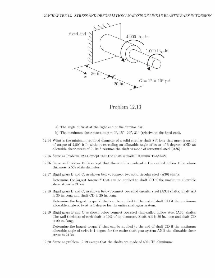
12.13 GIVEN : A stepped shaft of circular cross-section is subjected to the torsion shown below. Thediameter of the larger shaft is 2 in, and the diameter of the thinner shaft is 1 in.
REQUIRED :
292CHAPTER 12. STRESS AND DEFORMATION ANALYSIS OF LINEAR ELASTIC BARS IN TORSION
30 in
20 in
fixed end
G = 12 × 106 psi
4,000 lbf -in
1,000 lbf -in
x
Problem 12.13
a) The angle of twist at the right end of the circular bar.
b) The maximum shear stress at x = 0′′, 15′′, 29′′, 31′′ (relative to the fixed end).
12.14 What is the minimum required diameter of a solid circular shaft 8 ft long that must transmitof torque of 2,500 ft-lb without exceeding an allowable angle of twist of 5 degrees AND anallowable shear stress of 21 ksi? Assume the shaft is made of structural steel (A36).
12.15 Same as Problem 12.14 except that the shaft is made Titanium Ti-6M-4V.
12.16 Same as Problem 12.14 except that the shaft is made of a thin-walled hollow tube whosethickness is 5% of its diameter.
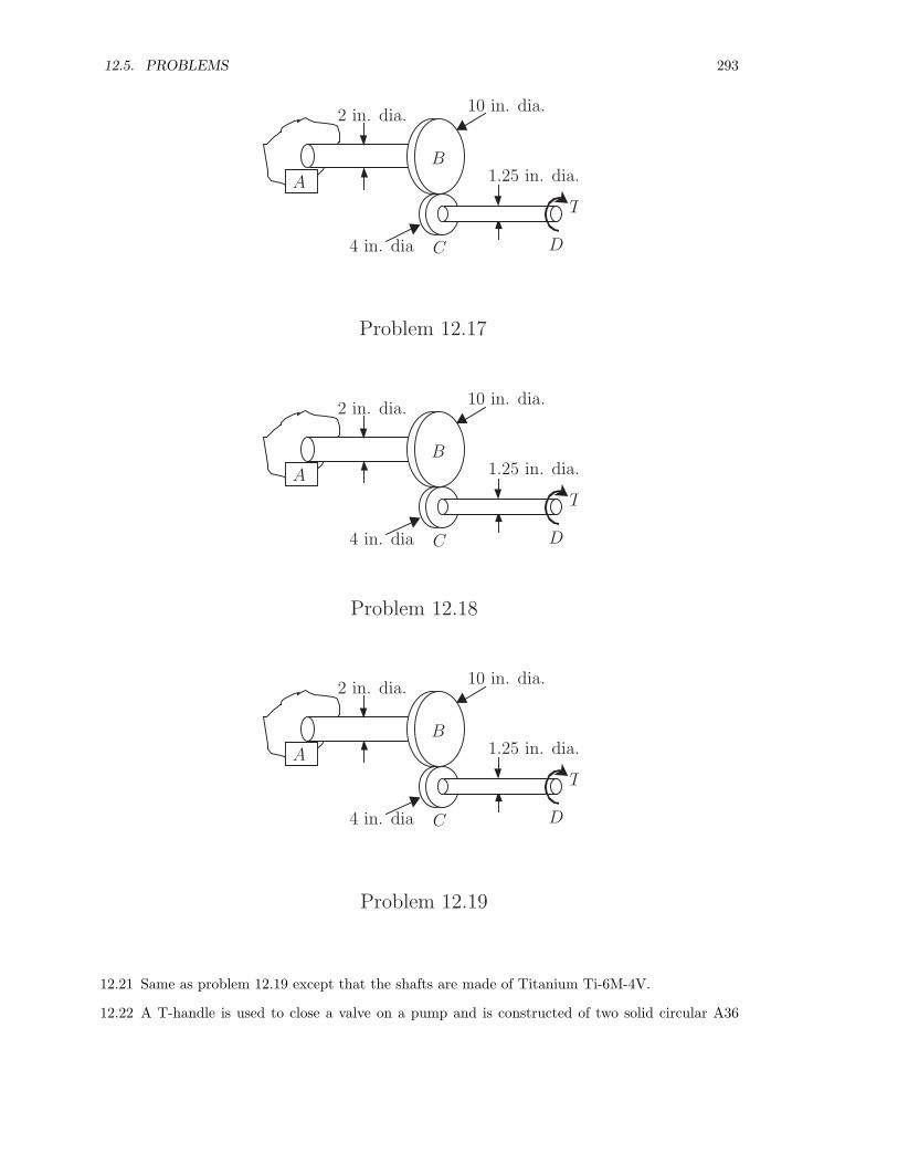
12.17 Rigid gears B and C, as shown below, connect two solid circular steel (A36) shafts.
Determine the largest torque T that can be applied to shaft CD if the maximum allowableshear stress is 21 ksi.
12.18 Rigid gears B and C, as shown below, connect two solid circular steel (A36) shafts. Shaft ABis 30 in. long and shaft CD is 20 in. long.
Determine the largest torque T that can be applied to the end of shaft CD if the maximumallowable angle of twist is 1 degree for the entire shaft-gear system.
12.19 Rigid gears B and C as shown below connect two steel thin-walled hollow steel (A36) shafts.The wall thickness of each shaft is 10% of its diameter. Shaft AB is 30 in. long and shaft CDis 20 in. long.
Determine the largest torque T that can be applied to the end of shaft CD if the maximumallowable angle of twist is 1 degree for the entire shaft-gear system AND the allowable shearstress is 21 ksi.
12.20 Same as problem 12.19 except that the shafts are made of 6061-T6 aluminum.
12.5. PROBLEMS 293
A
B
C D
2 in. dia.10 in. dia.
4 in. dia
1.25 in. dia.
T
Problem 12.17
A
B
C D
2 in. dia.10 in. dia.
4 in. dia
1.25 in. dia.
T
Problem 12.18
A
B
C D
2 in. dia.10 in. dia.
4 in. dia
1.25 in. dia.
T
Problem 12.19
12.21 Same as problem 12.19 except that the shafts are made of Titanium Ti-6M-4V.
12.22 A T-handle is used to close a valve on a pump and is constructed of two solid circular A36
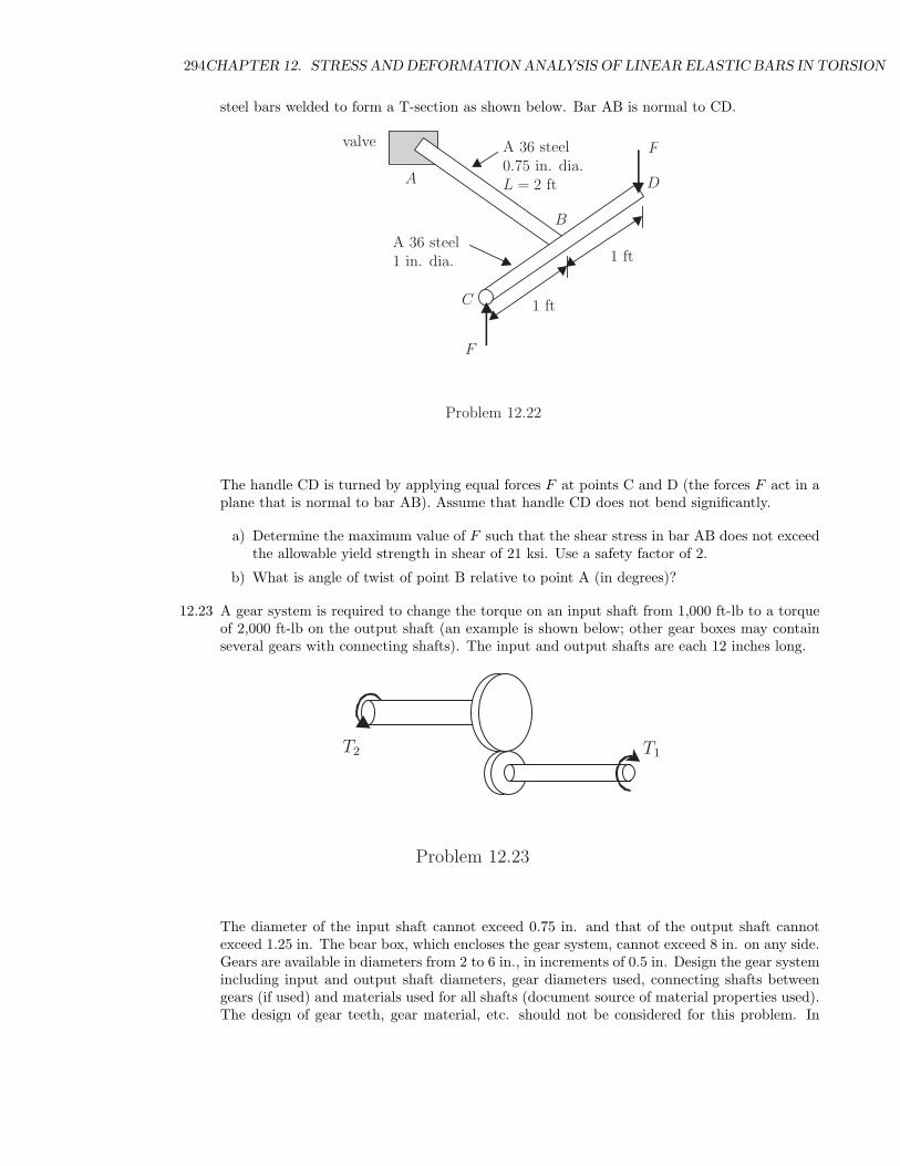
294CHAPTER 12. STRESS AND DEFORMATION ANALYSIS OF LINEAR ELASTIC BARS IN TORSION
steel bars welded to form a T-section as shown below. Bar AB is normal to CD.
valve
A 36 steel1 in. dia.
A 36 steel0.75 in. dia.L = 2 ft
1 ft
1 ft
F
F
A
B
C
D
Problem 12.22
The handle CD is turned by applying equal forces F at points C and D (the forces F act in aplane that is normal to bar AB). Assume that handle CD does not bend significantly.
a) Determine the maximum value of F such that the shear stress in bar AB does not exceedthe allowable yield strength in shear of 21 ksi. Use a safety factor of 2.
b) What is angle of twist of point B relative to point A (in degrees)?
12.23 A gear system is required to change the torque on an input shaft from 1,000 ft-lb to a torqueof 2,000 ft-lb on the output shaft (an example is shown below; other gear boxes may containseveral gears with connecting shafts). The input and output shafts are each 12 inches long.
T1T2
Problem 12.23
The diameter of the input shaft cannot exceed 0.75 in. and that of the output shaft cannotexceed 1.25 in. The bear box, which encloses the gear system, cannot exceed 8 in. on any side.Gears are available in diameters from 2 to 6 in., in increments of 0.5 in. Design the gear systemincluding input and output shaft diameters, gear diameters used, connecting shafts betweengears (if used) and materials used for all shafts (document source of material properties used).The design of gear teeth, gear material, etc. should not be considered for this problem. In
12.5. PROBLEMS 295
addition to the constraint on input and output shaft diameter, the following requirements mustbe met:
– Use a safety factor of 1.4 when considering the yield strength for the shaft material.
– Design the gear system for minimum weight.
– The total angle of twist for the input and output shafts cannot exceed 5 degrees (end ofinput shaft relative to end of output shaft).
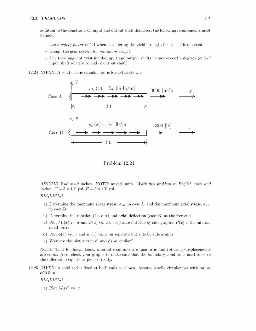
12.24 GIVEN : A solid elastic circular rod is loaded as shown:
Case A
Case B
x
y
mt (x) = 5x [in-lb/in]
px (x) = 5x [lb/in]
3000 [in-lb]
x
y
3000 [lb]
2 ft
2 ft
Problem 12.24
ASSUME : Radius=2 inches. NOTE: mixed units. Work this problem in English units andinches. G = 5 × 10⁵ psi, E = 5 × 10⁵ psi.
REQUIRED :
a) Determine the maximum shear stress, σxθ, in case A, and the maximum axial stress, σxx,in case B.
b) Determine the rotation (Case A) and axial deflection (case B) at the free end.
c) Plot Mt(x) vs. x and P (x) vs. x on separate but side by side graphs. P (x) is the internalaxial force.
d) Plot φ(x) vs. x and ux(x) vs. x on separate but side by side graphs.
e) Why are the plot sets in c) and d) so similar?
NOTE: That for linear loads, internal resultants are quadratic and rotations/displacementsare cubic. Also, check your graphs to make sure that the boundary conditions used to solvethe differential equations plot correctly.
12.25 GIVEN : A solid rod is fixed at both ends as shown. Assume a solid circular bar with radiusof 0.5 in.
REQUIRED :
a) Plot Mt(x) vs. x.

296CHAPTER 12. STRESS AND DEFORMATION ANALYSIS OF LINEAR ELASTIC BARS IN TORSION
x
G = 10 × 106 psi G = 15 × 106 psi G = 10 × 106 psi
15 in
2000 in-lbs
5 in 5 in
3000 in-lbs
Problem 12.25
b) Determine the rotations at both ends.
c) Determine the rotation at x = 5′′ and x = 20′′.
d) Determine the reactions at both ends.
e) Determine the maximum shear stress, σxθ, and it’s x location.
12.26 GIVEN : The axle-gear system shown below:
Problem 12.26
You May Assume That The Circular Gears Are Rigid. Also, the distances from A to B, B toC and C to D are each 18′′.
REQUIRED :
a) What is the value of the force, F?
b) Using A36 Steel, determine the minimum diameters of each of the sections (AB,BC,CD)so that the material does not yield.
c) Determine the angle of twist of D relative to A.