STRESS ANALYSIS SPUR GEAR DESIGN BY USING ANSYS · PDF filethis paper using ansys work bench...
5
STRESS ANALYSIS SPUR GEAR DESIGN BY USING ANSYS WORKBENCH Pradeep Kumar Singh 1 , Manwendra Gautam 1 , Gangasagar 1 and Shyam Bihari Lal 1 * *Corresponding Author: Shyam Bihari Lal, [email protected] A gear is a rotating machine part having cut tooth, which mesh with another toothed part in order to transmit torque. Gears are mainly type like spur gears, helical gears, double helical gears, bevel gears, crown gears, hypoid gears, worm gears, rack and pinion, epicyclic gears etc. The application of these gears fled from tiny wrist watches to huge machinery equipment gears from vital elements of mechanism in many machines such as automobile, aerospace industry, rolling mills, hoisting and transmitting machinery, marine engines, and the like. Parallel and co-planer shaft connected by gears are known as spur gear. Spur gear have straight tooth and are parallel to the axis of the wheel. Spur gears are most common type of gears. A pair of spur gear tooth in action is generally subjected to two types of cyclic stress: contact stress and bending stress including bending fatigue. Both stress may not attain their maximum values at the same point of contact fatigue. These types of failure can be minimized by analysis of the problem during the design stage and creating proper tooth surface profile with proper manufacturing methods. In this paper using ansys work bench software, bending stress, contact stress and static load on the tooth of spur gear drive is found. Keywords: Bending stress, Contact stress, Gear analysis using, Ansys work bench, Static load INTRODUCTION Due to globalization industries are facing competition. It becomes more and necessary to consider alternative technology of manufacturing materials used for gears (Meenakshi et al., 2012). The high volume production industry such as automobile industry has various ISSN 2278 – 0149 www.ijmerr.com Vol. 3, No. 3, July 2014 © 2014 IJMERR. All Rights Reserved Int. J. Mech. Eng. & Rob. Res. 2014 1 Department of Mechanical Engineering, Buddha Institute of Technology, GIDA Gorakhpur, India. manufacturing materials used gears like metal removal method, casting and forming method, but that method which is more suitable containing finishing operations optimal utilization of raw materials, short-cycle times and favorable energy consumptions, compared to convectional manufacturing technology (Rattan, 1998). Research Paper
Transcript of STRESS ANALYSIS SPUR GEAR DESIGN BY USING ANSYS · PDF filethis paper using ansys work bench...

64
Int. J. Mech. Eng. & Rob. Res. 2014 Shyam Bihari Lal et al., 2014
STRESS ANALYSIS SPUR GEAR DESIGN BY USINGANSYS WORKBENCH
Pradeep Kumar Singh1, Manwendra Gautam1, Gangasagar1 and Shyam Bihari Lal1*
*Corresponding Author: Shyam Bihari Lal, [email protected]
A gear is a rotating machine part having cut tooth, which mesh with another toothed part in orderto transmit torque. Gears are mainly type like spur gears, helical gears, double helical gears,bevel gears, crown gears, hypoid gears, worm gears, rack and pinion, epicyclic gears etc. Theapplication of these gears fled from tiny wrist watches to huge machinery equipment gears fromvital elements of mechanism in many machines such as automobile, aerospace industry, rollingmills, hoisting and transmitting machinery, marine engines, and the like. Parallel and co-planershaft connected by gears are known as spur gear. Spur gear have straight tooth and are parallelto the axis of the wheel. Spur gears are most common type of gears. A pair of spur gear tooth inaction is generally subjected to two types of cyclic stress: contact stress and bending stressincluding bending fatigue. Both stress may not attain their maximum values at the same point ofcontact fatigue. These types of failure can be minimized by analysis of the problem during thedesign stage and creating proper tooth surface profile with proper manufacturing methods. Inthis paper using ansys work bench software, bending stress, contact stress and static load onthe tooth of spur gear drive is found.
Keywords: Bending stress, Contact stress, Gear analysis using, Ansys work bench, Staticload
INTRODUCTIONDue to globalization industries are facingcompetition. It becomes more and necessaryto consider alternative technology ofmanufacturing materials used for gears(Meenakshi et al., 2012).
The high volume production industry suchas automobile industry has various
ISSN 2278 – 0149 www.ijmerr.comVol. 3, No. 3, July 2014
© 2014 IJMERR. All Rights Reserved
Int. J. Mech. Eng. & Rob. Res. 2014
1 Department of Mechanical Engineering, Buddha Institute of Technology, GIDA Gorakhpur, India.
manufacturing materials used gears like metalremoval method, casting and forming method,but that method which is more suitablecontaining finishing operations optimalutilization of raw materials, short-cycle timesand favorable energy consumptions,compared to convectional manufacturingtechnology (Rattan, 1998).
Research Paper

65
Int. J. Mech. Eng. & Rob. Res. 2014 Shyam Bihari Lal et al., 2014
Now days, there are so many mechanismsthose involve with load and requirement tounderstand the stress in component isincreased. The mechanisms and the stressalways come together and they have a strongrelation between each other (Romlay, 2008).
Gears is a rotating cylindrical wheel havingtooth cut on it and which meshes with anothertoothed part to transmit the power or torque.Spur gear is the simplest type of gear havingat tooth cut parallel to the axis of shaft on whichthe gear is mounted. Spur gears are used totransmit the power between parallel shafts.Spur gear give 98-99% operating efficiency(Vivek Karaveer et al., 2013).
There are several kinds of stresses presentin loaded and rotating gear teeth. We have toconsider all the possibilities, so that the gearsare proportional to keep all the stresses within design limit. Generally stresses calculatedin gear design formula are not necessary truestress, can make it difficult to get correctanswer on gear-tooth stresses, because it maynot be known whether load is uniformlydistributed across the face width and whetherproperly shared by the two or more pairs ofteeth that are in mesh at the same time. Sowe have to make right assumption that willallow for things like stress concentration,residual stress, misalignment and tooth error(Sushil Kumar Tiwari and Upendra KumarJoshi, 2012).
There are two theoretical formulas, whichdeal with these two fatigue failure mechanism.One is the Hertz equation, which can be usedto calculate the bending stress (Shinde et al.,2012).
The finite element method is capable ofproviding this information but it is time taken,
the time need to create such a model is large.In order to reduce the modeling software canbe used. One such model is provided by ansyswork bench.
FINITE ELEMENT METHODThe finite element method is numericalanalysis technical of optioning approximatesolution to a wide verity of engineeringproblems. because of its diversity andflexibility as an analysis tool, it is receivingmuch attention in engineering school andindustries in more and more engineeringsituation today, we find that it is necessary toobtain approximate solution to problemsrather than exact close from solution it is notpossible to obtain analytical mathematicalsolutions are many engineering’s problems.An analytical solution is a mathematicalexpression that gives value of the desireunknown quantity an any location in the body,as consequence it is valid for infinite numberof location in the body. For problem involvingcomplex material properties and boundercondition, the engineer resource to numericalmethod that provide approximate that eatablesolution.
METHODOLOGYProcedure of Static AnalysisFirst of all, we have prepared assembly in Pro/E for spur gear and save as this part as IGESfor Exporting into ANSYS workbenchEnvironment. Import IGES mode in ANSYSworkbench simulation module. Apply materialfor spur gear (structural steel).
Meshing CriteriaElement type solid 10 node quadratictetrahedral.

66
Int. J. Mech. Eng. & Rob. Res. 2014 Shyam Bihari Lal et al., 2014
Figure 1: Part Design of Spur Gear
Figure 2: Mess of the Gear
Figure 3: Shear Stresses
Figure 5: Middle Principal Stress
Figure 4: Directional Deformation
Figure 6: Minimum Principal Stress
67
Int. J. Mech. Eng. & Rob. Res. 2014 Shyam Bihari Lal et al., 2014
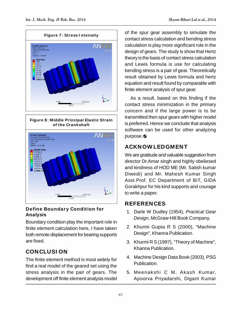
of the spur gear assembly to simulate thecontact stress calculation and bending stresscalculation is play more significant role in thedesign of gears. The study is show that Hertztheory is the basis of contact stress calculationand Lewis formula is use for calculatingbending stress is a pair of gear. Theoreticallyresult obtained by Lewis formula and hertzequation and result found by comparable withfinite element analysis of spur gear.
As a result, based on this finding if thecontact stress minimization in the primaryconcern and if the large power is to betransmitted then spur gears with higher modelis preferred. Hence we conclude that analysissoftware can be used for other analyzingpurpose.
ACKNOWLEDGMENTWe are gratitude and valuable suggestion fromdirector Dr.Amar singh and highly obeliesedand kindness of HOD ME (Mr. Satish kumarDiwedi) and Mr. Mahesh Kumar SinghAsst.Prof. EC Department of BIT, GIDAGorakhpur for his kind supports and courageto write a paper.
REFERENCES1. Darle W Dudley (1954), Practical Gear
Design, McGraw-Hill Book Company.
2. Khurmi Gupta R S (2000), “MachineDesign”, Khanna Publication.
3. Khurmi R S (1997), “Theory of Machine”,Khanna Publication.
4. Machine Design Data Book (2003), PSGPublication.
5. Meenakshi C M, Akash Kumar,Apoorva Priyadarshi, Digant Kumar
Figure 7: Stress Intensity
Figure 8: Middle Principal Elastic Strainof the Crankshaft
Define Boundary Condition forAnalysisBoundary condition play the important role infinite element calculation here, I have takenboth remote displacement for bearing supportsare fixed.
CONCLUSIONThe finite element method is most widely forfind a real model of the geared set using thestress analysis in the pair of gears. Thedevelopment off finite element analysis model

68
Int. J. Mech. Eng. & Rob. Res. 2014 Shyam Bihari Lal et al., 2014
Dash and Hare Krishna (2012),“Analysis of Spur Gear Using FiniteElement Analysis”, Middle-EastJournal of Scient i f ic Research ,Vol. 12, No. 12, pp. 1672-1674.
6. Rattan S S (1998), “Theory of Machines”,Dhanpat Rai Publication.
7. Romlay F R M (2008), “Modeling of aSurface Contact Stress for Spur GearMechanism Using Static and TransientFinite Element Method”, Journal ofStructural Durability & Health Monitoring(SDHM), Vol. 4, No. 1, Tech SciencePress.
8. Shanavas S (2013), “Stress Analysis ofComposite Spur Gear”, InternationalJournal of Engineering Research &Technology (IJERT), ISSN: 2278-0181.
9. Shinde S P, Nikam A and Mulla T S(2012), “Static Analysis of Spur GearUsing Finite Element Analysis”, IOSRJournal of Mechanical and CivilEngineering (IOSR-JMCE), pp. 26-31,ISSN: 2278-1684.
10. Sushil Kumar Tiwari and Upendra KumarJoshi (2012), “Stress Analysis of MatingInvolute Spur Gear Teeth”, InternationalJournal of Engineering Research &Technology (IJERT), Vol. 1, No. 9, ISSN:2278-0181.
11. Vivek Karaveer, Ashish Mogrekar andPreman Reynold Joseph T (2013),“Modeling and Finite Element Analysis ofSpur Gear”, International Journal ofCurrent Engineering and Technology,ISSN 2277-4106.