STRESS ANALYSIS OF THE VARIOUS DIMENSIONS …umpir.ump.edu.my/2986/1/CD6127.pdf · Laporan ini...
33
STRESS ANALYSIS OF THE VARIOUS DIMENSIONS OF THE SPRING ZAJALARA BINTI MAT LAZI Report submitted in partial fulfillment of the requirement for the award of Diploma of Mechanical Engineering Faculty of Mechanical Engineering UNIVERSITI MALAYSIA PAHANG JANUARY 2012
Transcript of STRESS ANALYSIS OF THE VARIOUS DIMENSIONS …umpir.ump.edu.my/2986/1/CD6127.pdf · Laporan ini...

STRESS ANALYSIS OF THE VARIOUS DIMENSIONS OF THE SPRING
ZAJALARA BINTI MAT LAZI
Report submitted in partial fulfillment of the requirement for the award of
Diploma of Mechanical Engineering
Faculty of Mechanical Engineering
UNIVERSITI MALAYSIA PAHANG
JANUARY 2012

vi
ABSTRACT
This report deals with propose of new dimension of the spring to the suspension
system. The objective of this project is to analyze the effect of the spring
performance when we modified the dimension of the spring. The new design of the
spring will be drawn by using SolidWorks® software. Then this a few dimension of
the spring will be testing by using MSC. Nastran/Patran software. This software was
used to analyze the stress on the different dimension of the springs. The stress
results of the different dimensions were observed and recorded. The stress values
indicated that the one of the new dimension of the spring can withstand the highest
stress compared to the other spring.

vii
ABSTRAK
Laporan ini membincangkan dengan mencadangkan dimensi baru spring kepada
sistem suspensi. Objektif projek ini adalah untuk menganalisis kesan prestasi pegas
apabila kita mengubah suai dimensi pegas. Reka bentuk baru pegas akan dilukis
dengan menggunakan perisian SolidWorks®. Kemudian ini dimensi beberapa pegas
akan diuji dengan menggunakan MSC. Perisian Nastran / Patran. Perisian ini telah
digunakan untuk menganalisis tekanan pada dimensi yang berbeza, pegas. Keputusan
tekanan dimensi yang berbeza diperhatikan dan direkodkan. Nilai tekanan yang
menyatakan bahawa salah satu dimensi baru pegas boleh menahan tekanan yang
tertinggi berbanding dengan pegas lain.

viii
TABLE OF CONTENTS
Page
SUPERVISOR’S DECLARATION ii
STUDENT’S DECLARATION iii
ACKNOWLEDGEMENT v
ABSTRACT vi
ABSTRAK vii
TABLE OF CONTENTS viii
LIST OF TABLES xi
LIST OF FIGURES xii
LIST OF SYMBOLS xiii
LIST OF ABBREVIATIONS xiv
CHAPTER 1 INTRODUCTION
1.1 Project Background 2
1.2 Problem Statement 2
1.3 Objective 2
1.4 Project Scopes 2
1.5 Organization of thesis 2
CHAPTER 2 LITERATURE REVIEW
2.1 Suspension System 5
2.2 Vibration 7
2.3 Coil Spring 8
2.4 Chromium Steel 9

ix
CHAPTER 3 METHODOLOGY
3.1 Introduction 12
3.2 Project flowchart 13
3.3 Measurement Tool 14
3.4 Actual design of spring 15
3.5 Parameter of spring
3.5.1 Variable 16
3.5.2 Constant 17
3.6 Design of the different dimension of the spring
3.6.1 First Design 18
3.6.2 Second Design 19
3.6.3 Third Design 20
3.7 Stress Analysis 22
CHAPTER 4 RESULTS AND DISCUSSION
4.1 Introduction 24
4.2 Stress Analysis Results 25
CHAPTER 5 CONCLUSION AND RECOMMENDATION
5.1 Introduction 27
5.2 Conclusion 28
5.3 Recommendation 29
REFERENCES 30
APPENDICES A 31
x
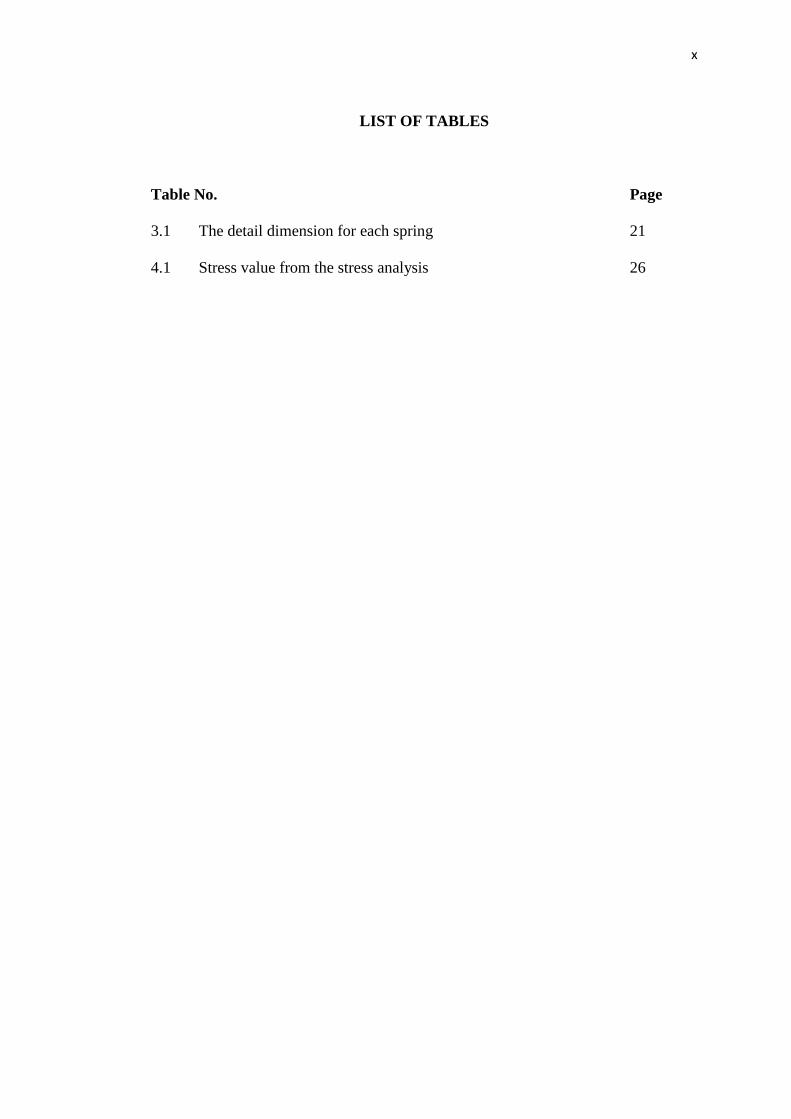
LIST OF TABLES
Table No. Page
3.1 The detail dimension for each spring 21
4.1 Stress value from the stress analysis 26

xi
LIST OF FIGURES
Figures No. Page
2.1 Suspension system 6
3.1 Framework of methodology 14
3.2 Vernier caliper 15
3.3 Teletape 16
3.4 The actual spring picture 16
3.5 Drawing of the actual spring using SolidWorks® 17
3.6 Parameter of the actual spring (variables) 18
3.7 Parameter of the actual spring (constant) 19
3.8 Spring A (actual spring) 20
3.9 Spring B (change the wire diameter, d) 21
3.10 Spring C (change the diameter of the spring, D) 22
3.11 The meshing result for each spring 24
4.1 The stress analysis result for each spring 27
xii
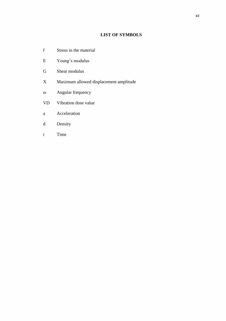
LIST OF SYMBOLS
f Stress in the material
E Young’s modulus
G Shear modulus
X Maximum allowed displacement amplitude
ɷ Angular frequency
VD Vibration dose value
a Acceleration
d Density
t Time
xiii
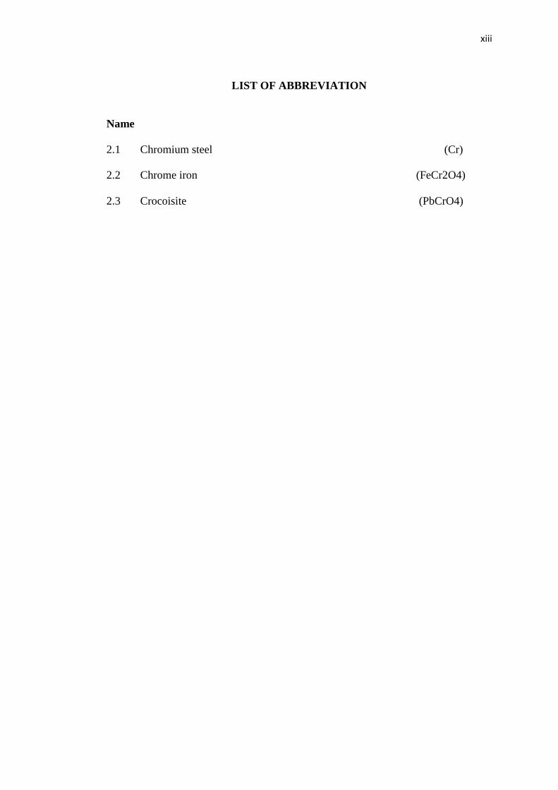
LIST OF ABBREVIATION
Name
2.1 Chromium steel (Cr)
2.2 Chrome iron (FeCr2O4)
2.3 Crocoisite (PbCrO4)
CHAPTER 1
INTRODUCTION
1.1 BACKGROUND
Suspensions, as many other vehicle systems, followed relatively closely the
evolution of the transportation technology. For centuries carts were not equipped
with any sort of suspension at all. Only later, in the eight century, was a primitive
suspension based on an iron chain system developed.
Metal springs were first developed in the 17th
century and shortly afterwards
leaf springs. Various designs were developed until the last century, which saw the
development of the concept of suspension based on a spring and a damper.
Actually what exactly the suspension does at our vehicle? The suspension
determines how smooth or rough the car ride will be. That is the reason why some
vehicles are very smooth and others are bumpy. A good suspension system will let
the car hug corners effortlessly and let the passenger drink without worrying of
making a spill.
So, we need make a few design of spring with different dimension. Besides
that, we still consider the parameter of spring. So that, we able to get the better result
for the dimension spring.

2
In this project, we decide to design a new spring which is we consider
dimension of the spring. Then, we use the software that required to analysis the
spring to gathering data. From that, we will be able to choose the best dimension for
the spring. This is may be used as in the automotive industry in the future plan
maybe. To improve the automobile comfortable and try to fulfill the customer needed
with concern the safety and comfortable for user of vehicle.
1.2 PROBLEM STATEMENT
The problem that we must face are when the car bumping roughly. It will
make the headache that passenger will became worst. When you need to the long
journey when your car through the deep shallow did the water from your drink will
spill out.
Because of these problems, we make a few design of the spring but only
consider about the dimension. Which we consider a few part of the dimension of
spring we need to change. We specific the value of the dimension of the spring we
need to change. The effect of the suspension performance must be related with the
dimension of the spring. To get the good performance of suspension system it must
have a good characteristic of the spring.
1.3 OBJECTIVE
The objective for this project is to identify the effect of the spring dimensions.
1.4 PROJECT SCOPE
What I need to do to get the objective:
1) Model the spring with different dimension using SolidWorks® software.
2) Perform stress analysis using MSC. Nastran/Patran software.

3
1.5 Organization of thesis
This thesis has been written with necessary details to the understanding of
this project. Excluding the introduction, which is the first chapter for this thesis, the
main point of this project is divided into four chapters.
Literature review is the several previous studies on suspension system and the
effect of change it dimension for previous research, Chapter 2. Chapter 3, about the
changed the dimension of spring which is we need to consider about the original
dimension and specific spring of vehicle. Chapter 4 is the results of the analysis are
recorded. Lastly is Chapter 5, it presents the conclusion of overall study and the
future work recommendation.

CHAPTER 2
LITERATURE REVIEW
2.1 INTRODUCTION
The aim of this chapter is to provide all the information of suspension system.
How did the change the dimension of the spring will affect the performance of the
suspension system of our vehicle? What is the good dimension of the spring? The
suspension system will be discussed thoroughly in this chapter. Various sources
including journal, thesis, reference books and literature reviews have been carried out
and revised in writing this chapter.
2.2 SUSPENSION SYSTEM
What is the function of the suspension system? Historically, buses were no
more than special-bodied trucks, sharing the same simple suspension systems and the
priority for low cost of operation. Over the years, passenger demand has required
improvement in chassis and suspension design to deliver improved and consistent
comfort over a wide range of loads, as with cars.
Nowadays, this technology is beginning to transfer to cargo-carrying
vehicles, notably to the semi-trailers. Sometimes, this is driven by particular
customer needs for transport of fragile cargo, but often by legislative requirements,
such as to minimize road damage. Besides that, the suspension system is used to
support a load from above (Donald Bastow, 2004).
The three crucial element of a suspension system are as follows:

5
1. Flexibility, provided by a spring that distorts and recovers (typically
compresses and expands) as the wheel traverses disturbances in the road surface.
2. Damping, which is essential to restrain the body and wheel from resonant
bouncing motions.
3. Location of the wheel or axle.
Figure 2.1 Suspension Systems
Figure 2.1: Vehicle suspension systems contain several elements, with a main
spring supporting the sprung mass and the damper dissipating the energy stored in
the spring during movement. The tire acts as a secondary spring system, acting on
both the unsprung mass of the suspension and the sprung mass of the loaded vehicle
(Donald Bastow, 2004).
Majjad (1997) and Tan and Bradshaw (1997) addressed the problem of the
identification of car suspension parameter. The necessity of trading off among the
6
conflicting requirements of the suspensions in terms of comfort and road holding led
to the use of optimisation techniques.
Besides that, some authors (Chang and Wu, 1997), in order to improve the
comfort, designed a suspension based on a biological, neuromuscular-like control
system.
Whilst road holding and handling can be objectively quantified by the
analysis of the dynamic equation of a vehicle, this is not the case with comfort, as it
is an inherently subjective matter. Ride quality, driving pleasure and driving fun are
concerned with passenger comfort and driver feeling in a moving vehicle.
Vibration transmitted to passenger originates from a host of causes,
including, amongst others, road unevenness, aerodynamic forces and engine and
powertrain induced vibration. Road irregularities are indeed the major source of
vibration. In a comfortable vehicle, vibration must stay within some boundaries. In
order to establish these boundaries, it is firstly necessary to assess and quantify how
to measure comfort. (Emanuele Guglielmino, 2008).
Several criteria have been proposed over the past to assess comfort based on
the nature of the vibration. Some of them are general purpose whilst others are
employed in specialist fields such as off-road and military vehicles (Pollock and
Craighead, 1986).
One first criterion, relevant to the automotive field, is Janeway’s comfort
criterion (SAE Society of Automotive Engineers, 1965). It relates the comfort to
vertical vibration amplitude and permits to find the largest allowed chassis
displacement for each frequency. In essence it states that within the range 1-6 Hz the
maximum allowable amplitude is the one resulting in a peak jerk value of not more
than 12.6 m/s3. In other words, if X is the maximum allowed displacement amplitude
and ɷ the angular frequency, Janeway’s criterion states that:
X ɷ3 = 12.6 (1.1)

7
2.3 VIBRATION
The most general criterion however is the standard ISO 2631 (1978); it is a
general standard applicable not only to vehicles but to all vibrating environments. It
defines the exposure limits for body vibration in the range 1-80Hz, defining limits
for reduced comfort, for decreased proficiency and for preservation of health.
If vibration are applied in all three directions (foot-to-head, side-to-side,
back-to-chest), the corresponding boundaries apply for each component.
Subsequently to the ISO standard and in 1998 Griffin thoroughly reviewed both of
them, analysis merits and their weakest points.
Another criterion proposed is the vibration dose value (Griffin, 1984) which
provides an indication based on the integral of the fourth power of the frequency-
weighted acceleration. The vibration dose (VD) value is calculated as:
VD = ʃ a4dt. (1.2)
Where VD is the vibration dose values and the a is the value of the acceleration for
this equation (Emanuele Guglielmino, 2008).
2.4 COIL SPRING
The use of the coil spring as the primary suspension medium generally
appeared only with the increasing trend toward independent front suspension after
World War. The advantage offered by the coil spring is its almost total lack of
internal friction, and this allows the damping function to be confined to a more
precisely controlled damper unit.
Coil spring, although much more efficient in their ability to store energy and
deflect through large displacements, need to react against member vertically above
their input pads. Also, unlike leaf springs, coil spring do not provide axle or wheel
location and therefore require separate suspension arms.
0

8
Thus, the concept of the coil spring is linked closely to the use of the integral
body 9also termed unitary or monocoque, and that is chassis-less and provides the
structure of the vehicle) or of a complex chassis (that is, one is three dimensional, to
provide a high torsional stiffness that is not achievable with a simple, essentially
two-dimension ladder frame chassis).
The primary function of a suspension system has changed little over the years,
even if the understanding of its behaviour and the quality of its ride comfort have
both made huge advances. A suspension spring is still required to absorb the shock
loadings produced by bumps in the road surface, and it does this by being initially
compressed and subsequently expands on the total mass of the car. The rate at which
it energy is stored depends on the spring rate, or stiffness, and the rate at which it
releases this stored energy is controlled by the natural frequency of the sprung
system, typically in the range 1-1.5 Hz.
Energy storage per unit volume for a leaf spring = f2/ 6E (1.3)
Energy storage per unit volume for a coil spring = f2 / 4G (1.4)
Where f is the stress in the material and for the symbol of E is the young’s
modulus. For the symbol of the G is shear modulus from second equation (Donald
Bastow, 2004).
Today, most (but not all) suspension designs employ coil spring in a variety
of forms, typically used concentrically with telescopic damper struts (often referred
to as coil-over-damper).
The flexibility of their design criteria and their ability to be manufactured
relatively cheaply, in large quantities and with consistent characteristics, has brought
coil spring to the forefront of modern suspension design. In the modern, highly
optimized body shell, they also feed road loads into well-spaced and stiff areas of the
engineering structure (Donald Bastow, 2004).
9
2.5 CHROMIUM STEEL
A lustrous, hard, steel-gray metallic element, resistant to tarnish and corrosion
and found primarily in chromites. It is used in the hardening of steel alloys and the
production of stainless steels, in corrosion-resistant decorative plating, and as a
pigment in glass. Chromium does not tarnish in air, when heated it born and forms
the green chromic oxide. The Atomic Number of this element is 24 and the Element
Symbol is Cr.
Chromium steel (Cr) (2.1)
Elements can be classified based on their physical states (States of Matter) e.g.
gas, solid or liquid. This element is a solid. Chromium is classified as a "Transition
Metal" which is located in Groups 3 - 12 of the Periodic Table. Elements classified
as Transition Metals are generally described as ductile, malleable, and able to
conduct electricity and heat. Nearly 75% of all the elements in the Periodic Table are
classified as metals which are detailed in the List.
Occurrence of Chromium the ore from which all chromium compounds are
made is chromites, or chrome iron ore (FeCr2O4). The element also occurs in small
quantities in many other minerals, especially in crocoisite (PbCrO4), in which
mineral it was first discovered.
Chrome iron (FeCr2O4) (2.2)
Crocoisite (PbCrO4) (2.3)
Chromium, like manganese, is very hard to reduce from its ores, owing to its
great affinity for Oxygen. It can, however, be made by the same methods which have
proved successful with manganese. Considerable quantities of an alloy of chromium
with iron, called ferrochromium, are now produced for the steel industry.
Properties of Chromium are a very hard metal of about the same density as
iron. It is one of the most infusible of the metals, requiring a temperature little short

10
of 3000° for fusion. At ordinary temperatures air has little action on it; at higher
temperatures, however, it burns brilliantly (Lange’s Handbook of Chemistry (1952).

CHAPTER 3
METHODOLOGY
3.1 INTRODUCTION
This chapter will describe further on the experiment which is design the new
dimension of the spring, test the dimension spring and analysis the suspension
system performance. In order to complete the experiment, methodology is one of the
importance things that need to be considered. The objective of the methodology is to
make sure that the project is running on schedule and the data obtained from the
experiment can later be analysed.
In this chapter, all the details and related discussion on the process and
methods that involved in the project are described. The process and timeline of the
project is illustrated using flow chart and Gantt chart. Both charts are fundamental
for this project as both charts explained every step to achieve the objective of the
project. The project start with working on literature review and the end by submitting
the complete report to the faculty after make a correction.
3.2 PROJECT FLOWCHART
Figure 3.1 shows the flow chart of every process that needed to complete the
project. In the beginning, the project starts with understanding the title, determining
the project scope and general background of the project.
Then, the literature review of the project is being made. All the sources for
the information of the literature review came from the books, journal and from the

12
internet. Besides that, the data and information from the previous research can be
used to gain new idea and concept to be used in the project. The information for the
project is more cleared and understood better after done literature review process.
After that the computer modelling for the new model of the spring is needed.
Firstly, we design the new dimension of the spring using software SolidWorks®.
After that, we want to analysis the spring after we give the force on the each spring
we use the MSC. Nastran/Patran software.
The stress analysis was carried out to analysis of stress of the spring. The
highest amount of stress the spring can withstand the hardest spring. This process
will do for each type of spring. So, we can make the comparison of stress result for
each spring with different dimension.
The result from the analysis was discussed. If the stress value from the testing
did not satisfy the objective and scope of the project, the testing is repeated to get the
desired results. After the objective and scope of the project were fulfilled, the next
step of the project is to present the Final Year Project to the panels. Final step of the
project is to compile and submit the complete report of the project to faculty.

13
Figure 3.1: Framework of methodology.
FYP 1
FYP 2

14
3.3 MEASUREMENT TOOL
This is the measurement tool that we used to measure the dimension of the
original value of the spring at the automotive laboratory of Universiti Malaysia
Pahang. The dimension we used the manual reading as shown in the picture below.
Figure 3.2:Vernier caliper –has a movable scale that is parallel to a fixed scale
Figure 3.3: Teletape-has adjustable tape that can use depend on the scale of
workpiece.
15
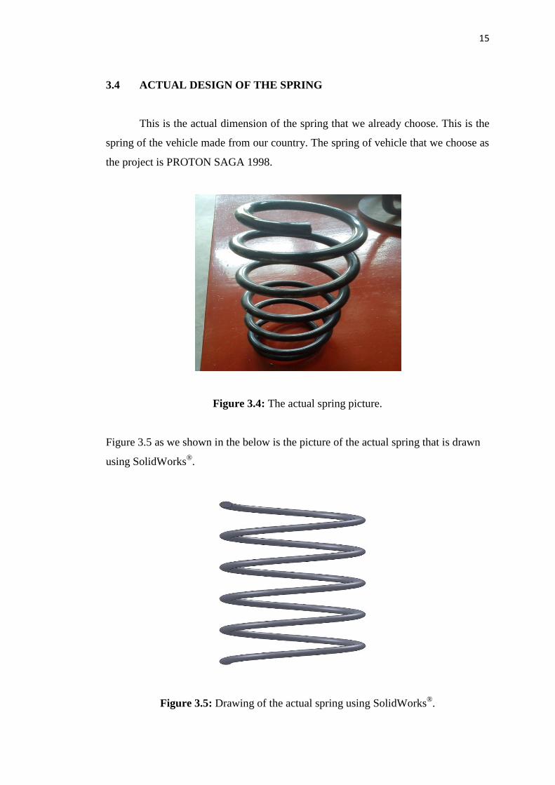
3.4 ACTUAL DESIGN OF THE SPRING
This is the actual dimension of the spring that we already choose. This is the
spring of the vehicle made from our country. The spring of vehicle that we choose as
the project is PROTON SAGA 1998.
Figure 3.4: The actual spring picture.
Figure 3.5 as we shown in the below is the picture of the actual spring that is drawn
using SolidWorks®.
Figure 3.5: Drawing of the actual spring using SolidWorks®.

16
3.5 PARAMETER OF THE SPRING
The parameter of the spring such as force, types of material, mechanical
properties is needed this is because to prevent for any mistake or to avoid the
regardless during make the analysis of project. These parameters were used as the
input for the stress analysis that we need to do into our project.
3.5.1 Variable
(a)
(b)
D=14.02cm
l1 = 6.37 cm

17
(c)
Figure 3.6: The dimensions and images for the actual spring a) spring diameter, D,
b) spring pitch, l1, and c) wire diameter, d.
3.5.2 Constant
All the parameter, such as the types of the material we used for the spring, the
total length of the spring, and the mechanical properties is the important thing in our
project. To get the good result, we must constant the force to require the valid stress
result from the stress analysis.
d = 1.22cm

18
Figure 3.7: This is the dimension and the images for the actual spring and all the
parameter that we need to consider before and during this project.
Force
L=30.01cm
Types of material

19
3.6 DESIGN OF THE DIFFERENT DIMENSION OF THE SPRING
3.6.1 First design
This is the original of the spring that we do not modify the dimension of the
coil spring. This dimension of the spring we assume as the spring A as shown in
Figure 3.5.
Figure 3.8: Spring A (actual spring).

20
3.6.2 Second design
This is the second of the spring that we modified the dimension of small
diameter of the coil spring. This dimension of the spring we assume as the spring B
as shown in Figure c.
Figure 3.9: Spring B (change the wire diameter, d).

21
3.6.3 Third design
This is the third of the spring that we modified the dimension of large
diameter of the coil spring. This dimension of the spring we assume as the spring C
as shown in Figure a.
Figure 3.10: Spring C (change the diameter of the spring, D).
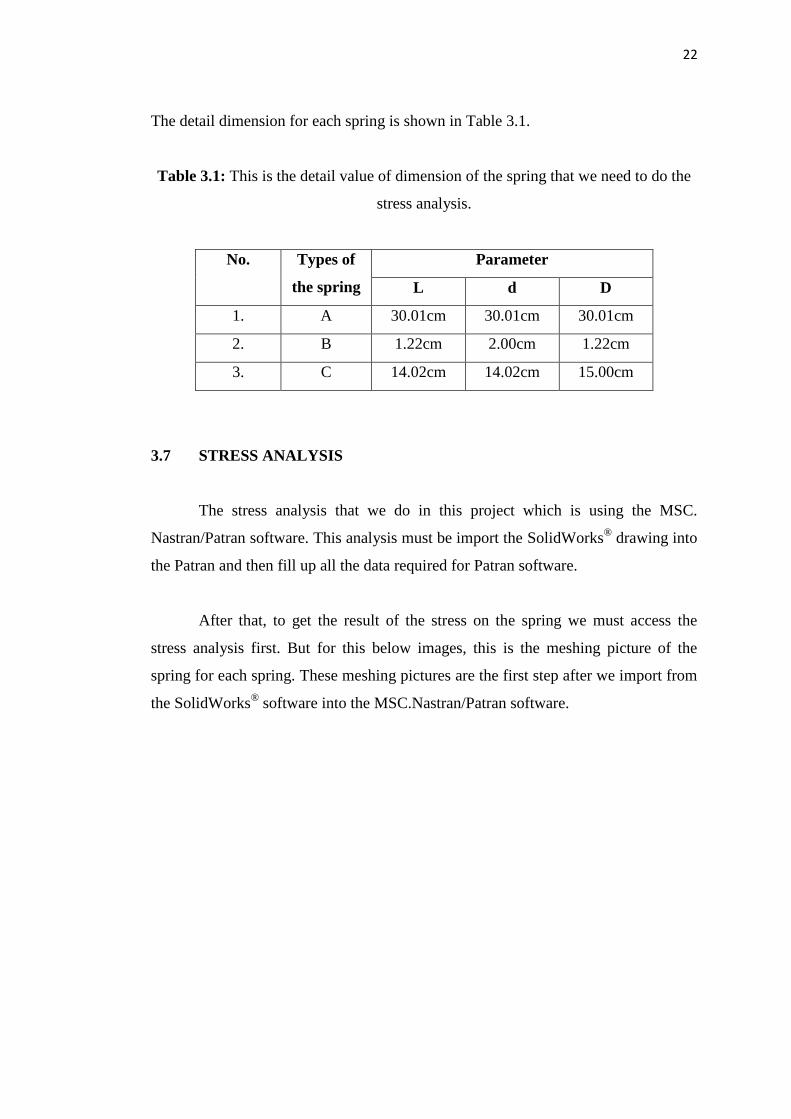
22
The detail dimension for each spring is shown in Table 3.1.
Table 3.1: This is the detail value of dimension of the spring that we need to do the
stress analysis.
No. Types of
the spring
Parameter
L d D
1. A 30.01cm 30.01cm 30.01cm
2. B 1.22cm 2.00cm 1.22cm
3. C 14.02cm 14.02cm 15.00cm
3.7 STRESS ANALYSIS
The stress analysis that we do in this project which is using the MSC.
Nastran/Patran software. This analysis must be import the SolidWorks® drawing into
the Patran and then fill up all the data required for Patran software.
After that, to get the result of the stress on the spring we must access the
stress analysis first. But for this below images, this is the meshing picture of the
spring for each spring. These meshing pictures are the first step after we import from
the SolidWorks® software into the MSC.Nastran/Patran software.

23
(A) Original design
(B) Second design
(C) Third design
Figure 3.11: The meshing result for the a) spring A, b) spring B, and c) spring C.

CHAPTER 4
RESULTS AND DISCUSSION
4.1 INTRODUCTION
This chapter present result of this project and later on, the results are
discussed in details. In this project, the result obtained by using experimental method
which is analyzing the effect of the dimension spring to the suspension system by the
stress sensor. The recommendation for this project will be discussed in the next
chapter.
4.2 STRESS ANALYSIS RESULTS
All the data is importance to get the comparison between the springs. When
the stress applied to the spring, we can get the result of the amount of stress on the
spring. We used MSC. Nastran/Patran software, to get the stress result. The types of
the spring and the diameter of the spring we can get from the previous table, (Table
3.1).