Correlation Dimension for Pressure Fluctuation in Hydraulic Turbine ...

i.
ENGINEERING MONOGRAPHS No. 30
United States Department of the Interior
BUREAU OF RECLAMATION
STRESS ANALYSIS
OF HYDRAULIC TURBINE PARTS
by F. 0. Ruud
< :. 1 ! ; ,L ‘$ p; ;+
I ^ p) enver, Colorado
’ $uly 1962 i 75 cents
United States Department of the Interior
Bureau of Reclamation
Engineering Monogra.phs
No. 30
Stress Analysis
of Hydraulic Turbine Parts
by F. 0. Ruud Engineer, Applied Mathematics and Mechanics Section
Technical Engineering Analysis Branch Commissioner’s Office, Denver, Colorado
Technical Information Branch Denver Federal Center
Denver, Colorado
CONTENTS
PREFACE ..............................................................
SPIRAL CASE .......................................................... Shell ................................................................. Flange Joints ...................................... ................... Manholes .......................................... ................... Man Door ............................................................
STAY RING ............................................................ Ring and Vanes ....................................................... Bolted Joints ..................... ; ...................................
HEAD COVER .......................................................... Head Cover .......................................................... Attachment to Stay Ring ............................................... Radial Joints .........................................................
GATE MECHANISM ...................................................... Servomotors .......................................................... Gate Operating Ring ................................................... Wicket Gate Linkage ................................................... Wicket Gates .........................................................
SPIRAL CASE SUPPORTING STRUCTURE ................................. Jack Loads ........................................................... Tiedown Bars ......................................................... Jack Pads and Tiedown Lugs ........................................... Support Columns ......................................................
TURBINE RUNNER AND SHAFT .......................................... Turbine Runner or Pump Impeller ...................................... Turbine Shaft .........................................................
GUIDE BEARING SUPPORT BRACKET ....................................
PIT-LINER ............................................................. Collapsing Stability ................................................... Superimposed Loads .................................................. ServomotorSupports ...................................................
DRAFT TUBE LINER .................................................... Collapsing Stability .................................................... Anchorage ........................................................... Pier Nose ........................................................... Manhole and Man Door ................................................
MISCELLANEOUS ITEMS ................................................ Test Bulkheads ....................................................... Bottom Ring ..........................................................
LIST OF REFERENCES . . . . . . . . . . . . . . . . . . . . . . . . . . . . . . . . . . . . . . . . . . . . ...*. 31
Page
1
6 6 9
10 10 11 12
12 13 14 14 16
17 17 17 I 17 18
18 18 19
22
23 23 23 24
24 25 26 27 27
27 27 29
i

LIST OF FIGURES
Frontispiece I Sectional Elevation of Francis Turbine . . . . . . . . . . . . . . . . . . . . . . .
Frontispiece II Sectional Elevation of Kaplan Turbine . . . . . . . . . . . . . . , . . . . . . . . .
Number
1.
2.
3.
4.
5.
6.
7.
8.
9.
10.
11.
12.
13.
14.
15.
16.
17.
18.
19.
20.
21.
22.
23.
24.
25.
26.
27.
Circular Torus .................................................
Elliptical Torus .................................................
Idealization of Man Door Cutout ...................................
Stress Concentration Factors at Manhole .....................................................
Two Types of Manhole Reinforcement ..............................
Reinforcing Around Rectangular Manhole ...........................
Stay Vane Cross Section ..........................................
Stay Ring Cross Section ..........................................
Forces on Stay Ring Bolted Joint ..................................
Section of Head Cover ............................................
Transformed Cross Section of Head Cover .....................................................
Servomotor Linkage .............................................
Forces on Gate Operating Ring ....................................
Functions of Moment, Shear. and Tension for Ring Solution Shown in Figure 13 .............................................
Moments in an Operating Ring .....................................
Gate Linkage Mechanism .........................................
Typical Wicket Gate Linkage System ...............................
Wicket Gate Loads ...............................................
Uplift Forces on a Francis Turbine ................................
Uplift Forces on a Propeller Turbine ..............................
Idealized Shaft Arrangement ......................................
Deflections of Shaft from Inertia Loads ..................................................
Unit Load Deflections of Shaft .....................................
Typical Guide Bearing Bracket ....................................
Guide Bearing Bracket ...........................................
Servomotor Thrust Plate Loading .......................................................
Draft Tube Liner ................................................
Page
iv
V
4
5
5
6
8
9
10
12
13
14
15
15
16
16
17
19
19
20
21
21
22
23
24
25
ii

LIST OF FIGURES- -Continued
Number Page
28. Cast Pier Nose .................................................. 27
29. Welded Pier Nose ............................................... 27
30. Test Ring ...................................................... 28 .
LIST OF TABLES
1. Shell Stresses in the Spiral Case .................................. 2
2. Flange Stresses in the Spiral Case ................................. 3
3. Tabulation of *(Ax) ............................................. 6
4. Stay Ring Stress Computation ..................................... 7
5. Head Cover Section Properties .................................... 11
6. Computation for Critical Speed ..................................... 20
. . . 111

FROImIsPIPzEl - Sectional elevation of Franc18 Turbine.
iv
_-.. .

Blrle swoaotnr --
Wick
Y I I
I II
11 ,,.Sisr ring
FRONTISPIECE 2 -Sectional elevation of Kaplan turbine.
V

PREFACE ity theory solutions, stress concentration allowances, or plastic analyses.
It would be virtually impossible in de- veloping general procedures such as these to provide for all the possible variations which a turbine designer could introduce into his design. Therefore, use of these proposed methods must be based on sound engineering judgment.
T* his monograph presents procedures for stress analysis of parts for reaction tur- bines. Many procedures presented herein are also applicable to impulse turbine de- signs. The procedures have been prepared to assist the engineer with his studies in determining whether aturbine design meets the structural requirements of Bureau of Reclamation Specifications. The methods given are based mainly on mechanics, the- oryof structures, and strength of materi- als. They do not include complete elastic-
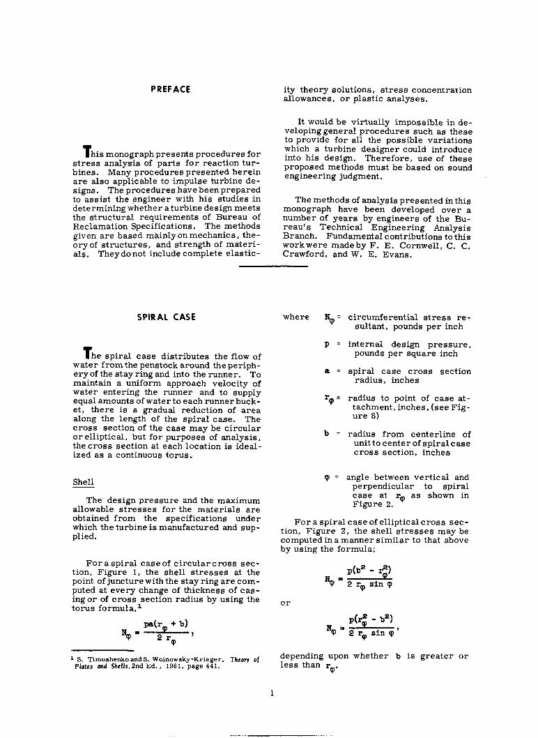
SPIRAL CASE
T he spiral case distributes the flow of water from the penstock around the periph- ery of the stay ring and into the runner. To maintain a uniform approach velocity of water entering the runner and to supply equal amounts of waterto each runner buck- et, there is a gradual reduction of area along the length of the spiral case. The cross section of the case may be circular or elliptical, but for purposes of analysis, the cross section at each location is ideal- ized as a continuous torus.,
Shell
The methods of analysis presented in this monograph have been developed over a number of years by engineers of the Bu- reau’s Technical Engineering Analysis Branch. Fundamental contributions to this workwere made by F. E. Cornwell. C. C. Crawford, and W. E. Evans.
The design pressure and the maximum allowable stresses for the materials are obtained from the specifications under which the turbine is manufactured and sup- plied.
For a spiral case of circular cross sec- tion, Figure 1, the shell stresses at the point of juncture with the stay ring are com- puted at every change of thickness of cas- ing or of cross section radius by using the torus formula, l
L S. Timoshenko and S. Woinowsky-Krieger, Theory of Plates and Shells, 2nd Ed. , 1961, page 441.
where Ng = circumferential stress re- sultant, pounds per inch
P = internal design pressure, pounds per square inch
a = spiral case cross section radius, inches
r,+, = radius to point of case at- tachment, inches, (see Fig- ure 8)
b = radius from centerline of unit to center of spiral case cross section, inches
p = angle between vertical and perpendicular to spiral case at rep as shown in Figure 2.
For a spiral case of elliptical cross sec- tion, Figure 2, the shell stresses may be computed in a manner similar to that above by using the formula:
N = pb* - $1
Cp 2 rp sin cp
or
N = P(I$ - b2)
Cp 2 rq sin cp '
depending upon whether b is greater or less than r
cp’
1

TABLE1 - Shell. stresses in the spiral case
Note: Make allowance for net area on riveted casings and for joint efficiency factors on welded casings.2
The terms are as defined above and in
Figure 2. 32 The shell stress is u = t ,
where t = shell thickness in inches.
Table 1 is used in evaluating the stresses at many points around the spiral case.
Flange Joints
A procedure has been developed for ana- lyzing this type of flange. ss4 When several flanges are to be analyzed, which is nor- mally the case, the use of a table will save time and reduce the chance for error. Ta- ble 2 and the accompanying figure and no- tations that define the terms used are rec- ommended.
Items to be checked on the spiral case flanges include the following:
a. Radial bending stress in the flange ring.
b. Stress at juncture of hub and flange; this stress is the sum of the bending or discontinuity stress and the direct tension stress due to end pull.
c. Length of hub, if a hub is re- quired, should be approximately equal
(Item 28 on Table 2).
FIGUREll- Circular Torus.
FIGURE 2 - Elliptical Torus.
The flange bolts should be prestressed to not more than twice the working stress or one-half the yield point stress.
Manholes
Manholes in spiral cases are of varying design, but generally are either elliptical or rectangular. Theymay be cast or fab- ricated from plate steel sections, and are usually so designed that the normal pres- sure loading acts to close the man door.
Analytic solutions of the problem of a reinforcedcircular hole in a flat plate un- der uniform tension have been prepared.sP
d. Tension stress in bolts.
Normally, the flanges on the casing are designed for bearing outside the bolt circle.
2 Rules for Construction of Unfired Pressure Vessels, Section VIII, ASME Boiler and Pressure Vessel Code, 1959.
3 F. E. Cornwell, Miscellaneous Notes on the General Problem of Flonac Dcsian. -
4 S. Timoshenko, Strength of Materials, Part II, 3rd Ed. , 1956. page 141.
s S. Timoshenko and J. N. Goodier, Theory of Elasticity, 2nd Ed., 1951, pages 78-85.
0 S. Timoshenko, Strength of Moteriols, Part II, 3rd Ed. , 1956, page 305.
2

j L ____ --------q,J
I p --------- ------XJ!atj
I I I I I I I I I I I 1 ,
3

FIGURE 3 - Idealization of manhole cutout.
However, the practical procedure in the analysis of an actual manhole design is nec- essarily approximate.
Although the membrane forces applied to the man door frame by the shell are well defined, the presence of the opening and its reinforcement causes concentration of stresses. For a circular hole without re- inforcement in a flat plate loaded by ten- sion in one direction, the stress concentra- tion factor is 3; for a very rigid circular inclusion the stress concentration factor is 1. 5. In addition, the radial loads applied by the man door cause bending stresses in the frame and the surrounding shell. We may conclude that stress concentrations, dis- continuity stresses, and bending stresses are always present to some degree. The ultimate test of the design must then be in pressure-proof load.
The following approximate methods may be used as a basis for analysis of man door openings.
The tensile stresses at the manhole, which is normally reinforced, can be de- termined byreferringto Figures 3 and 4.e
where A = cross-sectional area of the opening
Al = cross-sectional area of the reinforcing material
An approximation, which is true only on the vertical centerline of the spiral case, is to assume the longitudinal tensile stress is one-half the circumferential tensile stress. This wouldmean that the stress concentra- tion at the edge of the hole instead of being 3 for stress in only one direction would be (3.0 - 0. 5) = 2. 5, whentensionsintwomu- tually perpendicular directions are consid- ered and the value of one stress is one-half the other.7
Let
Q = circumferential tension stress without a hole in the casing in pounds per square inch
a- = the maximum circumferential stress at the edge of the hole in pounds per square inch
%3X Then, Figure 4 gives - Al versus - . Note that values on the curdle apply to str%ss in one direction only. A correction to cm thus obtained can be made for a longitudi- nal stress of !$ = P 0.833.
by multiplying cmsx by
3*0 The stress concentration factors above
may be used for circular, elliptical (Fig- ure 5), and rectangular (Figure 6) man door 0penings.e Although the major por- tion of the reinforcing material should be
‘3. ‘rimoshenko, StrcngU~ of Materials, pas R, page 306.
a Rules for Construction of Unfired Pressure Vessels. Section VIII, ASMEBoiler andPressureVesse1 Code, 1959, Paragraph UG-37.
2.0
amax. Q
0 0 0.5 Al 1.0 1.5
A
FIGURF: 4 - Stress concentration factors at manhole.
4

at the edge of the opening, some plate re- inforcement should be provided around the man door frame to (a) act as a transition between the shell and the man door frame, and (b) to aid in resisting bending of the shell caused by radially directed forces from pressure load on the man door. 410 See References (17) and (18).
Occasionally the methods of Hetenyi” may beapplied to the analysis of the rein- forcingplates. When a shear of V pounds per inch is applied to the edge of the spiral casing shell by radial loads on the man door frame, the moment in the shell is
M = 5 emhx (cos Xx - sin Xx) l2
inch-pounds per inch,
or
M- & @(hx) ,
II 1
FIGURE 6 - Reinforcing around a rectangular manhole.
where A =
Fabricated
thickness of the reinforcing plate should
(for steel) decrease linearlyto zero at sdistance from the edge of the shell of pi; inches (the first point of zero moment), which is
I ,,-Cast section usually adopted as the limit of the rein- forcing plates around the opening. The maximum moment which must be carried
this location is approx- which is usually accept-
able to the shell. The resistance of the man door frame
x‘-Spirol case--d”’ to the loads applied by the man door should be investigated. Usuallythe frame is rath- er rigid and simply transmits these loads
FIGURE 5 - TWO types of manhole reinforce- through the adjacent plates to the surround- ment. ing shell as radial shear forces.
X = distance fromedge of shell, The rectangular man door opening shown inches in Figure 6 should beprovidedwith gener-
ous radii at the corners of the opening to re- a = spiral case cross section duce the effects of stress concentration at
radius, inches these points.
t = thickness of spiral casing, inches. Man Door
Tabulations of q(h) are given in Table 3. The man door can be treated as a flat plate reinforced by ribs and subjected to
The combined thickness of the plate and uniform load from the internal pressure
shell are required to carry the moment in the casing. Consider the edges as sim- V at the edge of the manhole frame. The ply supported. 5x
S Mervin B. Hogan, A Suwey of Literature Pertaining to Stress Distribution in the Vwnity of a Hole and the Design of Pressure Vessels, 1950.
10 H. Boyd Phillips and Ira E. Allen, Stresses Around Rectangular Openings in a Platc.1960.
11 M. Hetenyi, Beams on Elasuc Foundation, 1946. 12 Other formulas for deflection, rotation, and shear
of the shell may be found in References (1) and (10).
Anexampleof asolution for this type of loading is Roark’s Case No. 36.13 Other solutions are also available.14 It is noted
13 Raymond J. Roark, Formulas for Stress and Strclln, 3rd 1954, page 203.
IF”,: ‘Timoshenko and S. Woinowsky-Krieger,Themv of Plates and Shclls.Znd Ed. , 1961, page 441.
--------

1.6 1 -0.21 1
TABU 3 - Tabulation of $(AX)
r
2.8 1 -0.08 1
3.0 1 -0.05 1
5.0 1 0.008 1
that the stresses are &iven for a flat plate. Since the man door is normally a built-up section, it is desirable to determine the moment on the section and consequently the stress. Equating 6~
P to the expres-
sion for stress will give the desired dis- tributed moment, which, when multiplied by the width of the door, maybeused in the conventional bending formula to give ap- proximate conservative results.
The tension stress on the root area of the tiedown bolts for the door should also be determined, if applicable, and compared
to the allowable design stress for the bolt material.
STAY RING
T he stay ring provides structural con- tinuity between the upper and lower por- tions of the spiral case, as well as pro- viding passage and guidance for the flow of water to the turbine runner.
Center of gravib of vane--
FIGURE 7 - Stay vane cross section.
Ring and Vanes
In the analysis of the stay ring, the procedure given by Evans is followed.15 Messrs. Bovet can be consulted for addi- tional information.9l7
The moment of inertia of the stay vane cross-sectional area is computed about a tangential axis through its centroid (axis T-Tin Figure 71, and the moment of iner- tia of the stay ring cross-sectional area is computed about a horizontal radial axis throughits centroid (axis R-R in Figure 8).
The forces applied to the stay ring are the membrane load of the torus, the pres- sure on the face of the ring, and the head cover load. Cognizance should be taken of the radial location of load application, as well as the conditions of operation; see Figures 7 and 8 and Table 4.
1s W. E. Evans, ‘Stress 4nalysis of a Hydraulic Turbine Stay Ring, 1954.
lo G. and Th. Bovet,Contribution to the St;ess 4nalysis of a Tubular Scroll, 1945.
1TTh. Bovet, Calculation ofthe Mechanical Strengqh of Spiral Casing for High Head Turbines, 1958.
6

TABIS 4 - Stay ring etrarr oomputatlon
I 7” ” A” I
49 MRC = M,, + M,, + M,, + M,, + Mes+
22 1 PO = ro - ‘/e sin 8, (radius to centerline of shell attachment, inches) 23 1 c” (radial distance from vane centroid to extreme tension fiber, inches)
-TV ” A” P 54 Id,,= MRi+MRp+MR3+MR4
_ cc u - MRT2BR"(I-A) 24 AR (area of ring cross-section, inches’) 25 A, (Oreo of stay vane cross-section, inches’) 26 k (moment of inertia of rmg area about axis RR, inches’) 27 I, (moment of inertia of “one area about axis TT, inches’) 26 t (thickness of spiral case shell, inches)
(P + b) 29 N+= pa.-&
(SpirOl,COSe CirCu?ferential stress resultant, pounds
+ per Inch, at rodw r+)
30 N” = N$sin b’* (vertical component of Nb) 31 NH = N#cosBp (horizontot component of N+)
.,., YT- n
56 ,Jb” = MVTC, i IT P
57 a Total = aTv + ab”
RING I 56 A IA,,= MS, I
59 .X H = NH2 - PH (use maximum value of EH) I I
” 1 1
rti R” 60 ,?V= N”~-+(P”+PC&- 0 Ra
63 OTR= Y
62 MSRRv
AR
I XHR
33 P” =$lYs.Y,
(ro’-R ‘) pA”n (vertical pressure load on ping element,
pounds per inch, ot radius R”)
32 P” = p.L-- 2R” ”
”
pounds per inch, at radius A”)
_ (r.+R,) (horirantol pressure load on ring element.
1 -c 1 n _ - (R;- Reel (headcover lood,gotes closed, pounds per inch at I IL,. BOLTED J(
I L1 1 .I n I64 1 abr= MS-,‘“SR”” y,
I
1 ‘R 65 I a Total = ab, + oTR
I
IINTS 66 AF (area of flange face) 67 YF (vertical location of face centroid) 66 Ab (are0 of bolts) 69 Yb (Vertical location of bolts’ centroid)
34 p Cl
= P(Rc~-R,,~) +O.~PU$,~-R;) + ‘7($-R,*) (~o~~~~p~~~u~ds per inch ai A”) 2Rv
9 *
53 I& = v”- 2Rv radius R”)
3 36 M,,= Nv(r+-R,) ?i;
I 70 I IF (moment of inertia of flange face area) [ 71 T=THR” 72 ($-Yr) 73 tyb-yF) 74 ,,=TA + T(YvYr)*&Yb-YF)+MsRR,
AF IF y
F s0
ed preload of bolts) I-I . MS, *R” I, L (port of total twisting moment
= R..R,I, n + nR.. I. L carried by ring)
37 MR2=Nn(Yr-Y+) ;
36 MR3= P, (Y” -Y,) 39 M,,= P” (RH -R”) 40 MRs-, = PC, (Rd-R”) 41 MM-2 = P,,(Rd-R,)
/’

Since the radial forces on the stay ring are resisted by tension in the ring, and the vertical forces are resisted by tension in the vanes, the total applied twisting moment % is found by summation of moments of the radial forces about a kngential axis throughthe ring centroid and the moments of the vertical forces about a tangential axis through the centroid of the vane. I+ is then
divided between the ring and the vane in proportion to their relative stiffnesses, as follows:
where 7?
is the twisting moment on the ring, inc -pounds per inch at Rv, and
s, = radius to centroid inches
IR = moment of inertia inches +
of vane,
of ring,
L I height of vane at centroid, inches
Then
where Mv is bending moment on the stay vane in inch-pounds.
Stresses in the ring and the vane may then be computed as follows:
CH% $+“sR%y r-+ Qw4 + IR
r> pounds
per square inch
where
AR = cross-sectional area of stay ring, square inches
M, = bending moment in a vertical plane of stay ring at the support, inch-pounds
Yr - vertical location of ring cen- troid, inches
CR = sum of horizontal forces act- ing on stay ring (pounds per inch at Rv ), pounds per inch
Rs P radius to centroid of ring, and inches
M,
LJ = moment of inertia of vane, inches 4
n = number of vanes (assume equally spaced).
FIGURE 8 - Stay ring cross section.
using
cv = Rv2+(Pv+P ,s c2 %'
pounds per inch at R+
Also, cv2Jcst Ml,
%7%ne= nA, - + ri cvI pounds per
square inch,
where
cv - sum of vertical forces act- ing on stay vane (load per inch at ~1, pounds per inch
Ib = cross-sectional area of stay vane, square inches
IT a moment of inertia of vane area about a tangential axis through centroid, inches4
8

cv = radial distance from vane centroid to extreme ten- sion fiber, inches.
Table 4 is recommended for use in com- puting the stresses.
An approximate check computation for the stay vane stresses may be obtained with the following formula:
b-a-R, A, 1
where
P - spiral case internal pres- sure, pounds per square inch
a = spiral casing radius, inches
b - radius to torus centerline, inches
a= moment of inertia of stay vane about tangential axis through center of gravi- ty, inche&, (seeFigure 7).
This formula applies the torus shell stress resultant to the stay vanes eccen- trically, at the horizontal centerline of the spiral case.
Bolted Joints
Bolted joints occur in nearly all stay rings and must be designed to resist the most severe conditions of loading which may be applied.
The following comments generally apply to all stay ring bolted joints:
a. The bolts should be prestressed tonot more thantwice the maximum ap- plied working stress, or 50 percent of the yield point stress.
b. The thickness of the flanges should be at least l-1/2 times the maximum bolt diameter.
c. The -externally applied loading should combine the effects of eccentric- ally applied tension and moment at the location of the bolted joint.ls
l*T. f. Dolan, and J. H. McClow,The Influence of Bolt Tension and Eccentric Loads on the Behwior ofa B&d loint, 1950.
d. The requiredpreload of the bolts on the joint face (bolt stress multiplied by bolt area) must prevent the joint from opening under any condition of applied loading.
At point ‘0’ of Figure 9, the joint must not open. faces,
Therefore, assuming rigid flange
+ T(YF-YJ + B(Yb-Ypl) + bfa R,
IF 4
where
AF = area of flange face, square inches
IF = moment of inertia of flange face area about a horizontal centroidal axis, inches*
YF I distance from bottom edge of stay ring to centroidal axis, inches
‘b - distance from bottom edge of stay ring to centroid of bolt pattern, inches
yr = distance from bottom edge of stay ring to centerline of application of tensile load, inches
B = total bolt force, pounds
T - total tensile force, pounds
MsR R, = totalapplied moment, inch- pounds.
The use of Table 4 will facilitate the computing process.
FIGUFE 9 - Forces on stay ring bolted joint.

HEAD COVER
T he head cover is used to seal off the region above the turbine runner and to di- rect the flow down through the runner. It is bolted to the stay ring. Usually, the lower main shaft guide bearing and pack- ing box are supported on the head cover. There is a watertight seal betweenthe head cover and the stay ring, and there is a wear - ing ring between the head cover and the runner .
Unless the head cover load is specified, it will be assumed that design pressure acts on the annular area of the head cover between the stay ring seal and the wearing ring.
Figure 10 shows a cross -sectionalview of a head cover. The sections shown are only those which are continuous around the circumference of the cover.
Head Cover
To compute tangential stresses in the head cover, it is analyzed as a circular ring whose width is not small compared to its radius, subjected to twisting moments dis - tributed along its centerline 1s
The tangential stress at the location y, r (see Figure lo), is given by:
L = pJr($ -IQ
where
u = the tangential stress, pounds per square inch
M = the total bending moment on any radial cross section of the head cover, inch- pounds
ls S. Timosheao, Strcnqth of Materials, Part II, 3rd Ed. , 1956, page 140.’
c ,4enter line of head cow ,/’
.,,-tcntroidol
--- ----.____-._.___._ p ___-..___________ __._ 4
I--- Wotsr-tight ml-*”
; -----------.-_ _ _____. Rc ______._________.________
FIGURE 10 - Section of head cwer.
Y = the distance from the hori- zontal centroidal axis of the head cover cross sec- tion, inches (positive when measured upward)
F = the distance from the center of the head cover to the point under consideration, inches
L = the total hydrostatic load on the head cover, pounds
% = the radius of the head cover holddown bolt circle, inch - es
RC = the radius to the head cover stay ring seal, inches
% = the radius to the runner seal inches
P = the hydrostatic pressure, pounds per square inch
Integration of the expression J
2 drdy is effected by dividing the cross:section shown in Figure 10 into a suitable number of elemental areas. The following expres - sion gives the contribution of the individual element to the moment of inertia of the sec- tion:
where
A = the area of the element, square inches
.O

S = the length of a rectangular element in the r-direction, inches
t = the length of a rectangular element in the y-direction, inches where
The bolt stress is given by:
Ub = -&
The summationas shown in Table 5 will give a good approximation to the value of the double integral,
The maximum tangential stress in the head cover can be computed from the ex- pression previously stated.
U= & r
ss $rdy
using the location in the cross section where the ratio y/r is maximum. This locationis usually at the inside edge of the head cover and may be at the top or bottom.
Attachment to Stay Ring
The head cover is usually attached to the stay ring by bolts through a flange at the outer edge of the cover. To check this con- nection, two computations will usually suf- fice. Thetensile stresses should be com- puted at the root areas of the bolts; also, the bending stresses should be computed in the flange, acting as a cantilever beam.
‘b P the bolt stress, pounds per square inch
n = the total number of bolts holding the head cover to the stay ring
Ab = thenet area of one bolt at the thread root, square inches
L = the total hydrostatic load on the head cover, pounds.
The bending stress in the holddown flange is given by:
where
6 P the bending stress in the holddown flange, pounds per square inch
P = the hydrostatic pressure, pounds per square inch
e, %, s-2 Pa, and h are dimen- sions in inches as shown in Fig- ure 10.
The above bolt stress and the bending stress in the holddown flange are based on
!l%Bm5 - Head cover section properties
an assumed direct bolt pull with no flange action. This condition is considered un- conservative for the bolt stress and overly conservative for the flange bending stress. An assumed complete restraint (against ro- tation) at the bolt circle would reduce the flange bending stress to one-half the value computed above. The increased bolt pull or stress with flange action can be obtained by multiplying the stress computed above by the lever arm ratio:
flange O.D. - R + e . fhnge O.D. - 2%
The actual flange and bolt stresses are probably between the two extremes com- puted above, but somewhat nearer to the latter case.
In addition to the bolting there is a dowel requirement between the head cover and stay ring. If the operating ring is guided by the bearing support bracket, it is smaller in diameter thanthe wicket gate circle. For this case, if one of the servomotor pistons is against its stop, a horizontal thrust of double the thrust of the individual servo- motor is applied to the bearing bracket (as - sumingthat the lines of thrust from the two servomotors are parallel). This load is then transferred to the head cover (nor- mally by dowels from the bearing bracket to the head cover, but in some instances by bearing contact) and from the head cover to the stay ring. Neglecting frictional resist - ante to sliding of the head cover on the stay ring, adequate dowels should be provided to carry the horizontal thrust computed on the above basis.
If the operating ring is guided by the pit liner or is in such position that the lateral thrust is not resisted by the bearing bracket and head cover, thenthe dowels between the head cover and stay ring should be designed to resist the loads from the maximum ser - vomotor torque.
In arriving at the dowel requirement, it is considered realistic to use a working shear stress in steel dowels of 15,000 pounds per square inch, since frictional resistance to sliding of the head cover on the stay ring is neglected.
Radial Joints
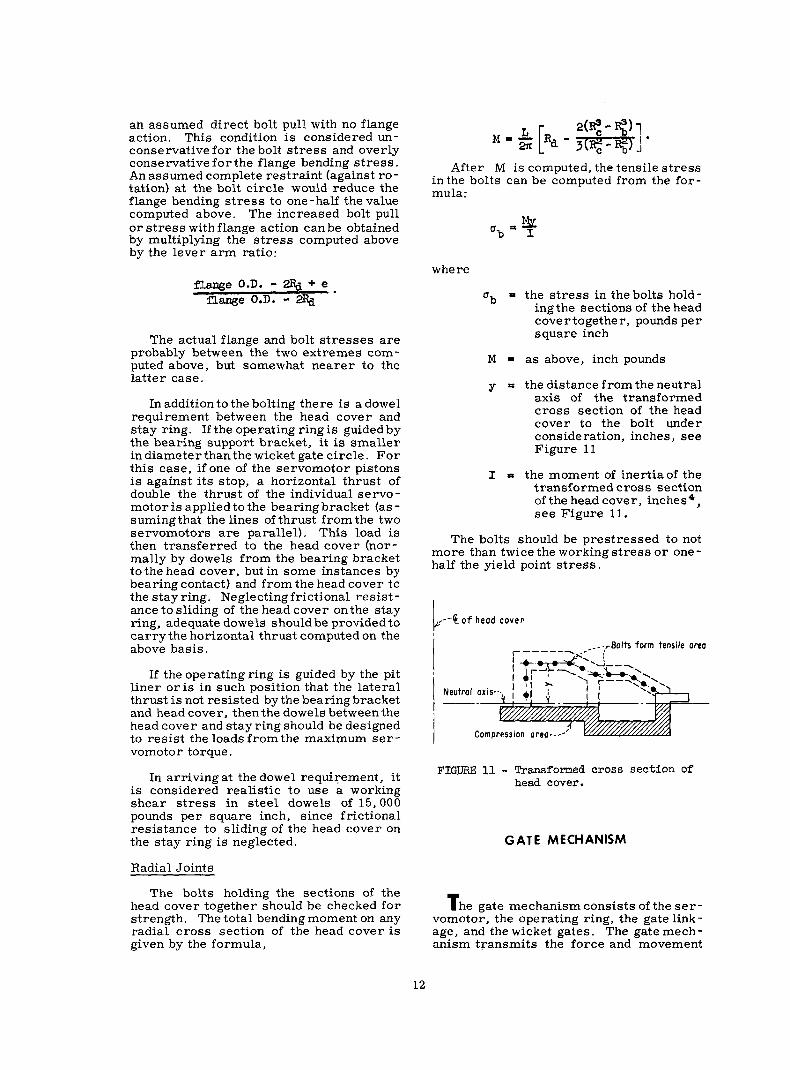
The bolts holding the sections of the head cover together should be checked for strength. The total bending moment on any radial cross section of the head cover is given by the formula,
After M is computed, the tensile stress in the bolts can be computed from the for- mula:
& =b* I
where
% = the stress in the bolts hold - ingthe sections of the head covertogether, pounds per square inch
M= as above, inch pounds
Y = the distance from the neutral axis of the transformed cross section of the head cover to the bolt under consideration, inches, see Figure 11
I = the moment of inertiaof the transformed cross section of the head cover, inches4, see Figure 11.
The bolts should be prestressed to not more than twice the working stress or one- half the yield point stress.
1 ---@of head cover
Neutral
FIGURE 11 - Transformed cross section of head cover.
GATE MECHANISM
T he gate mechanism consists of the ser- vomotor, the operating ring, the gate link- age, and the wicket gates. The gate mech- anism transmits the force and movement
12

,.-Servomotor cylinder
L ,,.-Servomotor piston
FIGURE 12 - Servomotor linkage.
of the servomotor piston to the wicket gates in regulating flow of water to the turbine runne I‘.
Servomotors
The function of the servomotor is to supply the force necessary to operate the wicket gates, The maximum oil pressure is applied to the piston, and the maximum stresses are then determined in the piston, the piston rod, the cvlinder wall, the cvl- inder head and head” bolts, and the flange and flange bolts holding the servomotor to the pit liner. (See the section on attach- ment to stay ring. 1
In the connections between the servo- motor piston rod and the link, and between the link and the operating ring, the shear stress in the pin and the tear-out of the link end should be checked.
The anchorage of the servomotor through the pit liner into the foundation concrete should be adequate to hold the full tension force of the servomotor. This is usually accomplished by rods extending into the concrete with anchor plates at their ends. An analysis of the servomotor backup plate will be found in the section on pit liners.
Consider the relative lengths of the ser - vomotor piston rod and the servomotor link, Figure 12. Since the connection of the link to the operating ring must follow a circular path, although only for a short distance, this point will move laterally with respect to the servomotor piston rod centerline. This movement will cause the link force to act at an angle 0 to the piston rod centerline and to induce a lateral force applied at the end of the piston rod.
Typical installations show the link to be approximately the same length as the piston rod. If the linkis relatively long, this lat- eral force will be small, since the angle 8 is small. However, if the linkis short, the force may be large, because a relatively largeangle may be formed for a given lat- eral displacement.
3
When the lateral displacement of the end of the link is small (so that small angle functions apply), the friction forces in the pins are no longer negligible. These may be considered by the use of friction circles. The radius of the friction circle is:
where
p = coefficient of friction in the joint (may vary from 0.05 to 0.15)
R = pin radius, inches.
The resulting line of action of the link is tangential to the friction circles and acts in such a direction as to oppose the motion.
For small angles, this may result in much smaller deflections of the piston rod than when friction is neglected. (Note that the initial lateral displacement is affected by the clearance between the piston and cyl- inder and the piston rod and guide sleeves, )
Since the thrust of the servomotor is given, the lateral load on the piston rod canbe calculated bymultiplyingthe servo- motor thrust by tan Q . 0 should be the largest possible angle that the link makes with the piston rod. To check for safe working stresses, the following formula maybe applied: (See page 7 of Timoshen- ko’s work on the theory of elastic stability. )
MC P g=--+- f A
where
P = servomotor thrust
The stress in the piston rod should not exceed the yield point stress divided by a suitable factor of safety. If the angle 0 is negligible, the stress should not exceed:
For $ < 60 5 - 10,ooo psi
For $>60 $= 18.ooo

where
L = length of piston rod acting as a cantilever beam, inches
r = minimum radius of gyration of the piston rod cross sec- tion, inches
A = cross section area of piston rod, square inches
P = servomotor thrust, pounds
M = maximum moment caused by the servomotor thrust, inch-pounds
E = modulus of elasticity, pounds per square inch
I = moment of inertia of piston rod, inches 4
8 = acute angle that piston rod makes with link, see Fig- ure 12.
Deflection of the end of the piston rod can be checked by the following formula:20
Y= Cd--
E+ L
I=-
-L tane Ez ) P
Gate Operating Ring
The function of the gate operating ring is to distribute the thrust from the servo- motors to the individual wicket gate link- ages.
The operating ring may be considered as a ring acted upon by a couple consisting of servomotor forces applied to the ring at the link connections and resisted by the dis- tributed reactions of the gate linkage con- nections . See Figure 13.
A number of ring solutions applicable to various problems may be found;=others have been solved for special cases (see Figure 15). However, most actual analy- ses may require superimposing two or more simple solutions.
Stresses inthe operating ring are limit- ed by the maximum servomotorthrust, and are :
MC % T2 sa--+-+- I A A
where
P = maximum servomotor thrust, pounds
20 Raymond J. Roark. op. cit., p. 134. "Raymond J. Roark, op. cit., pp. 156-159.
P P
FIGURE 13 - Forces on gate operating ring.
M = moment in ring from applied load, inch-pounds (see ring solutions)
c = distance to extreme fiber, inches, positive toward $
I = moment of inertia of ring cross section, inches 4
I; = tensioninthe ring fromloads P ’ pounds
T, =-fj
V = shear in ring, pounds
II = number of wicket gates N = radialcomponent ofgatelink
thrust, pounds A = cross-sectionalareaofring,
square inches
The functions of moment and tension shown in Figure 14 should be investigated to determine the location of the maximum stress. Wicket Gate Linkage
A typical gate linkage is composed of the link pin, the gate link, the gate lever, the shear lever and the shear pin. Occasion- ally, a breaking link may be used in lieu of the shear pin.
When the shear pin breaking load is ap- plied to the gate linkage, the allowable stress in the affected parts is two-thirds of the yield stress of the material, A breaking load of the shear pin of approxi- mately 2-l /2 times the normal operating load is considered adequate to prevent
14

FIGURE 14 - Functions of Moment, Shear, and Tension for ring solution shown in Figure 13.
F, + Fx : 2nRp
Y=M, o<x<e
M=M,t F,R(cose-COSX) e<x <2n-+
M-M,+ F,R(cosb'-cosx)+ F,R~cos~-co~x) 2n-l$<x<27r
M,J$ 2(rtx-8+sin8 coS8) cos x-2(7+x-8) COSB
[ -(3-2 Sin28) sin x-2 sin8 1 -g 2(r-x-#+sin@ cOs.0) COSX-2(n-X-0) COS0 [ +(a-2sinx0) sinx-2sin0 1
FIGURE 15 a- Moments in an operating ring.
3 15

progressive failure of the shear pins. Stresses in the gate linkage from the maxi- mum normal operating loads are not to exceed the allowable working stresses.
To determine the maximum normal op- erating forces imposed on the linkage, the force applied to the operating ring by the servomotors (at the point of servomotor attachment) is divided equally among the number of wicket gate linkages, taking note of the radial location of the link pins. The only time that there are forces of any im- portance acting on the wicket gates and link- age is when the gates are in a closed posi- tion, since in the closed position, the nose of the gate acting against the trailing edge of the adjacent gate causes the linkage to become locked. (See Figure 16. ) Then the force on the link is equal to the force applied inthe tangential direction to the link pin by the operating ring divided by the cosine
_---- ---Operating position
----Operating ring
‘-Nose of adjacent gate
FIGURE 16 - Gate linkage mechanism.
of the angle 61 between the link and the tan- gent to the ring.
It may be noted that as O1 approaches 90”, the force on the link in the closed posi., tionbecomes very large. This is known as “toggle action” and is to be avoided.
With the shear pin stressed to the point of failure, the following items should be checked in the gate linkage mechanism, see Figure 17:
a. Bending stress in the gate lever
b. Bending stress in the shear lever
c. Shear stress in the gate key
d. Bearing stress in the gate key
e. Shear tear -out of the linkage pins
f. Shear on linkage pins, each face
g. Tension stress in gate link
h. Column strength of gate link
Wicket Gates
The wicket gates control the flow ofwa- ter to the turbine.
The maximum combined stress in the wicket gates is limited to two-thirds of the yield point of the material at the breaking strength of the shear pins and cannot ex- ceed the allowable working stress under maximum normal operating conditions.
The maximum normal operating condi- tion is considered to be an equal distribu- tion of the maximum servomotor load to all the gates.
The wicket gate must resist the loads from water pressure (including water ham -. mer) and edge loading caused by operation of the gate linkage (see Figure 18).
Items to be checked in the wicket gate are:
a.
b.
C.
Shear stress in the stem
Bending stress in trailing edge
Bending in gate from water pres - sure load
d. Keyway stresses
The nose section of hollow wicket gates may require stiffening diaphragms to pre - vent high local bending stresses at the junc - ture of the gate shell and the shaft.
,rGote lever
L0W
FIGURE 17 - Typical wicket gate linkage system.
5 pin
16

BLOCKED GATE NORMAL CLOSED GATE
L _---- -----_- 1 --------- 4 UNIFORM PRESSURE LOAD
FIGURE 18 - Wicket gate loads.
SPIRAL CASE
SUPPORTING STRUCTURE
T he spiral case supporting structure consists of the jacks, piers, beams, tie rods, columns, rings, and other equipment necessary to hold the spiral case in position during the concreting process,
Jack Loads
The load carried by the jacks consists of the weight of the spiral case, the water contained within the case, and the vertical components of the tie-rod forces, assuming a tie rod prestress of 10,000 pounds per’ square inch. The total rated capacity of all the jacks should be l-112 to 2 times the total vertical load.
The portion of the load carried by any one jack can be evaluated by using a plan (to scale) of the spiral case supporting scheme and estimating the region of load carried by each jack.
Tiedown Bars
The tiedown bars are usually assumed prestressed to 10,000 pounds per square inch, through the turnbuckles. All of the connections should withstand this load.
Considering the entire spiral case, either as a whole or as individual parts, the sum of the vertical components of the tie- rod forces should prevent flotation of the water-filled spiral case when it is im- mersed in grout of specific weight of 100 pounds per cubic foot. Prestressing the tie rods is done to prevent any movement of the spiral case under these conditions.
Jack Pads and Tiedown Lugs
‘The local circumferential bending stress at the jackpads may be determined from one of the following expressions, whichever is applicable:
and when E > 0.05,use A\ o=+l b 0.3R 23
( 1 where
P = the radial component of the computed jackload, pounds
t - the casing shell thickness, inches
R = the radius of the casing at location of jack, inches
b = the radius of the loaded area, inches
In indicates that natural loga- rithms are to be used.
Usually, the loaded area under the jack pad is nearly rectangular rather than cir- cular. To convert to a circular area, an approximation can be made by using an area equal to the rectangular area and thus obtain a value for b to be used in the above ex- pressions, In this connection, it should be noted that the pads made of angles are not always boxed in with vertical webs on the end. It is suggested in most instances that these vertical webs be added to dis- tribute the load more effectively over zs Raymond J. Roar-k, op. cit., Case No. 6, page 270.
p5 Raymond J. Roark, OP. cit., page 263.
17

the area, sothat the condition assumed for analysis will be more nearly realized in practice.
The total circumferential stress at the jack pad would then be the bending stress, as calculated above, plus the shell tension stress due to internal pressure. The shell thickness is normally selected to keep the stress due to internal pressure within the allowable design stress given in the speci- fications. Then it is obvious that adding of the two stresses will give a local stress in excess of that permitted in the specifica- tions as a design stress.
Since this condition exists only locally and since embedment of the spiral case will lessen the loads on the jacks, it is recom- mended that two-thirds of the yield strength of the material be considered as acceptable for the local stresses at the jack pads.
The tiedown lugs should be checked for their adequacy todevelop the forces in the tie bars, allowing comparable values for unit stresses. As an example, the bending stress in the lug (plus tension, if any), should not materially exceed the tension stress in the tie bar which is the source of load.
Support Columns
Columns used in supporting the spiral case should be designed to sustain the rated load of the jack. Many satisfactory column formulas can be foundin structural codes, of which the following are typical:
$ less than 120, $ = 17,000 - 0.48g g 2
0
$ greater than 120, P = 18.000 v
l+i8pc?
where
P * total load on the column, pounds
A = cross-sectional area of col- umn, square inches
L = unsupported length of col- umn, inches
r P least radius of gyration of column cross section, inches.
TURBINE RUNNER AND SHAFT
T he turbinerunner converts the velocity and pressure energy of the water into shaft work.
Turbine Runner or Pump Impeller
Items to be determined for a runner or an impeller are as follows:
a. Ability of the runner to support’ the superimposed loads during erection, if required. Stresses will usually be low in this case, since dimensional sta- bility requirements of the buckets will provide adequate material where it is needed to carry the load. It should be noted that in the case of the Francis- type runner, shims are usually placed between the band and the draft tube liner for leveling purposes. This will con- centrate the load at a few points, caus - ing high bearing stresses.
b. Adequacy of the coupling of run- ners to the shaft and conformance of the coupling connection with the code of ASA Standard B49.1, 1947.24
c. If a propeller-type runner is used, the bending stress in the blades may be found by considering the blade as a can- tilever beam, loaded by forebay pres- sure acting on the total blade area, caus - ing the blade to bend about its weak axis at the runner hub.
d. It may be possible under certain conditions for forces on the runner to lift the rotating parts of the unit off the thrust bearing.
In a Francis-type unit, uplift may be caused when the horizontal projection of the area between the periphery of the run- ner and the lower wearing ring exceeds the horizontal projection of the area between the periphery of the runner and the upper Jvearing ring. This will cause a force to be applied to the unit in the vertical direc- tion owing to the forebay pressure acting on the net annular area. If this force is greater than the weight of the rotating parts plus the hydraulic thrust, the unit may lift off the thrust bearing. Note that in the op- posite case, the resulting force will add to
=I ASME, Shaj? Couplings-Integrally Forfled Flange Type forHydroelectric Units, ASA Standard B 49.1 1947 .
18

that ascribable to the weight of the unit plus the hydraulic thrust. See Figure 19.
In this type of unit, the radial location of the sea l rings may sometimes be changed to eliminate the vertical force. This course is not always possible, and other action must be taken.
In a propeller unit, under conditions of runaway speed, when the wicket gates a r e closed the water in the draft tube will be depressed by the rapidly moving runner blades. (Sometimes this is artificially done with compressed air , in which case uplift will not be present. ) The pressure a t the centerline of the runner which is due to the maximum tailwater elevation acting on the cross-sectional a rea of the draft tube will result in a force acting vertically, Figure 20, If this force exceeds the weight of the rotating parts, uplift of the unit may result.
Uplift of a unit may be remedied by irL- creasing the weight of the rotating parts, by providing a thrust collar to limit the ver - tical movement of the impeller o r runner, o r by eliminating the vertical force causing uplift .
U p p e r Weoring R ing --.,
FIGURE 19 - Uplift forces on a Francis turbine.
,--S h o f t ik
I I
f t t t t t t t t t t? t t t t t I \ ,,-Uplift fo rce on
: r o t a t i n g p o r t s \ -;
FIGURE 20 - Uplift forces on a propeller turbine.
If the thrust bearing contact is broken, s e - vere damage to the thrust bearing is immi- nent.
Turbine -Shaft
Items to be checked on the turbine shaft a r e a s follows:
a. Check the shaft couplings with the code of ASA B49.1. 25
b. The design of the shaft should con- form to the code of ASA B17c.=
c. F o r a Kaplan-type runner, where - in the shaft encloses a blade -operating servomotor, the following items should be determined:
(1) Total combined s t r e s s a t the wall of the shaft servomotor from:
(a) Runner torque;
An increase in the weight of the rotating (b) Unbalanced hydraulic thrust;
parts has a generally favorable effect on the operating characteristics of the unit, (c) Weight of rotating parts; and and is therefore perhaps the most sa t i s - factory solution. Providing a thrust collar (d) Servomotor pressure. to limit the verticalmovement presents the difficulty of providing clearance for lifting (2) Stress in the coupling bolts due
the unit when starting it, and at the same 25
time limiting the vertical movement while ASME, Sl~aft Coupllnqs-Integrally Forged Flange Type for Hydroelectric Units, ASA Standard B 49.1 1947.
running the unit. The only advantage of such a thrust collar i s the prevention of ASME, Code for peslgn of Transmtsslon Shafting, ASA contact of the runner with the head cover. Standard B I I C , 1927 (1947).

TkBLE6 - Computation for critical. speed
i Wi Ai A2i Wi Ai Wi A2i
I
to the above effects, including flange action,
(3) Bending stress in flanges of the servomotor may be found by using the procedure as for the spiral case.
d. A critical speed study should be made of the hydroelectric unit of which the turbine shaft is a component. The first critical speed is the speed of rota- tion of the unit which coincides with the lowest natural frequency of the rotating system in lateral vibration. Operation at this speed must be avoided to prevent the excessive vibration associated with resonance. As ageneral rule, the first critical speed should be greater than 4 / 3 of the maximum runaway speed of the unit, or approximately 2 and l/2 times
cycles per second,
where ni is the static deflection ofthe point i on the shaft at the load Wi. This method is approximate, and requires the assumption of a deflection curve of the vibrating shaft. Timoshenko also states that in certain cases the rigidity of the sup- port is low enough to produce a substantial effect on the magnitude of the critical speed. It is only necessary to add to the computed static deflections the displacements caused by the deformation of the supports normal to the centerline of the shaft.
The normal vertical hydroelectric unit may be represented as shown in Figure 2 1.
the normal operating speed.
Timoshenko gives the following f0rmUl.a for the gravest mode of vibration: 27
*’ s. TimOShenkO ana D. H. Young, Vibration problems in Enqineerinq, 3rd Ed., 1955, page 37.
ss op. cit., page 40.
ShafCdd
FIGURE 21 - Idealized shaft arrangement.
20

---
t
_/- -- -1 / 2 7,,,, l-r- -A--- 55; r I I 3 4
FIGURE 22 - Deflections of shaft from inertia loads.
,-Unit Load ‘. I ,-- A--, I
-$--- A7 h
b21 J-----a
6, 6 31
Unit Load,
I A ,-- /
I -- I -- h--a 8 32
(-Unit Load I ‘-4 ry-
FIGURE 23 - Unit load deflections of shaft.
21

Figure 22 shows the assumed shape of the deflection curve, and directions of applied loads for the lowest critical speed,
The distributed weight of the shaft may be concentrated as follows:
a. For a cantilever beam, the dis- tributed weight of w.8 may be concen- trated at the end of a cantilever in the amount
+ 1 owe b. For a fixed-ended beam, the dis-
tributed weight of w.8 may be concen- trated at the midpoint in the amount
if Wk?
c. For a beam on simple supports, the distributed load w.E may be con- centrated at the midpoint in the amount $ wt?
Thus the distributed weight of the unit may be broken down into a finitenumber of concentrated weights.
In evaluating the frequency, the tabular form of Table 6 is suggested. Utilization of Maxwell’s laws of reciprocal deflections gives:
and
To find 4X> 6219 Se& 9 and 6, (the deflections of Points 1, 2, 3, and 4 due to a unit load at Point 11, the unit is treated as shown in Figure 23. A similar proce- dure is followed to find tZj Ba2, b42~ Es, 9 6 43’ 644 Timoshenko gives a typical pro- cedure for this type of calculation.*a
The reader is referred to any text on statically indeterminate structures for the procedure to be used in computing deflec- tions of the shaft. It should be noted that removal of one generator guide bearing support will make tine problem statically determinate.
aaS. Timoshexiko ana d. H. Young, Vibration Problems in Engineering, 3rd Ed., 1955, pp. 369-391.
GUIDE BEARING SUPPORT BRACKET
T he guide bearing support bracket should be designed to resist the maximum loads imposed on it by the turbine shaft and the gate operating ring. Since the bracket takes many forms, only general recommenda- tions will be made regarding its analysis.
The guide bearing support bracket should be of relatively heavy construction to provide rigid support to the turbine guide bearing in both lateral and circumferential directions, as shown in Figure 24. Fail- ure to provide such rigidity may cause a variety of difficulties.
FIGURE 24 - ‘typical guide bearing bracket.
The load from the shaft maybe assumed by considering the rotating parts of the unit as a horizontal beam on simple supports to find the reaction at the turbine guide bear- ing, Figure 21. To this force is added the unbalanced lateral hydraulic thrust on the runner. Load from the servomotors may be takenas twice the thrust of one servomotor, if the operating ring is carried by the sup- port bracket.
The manner in which the bracket carries the imposed loads depends upon its basic design. Various modes of structural action may be assumed, but the loadsare usually carried by shear stress only. Since the vertical ribs which are parallel to the di- rection of load application offer much more resistance to distortion than those normal to the load, only the components of load parallel to the ribs should be considered.
22

BEARING SUPPORT BRACKET
SECTION A-A
FIGURE 25 - Guide bearing bracket.
Dowels should be provided between the bracket and the head cover, as described in the section on head covers.
PIT-LINER
T he pit-liner serves as an internal form and as a protective liner for the surround- ing concrete. The servomotor pistons, lu- brication oil systems, access stairways, auxiliary piping, and occasionally the oper - ating ring may be mounted on or in the pit - liner.
The pit-liner may be loaded by the ex- ternal pressure due to maximum tailwater elevation (in some installations the forebay pressure maybe applied), the weight of the superimposed concrete and the unit, and forces due to servomotor operation.
Collapsing Stability
The pit-liner, being well anchored to the surrounding concrete and having circum- ferential stiffeners, is not likely to col- lapse, A check may be made using the Saunders and Windenburg formula:30
where
P - collapsing pressure, pounds per square inch
t - thickness of the pipe shell, inches
L * length between circumferen- tial stiffeners, inches
D = diameter of pit-liner, inches
Occasionally a large area of flat plate may be encountered. In this case, the for- mula, M - - kqa2 on page 25, may be ap- plicable. If not, Roark offers solutions for a wide variety of cases.el
Superimposed Loads
The weight of the unit and a portion of the superstructure above the pit-liner may be carried by the pit-liner and transmitted through the stay ring to the foundation. Stresses in the pit-liner may be found for this load by the simple formula:
P S=- A
where
P - superimposed load, pounds
A * 2nr-t
r = radius to middle surface of piMiner shell, inches
t = thickness of shell, inches
The pit-liner should also be checked for collapsing stability as a thin cylindrical shell subjected to er:d load. Timoshenko gives the formula: aa
soHarold E. Saunders and Dwight F. Windenburg, Strength of Thin Cylindrical Shells Under External Press~~c, 1931, page 209.
” Raymond J. Roark, 00. cit., page 192. =*S. Timoshenko and J. M. %ere, Theory of Elastic
Stability, 2nd Edition, 1961, page 458.
23

where
S = cr compressive stress at buck- ling, pounds per square inch
E = modulus of elasticity of pit- liner material, pounds per square inch
V = Poisson16 ratio
Servomotor Supports
The servomotor recesses of the pit-liner are not ordinarily designed to carry the servomotor load but merely to support the dead weight of the servomotor and transmit the servomotor reaction to the adjacent concrete. This is usually done by putting a large plate of substantial thickness in back of the servomotor to distribute the thrust. To resist the opposite or tensile effect, long rods with plates on the end are usually em- bedded in the concrete.
The backupplates transmitting the ser- vomotor thrust into the foundation concrete require investigation. These plates may be treated as shown in Timoshenko’s ex- ample.” Figure 26 is a typical example. The maximum stress is
where
u P stress, pounds per square inch
T = servomotor thrust, pounds
t P plate thickness, inches
9 = intensity of uniform founda - tion reaction, pounds per square inch
a I outer radius of plate, inches
b = inner radius of plate, inches
If the pit-liner is designed to carry the load of the servomotor, it may be analyzed as a ring upon which are impressed two equal and opposite forces consti.tuting a
93% Timoshenko and S. Woinowsky-Krieger. Theory of Plates and Shclls,Znd. Ed., 1961, page 62.
'-Servomotor thrust
6
5
4
K 3
I 2 3 4 5
o/ b FIGURE 26 - Servomotor thrust plate
loading.
couple, the moment of which is resisted by shear forces uniformly distributed a- round the periphery of the ring. Further cognizance should be taken of the vertical distribution of these forces.
DRAFT TUBE LINER
T he draft tube recovers the residual ve - lo&y energy of the water leaving the tur- bine runner . Structurally, the draft tube liner is a relatively unimportant part of a hydraulic turbine installation since it has no primary structural loads to carry. How- ever, it must be capable of withstanding loads caused during erection and loads caused by external hydrostatic pressure during normal operation. Usually, the specifications state that the ribbing and anchorage shall be designed for full exter- nal hydrostatic pressure with the tailwater at a specified elevation and with an abso- lute pressure of one-half atmosphere inside the draft tube liner.
24

Collapsing Stability
With circumferential ribbing and radial tie rodsattached to the ribbing, the circu- lar portion of the draft tube is not likely to collapse. A circular section between ribs may be checked for collapse using the Saunders and Windenburg formula: 34
=/a
Pt73.4Xlo=~+ & 0
where
P P collapsing pressure, pounds per square inch
t = thickness of the pipe shell, inches
L = length between circumferen- tial ribs, inches
D P diameter of the pipe shell, inches
s4 ~a~&3 E. Saunders and Dwight F. Windenburg. op. cit., page 209.
msum 27 - Draft tube liner.
Ordinarily this computed collapsing pressure will be much greater than the de- sign pressure, indicating that collapse of this portion of the draft tube has not been a major factor in its design.
At its downstream end, the draft tube flares out horizontally, creating relatively large, flat sections which must be able to withstandexternaldesignpressure. These flat sections of the draft tube should be checked for structural adequacy.
Referring to Figure 27, the plate can be analyzed as a uniformly-loaded, flat, rec- tangular plate with built-in edges. The maximum stress will occur at the middle of the longer side of the rectangle. The maximum stress is given by:
where
u = maximum bending stress, pounds per square inch
M = bending moment at the mid- dle of the long side of the plate, inch-pounds per inch
t = thickness of the plate, inches
The moment M is a function of the lat - era1 dimensions of the plate and the magni- tude of the uniform load. M is given by:
M = - kqa2
where
k = a constant depending on the dimensions of the plate
9 = uniform load, pounds per square inch
a = shorter dimension of the plate, inches
The values of k listed below are taken from Timoshenko: 33
where
b = the longer lateral dimension of the plate, inches . For values of b/a greater than 2.0, the value of k is virtually con- stant at 0. 0833.
s5S. Timoshenko and S. Woinowsky-Krieger, Theow of Phtcs and ShcIls.lnd Ed., 1961. page 202.
25

b/a k
1.0 0.0513
1.1 0.0581
1.2 0.0639
1.3 0.0687
1.4 0.0726
1.5 o.o7!57
1.6 0.0780
1.7 0.0799
1.8 0.0812
1.9 0.0822
2.0 0.0829
Referring again to Figure 27, the sec- tion of the draft tube liner between the tie rods at a and b may be analyzed as a fixed-end beam of length L . The beam will consist of the circumferential rib act- ing as the web of a T-section and a portion of the plate acting as a flange. The width of plate to be included in the effective flange should be 0.181 L where L span of the fixed-end beam.se
is the The uniform
load to be applied to the beam is:
w = qa AE = A cos up
where where w = load per unit length of beam,
pounds per inch
4 = hydrostatic pressure, pounds per square inch
a c length between circumferen- tial stiffeners, inches
Anchorape
The anchorage rods attached to the flat portions of the draft tube liner should be numerous enough andlarge enough to sup- port the design hydrostatic load on the liner. To compute the stress in an individual rod, compute the total hydrostatic load on the portion of the liner which the rod will have to support, then divide by the cross-sec- tional area of the rod.
se G. Murray Boyd, Effective Flange Width of Stiffened Plating in Lotqiludinal Bending. 1946.
The anchor rods on the draft tube liner, which are oriented so that they exert a downward force on the liner, mustbe cap- able of holding the liner in place against the maximum uplift force developed during embedment of the liner in concrete. The numerical value of the uplift force is never known exactly; in fact, the general question is controversial. In the absence of specific data about uplift pressures, a method will be suggested for determining the order of magnitude of the stresses developed in the holddown rods.
Assume the draft tube liner to be im- mersed in fluid grout of specific weight 100 pounds per cubic foot. Assume the liner to be submerged from its outlet end to the set - tion where it becomes circular. For this portion of the draft tube liner, compute the volume and the weight of the liner. The uplift force is then
F=lOOV-W
where
V = the computed volume, cubic feet
w = the computed weight, pounds
The area of a holddown rod effective in resisting the uplift force is
AE = the effective areaof the rod, square inches
A = the gross area of the rod cross section, square inch- es
cp = the angle which the rod makes with the vertical
The average tensile stress in the holddown rods is then
F u=c-
where C AE is the summation of effective cross-sectional areas of all rods exerting a downward force on the section of draft
26

MISCELLANEOUS ITEMS
Test Bulkheads
PROFILE
: Critical I
bending : section d\I
SECTION S-E
FIGURE 28 - Cast pier nose.
tube liner. This loading on the holddown rods is severe, and judgment must be exer- cised in interpreting the importance of the computed u .
Pier Nose
Frequently, the larger draft tubes are designed with multiple outlets which re- quire pier noses where the draft tube splits. These pier noses are usually required to carry large loads which must be trans- ferred from the generator floor to the foun- dation. Ordinarily, the pier noses are of cast steel and each nose is of special design, requiring a special analysis. The cast pier nose may develop high stresses at the top and bottom where the nose fairs intothe concrete of the powerhouse structure. These regions should be checked forbend- ing stresses, If the pier nose is filledwith concrete, the concrete will carry a portion of the load as a short column, Only that portionof the concrete which forms a con- tinuous column throughout the length of the pier nose should be used as effective for carrying load. See Figure 28. Figure 29 shows an alternative welded design.
Manhole and Man Door
Owing to the low pressure on the draft tube, the manhole and man door usually are not critical. However, they may be ana- lyzed by the procedure set forth for spiral case manholes and man doors.
Test ring, . --Normally the test ring used to close the stay ring opening is subjected to high external pressures, and must be checked for its collapsing strength. The stability of the test ring may be provided by stiffener rings or by support points on the ring circumference. In the latter case, a spider maybe used, or support bars in- serted in the gate stem holes may act as support points for the test ring.
The collapsing pressure of a steel test ring may be determined from the follow- ing expression when stiffener rings are used:37 33
5/2 (>
k P=73.4x10⁶ D
( > A! D
where P f collapsingpressure, pounds
per square inch
t = test ring shell thickness, inches
a7 John Parmakian, Air-inlet Values for Steel Pipelines, 1950.
‘*Harold E. Saunders and Dwight F. Windenburg, op. ClL, 1931.
SECTION A-A
PROFILE SECTION B-B
FIGURE 29 - Welded pier nose.
27

D = outer diameter of test ring, inches
L = spacing between stiffener rings, inches
The stiffened structure may collapse as a whole in which case the collapsing pres- sure is given by:
where
E = modulus of elasticity, pounds per square inch
n = minimum number of waves
D = outer diameter of test ring shell, inches
L = spacing between stiffener rings, inches
I = moment of inertia of the cross section of the com- plete stiffened ring sec- tion, 3s inches 4
L’ = total height of test ring sub- jected to external pres- sure, inches
r = radius to c. g. of the com- plete stiffened ring sec- tion, inches
When the test ring is dependent for its stability upon support points on its circum- ference, the following equation may be used to determine the collapsing pressure; *o
p o 2 Et3(n2-1) 3ti
where p P collapsingpressure, pounds
per square inch
t = test ring shell thickness, inches
D = diameter of the outer sur- face of the test ring shell, inches
E = modulus of elasticity of the test ring material, pounds per square inch
FIGURE 30 - Test ring.
n = minimum number of waves into which the shell can buckle
The number of waves is determined by the number of equally spaced points at which the ring is supported. The minimum num- ber of waves is 2. If there are an even number of support points, n is equal to one-half the number of support points. If there are an oddnumber of support points, n is equal to the number of support points. Figure 30 indicates a test ring having 12 points .of support for which II = 6.
External constraint by the stay ring is not considered to assist the test ring in resisting buckling.
Test heads. --The pressure bulkhead at the inlet to the spiral case may be hemispheri- cal, but this is often not the case. In any event, there have been established certain design criteria for pressure bulkheads which should be observed.dr
Although high local bending stresses may exist near the juncture of the bulkhead andinlet section of the casing, this condi- tion would normally be permissible if the above design criteria are observed. Nev- ertheless, these bending stresses shouldbe determined, which for hemispherical and ellipsoidal heads can be treated as follows:
Timoshenko gives a discussion of dis- continuity stresses when a hemispherical
a9 ‘Z’he effective width of shell acting with the stiff- ener ring may be taken as the ring thickness plus 1.56 &z , where r is the radius of the shell in inches, provided the effective widths from adja- cent stiffener rings do not overlap, in which case the effective width would extend tc midspan be- tween stiffeners. See Reference (9), pages 43-49, for discussion on equivalent flanges.
‘O S. Timoshenko, Theory of Elastic Stability, 1961, page 478.
4l Rules for Construction of Unfired Pressure Vessels, op. cil.
28

head is used.” The approximate solution of the problem assumes that the bending is of importance only in the zone of the spherical shell close to the joint, and that this zone can be treated as a portion of a long cylin- drical shell of the radius of the attached cylinder.
If the thickness ofthe spherical and the cylindrical portion of the vessel is the same, the moment at the juncture vanishes, leaving only a shear. This shear will in- duce bending in the shellwhich when com- bined with the membrane stress gives (using a hemispherical head),
uxbd = 1.293 $$ for the maximum longi-
tudinal stress in the cylindrical shell
%ax) = 1.032 y for the maximum hoop stress in the cylin- drical shell
where
r = radius of cylinder, inches
P = internal pressure, pounds per square inch
t = cylinder Wall thickness, inches.
The membrane stress in the hemispher- ical head is smaller than that in the cylin- der, and since the discontinuity stress iS the same, the maximum combined stress in the head is always less than that com- puted above for the cylinder.
When the dished head has the form of an ellipsoid of revolution the discontinuity
stresses increase in the proportion of P ,i? ’
where r and b are the semimajor and semiminor axes of the ellipse, respec- tively. The combined stress in the cylin- drical shell becomes (with the notation as previously defined):
uxhax) = 1+0.293$ ( >
EE
utb2d P 1+0.032$
( >
2-t 7
The above is considered as represen- tative forthe stress in the cylindrical shell when the bulkhead is sphericalls dished (torispherical). Then r and b can be determined as for an ellipsoidal head.
Bottom Ring
The bottom ring may be analyzed as a ring loaded by the uniformly distributed radial forces caused by pressure on the wicket gates. There will be negligible bending present, and the stress is
where St - F
P I load from wicket gates as- sumed uniformly distrib- uted over distance be- tween gates, pounds per inch
r = radius to center of wicket gate stems, inches
A = cross-sectional area of bot- tom ring, square inches.
“S. Timoshenkoand S. Woinowaky-Krieger, Them Of Plates and Shclls,2nd Ed., 1961, pages 461-485.
29


LIST OF REFERENCES
(1) Timoshenko, S., Theory of Plates and Shells, McGraw-Hill Book NewPork, Second Ed., 1959
(13) Boyd, G. Murray, Effective Flange Width of Stiffened Plating in Longitudinal Bendmg, Engmeermg, December 27, 1946
(2) Cornwell, F. E., Miscellaneous Notes (14) Evans, W. E., on the General Problem of Flange Design
Stress Analysis of a
bureau of Reclamation, Denver, ColoTadA Hydraulic Turbine Stay Ring, MathematicaI Report No. 105 U S . . D epartment of the
(3) Roark, Raymond J., Formulas for Interior, Burea; of Reclamation, Denver, November 15, 1954
Stress andstrain, McGraw-Hill Book Com- pany, Inc., New York, Third Ed., 1954
(4) Timoshenko, S., Strength of Materials, Part II, D. Van Nostrand Company, Inc.,
(15) Bovet, G. and Th. , Contribution to the Stress Analysis of a Tubular Scroll, Information Techniques Charmilles, No, 1, 1945, pages 62-73
New York, Third Ed., 1956
(5) Timoshenko, S., Theory of Elasticity McGraw-Hill Book Company, Inc., New York, 1951
(16) Bovet, Th. , Calculation of the Me- chanical Strength of pira S Head Turbines, Information T Charmilles, No. 7, 1958
echmques
Steel Pi elines Transactions -1 Engineers, v. 115, 1950, in the Vicinity c page 438 Pressure Vessels, v. 41, No. 2, B y ’ ulletm
No.
(6) Parmakian, John, Air-Inlet Valves for of American
(17) Hogan, Mervin B., A Survey of Lit- erature Pertaining to Stress Distribution
)f a Hole and the Design of
, Utah Engineering. Experiment Sta- (7) Timoshenko, S., Theory of Elastic Sta- b$li$+l!$G;;;;Hill book Company, Inc.,
tion, Department of Mechanical Engineer- p;hm;;;sity of Utah, Salt Lake City,
(8) Rules for Constructionof UnfiredPres- sure Vessels, Section urn, ASME Boiler and Pressure Vessel Code, AmericanSoci- ety of Mechanical Engineers, New York, 1959
(9) Penstock ttnilysis and Stiffener Design, Part V Bull . 5 Technical Investiga- tions, Boulder Cadyon Project Final Re- ports, U. S. Department of the Interior, Bureau of Reclamation, Denver, 1940
(10) Hetenyi, M., Beams on Elastic Foun- dation, University of Michigan Press, Ann Arbor, 1946
(11) Timoshenko, S. , and Young, D. H. , Vibration Problems in Engineering, D. Van mostrand Company, Inc. , New York, Third Ed., 1955
(18) Phillips, H. Boyd, and Allen, Ira E., Stresses Around Rectangular Openings in a Plate, Proceedings of the American Society mil Engineers, Journal of Engineering MechanicsDivision, v. 86, No. EM3, June 1960
(19) Dolan, T. J. , and McClow, J. H. , The Influence of Bolt Tension and Eccentric Loads on the Behavior of a Bolted Joint, Proceedmgs of the Society for Experimen- tal Stress Analysis, v. VIII, No. 1, 1950, pages 29-43
(20) Shaft Couplings -- Integrally Forged Flange Type for Hydroelectric Units, A- merican Standards Association, B49.1, 1947, published by the American Society of Mechanical Engineers
(12) Saunders, Harold E., and Winden- (21) Code for Design of Transmission burg, Dwight F., Strength of Thin Cylin- Shafting, AmericanStandards Association, drical Shells Under External Pressure, B17c, 1927, reaffirmed in 1947, sponsor- Transactions, American Society of Me- ed by the American Society of Mechanical chanical Engineers, v. 53, 1931 Engineers
31
*U.S. GOVERNMENT PRINTING OFFICE: 1992--838.018