Stress Analysis During Crack-Microcrack Interaction Using ... · Unlike the analytical methods of...
3
Abstract— This work presents the results from an analysis which considers the interaction between a crack and a surrounding microcrack. Method of complex variables is used to derive explicit expressions for the stress intensity factors. Results are computed and discussed for a variety of geometrical configurations of microcracks, with the intent of developing an understanding of the shielding and amplification phenomena. A qualitative experimental technique which is Photoelasticity is used to justify the patterns of the iso-stress. Index Terms—amplification, method of complex variables, microcrack, stress intensity factor. I. INTRODUCTION Progress in the understanding of fracture has long been inhibited by incomplete mathematical descriptions of conditions prevailing near a crack tip. The subject has received an increasing amount of attention from researchers in recent years [1,2, 4, 5] The complex variable method gives elegant mathematical relations involving the unknown stresses and displacements. The three basic equations of plane elasticity in complex variables are given according to Muskelishvili [1] as; (1) Where are potential functions Manuscript received on February 2010. Hadda HADJAB is IAENG member and Associate Professor with the University of Sciences & Technology Houari Boumedienne Civil Engineering Faculty (corresponding author phone: 00 213 24 72 24; fax: 00 213 24 79 14; e-mails: hhadjab@ usthb.dz / [email protected]). A. hypothesis Our goal is to determine and by taking into account the interaction between a macrocrack and a surrounding microcrack. The interaction is obtained by the superposition of two single poles: (2) here, (3) Corresponding to a singular point located at z 0 from the main crack. We consider first, an isolated straight dislocation line in the x direction and let (b) the Burgers vector around the dislocation line. A powerful method of analysis as for this case is based on the representation of a crack by a combination of dislocation (dipoles) as: (4) (5) ) For a finite body, the solution is found by writing the complex stress functions and as: (6) (7) Stress Analysis During Crack-Microcrack Interaction Using Complex Variables Method and Photoelasticity Hadda HADJAB 4 Re[ ( )] 2 2[ '( ) ( )] 2 ( ) ( () ( )) () xx yy yy xy xx x y z i z z z Gu iu k z z dz z z 0 1 0 1 1/2 0 0 1/2 2 0 0 0 0 ( ) ( ) ( ) z z z z z z z 1 2 1 2 d d d d d d 0 0 0 0 0 0 0 0 (, , ) (, , ) i i d i i d zz z e dr e dr z z zz z e dr e dr z z 0 0 0 0 0 (, ) [ (, ) (, ) ( ) (, ) ( )] zz Fzz Fzz z z Rzz z 0 1 1 1 (, ) () () '() zz z z z z Proceedings of the World Congress on Engineering 2010 Vol II WCE 2010, June 30 - July 2, 2010, London, U.K. ISBN: 978-988-18210-7-2 ISSN: 2078-0958 (Print); ISSN: 2078-0966 (Online) WCE 2010
Transcript of Stress Analysis During Crack-Microcrack Interaction Using ... · Unlike the analytical methods of...
Abstract— This work presents the results from an analysis which considers the interaction between a crack and a surrounding microcrack. Method of complex variables is used to derive explicit expressions for the stress intensity factors. Results are computed and discussed for a variety of geometrical configurations of microcracks, with the intent of developing an understanding of the shielding and amplification phenomena. A qualitative experimental technique which is Photoelasticity is used to justify the patterns of the iso-stress.
Index Terms—amplification, method of complex variables, microcrack, stress intensity factor.
I. INTRODUCTION
Progress in the understanding of fracture has long been inhibited by incomplete mathematical descriptions of conditions prevailing near a crack tip. The subject has received an increasing amount of attention from researchers in recent years [1,2, 4, 5]
The complex variable method gives elegant mathematical relations involving the unknown stresses and displacements. The three basic equations of plane elasticity in complex variables are given according to Muskelishvili [1] as; (1) Where are potential functions
Manuscript received on February 2010. Hadda HADJAB is IAENG member and Associate Professor with the
University of Sciences & Technology Houari Boumedienne Civil Engineering Faculty (corresponding author phone: 00 213 24 72 24; fax: 00 213 24 79 14; e-mails: hhadjab@ usthb.dz / [email protected]).
A. hypothesis
Our goal is to determine and by taking into account the interaction between a macrocrack and a surrounding microcrack. The interaction is obtained by the superposition of two single poles:
(2) here,
(3) Corresponding to a singular point located at z0 from the main crack. We consider first, an isolated straight dislocation line in the x direction and let (b) the Burgers vector around the dislocation line. A powerful method of analysis as for this case is based on the representation of a crack by a combination of dislocation (dipoles) as: (4) (5) ) For a finite body, the solution is found by writing the complex stress functions and as:
(6)
(7)
Stress Analysis During Crack-Microcrack Interaction Using Complex Variables Method
and Photoelasticity
Hadda HADJAB
4Re[ ( )]
2 2[ '( ) ( )]
2 ( ) ( ( ) ( )) ( )
xx yy
yy xy xx
x y
z
i z z z
G u iu k z z dz z z
0 1
0 1
1/ 20 0
1/ 2 20 0 0 0
( )
( ) ( )
z z
z z z z z
1 2
1 2
d d d
d d d
0 00 0
0 00 0
( , , )
( , , )
i id
i id
z z z e dr e drz z
z z z e dr e drz z
0 0 0 0 0( , ) [ ( , ) ( , ) ( ) ( , ) ( )]z z F z z F z z z z R z z z
0 1 1 1( , ) ( ) ( ) ' ( )z z z z z z
Proceedings of the World Congress on Engineering 2010 Vol II WCE 2010, June 30 - July 2, 2010, London, U.K.
ISBN: 978-988-18210-7-2 ISSN: 2078-0958 (Print); ISSN: 2078-0966 (Online)
WCE 2010

(8)
(9) Where Equations (1), allow us to determine the stress field and the stress intensity factor (SIF) which are represented by equation (10) and (11) respectively
(10)
(11)
Interpretation of the results Fig. 1 represents the stress field represented by equation 10. As we approach to the macrocrack tip, stress field is higher, justifying the v notch effect, then it’s decreased. Orientation and position of microcrack to the macrocrack, influence the amplification and shielding effects (see Fig. 2). Shielding effect is predominant, when the orientation of the microcrack is considered in the interval between 0° to 110° beyond that it is the amplification effect which takes place. One can conclude: + the stress field is influenced by the microcrack presence + The supremacy of the shielding is = 110°. + Amplification, shielding and other phenomena define the Fracture Process Zone (FPZ)
Figure 1: iso stress
II. EXPERIMENTAL TECHNIQUE (PHOTOELASTICITY)
Photoelasticity is an experimental method to determine stress distribution in a material.
Unlike the analytical methods of stress determination, photoelasticity gives a fairly accurate picture of stress distribution even around abrupt discontinuities in a material. The method serves as an important tool for determining the critical stress points in a material and is often used for determining stress concentration factors in irregular geometries.
III.1 PRINCIPLES
The method is based on the property of birefringence, which is exhibited by certain transparent materials. Birefringence is a property by virtue of which a ray of light passing through a birefringent material experiences two refractive indices. The property of birefringence or double refraction is exhibited by many optical crystals. But photoelastic materials exhibit the property of birefringence only on the application of stress and the magnitude of the refractive indices at each point in the material is directly related to the state of stress at that point. Thus, the first task is to develop a model made out of such
0 00
00
0
1 ( )( , ) [1 ] /( )
2 ( )
( , )( , )
zF z z z z
z
F z zR z z
z
( )
( 1)
ix yG b ib e
i k
3/ 2
3/ 2
3/ 2 3 / 2
3 5[( cos( 3 / 2) sin( )]
2 23 5
[( cos( 3 / 2) sin( )]2 2
3 3[( sin .cos( ) sin . ]
2 2
xx
yy
ixy
r dr
r dr
r e dr
3/ 2 3 52 [( cos( 3 / 2) sin( )]
2 2IK r dr
3/ 2 3 / 2 3 52 [( sin sin cos( )]
2 2i
IIK r e dr
Proceedings of the World Congress on Engineering 2010 Vol II WCE 2010, June 30 - July 2, 2010, London, U.K.
ISBN: 978-988-18210-7-2 ISSN: 2078-0958 (Print); ISSN: 2078-0966 (Online)
WCE 2010
materials. The model has a similar geometry to that of the structure on which stress analysis is to be performed. This ensures that the state of the stress in the model is similar to the state of the stress in the structure.
When a ray of plane polarised light is passed through a photoelastic material, it gets resolved along the two principal stress directions and each of these components experiences different refractive indices. The difference in the refractive indices leads to a relative phase retardation between the two component waves. The magnitude of the relative retardation is given by the stress optic law:
x - y = c.N / e (12)
Where c is the phoelastic sensivity, e is the specimen thickness, N is fringe order (integer) and σ x is the first principal stress, and σ y is the second principal stress.
The two waves are then brought together in a polariscope. The phenomena of optical interference takes place and we get a fringe pattern, which depends on relative retardation. Thus studying the fringe pattern one can determine the state of stress at various points in the material.
III.2 Isoclinics and isochromatics Interpretation
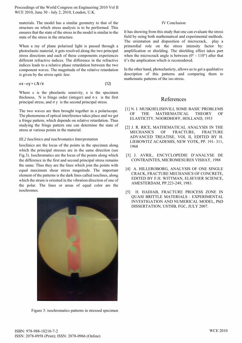
Isoclinics are the locus of the points in the specimen along which the principal stresses are in the same direction (see Fig.3). Isochromatics are the locus of the points along which the difference in the first and second principal stress remains the same. Thus they are the lines which join the points with equal maximum shear stress magnitude. The important element of the patterns is the dark lines called isoclines, along which the strain is oriented in the vibration direction of one of the polar. The lines or areas of equal color are the isochromes.
Figure 3: isochromatics patterns in stressed specimen
IV Conclusion
It has showing from this study that one can evaluate the stress field by using both mathematical and experimental methods. The orientation and disposition of microcrack, play a primordial role on the stress intensity factor by: amplification or shielding. The shielding effect takes part when the microcrack angle is between (0° - 110°) after that it’s the amplication which is reconsidered.
In the other hand, photoelasticty, allows us to get a qualitative description of this patterns and comparing them to mathematic patterns of the iso-stress.
References
[1] N. I. MUSKHELISHVILI, SOME BASIC PROBLEMS OF THE MATHEMATICAL THEORY OF ELASTICITY, NOORDHOFF, HOLLAND, 1953
[2] J. R. RICE, MATHEMATICAL ANALYSIS IN THE MECHANICS OF FRACTURE, FRACTURE ADVANCED TREATISE, VOL II, EDITED BY H. LIEBOWITZ ACADEMIS, NEW YOTK, PP. 191- 311, 1968
[3] J. AVRIL, ENCYCLOPEDIE D’ANALYSE DE CONTRAINTES, MICROMESURES VISHAY, 1988
[4] A. HILLEROBORG, ANALYSIS OF ONE SINGLE CRACK, FRACTURE MECHANICS OF CONCRETE, EDITED BY F.H. WITTMAN, ELSEVIER SCIENCE, AMESTERDAM, PP.223-249, 1983.
[5] H. HADJAB, FRACTURE PROCESS ZONE IN QUASI BRITTLE MATERIALS : EXPERIMENTAL INVESTIGATION AND NUMERICAL MODEL, PhD DISSERTATION, USTHB, FGC, JULY 2007.
Proceedings of the World Congress on Engineering 2010 Vol II WCE 2010, June 30 - July 2, 2010, London, U.K.
ISBN: 978-988-18210-7-2 ISSN: 2078-0958 (Print); ISSN: 2078-0966 (Online)
WCE 2010