STRENGTHENING SLENDER CIRCULAR CONCRETE COLUMNS … · 2019-05-01 · values of the load from zero...
10
ST13-1 Building Tomorrow’s Society Bâtir la Société de Demain Fredericton, Canada June 13 – June 16, 2018/ Juin 13 – Juin 16, 2018 STRENGTHENING SLENDER CIRCULAR CONCRETE COLUMNS WITH A NOVEL HYBRID FRP SYSTEM Khorramian, Koosha 1 and Sadeghian, Pedram 1,2 1 Dalhousie University, Canada 2 [email protected] Abstract: In this paper, the performance of slender circular concrete columns strengthened with a novel hybrid system of longitudinal bonded fiber-reinforced polymer (FRP) prefabricated laminates and transverse FRP wraps is investigated. The idea is to improve the axial load carrying capacity of slender concrete columns by providing high modulus longitudinal carbon FRP (CFRP) laminates through enhancing the flexural stiffness of the column, and laterally support the longitudinal laminates to allow them function and not to buckle before reaching crushing. To provide lateral support for the longitudinal laminates glass FRP (GFRP) wraps were used which in addition enhances the strength of concrete through confinement. The system is investigated using an analytical-numerical model considering the second-order deformation of the slender columns. The model also considers nonlinearity in material and the confinement effects. The model is verified versus experimental test data for slender concrete columns wrapped with FRP. However, there is no test data for the hybrid longitudinal and wrapping FRP strengthening systems which is the main motivation for this study. A parametric study is also presented to propose an experimental program for the hybrid system. The proposed test matrix consists of three different load eccentricity-to-diameter ratios of 0.1, 0.2, and 0.3 as well as three slenderness ratios of 22, 40, and 60 with two different longitudinal CFRP reinforcement ratios of 1.8% and 0.9%. The results of the parametric study show the effectiveness of the proposed system. 1 INTRODUCTION Carbon fiber-reinforced polymer (CFRP) sheets have been widely produced by multiple manufacturers due to their acceptance in the rehabilitation od existing structures. The physical characteristics of CFRP laminates such as high tensile strength and modulus make them suitable for applications which requires an increase in the strength and stiffness of the existing flexural members by installing these sheets in the tensile side of them. Many researchers have been evaluated the strengthening performance of CFRP laminates on tensile side of concrete beams (Shahawy et al. 1996, Ashour et al. 2004). However, FRPs in compression are not popular to be used in structural members, because the contribution of FRP laminates and bars in load carrying capacity of compressive structural elements have been neglected by the design guidelines (CAN/CSA S806-12 2012, ACI 440.2R 2008, ACI 440.1R. 2017). On the other hand, there are researches that showed the capability of FRP laminates (Gajdosova and Bilcik 2013, Sadeghian and Fam 2015, Khorramian and Sadeghian 2017) and FRP bars (Tobbi et al. 2012, Mohamed et al. 2014, Khorramian and Sadeghian 2017, Fillmore and Sadeghian 2018) in the enhancement of the strengthened
Transcript of STRENGTHENING SLENDER CIRCULAR CONCRETE COLUMNS … · 2019-05-01 · values of the load from zero...

ST13-1
Building Tomorrow’s Society
Bâtir la Société de Demain
Fredericton, Canada
June 13 – June 16, 2018/ Juin 13 – Juin 16, 2018
STRENGTHENING SLENDER CIRCULAR CONCRETE COLUMNS WITH A NOVEL HYBRID FRP SYSTEM
Khorramian, Koosha1 and Sadeghian, Pedram1,2 1 Dalhousie University, Canada 2 [email protected]
Abstract: In this paper, the performance of slender circular concrete columns strengthened with a novel
hybrid system of longitudinal bonded fiber-reinforced polymer (FRP) prefabricated laminates and
transverse FRP wraps is investigated. The idea is to improve the axial load carrying capacity of slender
concrete columns by providing high modulus longitudinal carbon FRP (CFRP) laminates through enhancing
the flexural stiffness of the column, and laterally support the longitudinal laminates to allow them function
and not to buckle before reaching crushing. To provide lateral support for the longitudinal laminates glass
FRP (GFRP) wraps were used which in addition enhances the strength of concrete through confinement.
The system is investigated using an analytical-numerical model considering the second-order deformation
of the slender columns. The model also considers nonlinearity in material and the confinement effects. The
model is verified versus experimental test data for slender concrete columns wrapped with FRP. However,
there is no test data for the hybrid longitudinal and wrapping FRP strengthening systems which is the main
motivation for this study. A parametric study is also presented to propose an experimental program for the
hybrid system. The proposed test matrix consists of three different load eccentricity-to-diameter ratios of
0.1, 0.2, and 0.3 as well as three slenderness ratios of 22, 40, and 60 with two different longitudinal CFRP
reinforcement ratios of 1.8% and 0.9%. The results of the parametric study show the effectiveness of the
proposed system.
1 INTRODUCTION
Carbon fiber-reinforced polymer (CFRP) sheets have been widely produced by multiple manufacturers due
to their acceptance in the rehabilitation od existing structures. The physical characteristics of CFRP
laminates such as high tensile strength and modulus make them suitable for applications which requires
an increase in the strength and stiffness of the existing flexural members by installing these sheets in the
tensile side of them. Many researchers have been evaluated the strengthening performance of CFRP
laminates on tensile side of concrete beams (Shahawy et al. 1996, Ashour et al. 2004). However, FRPs in
compression are not popular to be used in structural members, because the contribution of FRP laminates
and bars in load carrying capacity of compressive structural elements have been neglected by the design
guidelines (CAN/CSA S806-12 2012, ACI 440.2R 2008, ACI 440.1R. 2017). On the other hand, there are
researches that showed the capability of FRP laminates (Gajdosova and Bilcik 2013, Sadeghian and Fam
2015, Khorramian and Sadeghian 2017) and FRP bars (Tobbi et al. 2012, Mohamed et al. 2014,
Khorramian and Sadeghian 2017, Fillmore and Sadeghian 2018) in the enhancement of the strengthened
ST13-2
systems. Therefore, the study of the behavior of columns strengthened with FRP sheets is a discussing
topic which requires more research specially in slender columns.
The strengthening of slender concrete columns using high modulus bonded longitudinal laminates have
been investigated by Sadeghian et al. (2015) using a numerical approach. They showed that the loading
path of slender concrete columns, loaded eccentrically, can be improved drastically by using high modulus
longitudinal laminates due to their additional stiffness which cause an increase in axial load carrying
capacity of the column. On the other hand, to achieve this desired stiffness enhancement, the CFRP
laminates must be survived from buckling phenomena to function properly. Khorramian et al. (2017) tested
short rectangular concrete columns strengthened with longitudinal bonded CFRP laminates and observed
bucking of longitudinal laminates at peak load with and abrupt drop in capacity after experiencing the
ultimate load. In the same study, to support the columns partial Basalt wrapping of the concrete column
strengthened with CFRP laminates showed to be effective to delay the buckling of laminates. This idea of
buckling control allows the longitudinal laminates to last more and stiffen the system, which in turn, could
influence the loading path of the slender columns and a gain in axial capacity. Moreover, the sudden break
observed after buckling of longitudinal CFRP laminates can be concealed by the selection of a wrapping
system that create confinement for the column, as well.
External wrapping of concrete columns is a widespread strengthening technique which is believed to cause
gain in axial load and bending moment capacities as well as causing ductility enhancement (Nanni and
Bradford 1995, Hadi 2006, Sadeghian et al. 2010, Bisby and Ranger 2010). The combination of CFRP
wrapping and longitudinal CFRP laminates for slender columns is a system that can take the advantage of
both longitudinal stiffening elements and transverse elements with confinement and buckling support
functions. Therefore, this study is designed to investigate the potential performance of slender circular
concrete columns strengthened with longitudinal CFRP laminates and wrapped with GFRPs loaded under
eccentric loads.
2 NUMERICAL STUDY
2.1 Model description
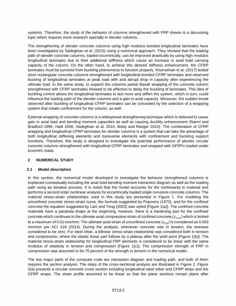
In this section, the numerical model developed to investigate the behavior strengthened columns is
explained conceptually including the axial load-bending moment interaction diagram as well as the loading
path using an iterative process. It is noted that the model accounts for the nonlinearity in material and
performs a second order nonlinear analysis for eccentrically loaded single curvature concrete columns. The
material stress-strain relationships used in this study are presented in Figure 1. For modeling the
unconfined concrete stress-strain curve, the formula suggested by Popovics (1973), and for the confined
concrete the equation suggested by Lam and Teng (2003) was opted [Figure 1(a)]. The confined concrete
materials have a parabola shape at the beginning, however, there is a hardening part for the confined
concrete which continues to the ultimate axial compressive strain of confined concrete (휀𝑐𝑐𝑢) which is limited
to a maximum of 0.01 mm/mm. The ultimate axial strain of unconfined concrete (휀𝑐𝑢) is considered as 0.003
mm/mm per ACI 318 (2014). During the analysis, whenever concrete was in tension, the stresses
considered to be zero. For steel rebar, a bilinear stress-strain relationship was considered both in tension
and compression, where the elastic linear part follows by a plateau after the yield point [Figure 1(b)]. The
material stress-strain relationship for longitudinal FRP elements is considered to be linear with the same
modulus of elasticity in tension and compression [Figure 1(c)]. The compression strength of FRP in
compression was assumed to be 75 percent of the strength in tension in the numerical model.
The two major parts of the computer code are interaction diagram and loading path, and both of them
requires the section analysis. The steps of the cross-sectional analysis are illustrated in Figure 2. Figure
2(a) presents a circular concrete cross section including longitudinal steel rebar and CFRP strips and the
GFRP wraps. The strain profile assumed to be linear so that the plane sections remain plane after

ST13-3
deformations and the strain remains compatible between each two adjacent fibers in a section [Figure 2(b)].
By assuming that the strain profile is determined, the stresses corresponding to each fiber can be found
using the defined material relationships, and in turn by integration of these stresses over the area, the
internal forces are determined [Figure 2(c)]. Then, the equilibrium between the internal and external forces
of the section must be satisfied to check the validity of the strain profile assumption, and the strain profile
must be adjusted for a defined axial load and an initial load eccentricity.
Figure 1: Material relationships: (a) unconfined and confined concrete; (b) steel; (c) FRP
Figure 2: Mechanism of cross sectional analysis: (a) cross section; (b) strain profile; (c) force Diagram
To build the interaction diagram for a steel reinforced concrete column strengthened with longitudinal CFRP
and wrapped with lateral GFRP, both unconfined and confined interaction diagrams are required. To find
the unconfined interaction diagram, the strain at the ultimate compression fiber in the section must be equal
to the ultimate axial strain of unconfined concrete (휀𝑐𝑢). Then, a sectional analysis must be performed by
changing the depth of neutral axis [Figure 2(c)] to satisfy the equilibrium as well as finding the corresponding
axial load and bending moments. The same procedure would be followed for the confined concrete, by
using the confined concrete stress-strain relationship and setting the strain at the maximum compressive
fiber to the ultimate axial compressive strain of confined concrete (휀𝑐𝑐𝑢). Once both confined and
unconfined interaction diagrams are built, the combination of them produce the hybrid interaction diagram
shown in Figure 3. Below the balance point of the confined concrete interaction diagram (where is called
tension-controlled side in which the axial load is low while there are large eccentricities), the unconfined
concrete is selected as hybrid interaction diagram while above that point the confined concrete was
selected. Per ACI 440.2R (2017), the transition between the confined and unconfined interaction diagrams
(b) (c)
steel FRP
(a)
Confined concrete
Hardening
Unconfined concrete
휀𝑐𝑐𝑢휀𝑐𝑢휀𝑜𝜺
𝜺 𝜺𝑓′𝑐
𝝈𝝈 𝝈
𝑓′𝑐𝑐
휀𝑦
𝑓𝑦
𝑓𝑦
휀𝑦
Tension
Compression
Tension
CompressionCompression
𝑓𝑓𝑡𝑢
𝑓𝑓𝑐𝑢
휀𝑓𝑡𝑢
휀𝑓𝑐𝑢
(a)
Cross section
steel rebar
CFRPstrip
GFRPwrap
(b)
Strain profile
(c)
Force Diagram
휀𝑓1휀𝑓2
휀𝑓3휀𝑓4
휀𝑠1
휀𝑠2
𝑑𝑠1
𝑑𝑠2
𝑑𝑓1
𝑑𝑓2
𝑑𝑓3
𝑑𝑓4
𝐷
𝐶
𝑁. 𝐴.𝐶. 𝐿.
Compression
Tension
𝑃
𝑒
𝐹𝑐
𝐹𝑓1
𝐹𝑠1
𝐹𝑓2

ST13-4
is linear for the sake of simplicity, as shown in Figure 3. Another jump in the interaction diagram is at the
eccentricity-to-diameter ratio of 0.1 at which the guideline (ACI 440.2R 2017) limit the effective strain in the
FRP jacket to 0.004 mm/mm for higher eccentricities. It should be noted that for eccentricity-to-diameter
ratios smaller than 0.1, the effective strain in the FRP jacket was considered as 55 percent of ultimate
rupture strain of FRP in the hoop direction. As shown in Figure 3, the maximum allowable capacity of the
column is considered as 80 percent of the ultimate axial column capacity when ties are used as transverse
reinforcement, and 85 percent for the cases where spirals are used. The next part of the discussion
dedicates to a proper algorithm for finding the loading path of the column which performs by changing the
values of the load from zero up to the load at which the loading path intersects with interaction diagram.
Figure 3: Schematic interaction diagram of FRP-wrapped concrete columns per ACI 440.2R (2017)
Figure 4 illustrates the procedure used to find the loading path of the column using an iterative process,
where similar approach used in the literature (Khorramian and Sadeghian 2017, Jiang and Teng 2012).
The column is divided to a number of nodes along the length of the column and these nodes are allowed
to move in the lateral direction. The boundary condition selected as pin-pin which allows the rotation of first
and last node whiel their displacement must be zero. The initial eccentricity (𝑒0), is the same for both ends
to create the single curvature displacement profile. The main relationship in this process is considering the
curvature fuction as the second derivative of the deflection of the column which leads to a relationship
between desired displacement (𝛿𝑖+1) to the the displacement in the two other nodes displacement (𝛿𝑖 , 𝛿𝑖−1 )
and the curvature at the adjacent node (𝜓𝑖+1) as presented in Figure 4. For using this relationship at each
load step, two displacements are required for each nodes at every iteration. The displacement of the first
node is set to zero to satisfy the first boundary condition, and the displacement of the second node is
assumed so that the displacement of third node can be found requireing the curvature, which is derived
from the moment-curvature diagram.
In the kth load step, the moment at ith node (𝑀𝑖) is considered as the product of load (𝑃𝑘) and a summation
of initial eccentricity and nodel displacement (𝑒𝑖 + 𝛿𝑖). This moment is used as an input into the moment
curvature diagram whose output is the curvature at the desired node. It should be noted that the moment
curvature diagram is different for each load step. It can be determined by applying the same concept of
using the section analysis as explained earlier (i.e. by changing the strain at the furthest compressive fiber
and finding the depth of neutral axis which leads to equilibrium satisfaction for a set of predefined load and
eccentricities). The mentioned process for finding the displacement at the third node is repeated to find the
𝑃𝑛
Balance point
e/D = 0.1
0.8𝑃𝑛
휀𝑐𝑐𝑢
Uniformcompression
(Moment resistance)
(Axia
l lo
ad r
esis
tance)
𝑀𝑛
휀𝑐𝑐𝑢
휀𝑐𝑐𝑢
휀𝑐𝑐𝑢
휀𝑦
휀𝑐𝑢
Transition
Unconfined
Confined

ST13-5
displacement of all nodes. Then, the controlling condition is the satisfaction of the second boundary
condition at the the other end of the column. If the displacement of the last node (𝛿𝑛) is close to zero, the
displacements which were found at current load step are accepted, otherwise, the second nodal
displacement is adjusted via an iteration so that the boundary condition of node n is satisfied. Afterwards,
the whole process would be repeated for different load steps to build the complete loading path. Figure 5
presents the monitoring picture of the iterative process during the run of the program.
Figure 4: Iterative process algorithm for stablishing the loading path of slender columns
Figure 5: A view of the monitoring screen of the computer model in MATLAB
Dividing column into n nodes
Set the displacement of thefirst node to zero (𝛿1 = 0)
Assume the displacement of the second node (𝛿2)
Find the displacement of all nodes
𝛿𝑖+1 = 2𝛿𝑖 − 𝛿𝑖−1 + 𝜓𝑖
𝑀1 = 𝑃𝑘(𝑒0 + 𝛿1)
𝑀𝑖 = 𝑃𝑘(𝑒0 + 𝛿𝑖)
Check boundary condition satisfaction at node n (𝛿𝑛 = 0)
Moment curvature diagram at the kth load step (𝑀 − 𝜓)𝑘
𝑀1 → 𝜓1
𝑀𝑖 → 𝜓𝑖
𝛿𝑛 < 10−3𝑚𝑚
The displacements are found in kth load step
𝑌𝑒𝑠
Modify 𝛿2
𝑁𝑜
𝑃𝑒0
𝑒0 𝑃
𝐿
𝛿2
𝛿1 = 0
𝛿𝑛 𝛿𝑛 = 0𝛿𝑛
𝑖𝑡𝑒𝑟𝑎𝑡𝑖𝑜𝑛
𝛿2
𝛿𝑘

ST13-6
There is a certain point in the analysis that is corresponding to the beginning of the descending branch of
the loading path which is defined in a certain load step as the point at which the bending moments (due to
displacement and initial eccentricity) are higher than the maximum moment capacity of the moment-
curvature of the section at that load step. it should be noted that by approaching to this point, the load steps
must be reduced enough up to find the peak load. After the peak load, a descending branch might exist for
the loading path if stability failure happens prior to material failure (i.e. slender columns or highly eccentric
columns). To derive that part, the same procedure can be repeated by starting from the peak load and
decreasing the load in some load steps and using iterative process. One critical key that makes this
algorithm unique and different from other available approaches is that no displacement control approach is
used in the descending branch. Instead, the curvature is controlled at each point to be higher than the
curvature values experienced during the previous step which leads to a drastic run time reduction in
comparison to displacement control approach.
2.2 Model verification
The model is verified for steel reinforced concrete columns confined with CFRP wraps tested by Tao et al.
(2004) and modeled numerically by Jiang and Teng (2012). It should be noted that there is no test data for
the hybrid system proposed in this paper for the developed code to be verified against. The tests were
designed to consider the effects of FRP confinement on slender columns under eccentric loading by
considering two slenderness ratios of 33.6 and 81.6 and four eccentricities of 0, 50, 100, and 150 mm. The
concrete cross section was circular with a diameter of 150 mm where reinforced with four steel rebars with
a diameter of 12 mm. To provide the specimens with confinement, one layer of CFRP wrap with a thickness,
modulus of elasticity, and rupture hoop strain of 0.34mm, 255 GPa, and 0.0167mm/mm, respectively, was
applied on the concrete surface. The verified load-displacement curve of the wrapped columns is shown in
Figure 6. It should be noted that Jiang and Teng considered 7.5 mm additional eccentricity for FRP-confined
specimens which was confirmed in an internal report by the same research group (Yu et al. 2004) and was
considered in this verification as well. The graphs show a very goo agreement with experimental results,
as well as Jiang and Teng theoretical model (Jiang and Teng 2012). As it can be seen in Figure 6, the
model cannot predict large displacements as well as Jiang and Teng (2012) model can predict. The reason
for latter issue is that the stress-strain curve used in this paper was adapted from ACI 440.2R (2017) which
limits the strains to the larger value of 0.01 mm/mm and the maximum confined strain suggested by Lam
and Teng (2003) in addition to limiting the hoop strain to 0.004 mm/mm for eccentricity-to-diameter ratios
that are greater than 0.1 while Jiang and Teng (2012) used a refined confinement model (Teng et al. 2009).
However, this issue does not have any effect of stiffness and strength prediction of the model.
Figure 6: Verification of the model (current study) ageist the test data by Tao et al. (2004) and the model
by Jiang and Teng (2012): (a) medium slenderness ratio, and (b) high slenderness ratio
0
50
100
150
200
250
300
0 10 20 30 40 50 60
Axia
l Load
(kN
)
Lateral Displacemet (mm)
Tao et al. (2004)
Jiang and Teng (2012)
Model
𝜆 = 33.6
Τ𝑒 𝐷 =1
3Τ𝑒 𝐷 =
2
3
Τ𝑒 𝐷 = 10
30
60
90
120
150
0 50 100 150 200 250
Axia
l Load (
kN
)
Lateral Displacemet (mm)
Tao et al. (2004)
Jiang and Teng (2012)
Model
𝜆 = 81.6
Τ𝑒 𝐷 =1
3
Τ𝑒 𝐷 =2
3
Τ𝑒 𝐷 = 1

ST13-7
3 RESULTS AND DISCUSSION
In this section, a steel reinforced circular concrete column (diameter = 250 mm) strengthened with
longitudinal CFRP laminates and wrapped with GFRP wraps was considered. For concrete material, the
strength considered to be 40 MPa while for steel reinforcement the strength and modulus of elasticity were
400 MPa and 200 GPa, respectively. The tensile strength and modulus of elasticity of longitudinal CFRP
were 3267 MPa and 177.8 GPa, respectively. For longitudinal elements, 6-15M steel rebar with a cross
sectional area of 200 mm2 and 32 rectangular CFRP strips with 28.8 mm2 were used to give the
reinforcement ratios of 2.4% and 1.8% for steel rebars and CFRP strips, respectively. For transverse
confining jacket, two layers of GFRP wraps with modulus of elasticity of 32 GPa, design rupture strain of
0.0155 mm/mm, and a nominal thickness of 1 mm for each layer was considered. In the following
subsections the effect of combined longitudinal CFRP and transverse GFRP system, called Hybrid system,
is compared to the control specimen, which includes just reinforcing steel, and with the wrapped system by
considering load eccentricity and slenderness ratio which is followed by a proposed test matrix.
3.1 Parametric study
Figure 7 presents the effect of longitudinal CFRP laminates and GFRP wraps in three load eccentricity-to-
diameter ratios of 0.1, 0.2, and 0.3 while the slenderness ratio was selected as 40 for all specimens. The
interaction diagram shows a huge gain in all load eccentricities for Hybrid specimen in comparison to
confined specimens. As the load eccentricity increases, the loading path tends toward the tension-control
side of interaction diagrams. For e/D = 0.1, the confined specimen increased the capacity of the unconfined
concrete. However, for e/D = 0.2, although the loading path could be continued longer, the code limitations
limit the capacity to the interaction diagram of unconfined concrete while the Hybrid system expand the
loading path due to the presence of longitudinal CFRP elements and intersects the interaction diagram
above the balance point and can still take the advantage of confinement as well. For e/D = 0.3, albeit the
Hybrid system the confinement effect is neglected, the longitudinal CFRP strips increased the unconfined
interaction diagram and caused a considerable strength gain. In the latter case, the GFRP wraps are
necessary to provide the support for the longitudinal CFRP strips and delay their buckling. The same
observation can be seen in Figure 8 where three slenderness ratios of 22, 40, and 60 were examined.
Again, it is observed that the confined specimens in high slenderness ratios are not effective due to
interaction limitation while the interaction and loading path characteristics of Hybrid specimens considerably
improved by adding the longitudinal CFRP strips.
Figure 7: The effect of load eccentricities on performance of RC columns strengthened with wrapping
system and proposed hybrid system
0
1
2
3
4
0 50 100 150
Axia
l L
oad
(M
N)
Moment (kN-m)
Hybrid
Wrapped
RC
𝑒/𝐷 = 0.1
𝜆 = 40
0
1
2
3
4
0 50 100 150
Axia
l L
oad
(M
N)
Moment (kN-m)
Hybrid
Wrapped
RC
𝑒/𝐷 = 0.2𝜆 = 40
0
1
2
3
4
0 50 100 150
Axia
l L
oad
(M
N)
Moment (kN-m)
Hybrid
Wrapped
RC
𝑒/𝐷 = 0.3
Allowed
𝜆 = 40

ST13-8
Figure 8: The effect of slenderness ratios on performance of RC columns strengthened with wrapping
system and proposed hybrid system
3.2 Proposed test matrix
Since this paper recognized the proposed hybrid system as an effective system for gain in strength and
there is no test data available in the literature for this system, this paper proposes a test matrix to be
considered for a comprehensive experimental as presented in Table 1.
Table 1: Proposed experimental test matrix
No. Specimen
ID
Longitudinal reinforcement GFRP Wrapping
ρ (%) λ e/D Reinforcement
code Steel CFRP
1 W1 6-15M - 2 layers - 22 0.2 Wrapped
2 H1 6-15M 32 - 24x1.2 mm 2 layers 1.8 22 0.2 Hybrid
3 W2 6-15M - 2 layers - 40 0.1 Wrapped
4 H2 6-15M 32 - 24x1.2 mm 2 layers 1.8 40 0.1 Hybrid
5 RC 6-15M - - - 40 0.2 Control
6 W3 6-15M - 2 layers - 40 0.2 Wrapped
7 H3 6-15M 16 - 24x1.2 mm 2 layers 0.9 40 0.2 Hybrid
8 H4 6-15M 32 - 24x1.2 mm 2 layers 1.8 40 0.2 Hybrid
9 H5 6-15M 32 - 24x1.2 mm 2 layers 1.8 40 0.3 Hybrid
10 H6 6-15M 32 - 24x1.2 mm 2 layers 1.8 60 0.2 Hybrid
Note: λ = slenderness ratio; ρ = longitudinal CFRP reinforcement ratio; e/D = eccentricity ratio
Since the focus of this proposed test matrix is to investigate the effect of combined longitudinal and
transverse strengthening experimentally, most of the suggested columns are hybrid. Three different load
eccentricity-to-diameter ratios of 0.1, 0.2, and 0.3 as well as three slenderness ratios of 22,40, and 60 with
two different longitudinal CFRP reinforcement ratios of 1.8% and 0.9% are proposed. However, most of the
specimens are built with the slenderness ratio of 22 and with the load eccentricity-to-diameter ratio of 0.2
because of the results of the parametric study that showed this values as the most distinguishing values.
0
1
2
3
4
0 50 100 150
Axia
l L
oad
(M
N)
Moment (kN-m)
Hybrid
Wrapped
RC
𝜆 = 22𝑒/𝐷 = 0.2
0
1
2
3
4
0 50 100 150A
xia
l L
oad
(M
N)
Moment (kN-m)
Hybrid
Wrapped
RC
𝜆 = 40𝑒/𝐷 = 0.2
0
1
2
3
4
0 50 100 150
Axia
l L
oad
(M
N)
Moment (kN-m)
Hybrid
Wrapped
RC
𝜆 = 60
Allowed
𝑒/𝐷 = 0.2

ST13-9
3.3 Proposed test set-up
The proposed test set-up is shown in Figure 9. The concrete column is eccentric compression loading which
is provided by two “Pin” as shown in the Figure 9. The “Pin” includes two steel plates and an steel cylinder
in between is free to rotate and provide the pin-pin boundary conditions. The whole system is supported by
two supports that can be made of concrete or steel and can be designed for the ultimate capacity of the
actuator. In addition, a “Guide” must be designed to make sure that the stroke travels properly and to
minimize the accidental eccentricities. For instrumentation, the mid-height lateral deflection of the column
can be obtained using proper measurement devices. It is useful to install strain gauges on longitudinal
CFRP strips, steel bars, and on the hoop direction of the GFRP wraps.
Figure 9: Proposed set-up for testing large-scale slender RC columns strengthened with the hybrid FRP
system
4 CONCLUSION
This paper investigated the potential of a new hybrid strengthening system consisted of longitudinal
prefabricated CFRP laminates and transverse GFRP wraps externally applied on circular steel-reinforced
concrete columns. An analytical-numerical model was developed considering the nonlinearity in materials
and second-order effects. The model was verified against the experimental test data for a set of test data
on slender concrete columns wrapped with FRPs. However, there is no experimental test data for the hybrid
system. A parametric study performed using the model proposed in this study to evaluate the effectiveness
of the hybrid system by variation of slenderness ratio and load eccentricity. It was observed that the hybrid
system increased the load carrying capacity of slender columns in all cases much more than the wrapping
system. The GFRP wrapping was assumed to control the buckling of the longitudinal CFRP laminates as
well as functioning as a confinement element. The effectiveness of the proposed hybrid system needs to
be verified against test data. A test matrix was proposed to be studied in an experimental program. The
authors are establishing an advance testing setup at Dalhousie University to perform the experimental
program in the near future. It should be noted that the current research is performed for circular cross
section and for rectangular cross sections, more studies are required specially on the combination of
confinement effect and longitudinal CFRP reinforcing elements.
ACKNOWLEDGEMENT
The authors are grateful for the financial support of the Natural Sciences and Engineering Research
Council of Canada (NSERC) and Dalhousie University in conducting this study.
Slender concrete column
Actuator
Load cell
Swivel
Support
Guide
Column cross-section
Support
Strong floor
250 mm
tie (d=6mm)
Longitudinal CFRPlaminates
6-15M
GFRP wrap
Pin
Pin

ST13-10
REFERENCES
ACI 318-14, 2014. Building Code Requirements for Structural Concrete, Farmington Hills, MI: American Concrete Institute.
ACI 440.1R., 2015. Guide for the Design and Construction of Structural Concrete Reinforced Fiber-Reinforced Polymer (FRP) Bars, Farmington Hills, MI: American Concrete Institute.
ACI 440.2R, 2017. Guide for the Design and Construction of Externally Bonded FRP Systems for Strengthening Concrete Structures, Farmington Hills, MI: American Concrete Institute.
Ashour, A. F., El-Refaie, S. A. and Garrity, S. W., 2004. Flexural strengthening of RC continuous beams using CFRP laminates. Cement and concrete composites, 26(7): 765-775.
Bisby, L. and Ranger, M., 2010. Axial–flexural interaction in circular FRP-confined reinforced concrete columns. Construction and Building Materials, 24(9): 1672-1681.
CAN/CSA S806-12, 2012. Design and construction of building structures with fibre-reinforced polymers, s.l.: Canadian Standards Association.
Fillmore, B. and Sadeghian, P., 2018. Contribution of Longitudinal Glass Fiber-Reinforce Polymer Bars in Concrete Cylinders under Axial Compression. Canadian Journal of Civil Engineering, NRC Research Press, 45 (6): 458-468.
Gajdosova, . K. and Bilcik, J., 2013. Full-scale testing of CFRP-strengthened slender reinforced concrete columns. Journal of Composites for Construction 17(2): 239-248.
Hadi, M. N. S., 2006. Behaviour of FRP wrapped normal strength concrete columns under eccentric loading. Composite Structures, 72(4): 503-511.
Jiang, T. and Teng, J. G., 2012. Theoretical model for slender FRP-confined circular RC columns. Construction and building materials, 32: 66-76.
Khorramian, K. and Sadeghian, P., 2017. Experimental and analytical behavior of short concrete columns reinforced with GFRP bars under eccentric loading. Engineering Structures, 151: 761–773.
Khorramian, K. and Sadeghian, P., 2017. Strengthening Concrete Columns using NSM CFRP Laminates, Sixth Asia-Pasific Conference on FRP in Structures, Singapore.
Khorramian, K. and Sadeghian, P., 2017. Strengthening Short Concrete Columns Using Longitudinally Bonded CFRP Laminates, FRPRCS-13 conference and ACI special publication. California, USA, ACI.
Lam, L. and Teng, J. G., 2003. Design-oriented stress–strain model for FRP-confined concrete. Construction and building materials, 6: 471-489.
Mohamed, H. M., Afifi, M. Z. and Benmokrane, B., 2014. Performance Evaluation of Concrete Columns Reinforced Longitudinally with FRP Bars and Confined with FRP Hoops and Spirals under Axial Load. Journal of Bridge Engineering, 19(7): 04014020.
Nanni, A. and Bradford , N., 1995. FRP jacketed concrete under uniaxial compression. Construction and Building Materials, 9(2):115-124.
Popovics, S., 1973. A numerical approach to the complete stress-strain curve of concrete. Cement and concrete research, 3(5): 583-599.
Sadeghian, P. and Fam, A., 2015. Strengthening slender reinforced concrete columns using high-modulus bonded longitudinal reinforcement for buckling control. Journal of structural Engineering, 141:04014127.
Sadeghian, P., Rahai, A. R. and Ehsani, M. R., 2010. Experimental study of rectangular RC columns strengthened with CFRP composites under eccentric loading. Journal of Composites for Construction, 14(4): 443-450.
Shahawy, M., Arockiasamy, M., Beitelman, T. and Sowrirajan, R., 1996. Reinforced concrete rectangular beams strengthened with CFRP laminates. Composites Part B: Engineering, 27(4): 225-233.
Tao, Z., Teng, J. G. , Han, L.H. and Lam., L., 2004. Experimental behaviour of FRP-confined slender RC columns under eccentric loading. Advanced Polymer Composites for Structural Applications in Construction. Guildford, UK: 203-212.
Teng, J. G., Jiang, T., Lam, L. and Luo., Y. Z., 2009. Refinement of a design-oriented stress–strain model for FRP-confined concrete. Journal of Composites for Construction, ASCE,13(4): 269-278.
Tobbi, H., Farghaly, A. S. and Benmokrane, B., 2012. Concrete columns reinforced longitudinally and transversally with glass fiber-reinforced polymer bars. ACI Structural Journal, 109(4): 551-558.
Yu, Q., Tao, Z., Gao, X., Yang, YF., Han, LH., and Zhuang, JP., 2004. Research on seismic performance of FRP-confined RC columns with high axial load ratios,. China: Fuzhou University.