STRENGTHENING R/C COLUMNS BY JACKETING using …library.iugaza.edu.ps/thesis/112842.pdf · m.sc....
103
Transcript of STRENGTHENING R/C COLUMNS BY JACKETING using …library.iugaza.edu.ps/thesis/112842.pdf · m.sc....

M.SC. THESIS
STRENGTHENING OF SQUARE REINFORCED CONCRETE COLUMNS
WITH FIBROUS ULTRA HIGH PERFORMANCE SELF-COMPACTING
CONCRETE JACKETING
داء، ذاتية الدمك عمدة الخرسانية المسلحة مربعة المقطع بعمل قمصان مصنعة من خرسانة عالية األتقوية األ
بروبلينلياف البوليومدعمة بأ
Researcher
ZAKARIA H. HELLES
Supervisors
DR. MOHAMMED ARAFA DR. MAMOUN ALQEDRA
A Thesis Submitted in Partial Fulfillment of the Requirements for the Master
Degree in Design and Rehabilitation of Structures at the Islamic University
Gaza
MARCH, 2014
The Islamic University Gaza
Higher Education Deanship
Faculty of Engineering
Civil Engineering Department
Design and Rehabilitation of
Structures
الجـــــــامعة االســـــالمية بـغزة
عمادة الدراســـــات العليــــــــــا
كليــــــــــــــــة الهندســـــــــــــة
قســـــم الهندســـــــة المدنيـــــة
تآبرنامج تصميم وتأهيل المنشـ


II
ABSTRACT
In recent years, researches have been increasing towards studying the strengthening of
concrete structures using different methods. Various studies have shown that structural
concrete members such as square reinforced concrete (RC) columns can experience a
significant increase in the ultimate load carrying capacity and ductility when
strengthened by a concrete jacket. Despite the large number of performed studies, most
of them did not consider the application of fibrous ultra high performance self-
compacting concrete as a jacketing material. This study aimed at investigating the
effectiveness of strengthening the entire height of downscaled square RC columns by
applying Forta Ferro Polypropylene Fibrous Ultra High Performance Self Compacting
Concrete (Fibrous UHPSCC) as a jacketing material.
The experimental work included the fabrication of three identical unjacketed reference
columns (UC) having similar cross sections of 100×100mm and 300mm high. Nine
monolithically cast reference columns (MC) were fabricated having three cross
sections of 150×150, 160×160, 170×170 mm and 300mm high. The UC and MC
reference columns were made of normal strength concrete (NSC). A total of 27 identical
column cores were made of NSC having similar cross sections of 100×100mm and
300mm high. The four sides of the 27 column cores were strengthened by applying
three jacketing styles with three jacket thicknesses namely; 25, 30 and 35 mm.
The applied three jacketing styles in this study were; Group1 (G1) consisted of nine
column cores jacketed by Fibrous UHPSCC without steel reinforcement, Group2 (G2)
consisted of nine column cores jacketed by Non-Fibrous UHPSCC with steel
reinforcement, and Group3 (G3) consisted of nine column cores jacketed by Fibrous
UHPSCC with steel reinforcement. All the fabricated column specimens were tested
under monotonic uniaxial compression loading in order to investigate the ultimate load
carrying capacity, longitudinal axial strain and failure pattern.
A comparative study was performed between the jacketed column specimens and the
reference columns. The G1, G2 and G3 jacketed column specimens showed significant
increase in the ultimate load carrying capacity higher about 4.4 times than the UC
reference column, and higher about 2.1 times than the MC reference columns
respectively. The measured longitudinal axial strain of G1 and G3 jacketed column
specimens was higher about 2.1 and 2.3 times than that of UC and MC reference
columns respectively. Whereas the longitudinal axial strain of G2 jacketed column
specimens was reduced by about 27% less than that of UC and MC reference columns.
The results also revealed that the failure patterns and crack formation were significantly
influenced by both the jacketing thickness and the jacketing style.
III
ARABIC ABSTRACT ثظشأ. لذ سخخذا طشق عذةإب اخشسايت اشآث صالحإ حميت خيشةفي اآلت األاذساساث حاج اعذيذ
لة صادث والخشسايت لذ امصا ابعذة اخشسايت شبعت امطع أ حميت األاعذيذ ز اذساساث
أجشيج عى اخي ثذساسا اعذد اىبيشاشغ عى طيخا عى اساء. سيتأداي اشأل عذةحذ األ
سن األ عذة اخشسايت ا عذة اخشسايت بع حميت األ عخباسحضع في األ ز اذسساث غبأفإ ،تيم
بي.شياف ابيباألداء، راحيت اذه ذعت بؤخشسات عايت لصا صعت
عياث اىي طيابخغيف شبعت امطعا اسذت عذة اخشسايتحميت األوفاءة دساست ابذث از حايديث
.ابيبشبيياف ؤداء، راحيت اذه ذعت بشسايت صعت خشسات عايت األخ مصابعذة األ
تشبع تسذ( غيش ميت تشجعيعذة أ) (UC)تخشساي ةعذأ ثالثتصب عى اعيت اذساست شخجإ لذ
ح صبا وىخت شجعيتعذة أ) (MC) عذة خشسايتأ، صب حسعت 011اسحفاع ب 011×011امطع
أسخخذج اخشسات . 011سحفاع إب 071×071، 011×011، 011×011 ( سذت شبعت امطعادذة
. UC MC اشجعيتاعاديت صب جيع األعذة اخشسايت
011×011عد خشساي سخ شبع امطع 77صب ا جع أسخخذج اخشسات اعاديت في وا
خشسايت امصا ا حطبيك ثالثت حمياث ع ع طشيك جاب األسبعت حغيف، ره بغشض 011سحفاع إب
.01، 01، 71 ي ساواثبثالثت
اخي ح G1ى األاألعذة خالي ز اذساست ي جعتمذ ح حطبيك ثالثت حمياث ع امصا اخشسايت
ضافت دذيذ إياف ابيبشبي ع عذ صا خشسايت خشسات عايت األداء ذعت بؤعذحا بع لأحميت
صا خشسايت خشسات عذحا بع لأاخي ح حميت G2اثايت األعذة جعت حسيخ ميص اخشساي،
اثاثت األعذة جعت ضافت دذيذ حسيخ ميص اخشساي، عايت األداء غيش ذعت بؤياف ابيبشبي ع إ
G3 ضافت داء ذعت بؤياف ابيبشبي ع إيت خشسات عايت األعذحا بع لصا خشساأاخي ح حميت
دذيذ حسيخ ميص اخشساي.
ره عى شوض اعد خساجضغظ سأسي د بخطبيك في اخخبش اخشسايتاألعذة عياث فذص جيع ح
حجا اخذي إفي األعذة يت طسيت، أداي اشذ األح فياألعذة بمةبذف اذصي عى اخائج اخعمت
طبيعت شى االياس.
ظشث أديث اشجعيت.األعذة خائج ع عذة اميتأل اعيت اخي ح اذصي عيا خائج ماست جشيجأث
ضعاف أ 4.4 حعادي وسش اعدلذ دصج عى صيادة وبيشة في لة G1 ،G2 G3جعاث ا عذةأ أاخائج
UCاشجعيت األعذة لة وسش G1 ،G2 G3 عذة اجعاثأوا واج اضيادة في لة وسش . ميتاغيش
اخي ح صبا وىخت ادذة.MC اشجعيتاألعذة لة وسشضعف 2.1حعادي
ضغاطإلاألعذة حذ لذسة ا صاد G1 G3 اجعخي عذةأ صيادة ذظت في طيت ججوا س
عى UC MC اشجعيتاألعذة طيت ضعاف أ 7.0 7 يعاديواج اضيادة في اطيت با سيأشا
اشجعيت.األعذة طيت % 77 مذاسب لأ G2 تجععذة اأطيت ج ، في دي وااخاي
امصا اخشسايت ساوت ى بثيشا وبيشا ؤحيخاثشا اخشمماث طبيعتياس أ شى اإليضا أظشث اخائج ألذ
يت اسخخذت في اخميت.اآلوزه
IV
DEDICATION
I would like to dedicate this work to my family specially my mother who loved and
raised me and to the soul of my father who wished me this success, to my loving wife
and daughter and to my brothers and sisters, for their sacrifice and endless support and
to whom I belong.

V
ACKNOWLEDGMENT
I would like to express my sincere appreciation to Dr. Mohammed Arafa and Dr.
Mamoun Alqedra from the Department of Civil Engineering at The Islamic University
of Gaza, for their help, guidance and assistance in all stages of this research. The
constant encouragement, support and inspiration they offered were fundamental to the
completion of this research.
Special thanks go to the Material and Soil Laboratory of the Islamic University-Gaza,
for their logistic facilitations and their continuous support as well as to all my lecturers
from whom I learned much and developed my skills.
I would like to express my deep thanks for my brothers and friends for their assistance
during the practical work of the research.
Finally I would like to thank everyone who gave advice or assistance that contributed to
complete this research.
VI
TABLE OF CONTENTS
ABSTRACT ----------------------------------------------------------------------------------------------------------- II
ARABIC ABSTRACT --------------------------------------------------------------------------------------------- III
DEDICATION ------------------------------------------------------------------------------------------------------- IV
ACKNOWLEDGMENT -------------------------------------------------------------------------------------------- V
TABLE OF CONTENTS ------------------------------------------------------------------------------------------ VI
LIST OF TABLES -------------------------------------------------------------------------------------------------- IX
LIST OF FIGURES ------------------------------------------------------------------------------------------------- X
NOTATIONS ------------------------------------------------------------------------------------------------------- XII
INTRODUCTION --------------------------------------------------------------------------------- 1 CHAPTER 1 -
1.1. INTRODUCTION ----------------------------------------------------------------------------------------------------- 2
1.2. PROBLEM STATEMENT --------------------------------------------------------------------------------------------- 3
1.3. RESEARCH OBJECTIVES ------------------------------------------------------------------------------------------- 4
1.4. METHODOLOGY ---------------------------------------------------------------------------------------------------- 4
1.5. THESIS LAYOUT ---------------------------------------------------------------------------------------------------- 5
LITERATURE REVIEW ------------------------------------------------------------------------ 7 CHAPTER 2 -
2.1. INTRODUCTION ----------------------------------------------------------------------------------------------------- 8
2.2. STRENGTHENING TECHNIQUES OF RC COLUMNS ------------------------------------------------------------- 8
Jacketing RC Columns using Steel Profile -------------------------------------------------------------- 8 2.2.1.
Jacketing RC Columns by External Steel Battens Welded to Steel Angles ------------------------ 9 2.2.2.
Jacketing RC Columns by FRP -------------------------------------------------------------------------- 11 2.2.3.
Strengthening RC Columns by Concrete Jacketing -------------------------------------------------- 13 2.2.4.
2.3. FIBROUS ULTRA HIGH PERFORMANCE SELF-COMPACTING CONCRETE --------------------------------- 22
Ultra-High Performance Concrete (UHPC) ------------------------------------------------------------ 22 2.3.1.
Self-Compacting Concrete (SCC) ----------------------------------------------------------------------- 22 2.3.2.
The Developing History of UHPSCC------------------------------------------------------------------ 23 2.3.3.
Types of Fibers -------------------------------------------------------------------------------------------- 23 2.3.4.
Polypropylene Fibers ------------------------------------------------------------------------------------------- 24 2.3.4.1.
Forta Ferro Polypropylene Fibers ----------------------------------------------------------------------------- 25 2.3.4.2.
2.4. PROPERTIES OF FIBROUS UHPSCC ---------------------------------------------------------------------------- 25
Strength ------------------------------------------------------------------------------------------------------ 25 2.4.1.
Durability ---------------------------------------------------------------------------------------------------- 26 2.4.2.
Workability ------------------------------------------------------------------------------------------------- 26 2.4.3.
Sustainability ----------------------------------------------------------------------------------------------- 27 2.4.4.
Affordability ------------------------------------------------------------------------------------------------ 27 2.4.5.
2.5. SUMMARY OF LITERATURE REVIEW -------------------------------------------------------------------------- 27
EXPERIMENTAL WORK -------------------------------------------------------------------- 29 CHAPTER 3 -
3.1. INTRODUCTION --------------------------------------------------------------------------------------------------- 30
3.2. EXPERIMENTAL PROGRAM -------------------------------------------------------------------------------------- 30
3.3. CATEGORIZING THE COLUMN SPECIMENS ------------------------------------------------------------------- 31
3.4. TYPES OF CONCRETE MIXES ------------------------------------------------------------------------------------ 33
3.5. PREPARATION OF UC, MC REFERENCE COLUMNS AND COLUMN CORES -------------------------------- 33
Properties of NSC Ingredients --------------------------------------------------------------------------- 33 3.5.1.
NSC Mixing Proportions --------------------------------------------------------------------------------- 34 3.5.2.
VII
Properties of Reinforcement Steel ---------------------------------------------------------------------- 34 3.5.3.
Reinforcement Details ------------------------------------------------------------------------------------- 35 3.5.4.
Mixing Procedures ----------------------------------------------------------------------------------------- 35 3.5.5.
Casting of NSC --------------------------------------------------------------------------------------------- 36 3.5.6.
Curing of NSC----------------------------------------------------------------------------------------------- 37 3.5.7.
3.6. PREPARATION OF THE JACKET ---------------------------------------------------------------------------------- 37
Properties of Fibrous UHPSCC -------------------------------------------------------------------------- 37 3.6.1.
Aggregates ------------------------------------------------------------------------------------------------------- 37 3.6.1.1.
Cement ----------------------------------------------------------------------------------------------------------- 38 3.6.1.2.
Mixing Water ---------------------------------------------------------------------------------------------------- 38 3.6.1.3.
Forta-Ferro Polypropylene Fibers (FFP) --------------------------------------------------------------------- 39 3.6.1.4.
Superplasticizer ------------------------------------------------------------------------------------------------- 39 3.6.1.5.
Silica Fume------------------------------------------------------------------------------------------------------- 40 3.6.1.6.
Mixing Proportions of Fibrous and Non-Fibrous UHPSCC ---------------------------------------- 41 3.6.2.
Reinforcement Details ------------------------------------------------------------------------------------- 41 3.6.3.
Mixing Procedures ----------------------------------------------------------------------------------------- 43 3.6.4.
Casting of UHPSCC --------------------------------------------------------------------------------------- 43 3.6.5.
Curing of UHPSCC ------------------------------------------------------------------------------------------ 44 3.6.6.
3.7. TESTING OF COLUMN SPECIMENS------------------------------------------------------------------------------ 44
The Ultimate Load Carrying Capacity of Column Specimens ------------------------------------- 45 3.7.1.
The Longitudinal Axial Strain of Column Specimens ----------------------------------------------- 45 3.7.2.
RESULTS & DISCUSSION ------------------------------------------------------------------- 46 CHAPTER 4 -
4.1. INTRODUCTION --------------------------------------------------------------------------------------------------- 47
4.2. NSC COMPRESSIVE STRENGTH -------------------------------------------------------------------------------- 47
4.3. UHPSCC COMPRESSIVE STRENGTH -------------------------------------------------------------------------- 47
4.4. UC REFERENCE COLUMN --------------------------------------------------------------------------------------- 48
Results of UC Ultimate Load Carrying Capacity ----------------------------------------------------- 48 4.4.1.
Results of UC Longitudinal Axial Strain -------------------------------------------------------------- 48 4.4.2.
4.5. MC REFERENCE COLUMNS ------------------------------------------------------------------------------------- 49
Results of MC Ultimate Load Carrying Capacity ---------------------------------------------------- 49 4.5.1.
Results of MC Longitudinal Axial Strain -------------------------------------------------------------- 51 4.5.2.
4.6. G1 JACKETED COLUMN SPECIMENS --------------------------------------------------------------------------- 53
Effect of Fibrous UHPSCC Unreinforced Jacketing on G1 Ultimate Load Carrying Capacity4.6.1.
------------------------------------------------------------------------------------------------------------------------ 53
Effect of Fibrous UHPSCC Unreinforced Jacketing on G1 Longitudinal Axial Strain -------- 56 4.6.2.
Effect of Fibrous UHPSCC Unreinforced Jacketing on G1 Failure Pattern --------------------- 59 4.6.3.
4.7. G2 JACKETED COLUMN SPECIMENS --------------------------------------------------------------------------- 61
Effect of Non-Fibrous UHPSCC Steel Reinforced Jacketing on G2 Ultimate Load Carrying 4.7.1.
Capacity ------------------------------------------------------------------------------------------------------------- 61
Effect of Non-Fibrous UHPSCC Steel Reinforced Jacketing on G2 Longitudinal Axial Strain4.7.2.
------------------------------------------------------------------------------------------------------------------------ 63
Effect of Non-Fibrous UHPSCC Steel Reinforced Jacketing on G2 Failure Pattern ----------- 67 4.7.3.
4.8. G3 JACKETED COLUMN SPECIMENS --------------------------------------------------------------------------- 68
Effect of Fibrous UHPSCC Steel Reinforced Jacketing on G3 Ultimate Load Carrying 4.8.1.
Capacity ------------------------------------------------------------------------------------------------------------- 68
Effect of Fibrous UHPSCC Steel Reinforced Jacketing on G3 Longitudinal Axial Strain ---- 70 4.8.2.
Effect of Fibrous UHPSCC Steel Reinforced Jacketing on G3 Failure Pattern ----------------- 74 4.8.3.
4.9. ULTIMATE LOAD CARRYING CAPACITY AND AXIAL STRAIN OF G1, G2 AND G3 COLUMNS WITH
RESPECT TO UC AND MC -------------------------------------------------------------------------------------------- 74
CONCLUSIONS & RECOMMENDATIONS --------------------------------------------- 78 CHAPTER 5 -
5.1. INTRODUCTION --------------------------------------------------------------------------------------------------- 79
VIII
5.2. CONCLUSION ------------------------------------------------------------------------------------------------------ 79
5.3. RECOMMENDATIONS --------------------------------------------------------------------------------------------- 81
Findings ------------------------------------------------------------------------------------------------------ 81 5.3.1.
Suggestions ------------------------------------------------------------------------------------------------- 81 5.3.2.
REFERENCES ------------------------------------------------------------------------------------------------------ 82
INDEX ---------------------------------------------------------------------------------------------------------------- 87
IX
LIST OF TABLES
TABLE 2-1: UHPSCC DEVELOPMENT.[32] --------------------------------------------------------------------------- 23
TABLE 2-2: PHYSICAL PROPERTIES OF FORTA FERRO POLYPROPYLENE FIBERS.[4] --------------------------- 25
TABLE 2-3: EFNARC CRITERIA OF SELF-COMPACTING CONCRETE --------------------------------------------- 26
TABLE 3-1: DETAILS OF COLUMN SPECIMENS. ----------------------------------------------------------------------- 33
TABLE 3-2: NSC MIXING PROPORTIONS.[38] ------------------------------------------------------------------------ 34
TABLE 3-3: STEEL REINFORCEMENT TESTING RESULTS. ----------------------------------------------------------- 35
TABLE 3-4: CEMENT PROPERTIES BASED ON MANUFACTURER SHEET. [37] ------------------------------------ 38
TABLE 3-5: PHYSICAL PROPERTIES OF FORTA FERRO POLYPROPYLENE FIBERS.[4] --------------------------- 39
TABLE 3-6: SIKAMENT 163M TECHNICAL DATA.[37] -------------------------------------------------------------- 39
TABLE 3-7: SELF-COMPACTING PROPERTIES OF UHPSCC MIX. -------------------------------------------------- 40
TABLE 3-8: SIKA-FUME PROPERTIES.[37] ----------------------------------------------------------------------------- 40
TABLE 3-9: MIXING PROPORTIONS OF FIBROUS UHPSCC.[35] --------------------------------------------------- 41
TABLE 3-10: DETAILS OF G1, G2 AND G3 JACKETED COLUMN SPECIMENS. ------------------------------------ 41
TABLE 4-1: COMPRESSION TEST RESULTS OF NSC. ----------------------------------------------------------------- 47
TABLE 4-2: COMPRESSION TEST RESULTS OF FIBROUS AND NON-FIBROUS UHPSCC. ----------------------- 47
TABLE 4-3: UC ULTIMATE LOAD CARRYING CAPACITY. ---------------------------------------------------------- 48
TABLE 4-4: MC ULTIMATE LOAD CARRYING CAPACITY. ---------------------------------------------------------- 50
TABLE 4-5: G1 ULTIMATE LOAD CARRYING CAPACITY. ----------------------------------------------------------- 54
TABLE 4-6: INCREASE IN G1 ULTIMATE LOAD CARRYING CAPACITY WITH RESPECT TO UC AND MC. ---- 55
TABLE 4-7: INCREASE IN G1 MAXIMUM LONGITUDINAL AXIAL STRAIN WITH RESPECT TO UC AND MC. - 58
TABLE 4-8: G2 ULTIMATE LOAD CARRYING CAPACITY. ----------------------------------------------------------- 61
TABLE 4-9: INCREASE IN G2 ULTIMATE LOAD CARRYING CAPACITY WITH RESPECT TO UC AND MC. ---- 63
TABLE 4-10: DECREASE IN G2 MAXIMUM LONGITUDINAL AXIAL STRAIN WITH RESPECT TO UC AND MC.
------------------------------------------------------------------------------------------------------------------------ 66
TABLE 4-11: G3 ULTIMATE LOAD CARRYING CAPACITY. --------------------------------------------------------- 68
TABLE 4-12: INCREASE IN G3 ULTIMATE LOAD CARRYING CAPACITY WITH RESPECT TO UC AND MC. -- 69
TABLE 4-13: INCREASE IN G3 MAXIMUM LONGITUDINAL AXIAL STRAIN WITH RESPECT TO UC AND MC. 73
TABLE 4-14: SUMMARY OF THE RESULTS FOR ALL TESTED COLUMN SPECIMENS. ---------------------------- 77

X
LIST OF FIGURES
FIGURE 1-1: RESEARCH METHODOLOGY. ------------------------------------------------------------------------------- 5
FIGURE 2-1: THREE GROUPS LOAD DEFLECTION CURVES. [6] ------------------------------------------------------ 9
FIGURE 2-2: DETAILING OF PLATES AND ANGLES. [7] -------------------------------------------------------------- 10
FIGURE 2-3: CAMPIONE EXPERIMENTAL RESULTS COMPARED WITH OTHER STUDIES. [9] -------------------- 11
FIGURE 2-4: LOAD VS. STRAIN RELATIONSHIP FOR CIRCULAR AND SQUARE COLUMNS. [12] ---------------- 12
FIGURE 2-5: GEOMETRY OF UN-JACKETED, HPFRC JACKETED AND TRADITIONAL JACKETED SECTIONS
FROM LEFT TO RIGHT RESPECTIVELY. [23] -------------------------------------------------------------------- 15
FIGURE 2-6: M-N ENVELOPES FOR THE THREE ANALYZED STRENGTHENING TECHNIQUES. [23] ----------- 15
FIGURE 2-7: GEOMETRIC PROPERTIES AND REINFORCEMENT OF THE FOUR SIDES JACKETED COLUMNS. [24]
------------------------------------------------------------------------------------------------------------------------ 16
FIGURE 2-8: GEOMETRIC PROPERTIES AND REINFORCEMENT OF THE THREE SIDES JACKETED
COLUMNS. [24] ----------------------------------------------------------------------------------------------------- 17
FIGURE 2-9: LOAD–DISPLACEMENT RELATIONSHIPS FOR TESTED SPECIMENS. [25] --------------------------- 18
FIGURE 2-10: CROSS SECTION OF SPECIMENS. [27] ----------------------------------------------------------------- 19
FIGURE 2-11: LOAD-STRAIN CURVES OF COLUMN SPECIMENS.[27] ---------------------------------------------- 19
FIGURE 2-12: GEOMETRY OF CROSS SECTION AND BENT DOWN STEEL CONNECTOR. [28] ------------------- 20
FIGURE 2-13: LOAD AGAINST DISPLACEMENT ENVELOPES FOR ALL SPECIMENS. [28] ------------------------ 21
FIGURE 2-14: TYPES OF FIBERS. ---------------------------------------------------------------------------------------- 23
FIGURE 2-15: POLYPROPYLENE FIBERS.[4] --------------------------------------------------------------------------- 24
FIGURE 2-16: SLUMP FLOW, L-BOX AND V-FUNNEL TESTS. ------------------------------------------------------- 27
FIGURE 3-1: EXPERIMENTAL PROGRAM. ------------------------------------------------------------------------------ 30
FIGURE 3-2: GEOMETRY AND STEEL DETAILS OF UC UNJACKETED REFERENCE COLUMN. ------------------ 31
FIGURE 3-3: GEOMETRY AND STEEL OF MC1 MONOLITHIC CAST REFERENCE COLUMN. -------------------- 32
FIGURE 3-4: MAIN REBAR TENSION TEST. ---------------------------------------------------------------------------- 34
FIGURE 3-5: GEOMETRY AND STEEL DETAILS OF COLUMN CORE. ------------------------------------------------ 35
FIGURE 3-6: HANDLING FRESH NSC MIX FROM MIXING DRUM. ------------------------------------------------- 36
FIGURE 3-7: OILING AND CASTING TIMBER MOULDS. -------------------------------------------------------------- 36
FIGURE 3-8: THE AGGREGATES USED IN UHPSCC MIX. ----------------------------------------------------------- 38
FIGURE 3-9: FORTA-FERRO POLYPROPYLENE FIBERS.[4] ---------------------------------------------------------- 39
FIGURE 3-10: SIKAMENT 163M SUPERPLASTICIZER. ---------------------------------------------------------------- 40
FIGURE 3-11: SILICA FUME APPEARANCE ---------------------------------------------------------------------------- 40
FIGURE 3-12: GEOMETRY AND STEEL DETAILS OF G1-25, G2-25 AND G3-25. --------------------------------- 42
FIGURE 3-13: SHEAR CONNECTORS AND BONDING AGENT. ------------------------------------------------------- 43
FIGURE 3-14: COLUMN CORES LOCATED IN TIMBER MOULDS BEFORE CASTING.------------------------------ 44
FIGURE 3-15: THE COMPRESSION TESTING MACHINE -------------------------------------------------------------- 45
FIGURE 4-1: FAILURE PATTERN OF UC REFERENCE COLUMN. ---------------------------------------------------- 48
FIGURE 4-2: LOAD-STRAIN DIAGRAM OF UC REFERENCE COLUMNS. ------------------------------------------- 49
FIGURE 4-3: AVERAGE LOAD-STRAIN DIAGRAM OF UC REFERENCE COLUMN. -------------------------------- 49
FIGURE 4-4: ULTIMATE LOAD CARRYING CAPACITY OF UC AND MC REFERENCE COLUMNS. -------------- 50
FIGURE 4-5: LOAD-STRAIN DIAGRAM OF MC1 REFERENCE COLUMN. ------------------------------------------- 51
FIGURE 4-6: AVERAGE LOAD-STRAIN DIAGRAM OF MC1 REFERENCE COLUMN. ------------------------------ 51
FIGURE 4-7: LOAD-STRAIN DIAGRAM OF MC2 REFERENCE COLUMN. ------------------------------------------- 51
FIGURE 4-8: AVERAGE LOAD-STRAIN DIAGRAM OF MC2 REFERENCE COLUMN. ------------------------------ 52
FIGURE 4-9: LOAD-STRAIN DIAGRAM OF MC3 REFERENCE COLUMN. ------------------------------------------- 52
FIGURE 4-10: AVERAGE LOAD-STRAIN DIAGRAM OF MC3 REFERENCE COLUMN. ---------------------------- 52
FIGURE 4-11: LOAD-STRAIN DIAGRAMS OF UC, MC1, MC2 AND MC3 REFERENCE COLUMNS. ------------ 53
FIGURE 4-12: G1 ULTIMATE LOAD CARRYING CAPACITY.--------------------------------------------------------- 54
FIGURE 4-13: G1 ULTIMATE LOAD CARRYING CAPACITY WITH RESPECT TO UC AND MC. ------------------ 55
XI
FIGURE 4-14: LOAD-STRAIN DIAGRAM OF G1-25 JACKETED COLUMN SPECIMENS. --------------------------- 56
FIGURE 4-15: AVERAGE LOAD-STRAIN DIAGRAM OF G1-25 JACKETED COLUMN SPECIMENS. -------------- 56
FIGURE 4-16: LOAD-STRAIN DIAGRAM OF G1-30 JACKETED COLUMN SPECIMENS. --------------------------- 56
FIGURE 4-17: AVERAGE LOAD-STRAIN DIAGRAM OF G1-30 JACKETED COLUMN SPECIMENS. -------------- 57
FIGURE 4-18: LOAD-STRAIN DIAGRAM OF G1-35 JACKETED COLUMN SPECIMENS. --------------------------- 57
FIGURE 4-19: AVERAGE LOAD-STRAIN DIAGRAM OF G1-35 JACKETED COLUMN SPECIMENS. -------------- 57
FIGURE 4-20: AVERAGE LOAD-STRAIN DIAGRAM OF G1-25, G1-30 AND G1-35 ------------------------------- 58
FIGURE 4-21: AVERAGE LOAD-STRAIN DIAGRAMS OF G1-25, G1-30, G1-35 WITH RESPECT TO UC AND
MC.------------------------------------------------------------------------------------------------------------------- 59
FIGURE 4-22: FAILURE PATTERN OF UC REFERENCE COLUMN. --------------------------------------------------- 60
FIGURE 4-23: FAILURE PATTERN OF MC REFERENCE COLUMNS. ------------------------------------------------- 60
FIGURE 4-24: FAILURE PATTERN OF G1 JACKETED COLUMN SPECIMENS. -------------------------------------- 61
FIGURE 4-25: G2 ULTIMATE LOAD CARRYING CAPACITY.--------------------------------------------------------- 62
FIGURE 4-26: G2 ULTIMATE LOAD CARRYING CAPACITY WITH RESPECT TO UC AND MC. ------------------ 63
FIGURE 4-27: LOAD-STRAIN DIAGRAM OF G2-25 JACKETED COLUMN SPECIMENS. --------------------------- 64
FIGURE 4-28: AVERAGE LOAD-STRAIN DIAGRAM OF G2-25 JACKETED COLUMN SPECIMENS. -------------- 64
FIGURE 4-29: LOAD-STRAIN DIAGRAM OF G2-30 JACKETED COLUMN SPECIMENS. --------------------------- 64
FIGURE 4-30: AVERAGE LOAD-STRAIN DIAGRAM OF G2-30 JACKETED COLUMN SPECIMENS. -------------- 65
FIGURE 4-31: LOAD-STRAIN DIAGRAM OF G2-35 JACKETED COLUMN SPECIMENS. --------------------------- 65
FIGURE 4-32: AVERAGE LOAD-STRAIN DIAGRAM OF G2-35 JACKETED COLUMN SPECIMENS. -------------- 65
FIGURE 4-33: AVERAGE LOAD-STRAIN DIAGRAM OF G2-25, G2-30 AND G2-35. ------------------------------ 66
FIGURE 4-34: AVERAGE LOAD-STRAIN DIAGRAMS OF G2-25, G2-30, G2-35 WITH RESPECT TO UC AND
MC.------------------------------------------------------------------------------------------------------------------- 67
FIGURE 4-35: FAILURE PATTERN OF G2 JACKETED COLUMN SPECIMENS. -------------------------------------- 67
FIGURE 4-36: G3 ULTIMATE LOAD CARRYING CAPACITY.--------------------------------------------------------- 69
FIGURE 4-37: G3 ULTIMATE LOAD CARRYING CAPACITY WITH RESPECT TO UC AND MC. ------------------ 70
FIGURE 4-38: LOAD-STRAIN DIAGRAM OF G3-25 JACKETED COLUMN SPECIMENS. --------------------------- 70
FIGURE 4-39: AVERAGE LOAD-STRAIN DIAGRAM OF G3-25 JACKETED COLUMN SPECIMENS --------------- 71
FIGURE 4-40: LOAD-STRAIN DIAGRAM OF G3-30 JACKETED COLUMN SPECIMENS ---------------------------- 71
FIGURE 4-41: AVERAGE LOAD-STRAIN DIAGRAM OF G3-30 JACKETED COLUMN SPECIMENS --------------- 71
FIGURE 4-42: LOAD-STRAIN DIAGRAM OF G3-35 JACKETED COLUMN SPECIMENS ---------------------------- 72
FIGURE 4-43: AVERAGE LOAD-STRAIN DIAGRAM OF G3-35 JACKETED COLUMN SPECIMENS --------------- 72
FIGURE 4-44: AVERAGE LOAD-STRAIN DIAGRAM OF G3-25, G3-30 AND G3-35. ------------------------------ 72
FIGURE 4-45: AVERAGE LOAD-STRAIN DIAGRAMS OF G3-25, G3-30, G3-35 WITH RESPECT TO UC AND
MC.------------------------------------------------------------------------------------------------------------------- 73
FIGURE 4-46: FAILURE PATTERN OF G3 JACKETED COLUMN SPECIMENS. -------------------------------------- 74
FIGURE 4-47: G1, G2 AND G3 ULTIMATE LOAD CARRYING CAPACITY WITH RESPECT TO UC AND MC. -- 75
FIGURE 4-48: G1-25, G2-25 AND G3-25 LONGITUDINAL AXIAL STRAIN WITH RESPECT TO UC AND MC1.76
FIGURE 4-49: G1-30, G2-30 AND G3-30 LONGITUDINAL AXIAL STRAIN WITH RESPECT TO UC AND MC2.76
FIGURE 4-50: G1-35, G2-35 AND G3-35 LONGITUDINAL AXIAL STRAIN WITH RESPECT TO UC AND MC3.76
XII
NOTATIONS
ABBREVIATIONS
UHPC Ultra High Performance Concrete
FFP Forta-Ferro Polypropylene
SCC Self-Compacting Concrete
UHPSCC Ultra-High Performance Self-Compacting Concrete
CFRP Carbon Fiber Reinforced Polymer
RC Reinforced Concrete
ACI American Concrete Institute
FRP Fiber Reinforced Polymer
NSC Normal Strength Concrete
ASTM American Society for Testing and Materials
HPFRC High Performance Fiber Reinforced Concrete
HPC High Performance Concrete
W/C Water Cement Ratio
IUG Islamic University-Gaza
KN Kilo Newton
MPa Mega Pascal
NOMENCLATURE
h/b Height to Breadth Ratio
UC Unjacketed Column Specimen(Reference Column)
MC Monolithically Cast Column Specimen (Reference Columns of Three
Cross Sections )
G1 Group of 9 Column Cores Strengthened with Fibrous UHPSCC
Jacket
G2 Group of 9 Column Cores Strengthened with Non-Fibrous UHPSCC
Steel Reinforced Jacket
G3 Group of 9 Column Cores Strengthened with Fibrous UHPSCC Steel
Reinforced Jacket
S Sample of Column specimen
fy Steel Yield Strength
fc’ Compressive Strength of Concrete Standard Cylinder

CHAPTER 1INTRODUCTION

CHAPTER 1 INTRODUCTION
2
1.1. Introduction
Repairing and strengthening of reinforced concrete (RC) elements is required for
several reasons, namely; damages, extension of lifetime and serviceability of structure,
lack of structure maintenance and degradation. Other reasons can be considered like the
retrofitting of the structure to meet the current design codes and regulations. Structural
members may need to be upgraded to current seismic requirements, as existing
structural components may be deficient in terms of seismic strength which can be
attributed to an inadequate transverse steel reinforcement. Strengthening such elements
is a method to increase the flexural, axial and shear strengths.[1, 6 and 7]
Strengthening methods depend on the type of the structure and loading, as for structures
subjected mainly to static load, increasing flexural and axial compressive strength is
more considerable, and for structures subjected mainly to dynamic load, increasing
flexural and shear strength is more considerable. Improving column ductility and
rearrangement of column stiffness can also be achieved by strengthening. Damages to
RC columns may include slight cracks without damages to reinforcement, superficial
damage in concrete without damage to reinforcement, concrete crushing, reinforcement
buckling or ties rupture. Based on the degree of damage, techniques such as injections,
removal and replacement or jacketing can be applied. [7, 9, 22 and 23]
Five commonly jacketing techniques are used for strengthening the RC columns in
construction:
1) Concrete jacketing;
2) Steel jacketing;
3) Jacketing by Composite Materials (Carbon Fiber Reinforced Polymer CFRP);
4) Precast Concrete Jacketing;
5) External Pre-stressing Jacketing using Steel Strands;
Ultra High Performance Concrete (UHPC) is being considered for use in a wide variety
of mega structure applications. The high compressive and tensile strength allow for the
redesign and optimization of structural elements. Concurrently, the enhanced durability
properties facilitate a lengthening of design life and allow for potential use as thin
overlays, claddings, repairing and jacketing of columns.[2, 3, 23 and 26]
Despite UHPC has very high compressive strength, it shows very brittle failure behavior
compared to the Normal Strength Concrete (NSC). The UHPC ductility and fracture
brittleness can be improved by adding fibers, so the addition of fibers in producing
UHPC will add innovative features to the structures and open new areas of UHPC
applications.[3, 26, 35 and 37]
CHAPTER 1 INTRODUCTION
3
During the last two decades, increased productivity and improved working environment
have had high priority in the development of concrete construction, so there is another
new concrete produced which is Self-Compacting Concrete (SCC). The main goal
behind the rapid growing of SCC is the easiness in placement and casting in heavily
reinforced and inaccessible areas. In addition, SCC increases productivity levels leading
to shortened concrete construction time and reducing the effort of concrete compacting
which leads to reduction in honeycombing and segregation problems.[3, 35 and 37]
The addition of fibers reduced plastic and hardened concrete shrinkage, improves
impact strength, increases both fatigue resistance and toughness of the UHPSCC.
Moreover it greatly improves the tensile strength of the UHPSCC as well as the
ductility.[4, 34 and 36]
This research will study the strengthening of square RC columns by applying three
concrete jacketing styles using Forta Ferro Polypropylene Fibrous Ultra High
Performance Self-Compacting Concrete (Fibrous UHPSCC) as a jacketing material.
1.2. Problem Statement
Gaza strip has suffered many destructive wars leaving thousands of damaged buildings
either partially or totally, for instance; the 2008/2009 war on Gaza has left about 4,100
residential units completely devastated and 17,000 units suffered partial destruction. [5]
RC columns are considered to be very fundamental structural member in buildings
subjected to damages, that need to be strengthened or repaired using the most adequate
and effective technique.
In the meantime, more and more structural engineers are forced to consider maintenance
or strengthening of existing RC columns as a must, either for old or new RC columns,
because of the following reasons: [6, 7 and 8]
1) New structures that may include unsafe columns due to bad workmanship or due to
errors in modeling and design. Such cases, although not very frequent, have to be
dealt with taking into consideration the need to preserve the shape and size of the
column without altering the intended functional use of the structure and at the same
time without compromise to the structural integrity and safety.
2) The need to place additional loads on columns due to the change in building
regulations, this includes either the permission to add more floors, or the change of
the allowed occupational use of the structure. Such changes are known to happen
especially in largely populated area.
3) Aging of old structures due to deterioration of concrete, corrosion of reinforcing
steel bars or both, which leads to the loss of strength of columns and the inability to
CHAPTER 1 INTRODUCTION
4
carry design loads. These structures may be of historical or monumental values and
could be considered as part of local heritage, or they could be ordinary structures
that simply cost less to repair and maintain than to demolish and reconstruct.
4) Occasionally, some structures or part of them are subjected to accidents such as
fire, explosions or shelling and thus reducing column carrying capacity.
In some design manuals, retrofitting of circular columns is being recommended for
strengthening of columns, while square and rectangular columns are being considered
on a case by case basis.
Since most of the columns in residential and office buildings in Gaza are of square or
rectangular shapes, it could be concluded that there is a badly need for such a
strengthening technique of RC non-circular columns.[6, 7 and 12]
That boosted searching for a reliable, effective and easy applicable RC columns
strengthening technique by applying the Fibrous UHPSCC as a jacketing material.
1.3. Research Objectives
The main goal of this research is to strengthen the full height of square RC columns by
applying Fibrous UHPSCC jacket on four column sides. To achieve this goal, the
following objectives are considered:
1) Investigate the ultimate load carrying capacity and the maximum longitudinal axial
strain of square RC columns strengthened using Fibrous UHPSCC jacket.
2) Study the effectiveness of the applied three jacketing styles in terms of ultimate
load carrying capacity, ductility and failure patterns, and compare the obtained
results with that of the reference columns.
3) Study the effect of jacket thickness on both the ultimate load carrying capacity and
the longitudinal axial strain and compare the obtained results with that of the
reference columns.
1.4. Methodology
The following methodology was followed to achieve the research objectives:
1) Previous studies related to the current research were comprehensively reviewed to
identify the main aspects of RC columns strengthening techniques with deep
investigation paid to the concrete jacketing technique. The history and constituent
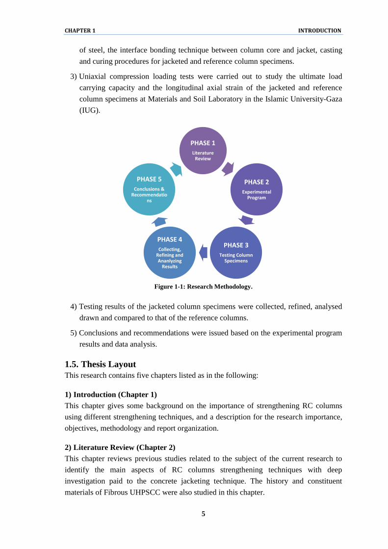
materials were studied for the Fibrous UHPSCC, see Figure 1-1.
2) Experimental program was set up to investigate the properties and mixing
proportions of Normal Strength Concrete (NSC) and Fibrous UHPSCC, properties
CHAPTER 1 INTRODUCTION
5
of steel, the interface bonding technique between column core and jacket, casting
and curing procedures for jacketed and reference column specimens.
3) Uniaxial compression loading tests were carried out to study the ultimate load
carrying capacity and the longitudinal axial strain of the jacketed and reference
column specimens at Materials and Soil Laboratory in the Islamic University-Gaza
(IUG).
Figure 1-1: Research Methodology.
4) Testing results of the jacketed column specimens were collected, refined, analysed
drawn and compared to that of the reference columns.
5) Conclusions and recommendations were issued based on the experimental program
results and data analysis.
1.5. Thesis Layout
This research contains five chapters listed as in the following:
1) Introduction (Chapter 1)
This chapter gives some background on the importance of strengthening RC columns
using different strengthening techniques, and a description for the research importance,
objectives, methodology and report organization.
2) Literature Review (Chapter 2)
This chapter reviews previous studies related to the subject of the current research to
identify the main aspects of RC columns strengthening techniques with deep
investigation paid to the concrete jacketing technique. The history and constituent
materials of Fibrous UHPSCC were also studied in this chapter.
PHASE 1
Literature Review
PHASE 2
Experimental Program
PHASE 3
Testing Column Specimens
PHASE 4
Collecting, Refining and Ananlyzing
Results
PHASE 5
Conclusions & Recommendatio
ns
CHAPTER 1 INTRODUCTION
6
3) Experimental Program (Chapter 3)
This chapter investigates the properties and mixing proportions of NSC and Fibrous
UHPSCC. Also, studies the properties of steel, the interface bonding technique between
column core and jacket, casting and curing procedures, and the application of uniaxial
compression load on the jacketed and reference columns.
4) Results & Discussion (Chapter 4)
This chapter analyzes, discusses and compares the obtained testing results of the
jacketed and reference columns in terms of ultimate load carrying capacity, longitudinal
axial strain and failure patterns.
5) Conclusions and Recommendations (Chapter 5)
This chapter includes the concluded remarks, main recommendations drawn from the
research work.

CHAPTER 2LITERATURE REVIEW
CHAPTER 2 LITERATURE REVIEW
8
2.1. Introduction
This chapter reviews the literature of the available previous studies related to several
strengthening techniques of RC columns, with particular attention devoted to
strengthening square RC columns by concrete jacketing. The properties, history and
application of the Fibrous UHPSCC as a jacketing material were also studied in this
chapter. Restoration, repairing and strengthening are defined below to accurately
distinguish between them:
1) Restoration is improving the damaged buildings so that they can be used again.
2) Repairing is retrieving back the structural performance of damaged buildings to
their original status.
3) Strengthening is improving the structural performance of damaged buildings
beyond their original levels.
Strengthening of existing structures has become a major part of the construction
activity in many countries. This can be attributed to the problems of concrete
structures aging, steel corrosion, variations in temperature, freezing-thawing cycles and
exposure to elevated heat.[1, 7 and 8]
2.2. Strengthening Techniques of RC Columns
The susceptibility of the existing buildings to structural damages largely depends on the
quality of design, detailing and construction. The engineer in many cases can extend
the life span of a building by utilizing a simple repair or strengthening technique. The
choice of repairing or strengthening technique becomes therefore the decisive factor as
the high cost would prevent many building owners from executing essential repair
works.[7, 8, 24 and 28]
Many previous studies have investigated the efficiency of several jacketing techniques
of RC columns as will be discussed in the following sections.
Jacketing RC Columns using Steel Profile 2.2.1.
Steel profile or hoops are used in different shapes to confine and enhance both ductility
and ultimate load carrying capacity of RC columns. Several previous studies focused on
the advantages and disadvantages of this technique.
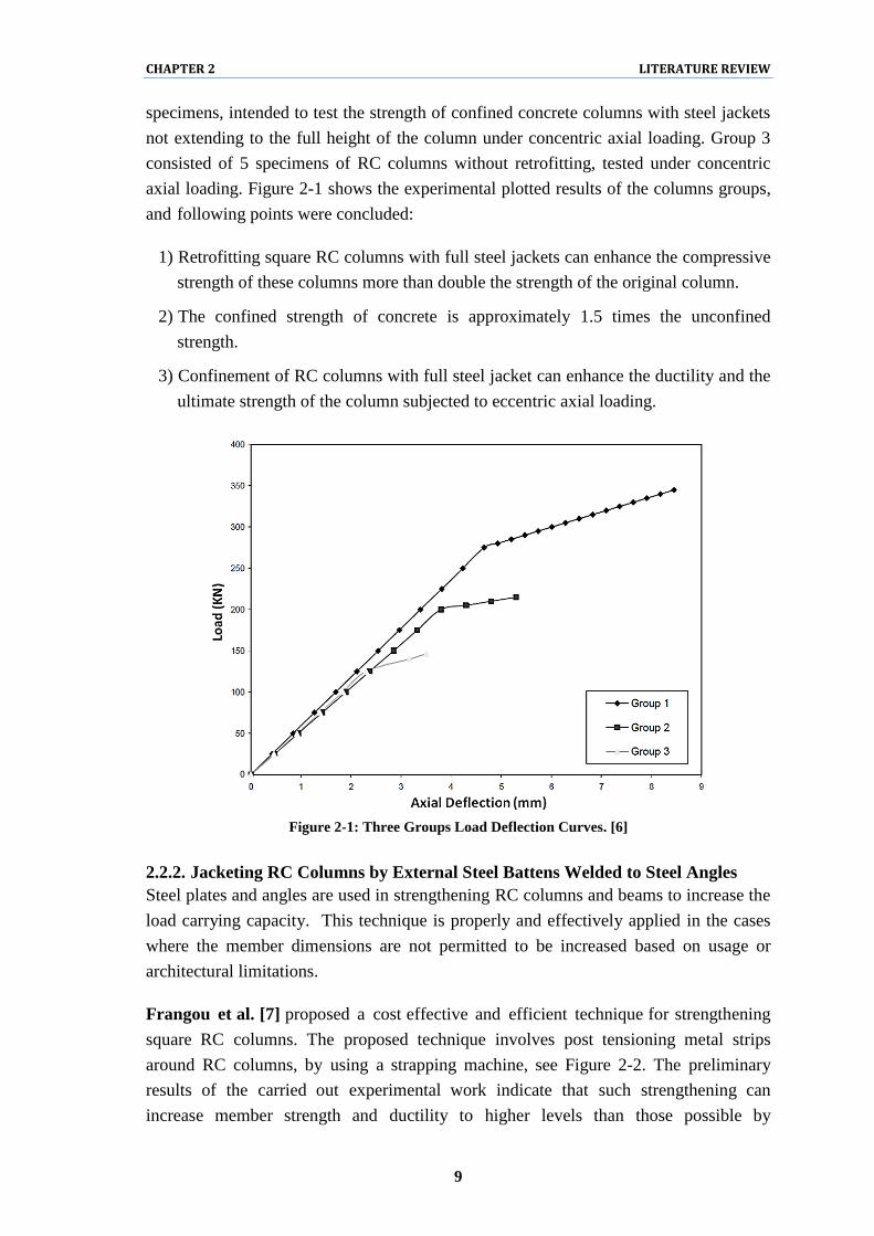
Bsisu [6] proposed that strengthening square RC columns to resist increased loads by
retrofitting with steel jackets is common engineering practice for strengthening and
repair of columns, as it is inexpensive, does not require highly trained labor,
unobtrusive, does not reduce space, easy to inspect and can be applied whilst the
structure is still in use. The study included three square columns groups; Group 1
consisted of 5 column specimens, intended to test the strength of RC columns retrofitted
with full steel jackets under concentric axial loading. Group 2 consisted of 5 column
CHAPTER 2 LITERATURE REVIEW
9
specimens, intended to test the strength of confined concrete columns with steel jackets
not extending to the full height of the column under concentric axial loading. Group 3
consisted of 5 specimens of RC columns without retrofitting, tested under concentric
axial loading. Figure 2-1 shows the experimental plotted results of the columns groups,
and following points were concluded:
1) Retrofitting square RC columns with full steel jackets can enhance the compressive
strength of these columns more than double the strength of the original column.
2) The confined strength of concrete is approximately 1.5 times the unconfined
strength.
3) Confinement of RC columns with full steel jacket can enhance the ductility and the
ultimate strength of the column subjected to eccentric axial loading.
Figure 2-1: Three Groups Load Deflection Curves. [6]
Jacketing RC Columns by External Steel Battens Welded to Steel Angles 2.2.2.
Steel plates and angles are used in strengthening RC columns and beams to increase the
load carrying capacity. This technique is properly and effectively applied in the cases
where the member dimensions are not permitted to be increased based on usage or
architectural limitations.
Frangou et al. [7] proposed a cost effective and efficient technique for strengthening
square RC columns. The proposed technique involves post tensioning metal strips
around RC columns, by using a strapping machine, see Figure 2-2. The preliminary
results of the carried out experimental work indicate that such strengthening can
increase member strength and ductility to higher levels than those possible by

CHAPTER 2 LITERATURE REVIEW
10
conventional reinforcement, at a fraction of the time and cost required by alternative
techniques. The study concluded the followings findings:
1) The strapping technique has been demonstrated to effectively strengthen specimens
tested axially and in bending. The low cost of the materials used, and the ease and
speed of application make this technique very competitive for the repair and
strengthening of RC columns.
2) A very important factor contributing to the success of the strapping technique is the
fact that a tensioning force is applied. The lack of such a force could lead to a
devastating reduction in the effectiveness of confinement.
Figure 2-2: Detailing of Plates and Angles. [7]
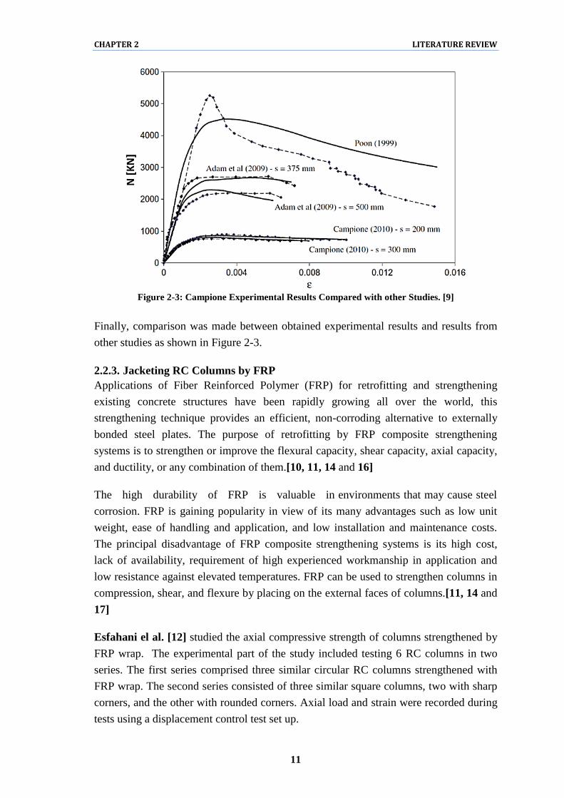
Campione [9] studied the response on square RC columns externally strengthened with
steel angles and battens subjected to axial force and bending moment. The original
contribution of the study was the investigation of the effect of steel angles and strips
externally welded to the RC columns both in term of moment axial forces increments
and available ductility. Finally parametric analyses in term of available ductility and
moment curvature diagrams were carried out to highlight the effectiveness of this
reinforcing technique. The following remarks were drawn:
1) If the pitch of strips is low and respects limits given by most of the existing codes
(lower than 0.5 column width) buckling effects do not penalize the load carrying
capacity of steel angels and high confinement effects on concrete core are reached.
2) The increment in the load carrying capacity of the strengthened members is
significant both in term of axial force and bending moment due to the coupled
effects of confinement on concrete core and due to the composite action.
3) Significant increases in ductility are achieved by using steel angles and strips also
with very high levels of axial forces, reaching up to 10.
CHAPTER 2 LITERATURE REVIEW
11
Figure 2-3: Campione Experimental Results Compared with other Studies. [9]
Finally, comparison was made between obtained experimental results and results from
other studies as shown in Figure 2-3.
Jacketing RC Columns by FRP 2.2.3.
Applications of Fiber Reinforced Polymer (FRP) for retrofitting and strengthening
existing concrete structures have been rapidly growing all over the world, this
strengthening technique provides an efficient, non-corroding alternative to externally
bonded steel plates. The purpose of retrofitting by FRP composite strengthening
systems is to strengthen or improve the flexural capacity, shear capacity, axial capacity,
and ductility, or any combination of them.[10, 11, 14 and 16]
The high durability of FRP is valuable in environments that may cause steel
corrosion. FRP is gaining popularity in view of its many advantages such as low unit
weight, ease of handling and application, and low installation and maintenance costs.
The principal disadvantage of FRP composite strengthening systems is its high cost,
lack of availability, requirement of high experienced workmanship in application and
low resistance against elevated temperatures. FRP can be used to strengthen columns in
compression, shear, and flexure by placing on the external faces of columns.[11, 14 and
17]
Esfahani el al. [12] studied the axial compressive strength of columns strengthened by
FRP wrap. The experimental part of the study included testing 6 RC columns in two
series. The first series comprised three similar circular RC columns strengthened with
FRP wrap. The second series consisted of three similar square columns, two with sharp
corners, and the other with rounded corners. Axial load and strain were recorded during
tests using a displacement control test set up.
CHAPTER 2 LITERATURE REVIEW
12
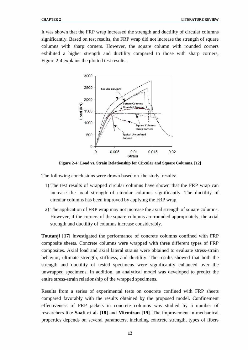
It was shown that the FRP wrap increased the strength and ductility of circular columns
significantly. Based on test results, the FRP wrap did not increase the strength of square
columns with sharp corners. However, the square column with rounded corners
exhibited a higher strength and ductility compared to those with sharp corners,
Figure 2-4 explains the plotted test results.
Figure 2-4: Load vs. Strain Relationship for Circular and Square Columns. [12]
The following conclusions were drawn based on the study results:
1) The test results of wrapped circular columns have shown that the FRP wrap can
increase the axial strength of circular columns significantly. The ductility of
circular columns has been improved by applying the FRP wrap.
2) The application of FRP wrap may not increase the axial strength of square columns.
However, if the corners of the square columns are rounded appropriately, the axial
strength and ductility of columns increase considerably.
Toutanji [17] investigated the performance of concrete columns confined with FRP
composite sheets. Concrete columns were wrapped with three different types of FRP
composites. Axial load and axial lateral strains were obtained to evaluate stress-strain
behavior, ultimate strength, stiffness, and ductility. The results showed that both the
strength and ductility of tested specimens were significantly enhanced over the
unwrapped specimens. In addition, an analytical model was developed to predict the
entire stress-strain relationship of the wrapped specimens.
Results from a series of experimental tests on concrete confined with FRP sheets
compared favorably with the results obtained by the proposed model. Confinement
effectiveness of FRP jackets in concrete columns was studied by a number of
researchers like Saafi et al. [18] and Mirmiran [19]. The improvement in mechanical
properties depends on several parameters, including concrete strength, types of fibers

CHAPTER 2 LITERATURE REVIEW
13
and resin, fiber volume fraction and fiber orientation in the jacket, jacket thickness,
shape of cross section, column length diameter ratio, and the interface bonding between
core and jacket.
Spoelstra and Monti [20] developed a uniaxial model for concrete confined with FRP.
The model explicitly accounted for the continuous interaction with the FRP wrap due to
the lateral strain of concrete through an incremental iterative approach. The relation
between the axial and lateral strains was implicitly derived through equilibrium between
the dilating confined concrete and the wrap. The model was compared with a set of
experimental tests, and showed very good agreement in both the axial stress- strain and
the stress-lateral strain response.
Seible et al. [21] conducted a large scale test on one as built and four composite
wrapped rectangular flexural bridge spandrel columns to assess the effectiveness of
different retrofit schemes using FRP composite jackets. The tests showed that FRP
composite jacketing systems clearly can be installed without affecting the overall
geometry or appearance of the structure. They emphasized the importance of designing
retrofit strategies to control the mode of failure. Retrofitting one weakness without
considering other potential modes of failure could lead to ineffective and poor designs.
Strengthening RC Columns by Concrete Jacketing 2.2.4.
There are many factors affecting the behavior of strengthened RC columns by concrete
jacketing, these factors can be summarized as follows:
1) Concrete compressive strength of the original column.
2) Concrete jacket thickness.
3) Stress level of the original column.
4) Amount and distribution of the transverse reinforcement of jacket.
5) Contact surface between the original column and the jacket.
6) Use of shear keys and shear connectors and their configuration.
7) Jacket height and loading area.
8) Rectangularity ratio of the original column.
9) End conditions of the original column.
10) Eccentricity of the applied loads.
11) Casting direction of concrete.
12) Position of the original column.
13) Concrete compressive strength of the RC jacket.
14) Vertical reinforcement of the RC jacket.

CHAPTER 2 LITERATURE REVIEW
14
Experimental investigations of strengthened or repaired columns are generally
conducted on unloaded original columns, in spite of the fact that it is very difficult to
have an unloaded strengthened column in the field. Studying the behavior of
strengthened column with preloading the original column is very important but also is
very difficult experimentally.[22 and 25]
Allam [22] carried out an experimental study to investigate the behavior of the original
columns and the effect of the jacket height while the original columns were under
loading. Six parameters affecting the behavior of strengthened RC columns were
studied; jacket thickness, stress level in the original column, concrete strength of the
original column, stirrups of jacket, shear connectors, and jacket height respectively. The
tested specimens were divided into six groups; each group was concerned with one of
the mentioned six parameters. The following points were concluded:
1) As the preloading stress in the original column increases the ultimate load of the
jacketed column decreases by 19%, 31%, and 42% for the cases of preloading by
the working load, 0.5 of the failure load, and 0.8 of the failure load respectively.
2) Vertical strains in the jacket decreases as the stress level increases in the original
column which means that jacket efficiency decreases as the stress level increases.
3) The lateral tensile strains at the top of the jacket increases as the stress level in the
original column increases after the first crack load.
4) In the case of the preloaded columns, the vertical strain at the top of the jacket is
less than that for the case of total release of load. In the case of the preloaded
columns, the vertical strain in the original columns is more than that in the case of
total release of load at the ultimate load. The Calculation of the strength of the
jacket as a RC column overestimates the strength. The overestimation increases in
case of preloaded columns over the cases of total release of load.
5) In the case of loading the original column and the jacket for the preloaded
columns, the ultimate load increased by 1.81 times the ultimate load for loading the
original column only.
6) In the case of total release of load, the ultimate load increased by 2.05 times the
ultimate load for loading the original column only.
Meda et al. [23] Studied the possibility of strengthening existing RC columns with a
technique based on the application of a high performance fiber reinforced concrete
(HPFRC) jacket having 170MPa compressive strength. The geometry of unjacketed,
HPFRC jacketed, and traditional jacketed RC columns are ordered in Figure 2-5 from
left to right respectively.
CHAPTER 2 LITERATURE REVIEW
15
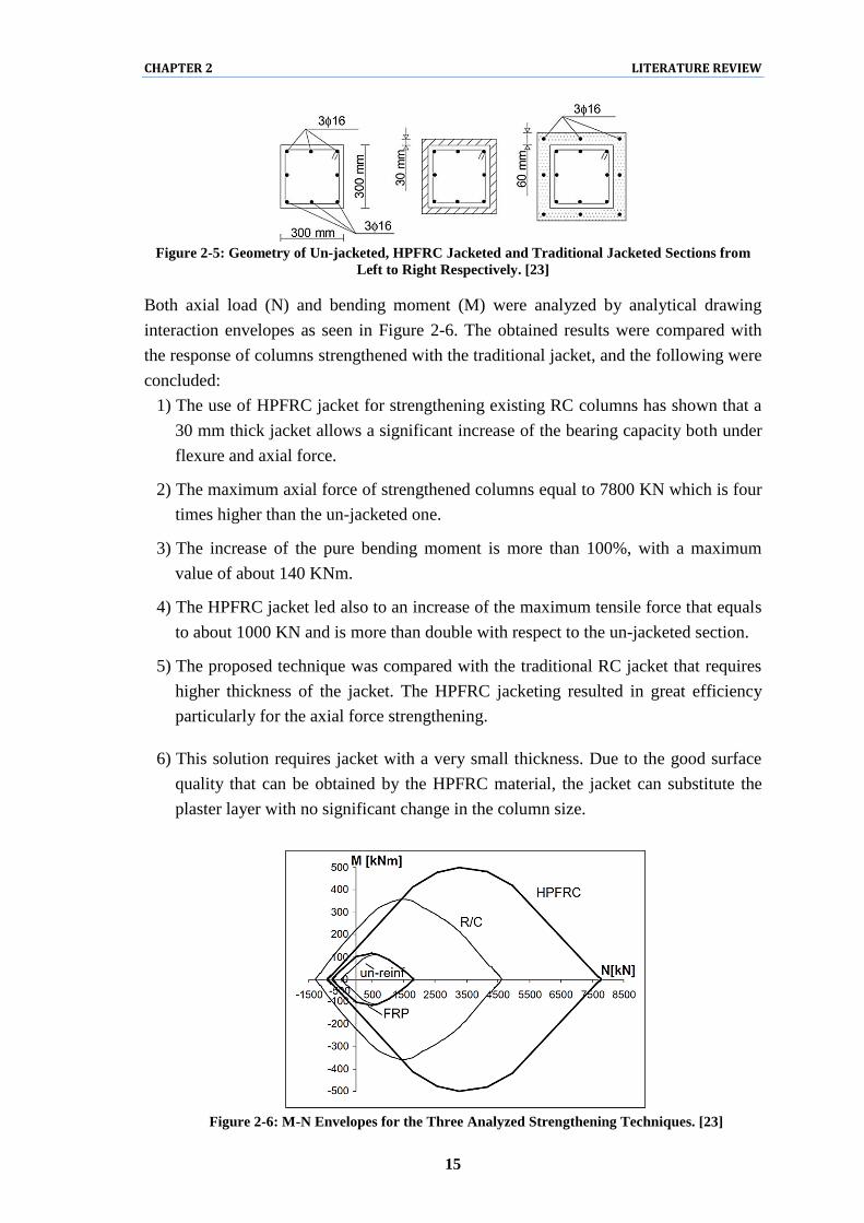
Figure 2-5: Geometry of Un-jacketed, HPFRC Jacketed and Traditional Jacketed Sections from
Left to Right Respectively. [23]
Both axial load (N) and bending moment (M) were analyzed by analytical drawing
interaction envelopes as seen in Figure 2-6. The obtained results were compared with
the response of columns strengthened with the traditional jacket, and the following were
concluded:
1) The use of HPFRC jacket for strengthening existing RC columns has shown that a
30 mm thick jacket allows a significant increase of the bearing capacity both under
flexure and axial force.
2) The maximum axial force of strengthened columns equal to 7800 KN which is four
times higher than the un-jacketed one.
3) The increase of the pure bending moment is more than 100%, with a maximum
value of about 140 KNm.
4) The HPFRC jacket led also to an increase of the maximum tensile force that equals
to about 1000 KN and is more than double with respect to the un-jacketed section.
5) The proposed technique was compared with the traditional RC jacket that requires
higher thickness of the jacket. The HPFRC jacketing resulted in great efficiency
particularly for the axial force strengthening.
6) This solution requires jacket with a very small thickness. Due to the good surface
quality that can be obtained by the HPFRC material, the jacket can substitute the
plaster layer with no significant change in the column size.
Figure 2-6: M-N Envelopes for the Three Analyzed Strengthening Techniques. [23]
CHAPTER 2 LITERATURE REVIEW
16
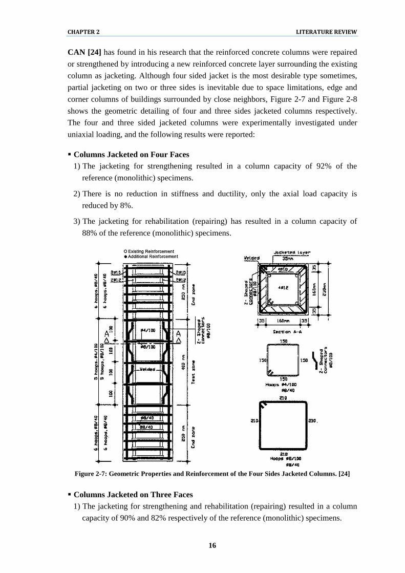
CAN [24] has found in his research that the reinforced concrete columns were repaired
or strengthened by introducing a new reinforced concrete layer surrounding the existing
column as jacketing. Although four sided jacket is the most desirable type sometimes,
partial jacketing on two or three sides is inevitable due to space limitations, edge and
corner columns of buildings surrounded by close neighbors, Figure 2-7 and Figure 2-8
shows the geometric detailing of four and three sides jacketed columns respectively.
The four and three sided jacketed columns were experimentally investigated under
uniaxial loading, and the following results were reported:
Columns Jacketed on Four Faces
1) The jacketing for strengthening resulted in a column capacity of 92% of the
reference (monolithic) specimens.
2) There is no reduction in stiffness and ductility, only the axial load capacity is
reduced by 8%.
3) The jacketing for rehabilitation (repairing) has resulted in a column capacity of
88% of the reference (monolithic) specimens.
Figure 2-7: Geometric Properties and Reinforcement of the Four Sides Jacketed Columns. [24]
Columns Jacketed on Three Faces
1) The jacketing for strengthening and rehabilitation (repairing) resulted in a column
capacity of 90% and 82% respectively of the reference (monolithic) specimens.

CHAPTER 2 LITERATURE REVIEW
17
2) Column stiffness has increased by 40% in repaired specimens and 51% in reha-
bilitation (monolithic) specimens.
3) The strengthened column has dissipated 14% less energy and the repaired column
23% less energy as compared to the monolithic column.
Jacketing on all four faces is more efficient from strength and ductility points of view as
compared to jacketing on three faces only.
Figure 2-8: Geometric Properties and Reinforcement of the Three Sides Jacketed Columns. [24]
Mourad et al. [25] has investigated a series of 10 small scale square RC columns,
preloaded under axial compression up to various fractions (0%, 60%, 80%, and 100%)
of its ultimate load and repaired using high strength ferrocement jackets containing two
layers of steel reinforcement in high strength mortar then retested to failure. The overall
response of the specimens was investigated in terms of load carrying capacity, axial and
lateral displacement. Figure 2-9 superimpose the axial and lateral displacement with
load carrying capacity for control columns (SC-2), jacketed columns (SJ-0-2),
strengthened preloaded columns (SJ-60-1 and SJ-80-1) and strengthened failed column
(SJ-100-1).The study concluded the following points:
1) The test results indicated that jacketing reinforced concrete square columns with
high strength ferrocement provided about 33% and 26% increases in axial load
capacity and axial stiffness respectively, compared to the control columns.

CHAPTER 2 LITERATURE REVIEW
18
2) The test results also indicated that repairing similar reinforced concrete columns
(after preloading them to failure) with the same ferrocement jacket almost restored
their original load capacity and stiffness. Furthermore, the repaired columns failed
in a ductile manner compared to the brittle failure exhibited by the control columns.
Figure 2-9: Load-Displacement Relationships for Tested Specimens. [25]
Abdelrahman [26] studied the jackets surrounding the full perimeter of the original
columns which are normally used for repair of the interior columns. The level of stress
in the column before repair is assumed to be relatively low to extent that the preloading
of the original column does not affect the overall behavior significantly. He also studied
the load application on only sectional area of the original column. It was found that the
load transfer from the original column to the jacket over a distance about 2 to 3 times
the breadth of the original column. The ultimate load of this strengthened column was
less than the increase in the cross sectional area.
Ersoy et al. [27] carried out a research in repair and strengthening of columns by
jacketing. The columns were tested under uniaxial load, four basic columns having
identical dimensions and reinforcement were tested under monotonic axial loading.
After the test, the basic columns were jacketed and retested. The intervention was
called either a repair or strengthening jacket depending on whether or not the
basic specimens had been loaded to a damaged level.
Two of the specimens were jacketed after unloading the basic column, while the other
two were jacketed under loading (the load is still in practice), and both cases were
investigated. The original concrete columns have cross section of 13×13cm, 65cm in
length, 4Ø10 main steel reinforcement, and 25Ø4/m stirrups. While the jacketed
columns have cross section of 18×18cm, 65cm in length, 4Ø10 jacket reinforcement,
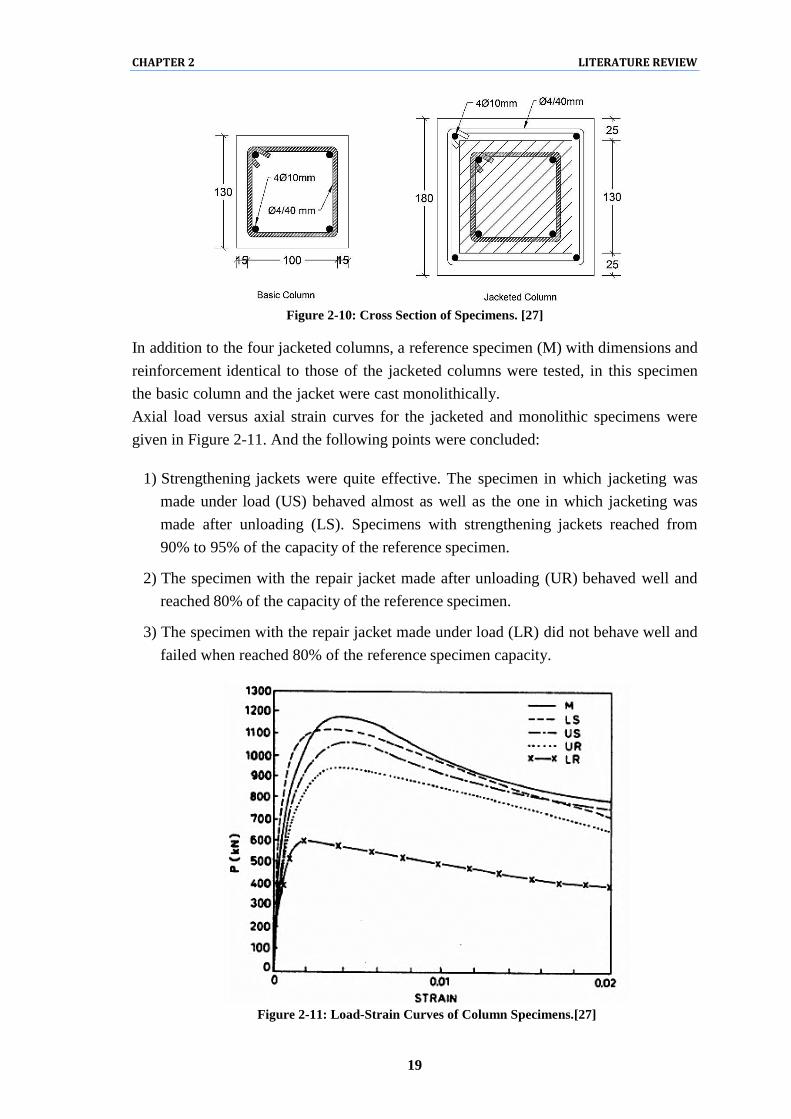
and 25Ø4/m jacket stirrups. Figure 2-10 shows the cross section of the specimens.
CHAPTER 2 LITERATURE REVIEW
19
Figure 2-10: Cross Section of Specimens. [27]
In addition to the four jacketed columns, a reference specimen (M) with dimensions and
reinforcement identical to those of the jacketed columns were tested, in this specimen
the basic column and the jacket were cast monolithically.
Axial load versus axial strain curves for the jacketed and monolithic specimens were
given in Figure 2-11. And the following points were concluded:
1) Strengthening jackets were quite effective. The specimen in which jacketing was
made under load (US) behaved almost as well as the one in which jacketing was
made after unloading (LS). Specimens with strengthening jackets reached from
90% to 95% of the capacity of the reference specimen.
2) The specimen with the repair jacket made after unloading (UR) behaved well and
reached 80% of the capacity of the reference specimen.
3) The specimen with the repair jacket made under load (LR) did not behave well and
failed when reached 80% of the reference specimen capacity.
Figure 2-11: Load-Strain Curves of Column Specimens.[27]
CHAPTER 2 LITERATURE REVIEW
20
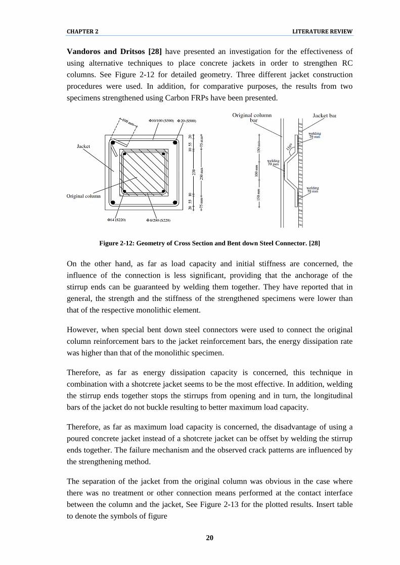
Vandoros and Dritsos [28] have presented an investigation for the effectiveness of
using alternative techniques to place concrete jackets in order to strengthen RC
columns. See Figure 2-12 for detailed geometry. Three different jacket construction
procedures were used. In addition, for comparative purposes, the results from two
specimens strengthened using Carbon FRPs have been presented.
Figure 2-12: Geometry of Cross Section and Bent down Steel Connector. [28]
On the other hand, as far as load capacity and initial stiffness are concerned, the
influence of the connection is less significant, providing that the anchorage of the
stirrup ends can be guaranteed by welding them together. They have reported that in
general, the strength and the stiffness of the strengthened specimens were lower than
that of the respective monolithic element.
However, when special bent down steel connectors were used to connect the original
column reinforcement bars to the jacket reinforcement bars, the energy dissipation rate
was higher than that of the monolithic specimen.
Therefore, as far as energy dissipation capacity is concerned, this technique in
combination with a shotcrete jacket seems to be the most effective. In addition, welding
the stirrup ends together stops the stirrups from opening and in turn, the longitudinal
bars of the jacket do not buckle resulting to better maximum load capacity.
Therefore, as far as maximum load capacity is concerned, the disadvantage of using a
poured concrete jacket instead of a shotcrete jacket can be offset by welding the stirrup
ends together. The failure mechanism and the observed crack patterns are influenced by
the strengthening method.
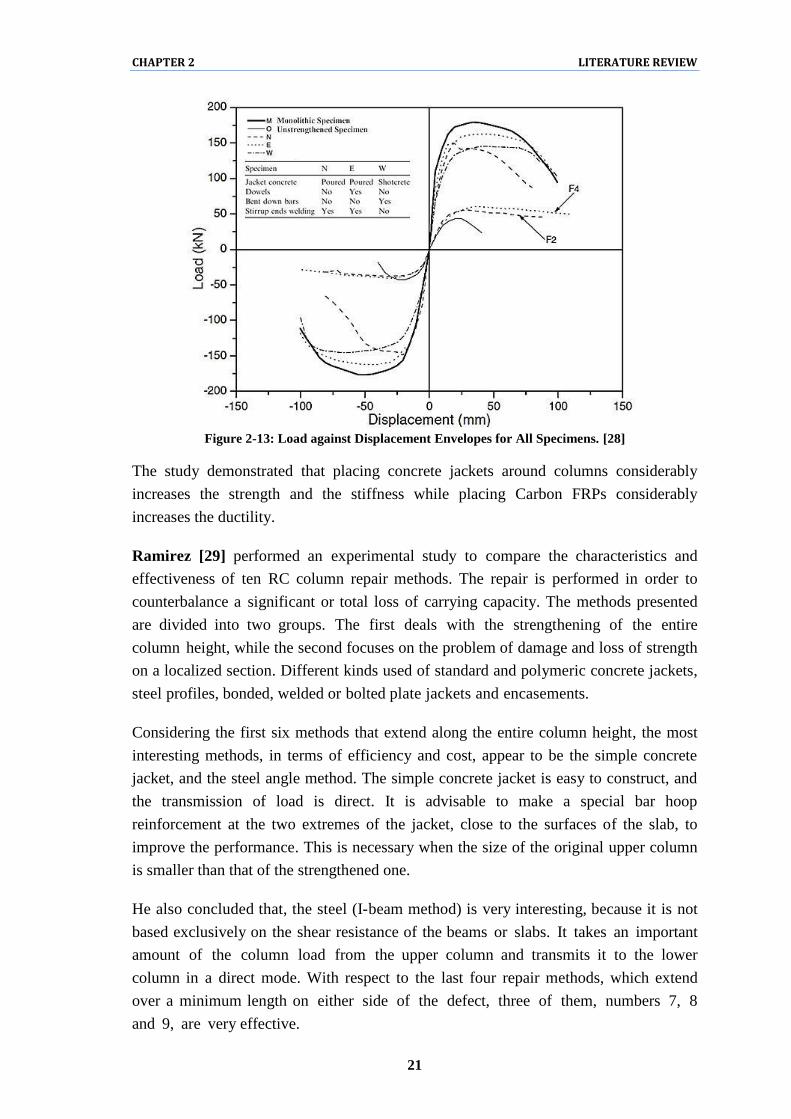
The separation of the jacket from the original column was obvious in the case where
there was no treatment or other connection means performed at the contact interface
between the column and the jacket, See Figure 2-13 for the plotted results. Insert table
to denote the symbols of figure
CHAPTER 2 LITERATURE REVIEW
21
Figure 2-13: Load against Displacement Envelopes for All Specimens. [28]
The study demonstrated that placing concrete jackets around columns considerably
increases the strength and the stiffness while placing Carbon FRPs considerably
increases the ductility.
Ramirez [29] performed an experimental study to compare the characteristics and
effectiveness of ten RC column repair methods. The repair is performed in order to
counterbalance a significant or total loss of carrying capacity. The methods presented
are divided into two groups. The first deals with the strengthening of the entire
column height, while the second focuses on the problem of damage and loss of strength
on a localized section. Different kinds used of standard and polymeric concrete jackets,
steel profiles, bonded, welded or bolted plate jackets and encasements.
Considering the first six methods that extend along the entire column height, the most
interesting methods, in terms of efficiency and cost, appear to be the simple concrete
jacket, and the steel angle method. The simple concrete jacket is easy to construct, and
the transmission of load is direct. It is advisable to make a special bar hoop
reinforcement at the two extremes of the jacket, close to the surfaces of the slab, to
improve the performance. This is necessary when the size of the original upper column
is smaller than that of the strengthened one.
He also concluded that, the steel (I-beam method) is very interesting, because it is not
based exclusively on the shear resistance of the beams or slabs. It takes an important
amount of the column load from the upper column and transmits it to the lower
column in a direct mode. With respect to the last four repair methods, which extend
over a minimum length on either side of the defect, three of them, numbers 7, 8
and 9, are very effective.
CHAPTER 2 LITERATURE REVIEW
22
Methods based on a polymeric resin concrete jacket or steel plate jacket with injection
of voids with resin mortar, numbers 7 and 9 respectively, present high efficiency at a
low or moderate cost. The ratio between the failure load following repair and the
theoretical prediction has been greater than 1, obtaining values of the same order of
magnitude as for undamaged virgin columns. The repairs are thin and short. The main
problems with them may be low resistance against fire. Procedure no. 8 consisting of
angle bars with pre stressed bolts, has a very good behavior and seems to be very
reliable, although it is expensive and troublesome to apply. It may be of interest for
emergency strengthening.
2.3. Fibrous Ultra High Performance Self-Compacting Concrete
The jacketing material applied in this research was the Forta-Ferro Polypropylene
Fibrous Ultra High Performance Self-Compacting Concrete (Fibrous UHPSCC), as
discussed later in this chapter. The following points are explaining the main related
concepts, components and keys of this material.
Ultra-High Performance Concrete (UHPC) 2.3.1.
The Ultra High Performance Concrete (UHPC) with a compressive strength more than
100 MPa and improved durability marks developing step in concrete industry. This high
performance material offers a variety of interesting applications. It allows the
construction of sustainable and economic buildings with an extraordinary slim design.
Its high strength and ductility makes it the ultimate building material e.g. for bridge
decks, storage halls, thin-wall shell structures and highly loaded columns. Beside its
improved strength properties, its outstanding resistance against all kinds of corrosion is
an additional milestone on the way towards no maintenance constructions.[30, 34 and
37]
UHPC has very special properties that are remarkably different to the properties of
normal and high performance concrete. UHPC is formulated by combining Portland
cement, silica fume, quartz powder, high range water reducer, water, and steel or
organic fibers. For complete utilization of UHPC’s superior properties, special
knowledge is required for production, construction and design.[30, 34 and 35]
Self-Compacting Concrete (SCC) 2.3.2.
A structural concrete which strongly deviates from NSC in the fresh state as it flows
without the application of additional compaction energy. SCC can be defined as a
concrete that is able to flow in the interior of the formwork, filling it in a natural manner
and passing through the reinforcing bars and other obstacles, flowing and consolidating
under the action of its own weight leaving no segregation or honeycombing
problems.[31 and 32]
CHAPTER 2 LITERATURE REVIEW
23
The Developing History of UHPSCC 2.3.3.
The development of the high strength concrete HSC, SCC and UHPSCC are all
summarized in Table 2-1.
Table 2-1: UHPSCC Development.[32]
Year UHPC History Year SCC History
1950
Concrete with a compressive
strength of 34MPa was considered
as high strength concrete
1988 The first time SCC was
developed in Japan
1960 High strength concrete were
developed in labs of only 80MPa 1993
The prototype of self-compacting
concrete was first completed using
materials already on the market
1980
High performance concrete of
100MPa were developed in
Denmark for special applications in
the security industry and protective
defense constructions
1997 The SCC was used for the first
time in Europe in the civil works
1985 First research was conducted on
the applications of UHPC 2002
European specification and
guidelines were developed for SCC
More
recently
Compressive strengths
approaching 120MPa is used
More
recently
SCC is used commercially in
Japan, Europe, USA, … etc.
Some researches take place on matching the UHPC and SCC in one mix in order to develop the
UHPSCC, which is used recently in many special engineering structures.
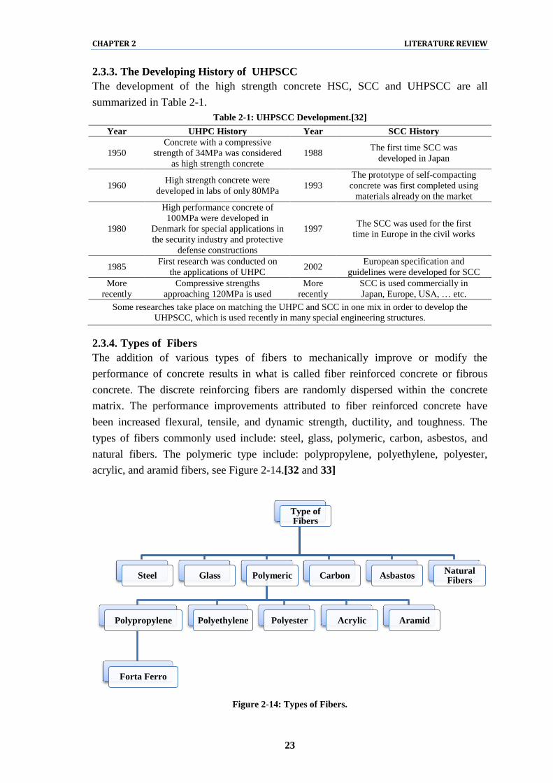
Types of Fibers 2.3.4.
The addition of various types of fibers to mechanically improve or modify the
performance of concrete results in what is called fiber reinforced concrete or fibrous
concrete. The discrete reinforcing fibers are randomly dispersed within the concrete
matrix. The performance improvements attributed to fiber reinforced concrete have
been increased flexural, tensile, and dynamic strength, ductility, and toughness. The
types of fibers commonly used include: steel, glass, polymeric, carbon, asbestos, and
natural fibers. The polymeric type include: polypropylene, polyethylene, polyester,
acrylic, and aramid fibers, see Figure 2-14.[32 and 33]
Figure 2-14: Types of Fibers.
Type of Fibers
Steel Glass Polymeric
Polypropylene
Forta Ferro
Polyethylene Polyester Acrylic Aramid
Carbon Asbastos Natural Fibers
CHAPTER 2 LITERATURE REVIEW
24
The use of fibers as reinforcement in concrete precedes the use of conventionally
reinforced concrete. Polypropylene fibers are used to provide what is termed secondary
reinforcement, or the encouragement of a desired material behavior such as decreased
plastic and shrinkage cracking and improved toughness. Several manufacturers have
been selling the fibers to improve the concrete's resistance to the formation of plastic
shrinkage cracking and as secondary reinforcement as a replacement for welded wire
fabric.[33, 34 and 35]
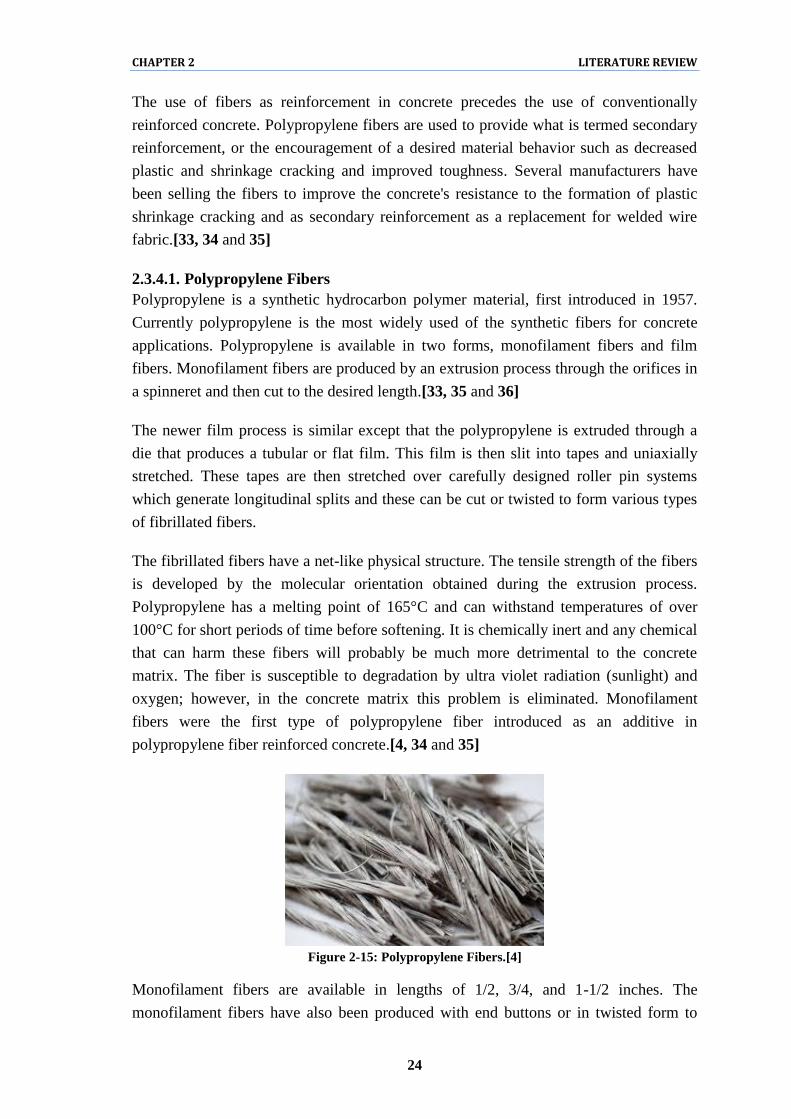
Polypropylene Fibers 2.3.4.1.
Polypropylene is a synthetic hydrocarbon polymer material, first introduced in 1957.
Currently polypropylene is the most widely used of the synthetic fibers for concrete
applications. Polypropylene is available in two forms, monofilament fibers and film
fibers. Monofilament fibers are produced by an extrusion process through the orifices in
a spinneret and then cut to the desired length.[33, 35 and 36]
The newer film process is similar except that the polypropylene is extruded through a
die that produces a tubular or flat film. This film is then slit into tapes and uniaxially
stretched. These tapes are then stretched over carefully designed roller pin systems
which generate longitudinal splits and these can be cut or twisted to form various types
of fibrillated fibers.
The fibrillated fibers have a net-like physical structure. The tensile strength of the fibers
is developed by the molecular orientation obtained during the extrusion process.
Polypropylene has a melting point of 165°C and can withstand temperatures of over
100°C for short periods of time before softening. It is chemically inert and any chemical
that can harm these fibers will probably be much more detrimental to the concrete
matrix. The fiber is susceptible to degradation by ultra violet radiation (sunlight) and
oxygen; however, in the concrete matrix this problem is eliminated. Monofilament
fibers were the first type of polypropylene fiber introduced as an additive in
polypropylene fiber reinforced concrete.[4, 34 and 35]
Figure 2-15: Polypropylene Fibers.[4]
Monofilament fibers are available in lengths of 1/2, 3/4, and 1-1/2 inches. The
monofilament fibers have also been produced with end buttons or in twisted form to
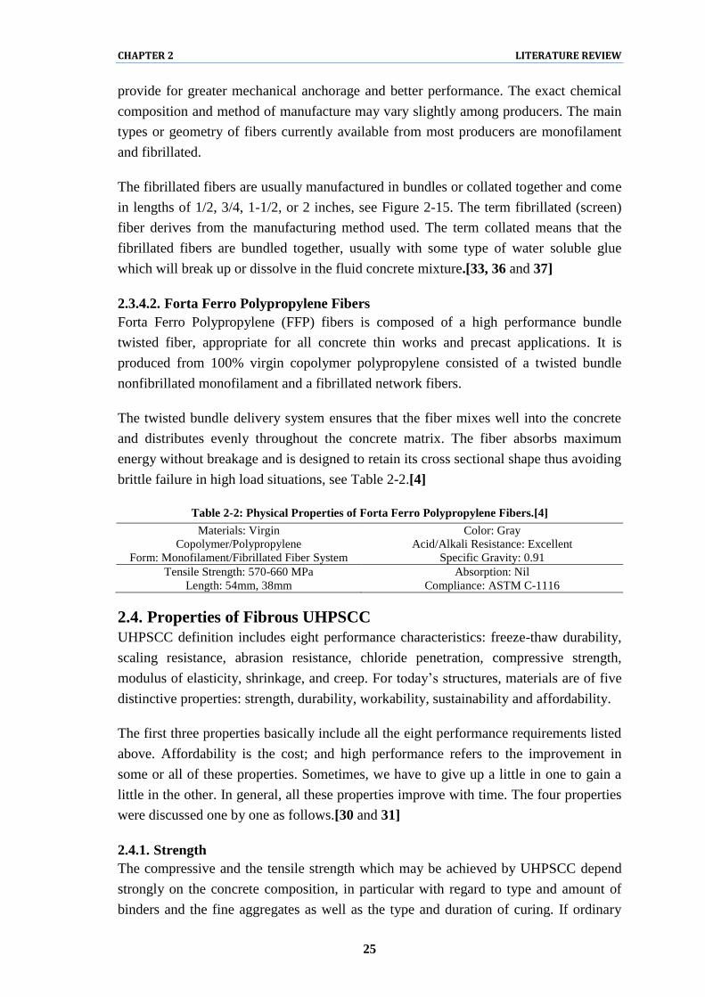
CHAPTER 2 LITERATURE REVIEW
25
provide for greater mechanical anchorage and better performance. The exact chemical
composition and method of manufacture may vary slightly among producers. The main
types or geometry of fibers currently available from most producers are monofilament
and fibrillated.
The fibrillated fibers are usually manufactured in bundles or collated together and come
in lengths of 1/2, 3/4, 1-1/2, or 2 inches, see Figure 2-15. The term fibrillated (screen)
fiber derives from the manufacturing method used. The term collated means that the
fibrillated fibers are bundled together, usually with some type of water soluble glue
which will break up or dissolve in the fluid concrete mixture.[33, 36 and 37]
Forta Ferro Polypropylene Fibers 2.3.4.2.
Forta Ferro Polypropylene (FFP) fibers is composed of a high performance bundle
twisted fiber, appropriate for all concrete thin works and precast applications. It is
produced from 100% virgin copolymer polypropylene consisted of a twisted bundle
nonfibrillated monofilament and a fibrillated network fibers.
The twisted bundle delivery system ensures that the fiber mixes well into the concrete
and distributes evenly throughout the concrete matrix. The fiber absorbs maximum
energy without breakage and is designed to retain its cross sectional shape thus avoiding
brittle failure in high load situations, see Table 2-2.[4]
Table 2-2: Physical Properties of Forta Ferro Polypropylene Fibers.[4]
Materials: Virgin
Copolymer/Polypropylene
Form: Monofilament/Fibrillated Fiber System
Color: Gray
Acid/Alkali Resistance: Excellent
Specific Gravity: 0.91
Tensile Strength: 570-660 MPa
Length: 54mm, 38mm
Absorption: Nil
Compliance: ASTM C-1116
2.4. Properties of Fibrous UHPSCC
UHPSCC definition includes eight performance characteristics: freeze-thaw durability,
scaling resistance, abrasion resistance, chloride penetration, compressive strength,
modulus of elasticity, shrinkage, and creep. For today’s structures, materials are of five
distinctive properties: strength, durability, workability, sustainability and affordability.
The first three properties basically include all the eight performance requirements listed
above. Affordability is the cost; and high performance refers to the improvement in
some or all of these properties. Sometimes, we have to give up a little in one to gain a
little in the other. In general, all these properties improve with time. The four properties
were discussed one by one as follows.[30 and 31]
Strength 2.4.1.
The compressive and the tensile strength which may be achieved by UHPSCC depend
strongly on the concrete composition, in particular with regard to type and amount of
binders and the fine aggregates as well as the type and duration of curing. If ordinary
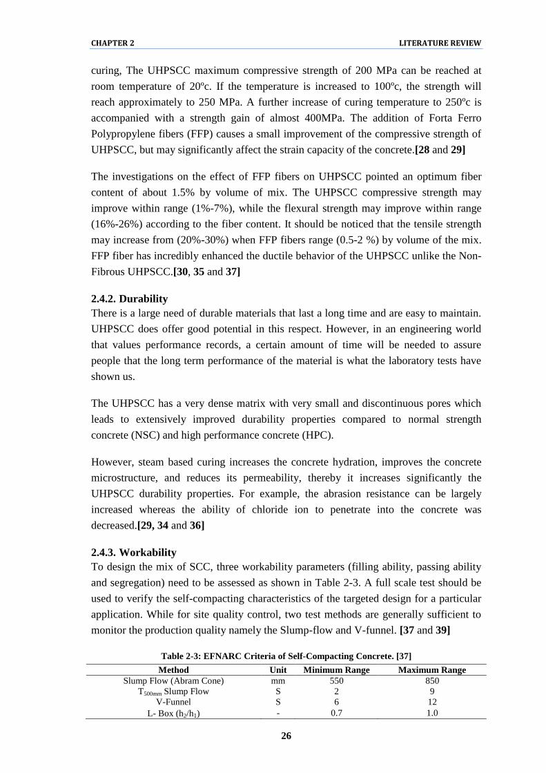
CHAPTER 2 LITERATURE REVIEW
26
curing, The UHPSCC maximum compressive strength of 200 MPa can be reached at
room temperature of 20ºc. If the temperature is increased to 100ºc, the strength will
reach approximately to 250 MPa. A further increase of curing temperature to 250ºc is
accompanied with a strength gain of almost 400MPa. The addition of Forta Ferro
Polypropylene fibers (FFP) causes a small improvement of the compressive strength of
UHPSCC, but may significantly affect the strain capacity of the concrete.[28 and 29]
The investigations on the effect of FFP fibers on UHPSCC pointed an optimum fiber
content of about 1.5% by volume of mix. The UHPSCC compressive strength may
improve within range (1%-7%), while the flexural strength may improve within range
(16%-26%) according to the fiber content. It should be noticed that the tensile strength
may increase from (20%-30%) when FFP fibers range (0.5-2 %) by volume of the mix.
FFP fiber has incredibly enhanced the ductile behavior of the UHPSCC unlike the Non-
Fibrous UHPSCC.[30, 35 and 37]
Durability 2.4.2.
There is a large need of durable materials that last a long time and are easy to maintain.
UHPSCC does offer good potential in this respect. However, in an engineering world
that values performance records, a certain amount of time will be needed to assure
people that the long term performance of the material is what the laboratory tests have
shown us.
The UHPSCC has a very dense matrix with very small and discontinuous pores which
leads to extensively improved durability properties compared to normal strength
concrete (NSC) and high performance concrete (HPC).
However, steam based curing increases the concrete hydration, improves the concrete
microstructure, and reduces its permeability, thereby it increases significantly the
UHPSCC durability properties. For example, the abrasion resistance can be largely
increased whereas the ability of chloride ion to penetrate into the concrete was
decreased.[29, 34 and 36]
Workability 2.4.3.
To design the mix of SCC, three workability parameters (filling ability, passing ability
and segregation) need to be assessed as shown in Table 2-3. A full scale test should be
used to verify the self-compacting characteristics of the targeted design for a particular
application. While for site quality control, two test methods are generally sufficient to
monitor the production quality namely the Slump-flow and V-funnel. [37 and 39]
Table 2-3: EFNARC Criteria of Self-Compacting Concrete. [37]
Method Unit Minimum Range Maximum Range
Slump Flow (Abram Cone) mm 550 850
T500mm Slump Flow S 2 9
V-Funnel S 6 12
L- Box (h2/h1) - 0.7 1.0
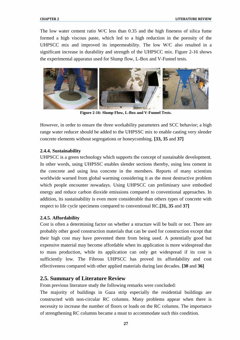
CHAPTER 2 LITERATURE REVIEW
27
The low water cement ratio W/C less than 0.35 and the high fineness of silica fume
formed a high viscous paste, which led to a high reduction in the porosity of the
UHPSCC mix and improved its impermeability. The low W/C also resulted in a
significant increase in durability and strength of the UHPSCC mix. Figure 2-16 shows
the experimental apparatus used for Slump flow, L-Box and V-Funnel tests.
Figure 2-16: Slump Flow, L-Box and V-Funnel Tests.
However, in order to ensure the three workability parameters and SCC behavior; a high
range water reducer should be added to the UHPSSC mix to enable casting very slender
concrete elements without segregations or honeycombing. [33, 35 and 37]
Sustainability 2.4.4.
UHPSCC is a green technology which supports the concept of sustainable development.
In other words, using UHPSSC enables slender sections thereby, using less cement in
the concrete and using less concrete in the members. Reports of many scientists
worldwide warned from global warming considering it as the most destructive problem
which people encounter nowadays. Using UHPSCC can preliminary save embodied
energy and reduce carbon dioxide emissions compared to conventional approaches. In
addition, its sustainability is even more considerable than others types of concrete with
respect to life cycle specimens compared to conventional RC.[31, 35 and 37]
Affordability 2.4.5.
Cost is often a determining factor on whether a structure will be built or not. There are
probably other good construction materials that can be used for construction except that
their high cost may have prevented them from being used. A potentially good but
expensive material may become affordable when its application is more widespread due
to mass production, while its application can only get widespread if its cost is
sufficiently low. The Fibrous UHPSCC has proved its affordability and cost
effectiveness compared with other applied materials during last decades. [30 and 36]
2.5. Summary of Literature Review
From previous literature study the following remarks were concluded:
The majority of buildings in Gaza strip especially the residential buildings are
constructed with non-circular RC columns. Many problems appear when there is
necessity to increase the number of floors or loads on the RC columns. The importance
of strengthening RC columns became a must to accommodate such this condition.
CHAPTER 2 LITERATURE REVIEW
28
Many possible strengthening techniques are applicable and can be successfully used but
have some limitations such as, adopting FRP jackets which is effective but has
problems of fire resistance and ultra violet lights, jacketing RC columns by steel plates
welded to angles which is inapplicable easily and needs high skilled workmanship.
Strengthening RC columns using traditional concrete jackets is an effective and easy to
apply technique but excessively increases the column section geometry.
Appling the Fibrous UHPSCC as a jacketing material for the RC columns can overcome
many limitations existing in the other strengthening techniques; no huge enlargement in
cross sections and thus preserve the free available usable space, high strength to volume
ratio and no resin or primer interposition is needed, flowing under its own weight,
perfectly filling the formworks and confirming adequate placing and compaction with
no need of vibration.
Using Fibrous UHPSCC prevents the honeycombing and segregation problems even
when casting slim forms or high steel congested sections. The Fibrous UHPSCC is
durable, sustainable, easy to manipulate by unskilled workmanship and its constituents
are available in local Gaza markets.
In this research, Fibrous UHPSCC was adopted as a jacketing material to strengthen the
entire height and four sides of square RC columns using three jacketing styles.

CHAPTER 3EXPERIMENTAL WORK
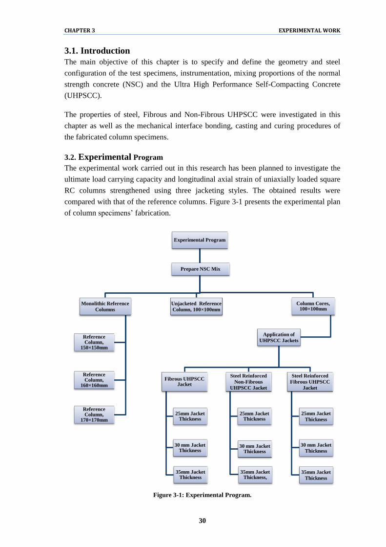
CHAPTER 3 EXPERIMENTAL WORK
30
3.1. Introduction
The main objective of this chapter is to specify and define the geometry and steel
configuration of the test specimens, instrumentation, mixing proportions of the normal
strength concrete (NSC) and the Ultra High Performance Self-Compacting Concrete
(UHPSCC).
The properties of steel, Fibrous and Non-Fibrous UHPSCC were investigated in this
chapter as well as the mechanical interface bonding, casting and curing procedures of
the fabricated column specimens.
3.2. Experimental Program
The experimental work carried out in this research has been planned to investigate the
ultimate load carrying capacity and longitudinal axial strain of uniaxially loaded square
RC columns strengthened using three jacketing styles. The obtained results were
compared with that of the reference columns. Figure 3-1 presents the experimental plan
of column specimens’ fabrication.
Figure 3-1: Experimental Program.
Experimental Program
Unjacketed Reference
Column, 100×100mm
Monolithic Reference
Columns
Reference Column,
150×150mm
Reference Column,
160×160mm
Reference Column,
170×170mm
Column Cores, 100×100mm
Application of
UHPSCC Jackets
Fibrous UHPSCC Jacket
25mm Jacket Thickness
30 mm Jacket Thickness
35mm Jacket Thickness
Steel Reinforced
Non-Fibrous
UHPSCC Jacket
25mm Jacket Thickness
30 mm Jacket Thickness
35mm Jacket Thickness,
Steel Reinforced
Fibrous UHPSCC
Jacket
25mm Jacket
Thickness
30 mm Jacket
Thickness
35mm Jacket
Thickness
Prepare NSC Mix
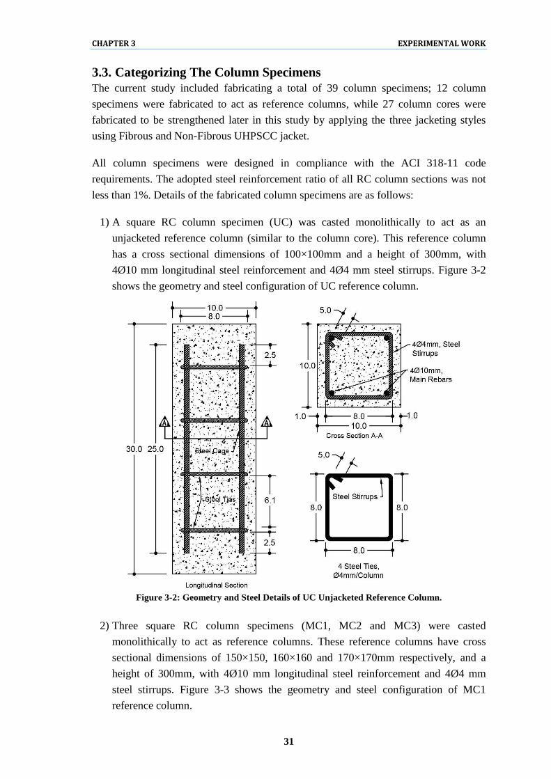
CHAPTER 3 EXPERIMENTAL WORK
31
3.3. Categorizing The Column Specimens
The current study included fabricating a total of 39 column specimens; 12 column
specimens were fabricated to act as reference columns, while 27 column cores were
fabricated to be strengthened later in this study by applying the three jacketing styles
using Fibrous and Non-Fibrous UHPSCC jacket.
All column specimens were designed in compliance with the ACI 318-11 code
requirements. The adopted steel reinforcement ratio of all RC column sections was not
less than 1%. Details of the fabricated column specimens are as follows:
1) A square RC column specimen (UC) was casted monolithically to act as an
unjacketed reference column (similar to the column core). This reference column
has a cross sectional dimensions of 100×100mm and a height of 300mm, with
4Ø10 mm longitudinal steel reinforcement and 4Ø4 mm steel stirrups. Figure 3-2
shows the geometry and steel configuration of UC reference column.
Figure 3-2: Geometry and Steel Details of UC Unjacketed Reference Column.
2) Three square RC column specimens (MC1, MC2 and MC3) were casted
monolithically to act as reference columns. These reference columns have cross
sectional dimensions of 150×150, 160×160 and 170×170mm respectively, and a
height of 300mm, with 4Ø10 mm longitudinal steel reinforcement and 4Ø4 mm
steel stirrups. Figure 3-3 shows the geometry and steel configuration of MC1
reference column.
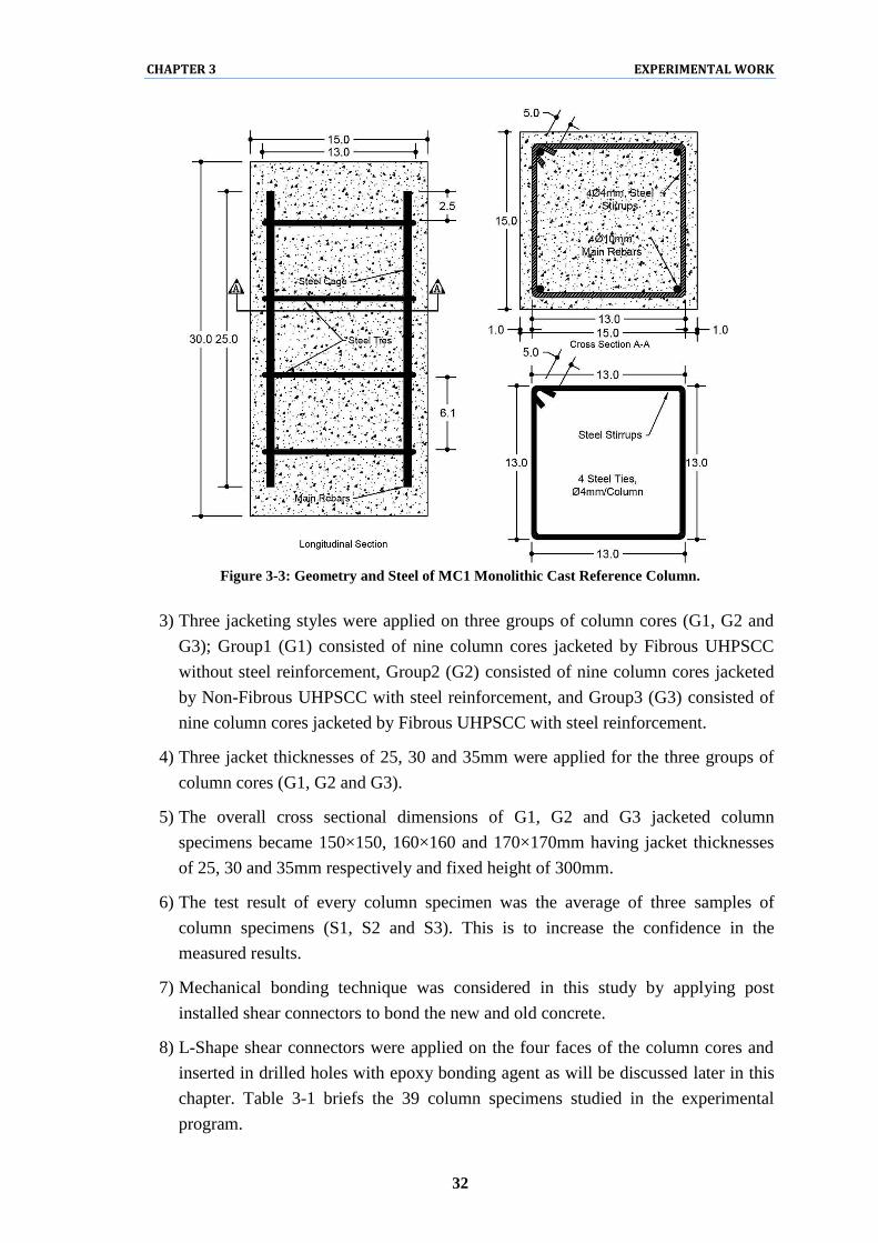
CHAPTER 3 EXPERIMENTAL WORK
32
Figure 3-3: Geometry and Steel of MC1 Monolithic Cast Reference Column.
3) Three jacketing styles were applied on three groups of column cores (G1, G2 and
G3); Group1 (G1) consisted of nine column cores jacketed by Fibrous UHPSCC
without steel reinforcement, Group2 (G2) consisted of nine column cores jacketed
by Non-Fibrous UHPSCC with steel reinforcement, and Group3 (G3) consisted of
nine column cores jacketed by Fibrous UHPSCC with steel reinforcement.
4) Three jacket thicknesses of 25, 30 and 35mm were applied for the three groups of
column cores (G1, G2 and G3).
5) The overall cross sectional dimensions of G1, G2 and G3 jacketed column
specimens became 150×150, 160×160 and 170×170mm having jacket thicknesses
of 25, 30 and 35mm respectively and fixed height of 300mm.
6) The test result of every column specimen was the average of three samples of
column specimens (S1, S2 and S3). This is to increase the confidence in the
measured results.
7) Mechanical bonding technique was considered in this study by applying post
installed shear connectors to bond the new and old concrete.
8) L-Shape shear connectors were applied on the four faces of the column cores and
inserted in drilled holes with epoxy bonding agent as will be discussed later in this
chapter. Table 3-1 briefs the 39 column specimens studied in the experimental
program.
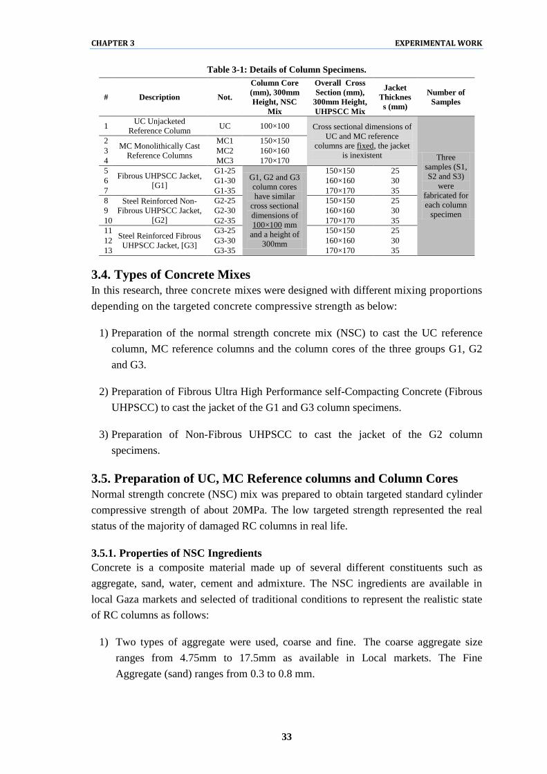
CHAPTER 3 EXPERIMENTAL WORK
33
Table 3-1: Details of Column Specimens.
# Description Not.
Column Core
(mm), 300mm
Height, NSC
Mix
Overall Cross
Section (mm),
300mm Height,
UHPSCC Mix
Jacket
Thicknes
s (mm)
Number of
Samples
1 UC Unjacketed
Reference Column UC 100×100 Cross sectional dimensions of
UC and MC reference
columns are fixed, the jacket
is inexistent Three
samples (S1,
S2 and S3)
were
fabricated for
each column
specimen
2 MC Monolithically Cast
Reference Columns
MC1 150×150
3 MC2 160×160
4 MC3 170×170
5 Fibrous UHPSCC Jacket,
[G1]
G1-25 G1, G2 and G3
column cores
have similar
cross sectional
dimensions of
100×100 mm
and a height of
300mm
150×150 25
6 G1-30 160×160 30
7 G1-35 170×170 35
8 Steel Reinforced Non-
Fibrous UHPSCC Jacket,
[G2]
G2-25 150×150 25
9 G2-30 160×160 30
10 G2-35 170×170 35
11 Steel Reinforced Fibrous
UHPSCC Jacket, [G3]
G3-25 150×150 25
12 G3-30 160×160 30
13 G3-35 170×170 35
3.4. Types of Concrete Mixes
In this research, three concrete mixes were designed with different mixing proportions
depending on the targeted concrete compressive strength as below:
1) Preparation of the normal strength concrete mix (NSC) to cast the UC reference
column, MC reference columns and the column cores of the three groups G1, G2
and G3.
2) Preparation of Fibrous Ultra High Performance self-Compacting Concrete (Fibrous
UHPSCC) to cast the jacket of the G1 and G3 column specimens.
3) Preparation of Non-Fibrous UHPSCC to cast the jacket of the G2 column
specimens.
3.5. Preparation of UC, MC Reference columns and Column Cores
Normal strength concrete (NSC) mix was prepared to obtain targeted standard cylinder
compressive strength of about 20MPa. The low targeted strength represented the real
status of the majority of damaged RC columns in real life.
Properties of NSC Ingredients 3.5.1.
Concrete is a composite material made up of several different constituents such as
aggregate, sand, water, cement and admixture. The NSC ingredients are available in
local Gaza markets and selected of traditional conditions to represent the realistic state
of RC columns as follows:
1) Two types of aggregate were used, coarse and fine. The coarse aggregate size
ranges from 4.75mm to 17.5mm as available in Local markets. The Fine
Aggregate (sand) ranges from 0.3 to 0.8 mm.
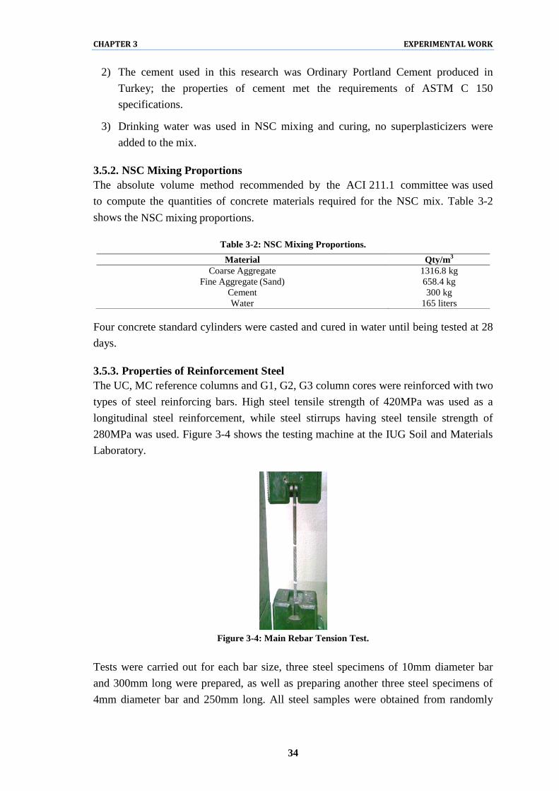
CHAPTER 3 EXPERIMENTAL WORK
34
2) The cement used in this research was Ordinary Portland Cement produced in
Turkey; the properties of cement met the requirements of ASTM C 150
specifications.
3) Drinking water was used in NSC mixing and curing, no superplasticizers were
added to the mix.
NSC Mixing Proportions 3.5.2.
The absolute volume method recommended by the ACI 211.1 committee was used
to compute the quantities of concrete materials required for the NSC mix. Table 3-2
shows the NSC mixing proportions.
Table 3-2: NSC Mixing Proportions.
Four concrete standard cylinders were casted and cured in water until being tested at 28
days.
Properties of Reinforcement Steel 3.5.3.
The UC, MC reference columns and G1, G2, G3 column cores were reinforced with two
types of steel reinforcing bars. High steel tensile strength of 420MPa was used as a
longitudinal steel reinforcement, while steel stirrups having steel tensile strength of
280MPa was used. Figure 3-4 shows the testing machine at the IUG Soil and Materials
Laboratory.
Figure 3-4: Main Rebar Tension Test.
Tests were carried out for each bar size, three steel specimens of 10mm diameter bar
and 300mm long were prepared, as well as preparing another three steel specimens of
4mm diameter bar and 250mm long. All steel samples were obtained from randomly
Material Qty/m3
Coarse Aggregate 1316.8 kg
Fine Aggregate (Sand) 658.4 kg
Cement 300 kg
Water 165 liters
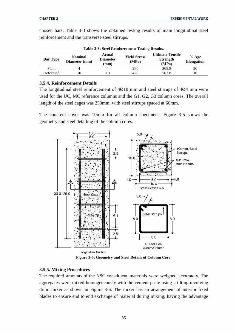
CHAPTER 3 EXPERIMENTAL WORK
35
chosen bars. Table 3-3 shows the obtained testing results of main longitudinal steel
reinforcement and the transverse steel stirrups.
Table 3-3: Steel Reinforcement Testing Results.
Bar Type Nominal
Diameter (mm)
Actual
Diameter
(mm)
Yield Stress
(MPa)
Ultimate Tensile
Strength
(MPa)
% Age
Elongation
Plain 4 4 280 365.8 26
Deformed 10 10 420 562.8 16
Reinforcement Details 3.5.4.
The longitudinal steel reinforcement of 4Ø10 mm and steel stirrups of 4Ø4 mm were
used for the UC, MC reference columns and the G1, G2, G3 column cores. The overall
length of the steel cages was 250mm, with steel stirrups spaced at 60mm.
The concrete cover was 10mm for all column specimens. Figure 3-5 shows the
geometry and steel detailing of the column cores.
Figure 3-5: Geometry and Steel Details of Column Core.
Mixing Procedures 3.5.5.
The required amounts of the NSC constituent materials were weighed accurately. The
aggregates were mixed homogeneously with the cement paste using a tilting revolving
drum mixer as shown in Figure 3-6. The mixer has an arrangement of interior fixed
blades to ensure end to end exchange of material during mixing, having the advantage
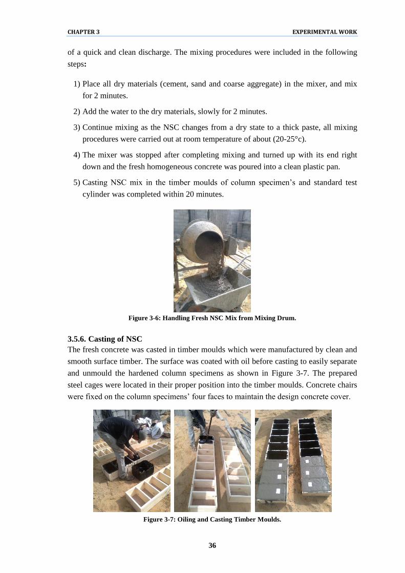
CHAPTER 3 EXPERIMENTAL WORK
36
of a quick and clean discharge. The mixing procedures were included in the following
steps:
1) Place all dry materials (cement, sand and coarse aggregate) in the mixer, and mix
for 2 minutes.
2) Add the water to the dry materials, slowly for 2 minutes.
3) Continue mixing as the NSC changes from a dry state to a thick paste, all mixing
procedures were carried out at room temperature of about (20-25°c).
4) The mixer was stopped after completing mixing and turned up with its end right
down and the fresh homogeneous concrete was poured into a clean plastic pan.
5) Casting NSC mix in the timber moulds of column specimen’s and standard test
cylinder was completed within 20 minutes.
Figure 3-6: Handling Fresh NSC Mix from Mixing Drum.
Casting of NSC 3.5.6.
The fresh concrete was casted in timber moulds which were manufactured by clean and
smooth surface timber. The surface was coated with oil before casting to easily separate
and unmould the hardened column specimens as shown in Figure 3-7. The prepared
steel cages were located in their proper position into the timber moulds. Concrete chairs
were fixed on the column specimens’ four faces to maintain the design concrete cover.
Figure 3-7: Oiling and Casting Timber Moulds.
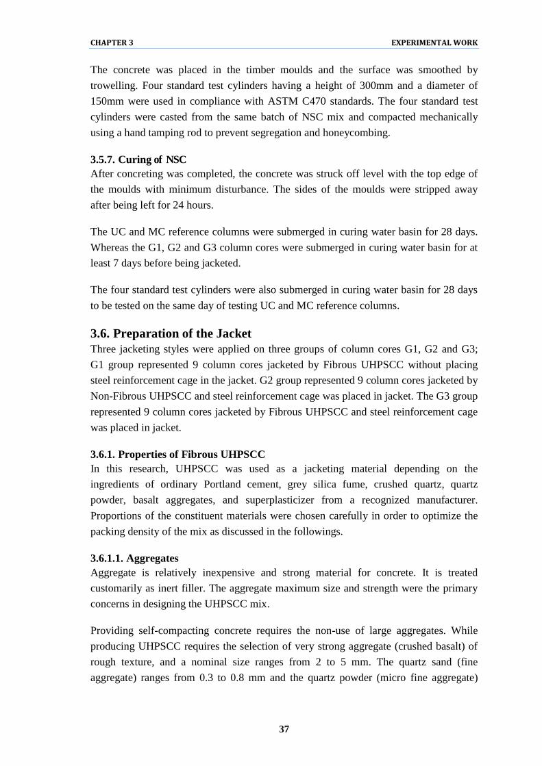
CHAPTER 3 EXPERIMENTAL WORK
37
The concrete was placed in the timber moulds and the surface was smoothed by
trowelling. Four standard test cylinders having a height of 300mm and a diameter of
150mm were used in compliance with ASTM C470 standards. The four standard test
cylinders were casted from the same batch of NSC mix and compacted mechanically
using a hand tamping rod to prevent segregation and honeycombing.
Curing of NSC 3.5.7.
After concreting was completed, the concrete was struck off level with the top edge of
the moulds with minimum disturbance. The sides of the moulds were stripped away
after being left for 24 hours.
The UC and MC reference columns were submerged in curing water basin for 28 days.
Whereas the G1, G2 and G3 column cores were submerged in curing water basin for at
least 7 days before being jacketed.
The four standard test cylinders were also submerged in curing water basin for 28 days
to be tested on the same day of testing UC and MC reference columns.
3.6. Preparation of the Jacket
Three jacketing styles were applied on three groups of column cores G1, G2 and G3;
G1 group represented 9 column cores jacketed by Fibrous UHPSCC without placing
steel reinforcement cage in the jacket. G2 group represented 9 column cores jacketed by
Non-Fibrous UHPSCC and steel reinforcement cage was placed in jacket. The G3 group
represented 9 column cores jacketed by Fibrous UHPSCC and steel reinforcement cage
was placed in jacket.
Properties of Fibrous UHPSCC 3.6.1.
In this research, UHPSCC was used as a jacketing material depending on the
ingredients of ordinary Portland cement, grey silica fume, crushed quartz, quartz
powder, basalt aggregates, and superplasticizer from a recognized manufacturer.
Proportions of the constituent materials were chosen carefully in order to optimize the
packing density of the mix as discussed in the followings.
Aggregates 3.6.1.1.
Aggregate is relatively inexpensive and strong material for concrete. It is treated
customarily as inert filler. The aggregate maximum size and strength were the primary
concerns in designing the UHPSCC mix.
Providing self-compacting concrete requires the non-use of large aggregates. While
producing UHPSCC requires the selection of very strong aggregate (crushed basalt) of
rough texture, and a nominal size ranges from 2 to 5 mm. The quartz sand (fine
aggregate) ranges from 0.3 to 0.8 mm and the quartz powder (micro fine aggregate)
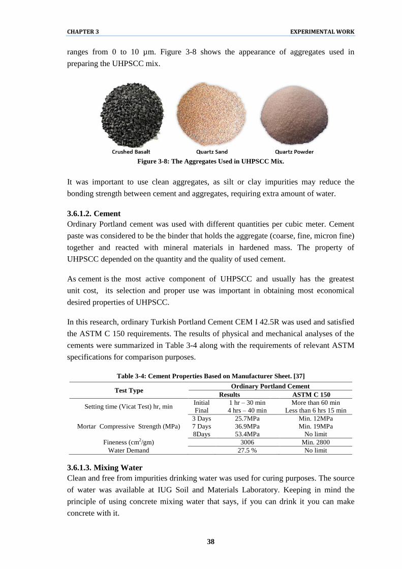
CHAPTER 3 EXPERIMENTAL WORK
38
ranges from 0 to 10 µm. Figure 3-8 shows the appearance of aggregates used in
preparing the UHPSCC mix.
Figure 3-8: The Aggregates Used in UHPSCC Mix.
It was important to use clean aggregates, as silt or clay impurities may reduce the
bonding strength between cement and aggregates, requiring extra amount of water.
Cement 3.6.1.2.
Ordinary Portland cement was used with different quantities per cubic meter. Cement
paste was considered to be the binder that holds the aggregate (coarse, fine, micron fine)
together and reacted with mineral materials in hardened mass. The property of
UHPSCC depended on the quantity and the quality of used cement.
As cement is the most active component of UHPSCC and usually has the greatest
unit cost, its selection and proper use was important in obtaining most economical
desired properties of UHPSCC.
In this research, ordinary Turkish Portland Cement CEM I 42.5R was used and satisfied
the ASTM C 150 requirements. The results of physical and mechanical analyses of the
cements were summarized in Table 3-4 along with the requirements of relevant ASTM
specifications for comparison purposes.
Table 3-4: Cement Properties Based on Manufacturer Sheet.[37]
Test Type Ordinary Portland Cement
Results ASTM C 150
Setting time (Vicat Test) hr, min Initial 1 hr – 30 min More than 60 min
Final 4 hrs – 40 min Less than 6 hrs 15 min
Mortar Compressive Strength (MPa)
3 Days 25.7MPa Min. 12MPa
7 Days 36.9MPa Min. 19MPa
8Days 53.4MPa No limit
Fineness (cm2/gm) 3006 Min. 2800
Water Demand 27.5 % No limit
Mixing Water 3.6.1.3.
Clean and free from impurities drinking water was used for curing purposes. The source
of water was available at IUG Soil and Materials Laboratory. Keeping in mind the
principle of using concrete mixing water that says, if you can drink it you can make
concrete with it.
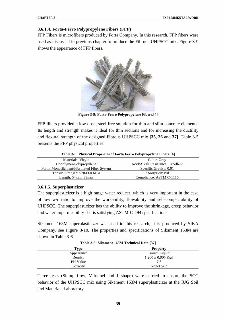
CHAPTER 3 EXPERIMENTAL WORK
39
Forta-Ferro Polypropylene Fibers (FFP) 3.6.1.4.
FFP Fibers is microfibers produced by Forta Company. In this research, FFP fibers were
used as discussed in previous chapter to produce the Fibrous UHPSCC mix. Figure 3-9
shows the appearance of FFP fibers.
Figure 3-9: Forta-Ferro Polypropylene Fibers.[4]
FFP fibers provided a low dose, steel free solution for thin and slim concrete elements.
Its length and strength makes it ideal for thin sections and for increasing the ductility
and flexural strength of the designed Fibrous UHPSCC mix [35, 36 and 37]. Table 3-5
presents the FFP physical properties.
Table 3-5: Physical Properties of Forta Ferro Polypropylene Fibers.[4]
Materials: Virgin
Copolymer/Polypropylene
Form: Monofilament/Fibrillated Fiber System
Color: Gray
Acid/Alkali Resistance: Excellent
Specific Gravity: 0.91
Tensile Strength: 570-660 MPa
Length: 54mm, 38mm
Absorption: Nil
Compliance: ASTM C-1116
Superplasticizer 3.6.1.5.
The superplasticizer is a high range water reducer, which is very important in the case
of low w/c ratio to improve the workability, flowability and self-compactability of
UHPSCC. The superplasticizer has the ability to improve the shrinkage, creep behavior
and water impermeability if it is satisfying ASTM-C-494 specifications.
Sikament 163M superplasticizer was used in this research, it is produced by SIKA
Company, see Figure 3-10. The properties and specifications of Sikament 163M are
shown in Table 3-6.
Table 3-6: Sikament 163M Technical Data.[37]
Type Property
Appearance Brown Liquid
Density 1.200 ± 0.005 Kg/l
PH Value 7.5
Toxicity Non-Toxic
Three tests (Slump flow, V-funnel and L-shape) were carried to ensure the SCC
behavior of the UHPSCC mix using Sikament 163M superplasticizer at the IUG Soil
and Materials Laboratory.

CHAPTER 3 EXPERIMENTAL WORK
40
Figure 3-10: Sikament 163M Superplasticizer.
The results obtained were satisfying the fresh properties standards developed by the
European Guidelines of self-compacting concrete (EFNARC) as presented in Table 3-7.
Table 3-7: Self-Compacting Properties of UHPSCC Mix.
Method Unit Obtained Results
Slump flow (Abram Cone) mm 563
V- funnel S 9.7
L – Box (h2/h1) - 0.82
Silica Fume 3.6.1.6.
Silica fume is a byproduct resulting from the reduction of high-purity quartz with coal
or coke and wood chips in an electric arc furnace during the production of silicon metal
or ferrosilicon alloys.
The silica fume which condenses from the gases escaping from the furnaces has a very
high content of amorphous silicon dioxide and consists of very fine spherical particles
(ACI 548.6R-96). Figure 3-11 shows the silica fume appearance.
Figure 3-11: Silica Fume Appearance
Sika-Fume was used in this research as a silica fume produced by SIKA Company.
Table 3-8 presents the technical data of the Sika-Fume.
Table 3-8: Sika-Fume Properties.[37]
Type Property
Appearance Grey powder
Specific gravity 2.20
Chloride content Nil
Toxicity Non-toxic
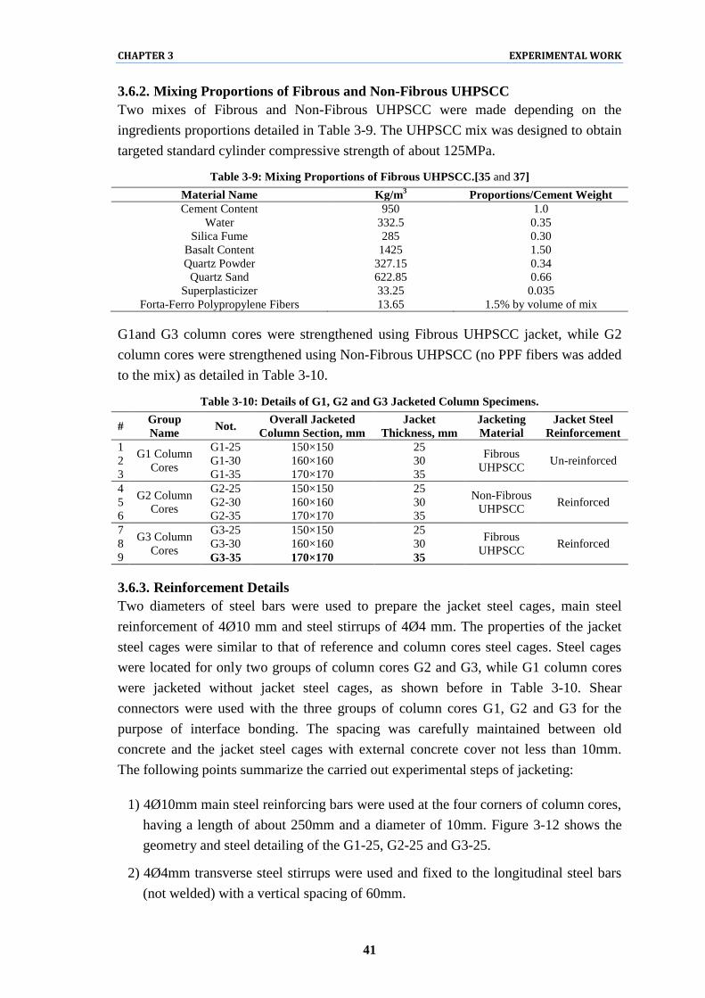
CHAPTER 3 EXPERIMENTAL WORK
41
Mixing Proportions of Fibrous and Non-Fibrous UHPSCC 3.6.2.
Two mixes of Fibrous and Non-Fibrous UHPSCC were made depending on the
ingredients proportions detailed in Table 3-9. The UHPSCC mix was designed to obtain
targeted standard cylinder compressive strength of about 125MPa.
Table 3-9: Mixing Proportions of Fibrous UHPSCC.[35 and 37]
Material Name Kg/m3 Proportions/Cement Weight
Cement Content 950 1.0
Water 332.5 0.35
Silica Fume 285 0.30
Basalt Content 1425 1.50
Quartz Powder 327.15 0.34
Quartz Sand 622.85 0.66
Superplasticizer 33.25 0.035
Forta-Ferro Polypropylene Fibers 13.65 1.5% by volume of mix
G1and G3 column cores were strengthened using Fibrous UHPSCC jacket, while G2
column cores were strengthened using Non-Fibrous UHPSCC (no PPF fibers was added
to the mix) as detailed in Table 3-10.
Table 3-10: Details of G1, G2 and G3 Jacketed Column Specimens.
# Group
Name Not.
Overall Jacketed
Column Section, mm
Jacket
Thickness, mm
Jacketing
Material
Jacket Steel
Reinforcement
1 G1 Column
Cores
G1-25 150×150 25 Fibrous
UHPSCC
2 G1-30 160×160 30 Un-reinforced
3 G1-35 170×170 35
4 G2 Column
Cores
G2-25 150×150 25 Non-Fibrous
UHPSCC
5 G2-30 160×160 30 Reinforced
6 G2-35 170×170 35
7 G3 Column
Cores
G3-25 150×150 25 Fibrous
UHPSCC
8 G3-30 160×160 30 Reinforced
9 G3-35 170×170 35
Reinforcement Details 3.6.3.
Two diameters of steel bars were used to prepare the jacket steel cages, main steel
reinforcement of 4Ø10 mm and steel stirrups of 4Ø4 mm. The properties of the jacket
steel cages were similar to that of reference and column cores steel cages. Steel cages
were located for only two groups of column cores G2 and G3, while G1 column cores
were jacketed without jacket steel cages, as shown before in Table 3-10. Shear
connectors were used with the three groups of column cores G1, G2 and G3 for the
purpose of interface bonding. The spacing was carefully maintained between old
concrete and the jacket steel cages with external concrete cover not less than 10mm.
The following points summarize the carried out experimental steps of jacketing:
1) 4Ø10mm main steel reinforcing bars were used at the four corners of column cores,
having a length of about 250mm and a diameter of 10mm. Figure 3-12 shows the
geometry and steel detailing of the G1-25, G2-25 and G3-25.
2) 4Ø4mm transverse steel stirrups were used and fixed to the longitudinal steel bars
(not welded) with a vertical spacing of 60mm.
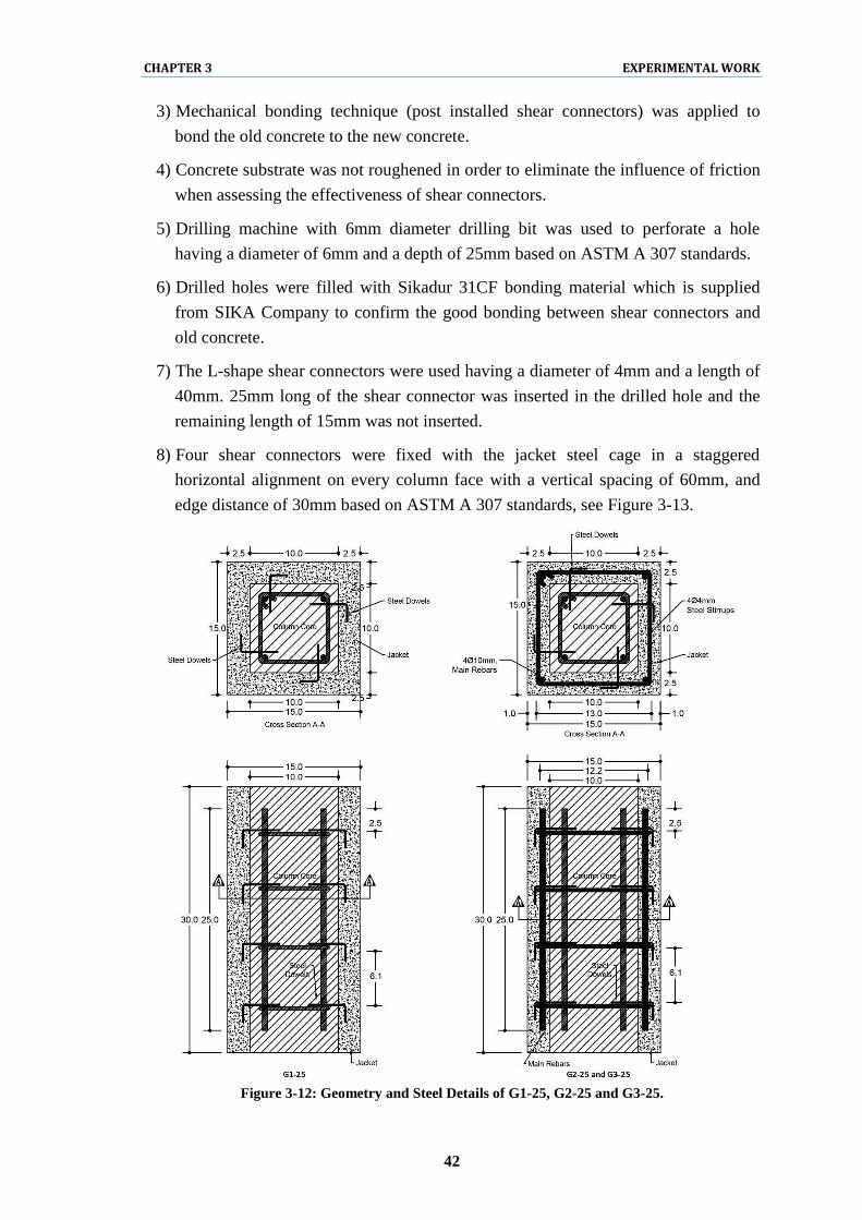
CHAPTER 3 EXPERIMENTAL WORK
42
3) Mechanical bonding technique (post installed shear connectors) was applied to
bond the old concrete to the new concrete.
4) Concrete substrate was not roughened in order to eliminate the influence of friction
when assessing the effectiveness of shear connectors.
5) Drilling machine with 6mm diameter drilling bit was used to perforate a hole
having a diameter of 6mm and a depth of 25mm based on ASTM A 307 standards.
6) Drilled holes were filled with Sikadur 31CF bonding material which is supplied
from SIKA Company to confirm the good bonding between shear connectors and
old concrete.
7) The L-shape shear connectors were used having a diameter of 4mm and a length of
40mm. 25mm long of the shear connector was inserted in the drilled hole and the
remaining length of 15mm was not inserted.
8) Four shear connectors were fixed with the jacket steel cage in a staggered
horizontal alignment on every column face with a vertical spacing of 60mm, and
edge distance of 30mm based on ASTM A 307 standards, see Figure 3-13.
Figure 3-12: Geometry and Steel Details of G1-25, G2-25 and G3-25.

CHAPTER 3 EXPERIMENTAL WORK
43
Figure 3-13: Shear Connectors and Bonding Agent.
Mixing Procedures 3.6.4.
Fibrous and Non-Fibrous UHPSCC mixes were made at IUG Soil and Material
laboratory. All required amounts of constituent materials were weighed accurately and
mixed properly to produce homogeneous concrete mass using the same tilting revolving
drum mixer. The mixing procedures were included in the following steps:
1) Add 40 % of superplasticizer to the mixing water.
2) Place all dry materials (cement, silica fume, crushed quartz and aggregate) with
50% of the FFP fibers in the drum mixer, and mix for minimum 2 minutes.
3) Place the mixing water (with 40% of superplasticizer) to the dry materials, slowly
for 2 minutes.
4) Wait for a minute while the drum is revolving then add the remaining
superplasticizer to the batch for 30 seconds.
5) Continue mixing for 5 minutes and add the remaining 50% of the FFP fibers,
noting that the Fibrous UHPSCC start changing from dry state to a thick paste.
6) The mixer was stopped after completing mixing, turned up with its end right
down, and the fresh homogeneous concrete was poured into a clean plastic pan.
7) The mix casting should be completed within not more than 20 minutes.
All the above mentioned steps were repeated again to prepare the Non-Fibrous
UHPSCC mix.
Casting of UHPSCC 3.6.5.
The fresh Fibrous UHPSCC was casted in the timber moulds of the G1 and G3 column
cores. Timber moulds were manufactured with very accurate dimensions based on the
required jacket thickness, and made of hard, clean and smooth surface timber. The
surface was coated with oil before casting to easily separate and unmould hardened
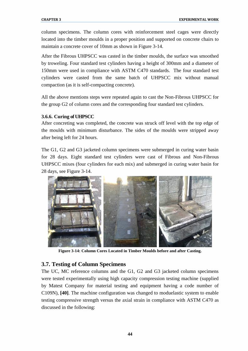
CHAPTER 3 EXPERIMENTAL WORK
44
column specimens. The column cores with reinforcement steel cages were directly
located into the timber moulds in a proper position and supported on concrete chairs to
maintain a concrete cover of 10mm as shown in Figure 3-14.
After the Fibrous UHPSCC was casted in the timber moulds, the surface was smoothed
by troweling. Four standard test cylinders having a height of 300mm and a diameter of
150mm were used in compliance with ASTM C470 standards. The four standard test
cylinders were casted from the same batch of UHPSCC mix without manual
compaction (as it is self-compacting concrete).
All the above mentions steps were repeated again to cast the Non-Fibrous UHPSCC for
the group G2 of column cores and the corresponding four standard test cylinders.
Curing of UHPSCC 3.6.6.
After concreting was completed, the concrete was struck off level with the top edge of
the moulds with minimum disturbance. The sides of the moulds were stripped away
after being left for 24 hours.
The G1, G2 and G3 jacketed column specimens were submerged in curing water basin
for 28 days. Eight standard test cylinders were cast of Fibrous and Non-Fibrous
UHPSCC mixes (four cylinders for each mix) and submerged in curing water basin for
28 days, see Figure 3-14.
Figure 3-14: Column Cores Located in Timber Moulds before and after Casting.
3.7. Testing of Column Specimens
The UC, MC reference columns and the G1, G2 and G3 jacketed column specimens
were tested experimentally using high capacity compression testing machine (supplied
by Matest Company for material testing and equipment having a code number of
C109N), [40]. The machine configuration was changed to moduelastic system to enable
testing compressive strength versus the axial strain in compliance with ASTM C470 as
discussed in the following:

CHAPTER 3 EXPERIMENTAL WORK
45
The Ultimate Load Carrying Capacity of Column Specimens 3.7.1.
After ending the curing period, the UC, MC reference columns and G1, G2, G3 jacketed
column specimens were kept in dry place for 10 to15 minutes to attain surface dry
condition. Loose sand grains or incrustations were removed from contact faces with
testing machine platens.
The column specimens were then located carefully in the testing machine in order to
ensure the vertical concentricity (uniaxial) of the applied compressive load. Thereafter,
test was carried out by the hydraulic machine with 3000KN compression testing
capacity.
All column specimens were tested under monotonically small loading rate of about 6
KN/sec and a starting load of about 20 KN. The load was applied vertically at the top
and bottom of the column specimens until failure and compression readings were
collected.
The Longitudinal Axial Strain of Column Specimens 3.7.2.
Longitudinal axial strains of UC, MC reference columns and G1, G2, G3 jacketed
column specimens were measured using the same compression testing machine. Three
strain dial gauges (also called transducers) within accuracy of about 0.00254 mm were
fixed at the mid height of the column three faces prior to testing as shown Figure 3-15.
At each increment of 6 KN axial compression load, readings of longitudinal axial strain
were recorded using the machine data acquisition system.
Figure 3-15: The Compression Testing Machine

CHAPTER 4RESULTS & DISCUSSION
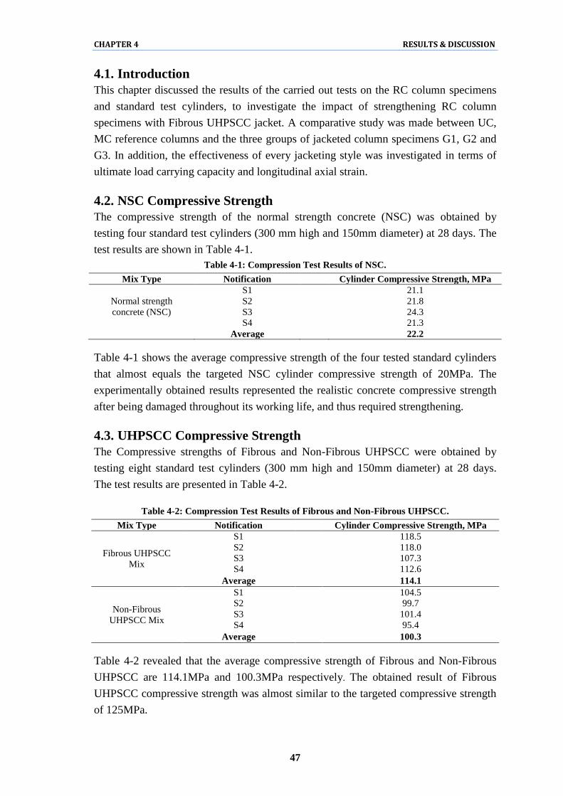
CHAPTER 4 RESULTS & DISCUSSION
47
4.1. Introduction
This chapter discussed the results of the carried out tests on the RC column specimens
and standard test cylinders, to investigate the impact of strengthening RC column
specimens with Fibrous UHPSCC jacket. A comparative study was made between UC,
MC reference columns and the three groups of jacketed column specimens G1, G2 and
G3. In addition, the effectiveness of every jacketing style was investigated in terms of
ultimate load carrying capacity and longitudinal axial strain.
4.2. NSC Compressive Strength
The compressive strength of the normal strength concrete (NSC) was obtained by
testing four standard test cylinders (300 mm high and 150mm diameter) at 28 days. The
test results are shown in Table 4-1.
Table 4-1: Compression Test Results of NSC.
Mix Type Notification Cylinder Compressive Strength, MPa
Normal strength
concrete (NSC)
S1 21.1
S2 21.8
S3 24.3
S4 21.3
Average 22.2
Table 4-1 shows the average compressive strength of the four tested standard cylinders
that almost equals the targeted NSC cylinder compressive strength of 20MPa. The
experimentally obtained results represented the realistic concrete compressive strength
after being damaged throughout its working life, and thus required strengthening.
4.3. UHPSCC Compressive Strength
The Compressive strengths of Fibrous and Non-Fibrous UHPSCC were obtained by
testing eight standard test cylinders (300 mm high and 150mm diameter) at 28 days.
The test results are presented in Table 4-2.
Table 4-2: Compression Test Results of Fibrous and Non-Fibrous UHPSCC.
Mix Type Notification Cylinder Compressive Strength, MPa
Fibrous UHPSCC
Mix
S1 118.5
S2 118.0
S3 107.3
S4 112.6
Average 114.1
Non-Fibrous
UHPSCC Mix
S1 104.5
S2 99.7
S3 101.4
S4 95.4
Average 100.3
Table 4-2 revealed that the average compressive strength of Fibrous and Non-Fibrous
UHPSCC are 114.1MPa and 100.3MPa respectively. The obtained result of Fibrous
UHPSCC compressive strength was almost similar to the targeted compressive strength
of 125MPa.
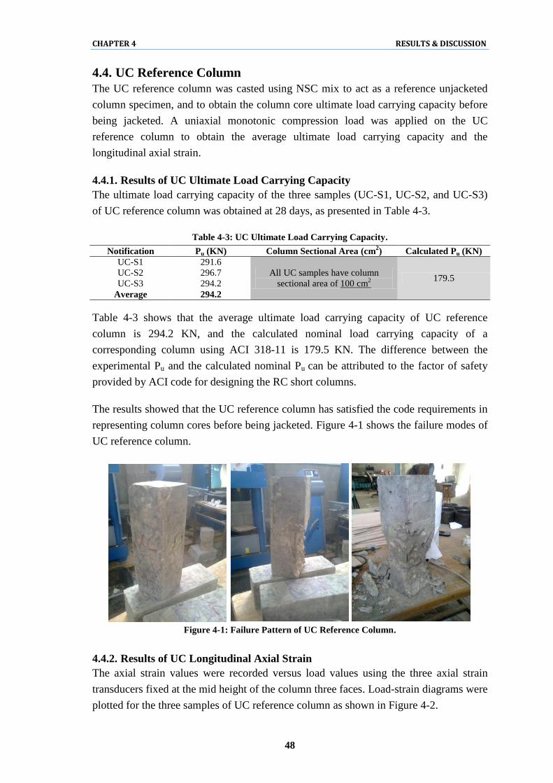
CHAPTER 4 RESULTS & DISCUSSION
48
4.4. UC Reference Column
The UC reference column was casted using NSC mix to act as a reference unjacketed
column specimen, and to obtain the column core ultimate load carrying capacity before
being jacketed. A uniaxial monotonic compression load was applied on the UC
reference column to obtain the average ultimate load carrying capacity and the
longitudinal axial strain.
Results of UC Ultimate Load Carrying Capacity 4.4.1.
The ultimate load carrying capacity of the three samples (UC-S1, UC-S2, and UC-S3)
of UC reference column was obtained at 28 days, as presented in Table 4-3.
Table 4-3: UC Ultimate Load Carrying Capacity.
Notification Pu (KN) Column Sectional Area (cm2) Calculated Pu (KN)
UC-S1 291.6
All UC samples have column
sectional area of 100 cm2
179.5 UC-S2 296.7
UC-S3 294.2
Average 294.2
Table 4-3 shows that the average ultimate load carrying capacity of UC reference
column is 294.2 KN, and the calculated nominal load carrying capacity of a
corresponding column using ACI 318-11 is 179.5 KN. The difference between the
experimental Pu and the calculated nominal Pu can be attributed to the factor of safety
provided by ACI code for designing the RC short columns.
The results showed that the UC reference column has satisfied the code requirements in
representing column cores before being jacketed. Figure 4-1 shows the failure modes of
UC reference column.
Figure 4-1: Failure Pattern of UC Reference Column.
Results of UC Longitudinal Axial Strain 4.4.2.
The axial strain values were recorded versus load values using the three axial strain
transducers fixed at the mid height of the column three faces. Load-strain diagrams were
plotted for the three samples of UC reference column as shown in Figure 4-2.
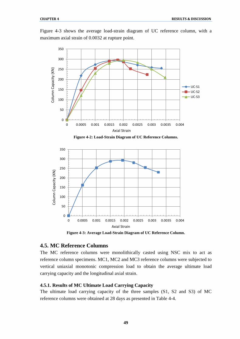
CHAPTER 4 RESULTS & DISCUSSION
49
Figure 4-3 shows the average load-strain diagram of UC reference column, with a
maximum axial strain of 0.0032 at rupture point.
Figure 4-2: Load-Strain Diagram of UC Reference Columns.
Figure 4-3: Average Load-Strain Diagram of UC Reference Column.
4.5. MC Reference Columns
The MC reference columns were monolithically casted using NSC mix to act as
reference column specimens. MC1, MC2 and MC3 reference columns were subjected to
vertical uniaxial monotonic compression load to obtain the average ultimate load
carrying capacity and the longitudinal axial strain.
Results of MC Ultimate Load Carrying Capacity 4.5.1.
The ultimate load carrying capacity of the three samples (S1, S2 and S3) of MC
reference columns were obtained at 28 days as presented in Table 4-4.
0
50
100
150
200
250
300
350
0 0.0005 0.001 0.0015 0.002 0.0025 0.003 0.0035 0.004
Co
lum
n C
apac
ity
(KN
)
Axial Strain
UC-S1
UC-S2
UC-S3
0
50
100
150
200
250
300
350
0 0.0005 0.001 0.0015 0.002 0.0025 0.003 0.0035 0.004
Co
lum
n C
apac
ity
(KN
)
Axial Strain
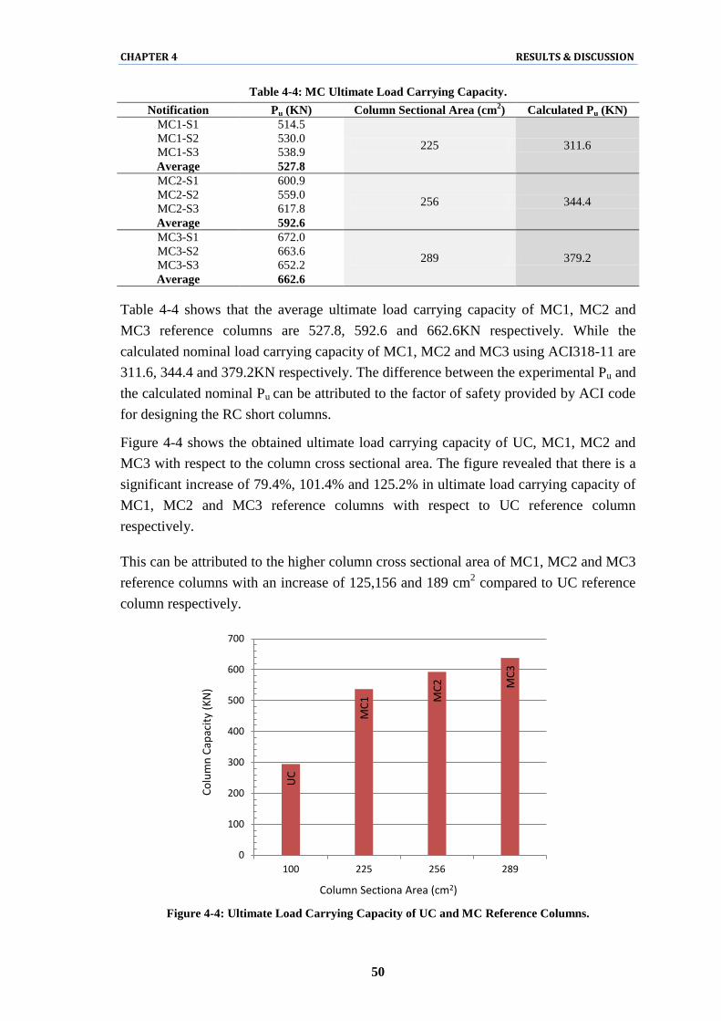
CHAPTER 4 RESULTS & DISCUSSION
50
Table 4-4: MC Ultimate Load Carrying Capacity.
Notification Pu (KN) Column Sectional Area (cm2) Calculated Pu (KN)
MC1-S1 514.5
225 311.6 MC1-S2 530.0
MC1-S3 538.9
Average 527.8
MC2-S1 600.9
256 344.4 MC2-S2 559.0
MC2-S3 617.8
Average 592.6
MC3-S1 672.0
289 379.2 MC3-S2 663.6
MC3-S3 652.2
Average 662.6
Table 4-4 shows that the average ultimate load carrying capacity of MC1, MC2 and
MC3 reference columns are 527.8, 592.6 and 662.6KN respectively. While the
calculated nominal load carrying capacity of MC1, MC2 and MC3 using ACI318-11 are
311.6, 344.4 and 379.2KN respectively. The difference between the experimental Pu and
the calculated nominal Pu can be attributed to the factor of safety provided by ACI code
for designing the RC short columns.
Figure 4-4 shows the obtained ultimate load carrying capacity of UC, MC1, MC2 and
MC3 with respect to the column cross sectional area. The figure revealed that there is a
significant increase of 79.4%, 101.4% and 125.2% in ultimate load carrying capacity of
MC1, MC2 and MC3 reference columns with respect to UC reference column
respectively.
This can be attributed to the higher column cross sectional area of MC1, MC2 and MC3
reference columns with an increase of 125,156 and 189 cm2 compared to UC reference
column respectively.
Figure 4-4: Ultimate Load Carrying Capacity of UC and MC Reference Columns.
UC
MC
1 MC
2
MC
3
0
100
200
300
400
500
600
700
100 225 256 289
Co
lum
n C
apac
ity
(KN
)
Column Sectiona Area (cm2)
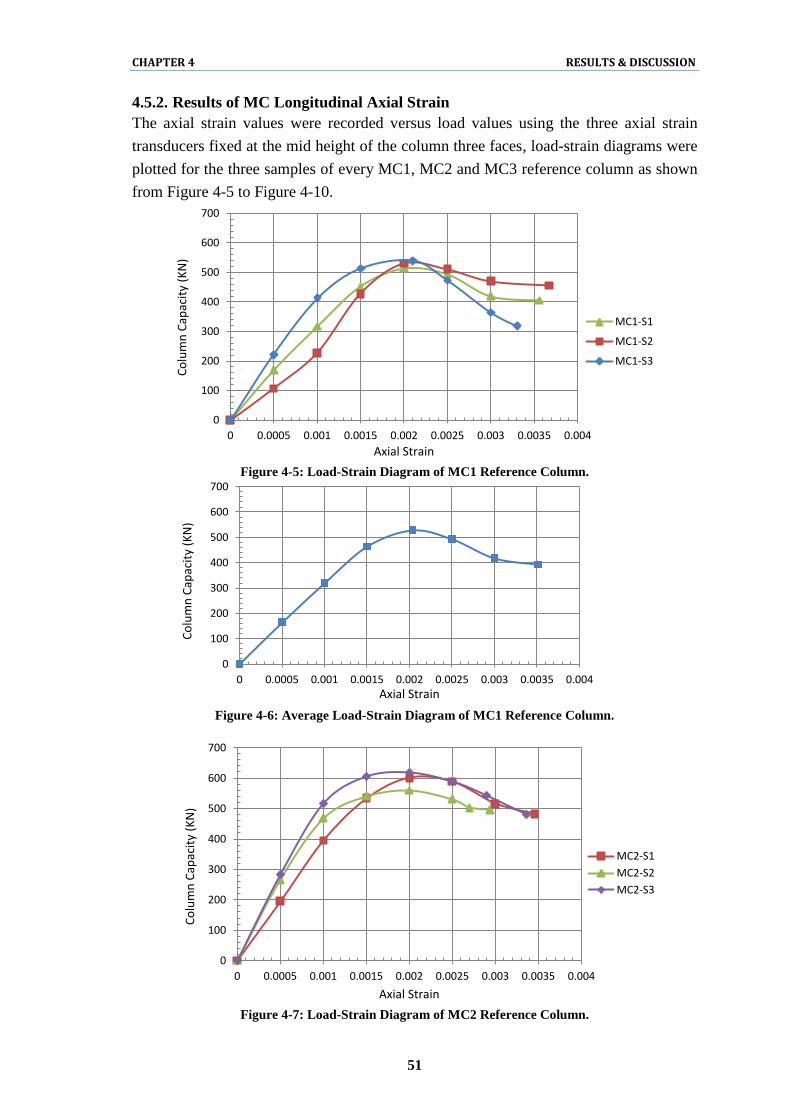
CHAPTER 4 RESULTS & DISCUSSION
51
Results of MC Longitudinal Axial Strain 4.5.2.
The axial strain values were recorded versus load values using the three axial strain
transducers fixed at the mid height of the column three faces, load-strain diagrams were
plotted for the three samples of every MC1, MC2 and MC3 reference column as shown
from Figure 4-5 to Figure 4-10.
Figure 4-5: Load-Strain Diagram of MC1 Reference Column.
Figure 4-6: Average Load-Strain Diagram of MC1 Reference Column.
Figure 4-7: Load-Strain Diagram of MC2 Reference Column.
0
100
200
300
400
500
600
700
0 0.0005 0.001 0.0015 0.002 0.0025 0.003 0.0035 0.004
Co
lum
n C
apac
ity
(KN
)
Axial Strain
MC1-S1
MC1-S2
MC1-S3
0
100
200
300
400
500
600
700
0 0.0005 0.001 0.0015 0.002 0.0025 0.003 0.0035 0.004
Co
lum
n C
apac
ity
(KN
)
Axial Strain
0
100
200
300
400
500
600
700
0 0.0005 0.001 0.0015 0.002 0.0025 0.003 0.0035 0.004
Co
lum
n C
apac
ity
(KN
)
Axial Strain
MC2-S1
MC2-S2
MC2-S3

CHAPTER 4 RESULTS & DISCUSSION
52
Figure 4-8: Average Load-Strain Diagram of MC2 Reference Column.
Figure 4-9: Load-Strain Diagram of MC3 Reference Column.
Figure 4-10: Average Load-Strain Diagram of MC3 Reference Column.
0
100
200
300
400
500
600
700
0 0.0005 0.001 0.0015 0.002 0.0025 0.003 0.0035 0.004
Co
lum
n C
apac
ity
(KN
)
Axial Strain
0
100
200
300
400
500
600
700
0 0.0005 0.001 0.0015 0.002 0.0025 0.003 0.0035 0.004
Co
lum
n C
apac
ity
(KN
)
Axial Strain
MC3-S1MC3-S2MC3-S3
0
100
200
300
400
500
600
700
0 0.0005 0.001 0.0015 0.002 0.0025 0.003 0.0035 0.004
Co
lum
n C
apac
ity
(KN
)
Axial Strain

CHAPTER 4 RESULTS & DISCUSSION
53
Figure 4-11 presents the obtained load strain diagrams of UC, MC1, MC2 and MC3
column specimens. The figure also shows that the load strain relations are nearly linear
up to one third the ultimate load carrying capacity, beyond which the curves became
nonlinear.
The UC, MC1, MC2 and MC3 reference columns reached their ultimate load carrying
capacities at axial strains of about 0.002, having almost equal axial strains at rupture
points of 0.0032, 0.0035, 0.0033 and 0.0031 respectively. This can be attributed to the
fact that they have similar steel reinforcement and were made of similar NSC mix.
Figure 4-11: Load-Strain Diagrams of UC, MC1, MC2 and MC3 Reference Columns.
4.6. G1 Jacketed Column Specimens
The G1 jacketed column specimens namely G1-25, G1-30 and G1-35 were consisted of
nine column cores strengthened using a jacket made of Fibrous UHPSCC and without
steel reinforcement cages in jacket. Shear connectors were used to mechanically bond
between column cores and its jacket. The results of G1 ultimate load carrying capacity
were studied in terms of jacket thickness, and compared with the corresponding UC and
MC reference columns. Longitudinal axial strains and failure patterns were also
obtained and compared with that of UC and MC reference columns.
Effect of Fibrous UHPSCC Unreinforced Jacketing on G1 Ultimate Load 4.6.1.
Carrying Capacity
Several jacket thicknesses namely 25, 30 and 35 mm gave an obvious increase in the
ultimate load carrying capacity. The overall composite cross sections of G1 jacketed
column specimens were made of two different concrete mixes; the column cores were
made of NSC mix and the outer jackets were made of Fibrous UHPSCC mix. Table 4-5
presents the average ultimate load carrying capacity of G1-25, G1-30 and G1-35.
0
100
200
300
400
500
600
700
0 0.0005 0.001 0.0015 0.002 0.0025 0.003 0.0035 0.004
Co
lum
n C
apac
ity
(KN
)
Axial Strain
UC
MC1
MC2
MC3

CHAPTER 4 RESULTS & DISCUSSION
54
Table 4-5: G1 Ultimate Load Carrying Capacity.
Notification Pu (KN) Overall Composite
Area (cm2)
Jacket Area
(cm2)
Column Core
Area (cm2)
G1-25-S1 1026.5
225 125
All Specimens
have column cores
area of 100 cm2
G1-25-S2 1064.2
G1-25-S3 1078.2
Average 1056.3
G1-30-S2 1226.1
256 156 G1-30-S2 1217.2
G1-30-S2 1250.3
Average 1231.2
G1-35-S3 1517.0
289 189 G1-35-S3 1535.9
G1-35-S3 1509.9
Average 1520.9
Figure 4-12 shows the effect of jacket thicknesses on G1 ultimate load carrying
capacity. The column cores were casted using NSC mix with unchanged cross section
of 100×100mm, thus the increase in cross sectional area was obtained by applying
several jacket thicknesses.
The ratios of jacket area of G1-30/G1-25 and G1-35/G1-25 equaled 1.25 and 1.51
respectively, while the corresponding ratios of ultimate load carrying capacity equaled
1.16 and 1.44 respectively. That has revealed the almost direct proportional relation
between jacket thickness and ultimate load carrying capacity of G1 jacketed column
specimens.
Figure 4-12: G1 Ultimate Load Carrying Capacity.
The results obtained were in agreement with that obtained by Abdelrahman [26] who
found that for regional strengthening, the ultimate load of strengthened columns was
less than the increase in the cross sectional area. But equal to the increase in the cross
sectional area if column entire length was jacketed.
In particular, jacket thickness is controlled by the required concrete covers in case of
traditional concrete jacketing. This often leads to thicknesses higher than 60 to100 mm
G1
-25
G1
-30
G1
-35
0
200
400
600
800
1000
1200
1400
1600
1800
225 256 289
Co
lum
n C
apac
ity
(KN
)
Column Composite Sectional Area (cm2)
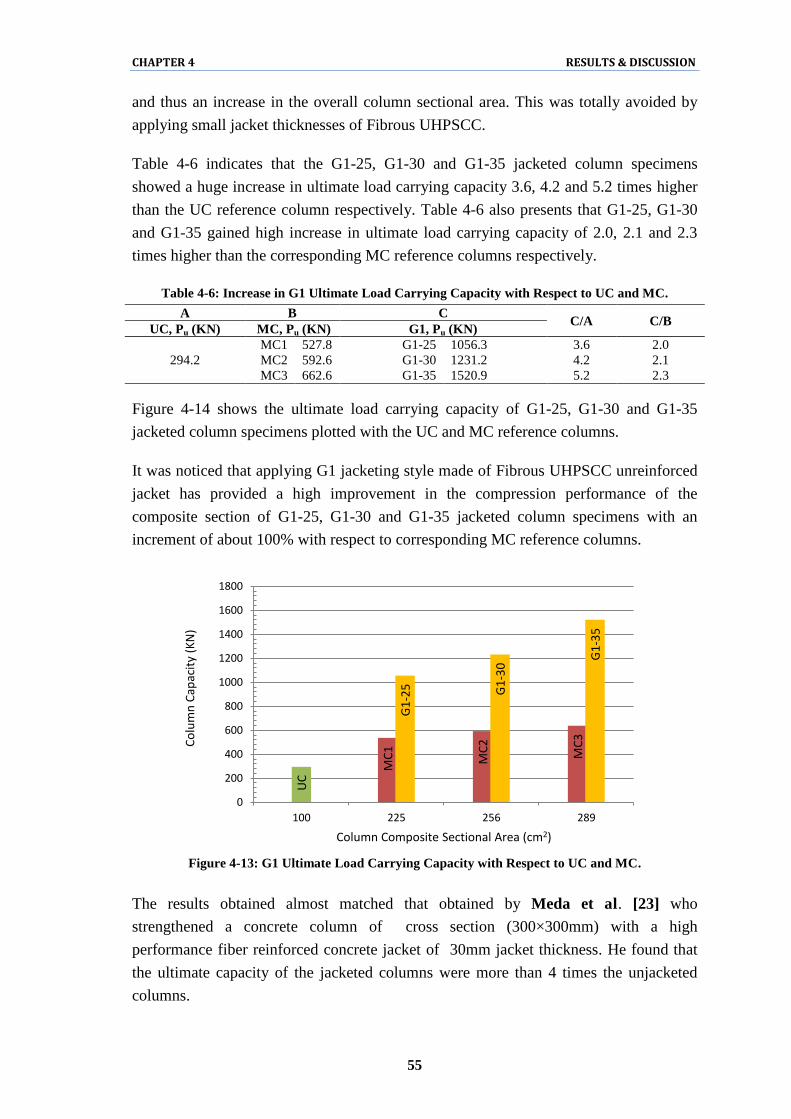
CHAPTER 4 RESULTS & DISCUSSION
55
and thus an increase in the overall column sectional area. This was totally avoided by
applying small jacket thicknesses of Fibrous UHPSCC.
Table 4-6 indicates that the G1-25, G1-30 and G1-35 jacketed column specimens
showed a huge increase in ultimate load carrying capacity 3.6, 4.2 and 5.2 times higher
than the UC reference column respectively. Table 4-6 also presents that G1-25, G1-30
and G1-35 gained high increase in ultimate load carrying capacity of 2.0, 2.1 and 2.3
times higher than the corresponding MC reference columns respectively.
Table 4-6: Increase in G1 Ultimate Load Carrying Capacity with Respect to UC and MC.
A B C C/A C/B
UC, Pu (KN) MC, Pu (KN) G1, Pu (KN)
294.2
MC1 527.8 G1-25 1056.3 3.6 2.0
MC2 592.6 G1-30 1231.2 4.2 2.1
MC3 662.6 G1-35 1520.9 5.2 2.3
Figure 4-14 shows the ultimate load carrying capacity of G1-25, G1-30 and G1-35
jacketed column specimens plotted with the UC and MC reference columns.
It was noticed that applying G1 jacketing style made of Fibrous UHPSCC unreinforced
jacket has provided a high improvement in the compression performance of the
composite section of G1-25, G1-30 and G1-35 jacketed column specimens with an
increment of about 100% with respect to corresponding MC reference columns.
Figure 4-13: G1 Ultimate Load Carrying Capacity with Respect to UC and MC.
The results obtained almost matched that obtained by Meda et al. [23] who
strengthened a concrete column of cross section (300×300mm) with a high
performance fiber reinforced concrete jacket of 30mm jacket thickness. He found that
the ultimate capacity of the jacketed columns were more than 4 times the unjacketed
columns.
MC
1
MC
2
MC
3
UC
G1
-25
G1
-30
G1
-35
0
200
400
600
800
1000
1200
1400
1600
1800
100 225 256 289
Co
lum
n C
apac
ity
(KN
)
Column Composite Sectional Area (cm2)

CHAPTER 4 RESULTS & DISCUSSION
56
Effect of Fibrous UHPSCC Unreinforced Jacketing on G1 Longitudinal 4.6.2.
Axial Strain
The axial strain values were recorded versus load values. The load-strain diagrams were
plotted for the three samples S1, S2 and S3 of the G1-25, G1-30 and G1-35 jacketed
column specimens. The average load-strain diagrams were also obtained and plotted as
shown from Figure 4-14 to Figure 4-19.
Figure 4-14: Load-Strain Diagram of G1-25 Jacketed Column Specimens.
Figure 4-15: Average Load-Strain Diagram of G1-25 Jacketed Column Specimens.
Figure 4-16: Load-Strain Diagram of G1-30 Jacketed Column Specimens.
0
200
400
600
800
1000
1200
1400
1600
0 0.001 0.002 0.003 0.004 0.005 0.006 0.007 0.008
Co
lum
n C
apac
ity
(KN
)
Axial Strain
G1-25-S1
G1-25-S2
G1-25-S3
0
200
400
600
800
1000
1200
1400
1600
0 0.001 0.002 0.003 0.004 0.005 0.006 0.007 0.008
Co
lum
n C
apac
ity
(KN
)
Axial Strain
0
200
400
600
800
1000
1200
1400
1600
0 0.001 0.002 0.003 0.004 0.005 0.006 0.007 0.008
Co
lum
n C
apac
ity
(KN
)
Axial Strain
G1-30-S1
G1-30-S2
G1-30-S3
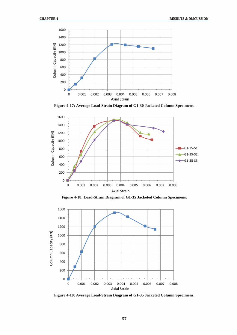
CHAPTER 4 RESULTS & DISCUSSION
57
Figure 4-17: Average Load-Strain Diagram of G1-30 Jacketed Column Specimens.
Figure 4-18: Load-Strain Diagram of G1-35 Jacketed Column Specimens.
Figure 4-19: Average Load-Strain Diagram of G1-35 Jacketed Column Specimens.
0
200
400
600
800
1000
1200
1400
1600
0 0.001 0.002 0.003 0.004 0.005 0.006 0.007 0.008
Co
lum
n C
apac
ity
(KN
)
Axial Strain
0
200
400
600
800
1000
1200
1400
1600
0 0.001 0.002 0.003 0.004 0.005 0.006 0.007 0.008
Co
lum
n C
apac
ity
(KN
)
Axial Strain
G1-35-S1
G1-35-S2
G1-35-S3
0
200
400
600
800
1000
1200
1400
1600
0 0.001 0.002 0.003 0.004 0.005 0.006 0.007 0.008
Co
lum
n C
apac
ity
(KN
)
Axial Strain
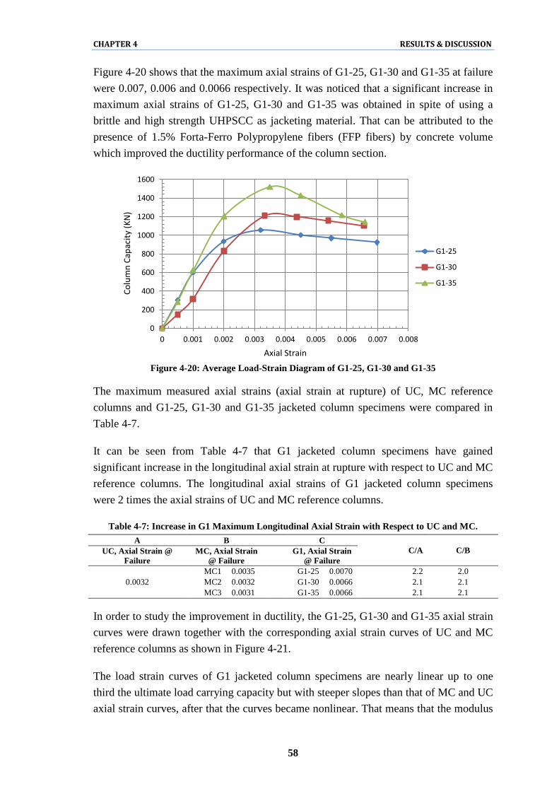
CHAPTER 4 RESULTS & DISCUSSION
58
Figure 4-20 shows that the maximum axial strains of G1-25, G1-30 and G1-35 at failure
were 0.007, 0.006 and 0.0066 respectively. It was noticed that a significant increase in
maximum axial strains of G1-25, G1-30 and G1-35 was obtained in spite of using a
brittle and high strength UHPSCC as jacketing material. That can be attributed to the
presence of 1.5% Forta-Ferro Polypropylene fibers (FFP fibers) by concrete volume
which improved the ductility performance of the column section.
Figure 4-20: Average Load-Strain Diagram of G1-25, G1-30 and G1-35
The maximum measured axial strains (axial strain at rupture) of UC, MC reference
columns and G1-25, G1-30 and G1-35 jacketed column specimens were compared in
Table 4-7.
It can be seen from Table 4-7 that G1 jacketed column specimens have gained
significant increase in the longitudinal axial strain at rupture with respect to UC and MC
reference columns. The longitudinal axial strains of G1 jacketed column specimens
were 2 times the axial strains of UC and MC reference columns.
Table 4-7: Increase in G1 Maximum Longitudinal Axial Strain with Respect to UC and MC.
A B C
C/A C/B UC, Axial Strain @
Failure
MC, Axial Strain
@ Failure
G1, Axial Strain
@ Failure
0.0032
MC1 0.0035 G1-25 0.0070 2.2 2.0
MC2 0.0032 G1-30 0.0066 2.1 2.1
MC3 0.0031 G1-35 0.0066 2.1 2.1
In order to study the improvement in ductility, the G1-25, G1-30 and G1-35 axial strain
curves were drawn together with the corresponding axial strain curves of UC and MC
reference columns as shown in Figure 4-21.
The load strain curves of G1 jacketed column specimens are nearly linear up to one
third the ultimate load carrying capacity but with steeper slopes than that of MC and UC
axial strain curves, after that the curves became nonlinear. That means that the modulus
0
200
400
600
800
1000
1200
1400
1600
0 0.001 0.002 0.003 0.004 0.005 0.006 0.007 0.008
Co
lum
n C
apac
ity
(KN
)
Axial Strain
G1-25
G1-30
G1-35
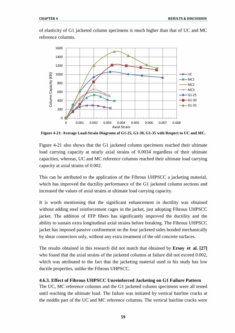
CHAPTER 4 RESULTS & DISCUSSION
59
of elasticity of G1 jacketed column specimens is much higher than that of UC and MC
reference columns.
Figure 4-21: Average Load-Strain Diagrams of G1-25, G1-30, G1-35 with Respect to UC and MC.
Figure 4-21 also shows that the G1 jacketed column specimens reached their ultimate
load carrying capacity at nearly axial strains of 0.0034 regardless of their ultimate
capacities, whereas, UC and MC reference columns reached their ultimate load carrying
capacity at axial strains of 0.002.
This can be attributed to the application of the Fibrous UHPSCC a jacketing material,
which has improved the ductility performance of the G1 jacketed column sections and
increased the values of axial strains at ultimate load carrying capacity.
It is worth mentioning that the significant enhancement in ductility was obtained
without adding steel reinforcement cages in the jacket, just adopting Fibrous UHPSCC
jacket. The addition of FFP fibers has significantly improved the ductility and the
ability to sustain extra longitudinal axial strains before breaking. The Fibrous UHPSCC
jacket has imposed passive confinement on the four jacketed sides bonded mechanically
by shear connectors only, without any extra treatment of the old concrete surfaces.
The results obtained in this research did not match that obtained by Ersoy et al. [27]
who found that the axial strains of the jacketed columns at failure did not exceed 0.002,
which was attributed to the fact that the jacketing material used in his study has low
ductile properties, unlike the Fibrous UHPSCC.
Effect of Fibrous UHPSCC Unreinforced Jacketing on G1 Failure Pattern 4.6.3.
The UC, MC reference columns and the G1 jacketed column specimens were all tested
until reaching the ultimate load. The failure was initiated by vertical hairline cracks at
the middle part of the UC and MC reference columns. The vertical hairline cracks were
0
200
400
600
800
1000
1200
1400
1600
0 0.001 0.002 0.003 0.004 0.005 0.006 0.007 0.008
Co
lum
n C
apac
ity
(KN
)
Axial Strain
UC
MC1
MC2
MC3
G1-25
G1-30
G1-35
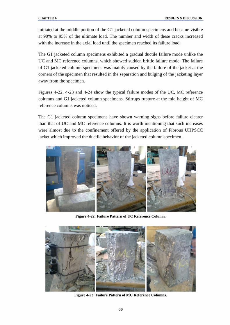
CHAPTER 4 RESULTS & DISCUSSION
60
initiated at the middle portion of the G1 jacketed column specimens and became visible
at 90% to 95% of the ultimate load. The number and width of these cracks increased
with the increase in the axial load until the specimen reached its failure load.
The G1 jacketed column specimens exhibited a gradual ductile failure mode unlike the
UC and MC reference columns, which showed sudden brittle failure mode. The failure
of G1 jacketed column specimens was mainly caused by the failure of the jacket at the
corners of the specimen that resulted in the separation and bulging of the jacketing layer
away from the specimen.
Figures 4-22, 4-23 and 4-24 show the typical failure modes of the UC, MC reference
columns and G1 jacketed column specimens. Stirrups rupture at the mid height of MC
reference columns was noticed.
The G1 jacketed column specimens have shown warning signs before failure clearer
than that of UC and MC reference columns. It is worth mentioning that such increases
were almost due to the confinement offered by the application of Fibrous UHPSCC
jacket which improved the ductile behavior of the jacketed column specimen.
`
Figure 4-22: Failure Pattern of UC Reference Column.
Figure 4-23: Failure Pattern of MC Reference Columns.

CHAPTER 4 RESULTS & DISCUSSION
61
Figure 4-24: Failure Pattern of G1 Jacketed Column Specimens.
4.7. G2 Jacketed Column Specimens
The G2 jacketed column specimens namely G2-25, G2-30 and G2-35 were consisted of
nine column cores strengthened using a jacket made of Non-Fibrous UHPSCC with
steel reinforcement cages in the jacket. Shear connectors were used to mechanically
bond between column cores and its jacket.
The results of G2 ultimate load carrying capacity were investigated in terms of jacket
thickness, and compared with the corresponding UC and MC reference columns. The
G2 longitudinal axial strains and failure patterns were also obtained and compared with
that of UC and MC reference columns.
Effect of Non-Fibrous UHPSCC Steel Reinforced Jacketing on G2 Ultimate 4.7.1.
Load Carrying Capacity
The several jacket thicknesses namely 25, 30 and 35 mm gave an obvious increase in
the ultimate load carrying capacity. The overall composite cross sections of G2 jacketed
column specimens were made of two different concrete mixes; column cores were made
of NSC mix and the outer jackets were made of Non-Fibrous UHPSCC mix. Table 4-8
presents the average ultimate load carrying capacity of G2-25, G2-30 and G2-35.
Table 4-8: G2 Ultimate Load Carrying Capacity.
Notification Pu (KN) Overall Composite
Area (cm2)
Jacket Area
(cm2)
Column Core
Area (cm2)
G2-25-S1 1015.6
225 125
All Specimens
have column
cores area of 100
cm2
G2-25-S1 1048.5
G2-25-S1 1023.8
Average 1029.3
G2-30-S1 1211.9
256 156 G2-30-S1 1225.9
G2-30-S1 1256.3
Average 1231.3
G2-35-S1 1438.1
289 189 G2-35-S1 1281.0
G2-35-S1 1489.3
Average 1402.8
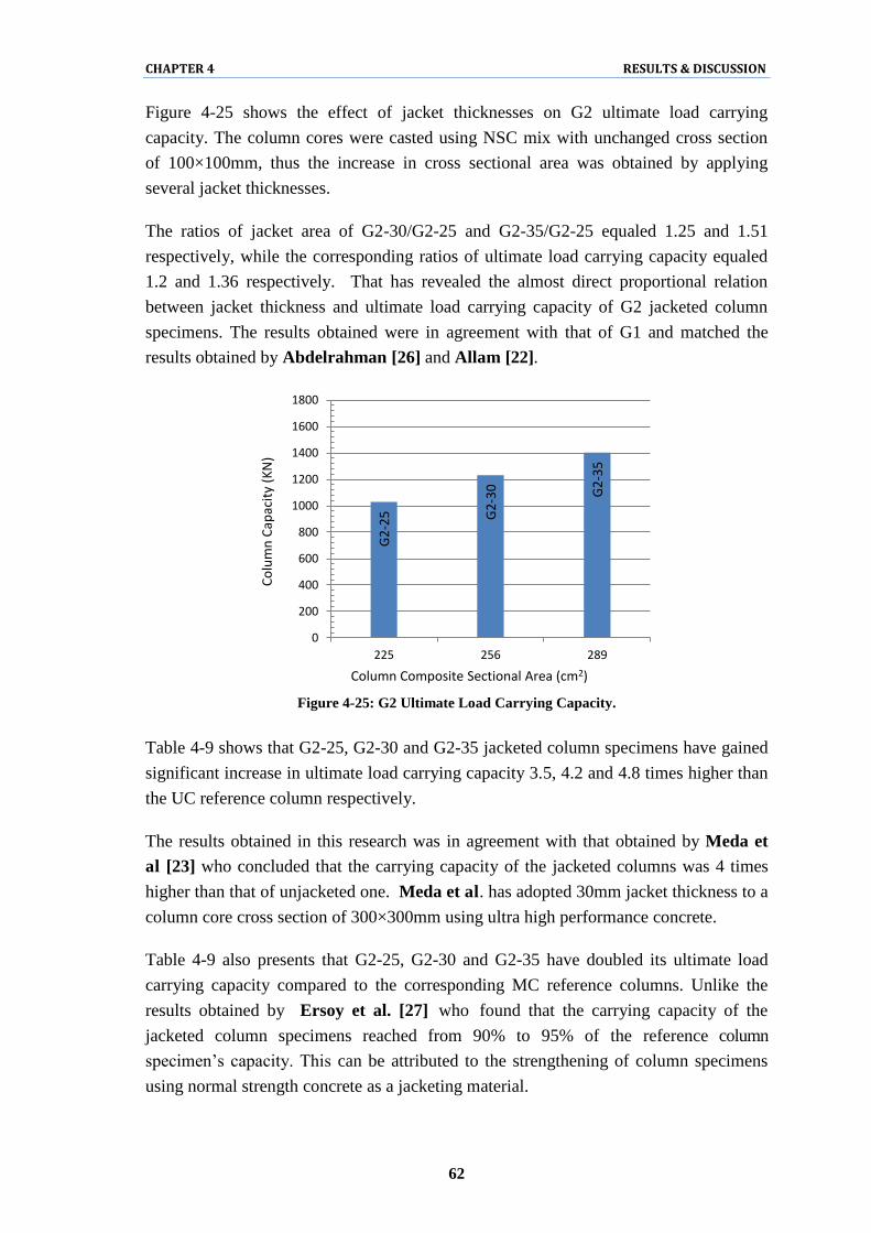
CHAPTER 4 RESULTS & DISCUSSION
62
Figure 4-25 shows the effect of jacket thicknesses on G2 ultimate load carrying
capacity. The column cores were casted using NSC mix with unchanged cross section
of 100×100mm, thus the increase in cross sectional area was obtained by applying
several jacket thicknesses.
The ratios of jacket area of G2-30/G2-25 and G2-35/G2-25 equaled 1.25 and 1.51
respectively, while the corresponding ratios of ultimate load carrying capacity equaled
1.2 and 1.36 respectively. That has revealed the almost direct proportional relation
between jacket thickness and ultimate load carrying capacity of G2 jacketed column
specimens. The results obtained were in agreement with that of G1 and matched the
results obtained by Abdelrahman [26] and Allam [22].
Figure 4-25: G2 Ultimate Load Carrying Capacity.
Table 4-9 shows that G2-25, G2-30 and G2-35 jacketed column specimens have gained
significant increase in ultimate load carrying capacity 3.5, 4.2 and 4.8 times higher than
the UC reference column respectively.
The results obtained in this research was in agreement with that obtained by Meda et
al [23] who concluded that the carrying capacity of the jacketed columns was 4 times
higher than that of unjacketed one. Meda et al. has adopted 30mm jacket thickness to a
column core cross section of 300×300mm using ultra high performance concrete.
Table 4-9 also presents that G2-25, G2-30 and G2-35 have doubled its ultimate load
carrying capacity compared to the corresponding MC reference columns. Unlike the
results obtained by Ersoy et al. [27] who found that the carrying capacity of the
jacketed column specimens reached from 90% to 95% of the reference column
specimen’s capacity. This can be attributed to the strengthening of column specimens
using normal strength concrete as a jacketing material.
G2
-25
G2
-30
G2
-35
0
200
400
600
800
1000
1200
1400
1600
1800
225 256 289
Co
lum
n C
apac
ity
(KN
)
Column Composite Sectional Area (cm2)
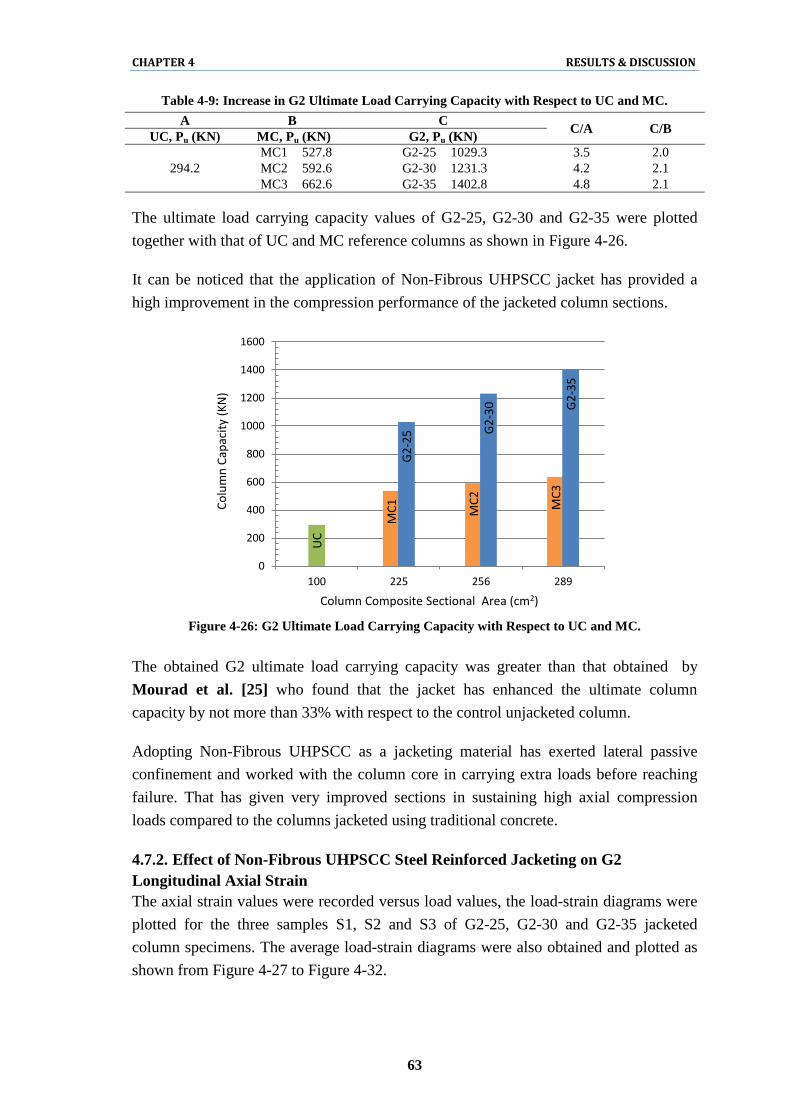
CHAPTER 4 RESULTS & DISCUSSION
63
Table 4-9: Increase in G2 Ultimate Load Carrying Capacity with Respect to UC and MC.
A B C C/A C/B
UC, Pu (KN) MC, Pu (KN) G2, Pu (KN)
294.2
MC1 527.8 G2-25 1029.3 3.5 2.0
MC2 592.6 G2-30 1231.3 4.2 2.1
MC3 662.6 G2-35 1402.8 4.8 2.1
The ultimate load carrying capacity values of G2-25, G2-30 and G2-35 were plotted
together with that of UC and MC reference columns as shown in Figure 4-26.
It can be noticed that the application of Non-Fibrous UHPSCC jacket has provided a
high improvement in the compression performance of the jacketed column sections.
Figure 4-26: G2 Ultimate Load Carrying Capacity with Respect to UC and MC.
The obtained G2 ultimate load carrying capacity was greater than that obtained by
Mourad et al. [25] who found that the jacket has enhanced the ultimate column
capacity by not more than 33% with respect to the control unjacketed column.
Adopting Non-Fibrous UHPSCC as a jacketing material has exerted lateral passive
confinement and worked with the column core in carrying extra loads before reaching
failure. That has given very improved sections in sustaining high axial compression
loads compared to the columns jacketed using traditional concrete.
Effect of Non-Fibrous UHPSCC Steel Reinforced Jacketing on G2 4.7.2.
Longitudinal Axial Strain
The axial strain values were recorded versus load values, the load-strain diagrams were
plotted for the three samples S1, S2 and S3 of G2-25, G2-30 and G2-35 jacketed
column specimens. The average load-strain diagrams were also obtained and plotted as
shown from Figure 4-27 to Figure 4-32.
MC
1
MC
2
MC
3
UC
G2
-25
G2
-30
G2
-35
0
200
400
600
800
1000
1200
1400
1600
100 225 256 289
Co
lum
n C
apac
ity
(KN
)
Column Composite Sectional Area (cm2)
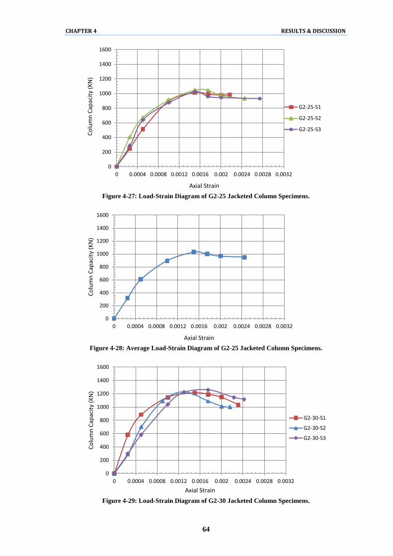
CHAPTER 4 RESULTS & DISCUSSION
64
Figure 4-27: Load-Strain Diagram of G2-25 Jacketed Column Specimens.
Figure 4-28: Average Load-Strain Diagram of G2-25 Jacketed Column Specimens.
Figure 4-29: Load-Strain Diagram of G2-30 Jacketed Column Specimens.
0
200
400
600
800
1000
1200
1400
1600
0 0.0004 0.0008 0.0012 0.0016 0.002 0.0024 0.0028 0.0032
Co
lum
n C
apac
ity
(KN
)
Axial Strain
G2-25-S1
G2-25-S2
G2-25-S3
0
200
400
600
800
1000
1200
1400
1600
0 0.0004 0.0008 0.0012 0.0016 0.002 0.0024 0.0028 0.0032
Co
lum
n C
apac
ity
(KN
)
Axial Strain
0
200
400
600
800
1000
1200
1400
1600
0 0.0004 0.0008 0.0012 0.0016 0.002 0.0024 0.0028 0.0032
Co
lum
n C
apac
ity
(KN
)
Axial Strain
G2-30-S1
G2-30-S2
G2-30-S3
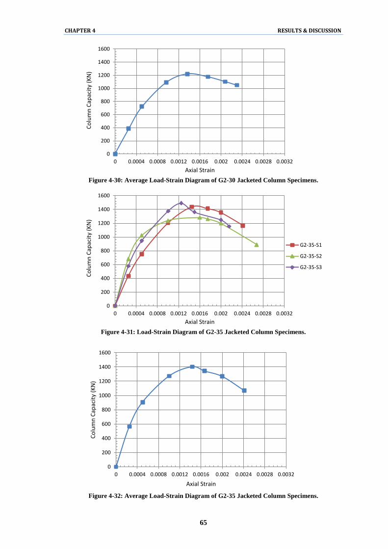
CHAPTER 4 RESULTS & DISCUSSION
65
Figure 4-30: Average Load-Strain Diagram of G2-30 Jacketed Column Specimens.
Figure 4-31: Load-Strain Diagram of G2-35 Jacketed Column Specimens.
Figure 4-32: Average Load-Strain Diagram of G2-35 Jacketed Column Specimens.
0
200
400
600
800
1000
1200
1400
1600
0 0.0004 0.0008 0.0012 0.0016 0.002 0.0024 0.0028 0.0032
Co
lum
n C
apac
ity
(KN
)
Axial Strain
0
200
400
600
800
1000
1200
1400
1600
0 0.0004 0.0008 0.0012 0.0016 0.002 0.0024 0.0028 0.0032
Co
lum
n C
apac
ity
(KN
)
Axial Strain
G2-35-S1
G2-35-S2
G2-35-S3
0
200
400
600
800
1000
1200
1400
1600
0 0.0004 0.0008 0.0012 0.0016 0.002 0.0024 0.0028 0.0032
Co
lum
n C
apac
ity
(KN
)
Axial Strain

CHAPTER 4 RESULTS & DISCUSSION
66
Figure 4-33 shows that the average longitudinal axial strains of G2-25, G2-30 and G2-
35 have decreased obviously to about 0.0024 at failure points, lower than 0.0032 the
average axial strain of UC and MC reference columns at failures. The brittle behavior of
G2 jacketed column specimens can be alleviated by increasing the confining steel
stirrups in the jacket that will improve transverse encasement and so on the ductility.
Figure 4-33: Average Load-Strain Diagram of G2-25, G2-30 and G2-35.
Table 4-10 also presents the decrease in the longitudinal axial strains of G2-25, G2-30
and G2-35 at the rupture points with respect to UC and MC reference columns. The
measured G2 longitudinal axial strain was reduced to 0.74 and 0.72 times the axial
strains of UC and MC reference columns respectively.
Table 4-10: Decrease in G2 Maximum Longitudinal Axial Strain with Respect to UC and MC.
A B C
C/A C/B UC, Axial Strain @
Failure
MC, Axial Strain
@ Failure
G2, Axial Strain
@ Failure
0.0032
MC1 0.0035 G2-25 0.0024 0.75 0.68
MC2 0.0032 G2-30 0.0023 0.71 0.71
MC3 0.0031 G2-35 0.0024 0.75 0.77
The G2-25, G2-30 and G2-35 axial strain curves were drawn together with UC and MC
curves as shown in Figure 4-34. The Figure 4-34 reveals that the load strain curves of
G2 jacketed column specimens are linear up to one third the ultimate load carrying
capacity but with steeper slopes than that of UC and MC axial strain curves, after that
the curves became nonlinear.
That means that the modulus of elasticity of G2 jacketed column specimens is much
higher than that of UC and MC reference columns. The G2 jacketed column specimens
reached their ultimate load carrying capacity at nearly axial strains of 0.0015 regardless
of their ultimate capacities, whereas UC and MC reference columns reached the
ultimate load carrying capacity at axial strains of about 0.002.
0
200
400
600
800
1000
1200
1400
1600
0 0.0004 0.0008 0.0012 0.0016 0.002 0.0024 0.0028 0.0032
Co
lum
n C
apac
ity
(KN
)
Axial Strain
G2-25
G2-30
G2-35
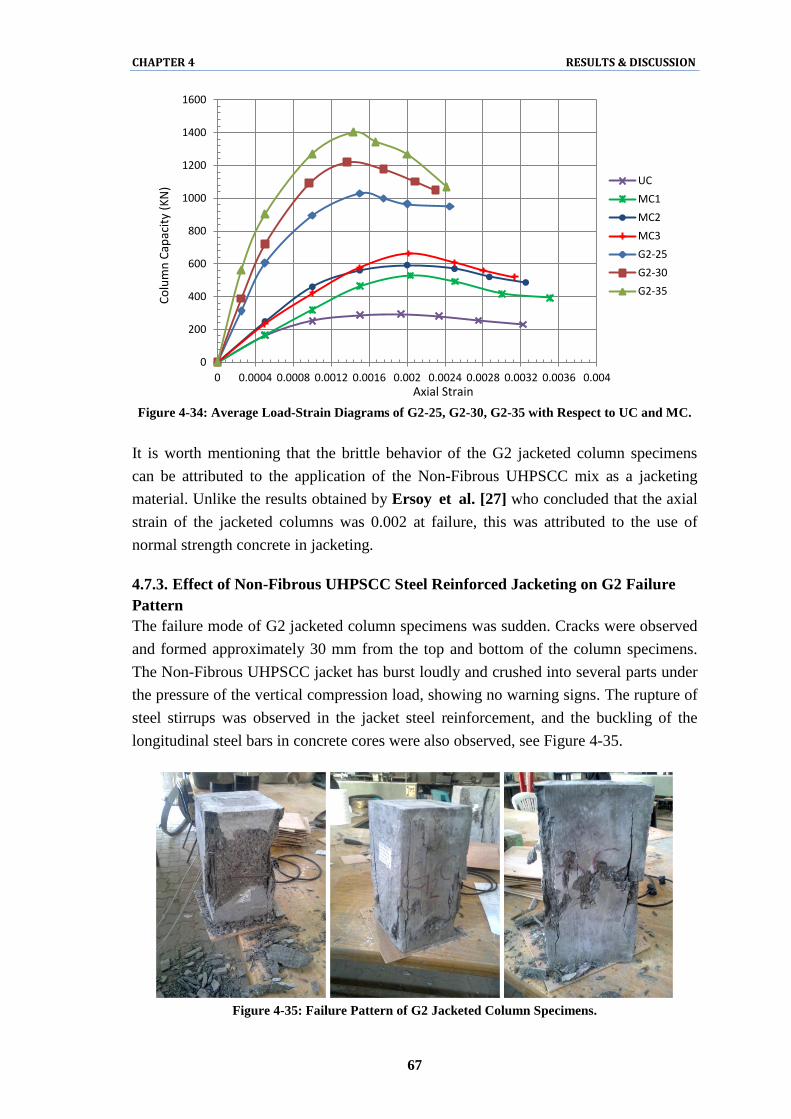
CHAPTER 4 RESULTS & DISCUSSION
67
Figure 4-34: Average Load-Strain Diagrams of G2-25, G2-30, G2-35 with Respect to UC and MC.
It is worth mentioning that the brittle behavior of the G2 jacketed column specimens
can be attributed to the application of the Non-Fibrous UHPSCC mix as a jacketing
material. Unlike the results obtained by Ersoy et al. [27] who concluded that the axial
strain of the jacketed columns was 0.002 at failure, this was attributed to the use of
normal strength concrete in jacketing.
Effect of Non-Fibrous UHPSCC Steel Reinforced Jacketing on G2 Failure 4.7.3.
Pattern
The failure mode of G2 jacketed column specimens was sudden. Cracks were observed
and formed approximately 30 mm from the top and bottom of the column specimens.
The Non-Fibrous UHPSCC jacket has burst loudly and crushed into several parts under
the pressure of the vertical compression load, showing no warning signs. The rupture of
steel stirrups was observed in the jacket steel reinforcement, and the buckling of the
longitudinal steel bars in concrete cores were also observed, see Figure 4-35.
Figure 4-35: Failure Pattern of G2 Jacketed Column Specimens.
0
200
400
600
800
1000
1200
1400
1600
0 0.0004 0.0008 0.0012 0.0016 0.002 0.0024 0.0028 0.0032 0.0036 0.004
Co
lum
n C
apac
ity
(KN
)
Axial Strain
UC
MC1
MC2
MC3
G2-25
G2-30
G2-35

CHAPTER 4 RESULTS & DISCUSSION
68
4.8. G3 Jacketed Column Specimens
The G3 jacketed column specimens namely G3-25, G3-30 and G3-35 were consisted of
nine column cores strengthened by jacketing using Fibrous UHPSCC steel reinforced
jacket. Shear connectors were used to mechanically bond between column cores and its
jackets.
The results of G3 ultimate load carrying capacity were investigated in terms of jacket
thickness, and compared with the corresponding UC and MC reference columns. The
G3 longitudinal axial strains and failure patterns were obtained and compared with that
of UC and MC reference columns.
Effect of Fibrous UHPSCC Steel Reinforced Jacketing on G3 Ultimate Load 4.8.1.
Carrying Capacity
The several jacket thicknesses namely 25, 30 and 35 mm gave an obvious increase in
the ultimate load carrying capacity. The overall composite cross sections of G3 jacketed
column specimens were composed of two different concrete mixes; the column cores
were made of NSC mix and the outer jackets were made of by Fibrous UHPSCC mix.
Table 4-11 presents the average ultimate load carrying capacity of G3-25, G3-30 and
G3-35.
Table 4-11: G3 Ultimate Load Carrying Capacity.
Notification Pu (KN) Overall Composite
Area (cm2)
Jacket Area
(cm2)
Column Core
Area (cm2)
G3C1-S1 1141.9
225 125
All Specimens
have column cores
area of 100 cm2
G3C1-S2 1125.8
G3C1-S3 1155.8
Average 1141.2
G3C2-S1 1372.8
256 156 G3C2-S2 1322.5
G3C2-S3 1301.5
Average 1332.2
G3C3-S1 1596.5
289 189 G3C3-S2 1575.8
G3C3-S3 1650.7
Average 1607.7
Figure 4-36 shows the effect of jacket thicknesses on G3 ultimate load carrying
capacity. The column cores were casted using NSC mix with unchanged cross section
of 100×100mm, thus the increase in cross sectional area was obtained by applying
several jacket thicknesses, almost similar to the obtained G1 and G2 results.
The ratios of jacket area of G3-30/G3-25 and G3-35/G3-25 equaled 1.25 and 1.51
respectively while the corresponding ratios of ultimate load carrying capacity equaled
1.17 and 1.4 respectively. That has confirmed the almost direct proportional relation
between jacket thickness and ultimate load carrying capacity of G3 jacketed column
specimens, same results obtained with respect to G1and G2 jacketed column specimens.
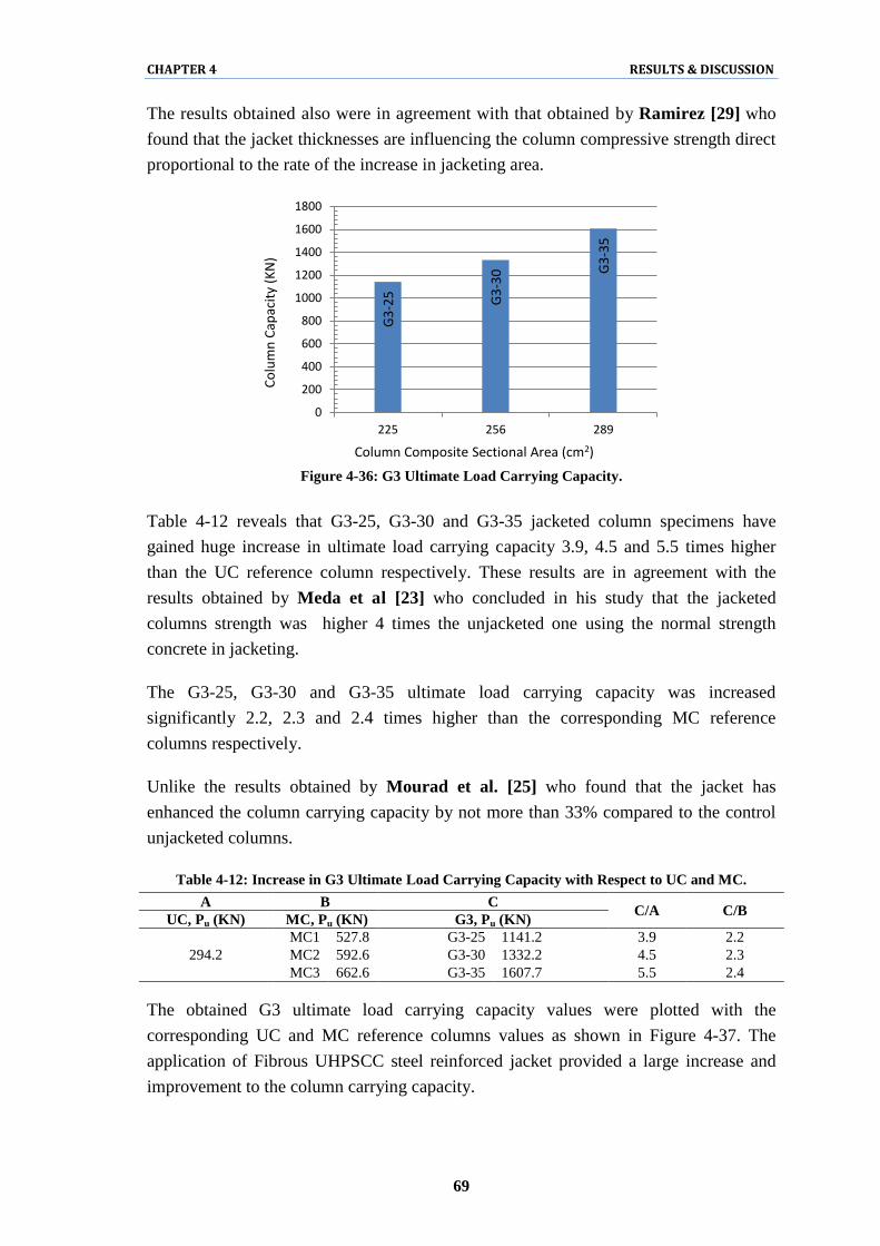
CHAPTER 4 RESULTS & DISCUSSION
69
The results obtained also were in agreement with that obtained by Ramirez [29] who
found that the jacket thicknesses are influencing the column compressive strength direct
proportional to the rate of the increase in jacketing area.
Figure 4-36: G3 Ultimate Load Carrying Capacity.
Table 4-12 reveals that G3-25, G3-30 and G3-35 jacketed column specimens have
gained huge increase in ultimate load carrying capacity 3.9, 4.5 and 5.5 times higher
than the UC reference column respectively. These results are in agreement with the
results obtained by Meda et al [23] who concluded in his study that the jacketed
columns strength was higher 4 times the unjacketed one using the normal strength
concrete in jacketing.
The G3-25, G3-30 and G3-35 ultimate load carrying capacity was increased
significantly 2.2, 2.3 and 2.4 times higher than the corresponding MC reference
columns respectively.
Unlike the results obtained by Mourad et al. [25] who found that the jacket has
enhanced the column carrying capacity by not more than 33% compared to the control
unjacketed columns.
Table 4-12: Increase in G3 Ultimate Load Carrying Capacity with Respect to UC and MC.
A B C C/A C/B
UC, Pu (KN) MC, Pu (KN) G3, Pu (KN)
294.2
MC1 527.8 G3-25 1141.2 3.9 2.2
MC2 592.6 G3-30 1332.2 4.5 2.3
MC3 662.6 G3-35 1607.7 5.5 2.4
The obtained G3 ultimate load carrying capacity values were plotted with the
corresponding UC and MC reference columns values as shown in Figure 4-37. The
application of Fibrous UHPSCC steel reinforced jacket provided a large increase and
improvement to the column carrying capacity.
G3
-25
G3
-30
G3
-35
0
200
400
600
800
1000
1200
1400
1600
1800
225 256 289
Co
lum
n C
apac
ity
(KN
)
Column Composite Sectional Area (cm2)
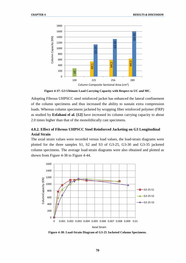
CHAPTER 4 RESULTS & DISCUSSION
70
Figure 4-37: G3 Ultimate Load Carrying Capacity with Respect to UC and MC.
Adopting Fibrous UHPSCC steel reinforced jacket has enhanced the lateral confinement
of the column specimens and thus increased the ability to sustain extra compression
loads. Whereas column specimens jacketed by wrapping fiber reinforced polymer (FRP)
as studied by Esfahani el al. [12] have increased its column carrying capacity to about
2.0 times higher than that of the monolithically cast specimens.
Effect of Fibrous UHPSCC Steel Reinforced Jacketing on G3 Longitudinal 4.8.2.
Axial Strain
The axial strain values were recorded versus load values, the load-strain diagrams were
plotted for the three samples S1, S2 and S3 of G3-25, G3-30 and G3-35 jacketed
column specimens. The average load-strain diagrams were also obtained and plotted as
shown from Figure 4-38 to Figure 4-44.
Figure 4-38: Load-Strain Diagram of G3-25 Jacketed Column Specimens.
MC
1
MC
2
MC
3
UC
G3
-25
G3
-30
G3
-35
0
200
400
600
800
1000
1200
1400
1600
1800
100 225 256 289
Co
lum
n C
apac
ity
(KN
)
Column Composite Sectional Area (cm2)
0
200
400
600
800
1000
1200
1400
1600
0 0.001 0.002 0.003 0.004 0.005 0.006 0.007 0.008 0.009 0.01
Co
lum
nC
apac
ity
(KN
)
Axial Strain
G3-25-S1
G3-25-S2
G3-25-S3
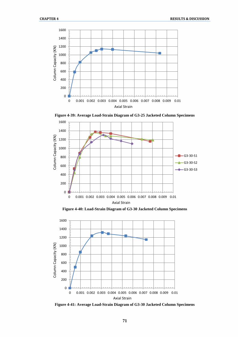
CHAPTER 4 RESULTS & DISCUSSION
71
Figure 4-39: Average Load-Strain Diagram of G3-25 Jacketed Column Specimens
Figure 4-40: Load-Strain Diagram of G3-30 Jacketed Column Specimens
Figure 4-41: Average Load-Strain Diagram of G3-30 Jacketed Column Specimens
0
200
400
600
800
1000
1200
1400
1600
0 0.001 0.002 0.003 0.004 0.005 0.006 0.007 0.008 0.009 0.01
Co
lum
n C
apac
ity
(KN
)
Axial Strain
0
200
400
600
800
1000
1200
1400
1600
0 0.001 0.002 0.003 0.004 0.005 0.006 0.007 0.008 0.009 0.01
Co
lum
n C
apac
ity
(KN
)
Axial Strain
G3-30-S1
G3-30-S2
G3-30-S3
0
200
400
600
800
1000
1200
1400
1600
0 0.001 0.002 0.003 0.004 0.005 0.006 0.007 0.008 0.009 0.01
Co
lum
n C
apac
ity
(KN
)
Axial Strain
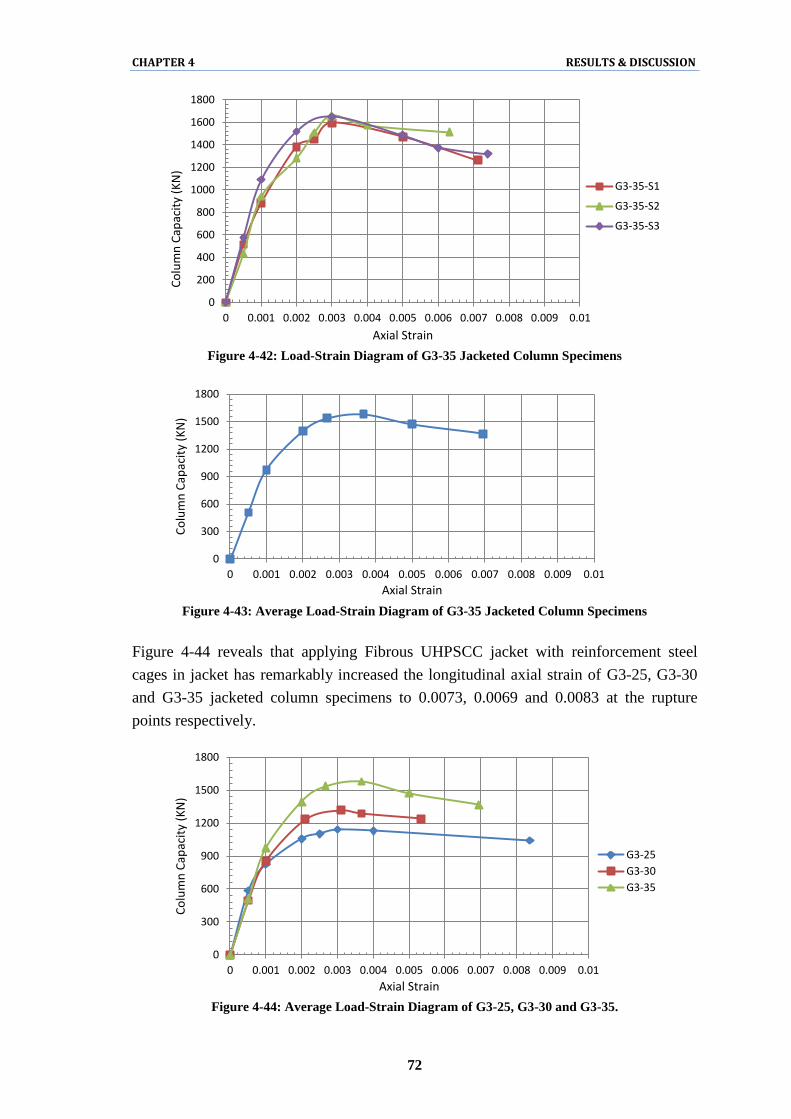
CHAPTER 4 RESULTS & DISCUSSION
72
Figure 4-42: Load-Strain Diagram of G3-35 Jacketed Column Specimens
Figure 4-43: Average Load-Strain Diagram of G3-35 Jacketed Column Specimens
Figure 4-44 reveals that applying Fibrous UHPSCC jacket with reinforcement steel
cages in jacket has remarkably increased the longitudinal axial strain of G3-25, G3-30
and G3-35 jacketed column specimens to 0.0073, 0.0069 and 0.0083 at the rupture
points respectively.
Figure 4-44: Average Load-Strain Diagram of G3-25, G3-30 and G3-35.
0
200
400
600
800
1000
1200
1400
1600
1800
0 0.001 0.002 0.003 0.004 0.005 0.006 0.007 0.008 0.009 0.01
Co
lum
n C
apac
ity
(KN
)
Axial Strain
G3-35-S1
G3-35-S2
G3-35-S3
0
300
600
900
1200
1500
1800
0 0.001 0.002 0.003 0.004 0.005 0.006 0.007 0.008 0.009 0.01
Co
lum
n C
apac
ity
(KN
)
Axial Strain
0
300
600
900
1200
1500
1800
0 0.001 0.002 0.003 0.004 0.005 0.006 0.007 0.008 0.009 0.01
Co
lum
n C
apac
ity
(KN
)
Axial Strain
G3-25
G3-30
G3-35
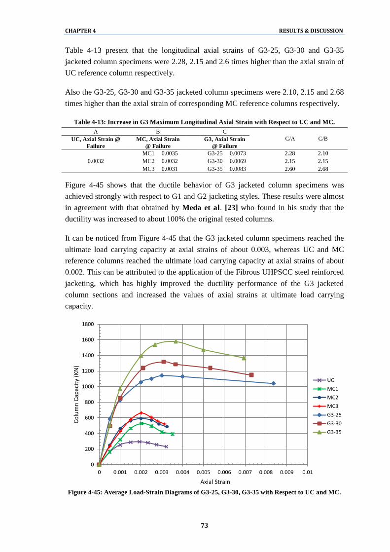
CHAPTER 4 RESULTS & DISCUSSION
73
Table 4-13 present that the longitudinal axial strains of G3-25, G3-30 and G3-35
jacketed column specimens were 2.28, 2.15 and 2.6 times higher than the axial strain of
UC reference column respectively.
Also the G3-25, G3-30 and G3-35 jacketed column specimens were 2.10, 2.15 and 2.68
times higher than the axial strain of corresponding MC reference columns respectively.
Table 4-13: Increase in G3 Maximum Longitudinal Axial Strain with Respect to UC and MC.
A B C
C/A C/B UC, Axial Strain @
Failure
MC, Axial Strain
@ Failure
G3, Axial Strain
@ Failure
0.0032
MC1 0.0035 G3-25 0.0073 2.28 2.10
MC2 0.0032 G3-30 0.0069 2.15 2.15
MC3 0.0031 G3-35 0.0083 2.60 2.68
Figure 4-45 shows that the ductile behavior of G3 jacketed column specimens was
achieved strongly with respect to G1 and G2 jacketing styles. These results were almost
in agreement with that obtained by Meda et al. [23] who found in his study that the
ductility was increased to about 100% the original tested columns.
It can be noticed from Figure 4-45 that the G3 jacketed column specimens reached the
ultimate load carrying capacity at axial strains of about 0.003, whereas UC and MC
reference columns reached the ultimate load carrying capacity at axial strains of about
0.002. This can be attributed to the application of the Fibrous UHPSCC steel reinforced
jacketing, which has highly improved the ductility performance of the G3 jacketed
column sections and increased the values of axial strains at ultimate load carrying
capacity.
Figure 4-45: Average Load-Strain Diagrams of G3-25, G3-30, G3-35 with Respect to UC and MC.
0
200
400
600
800
1000
1200
1400
1600
1800
0 0.001 0.002 0.003 0.004 0.005 0.006 0.007 0.008 0.009 0.01
Co
lum
n C
apac
ity
(KN
)
Axial Strain
UC
MC1
MC2
MC3
G3-25
G3-30
G3-35
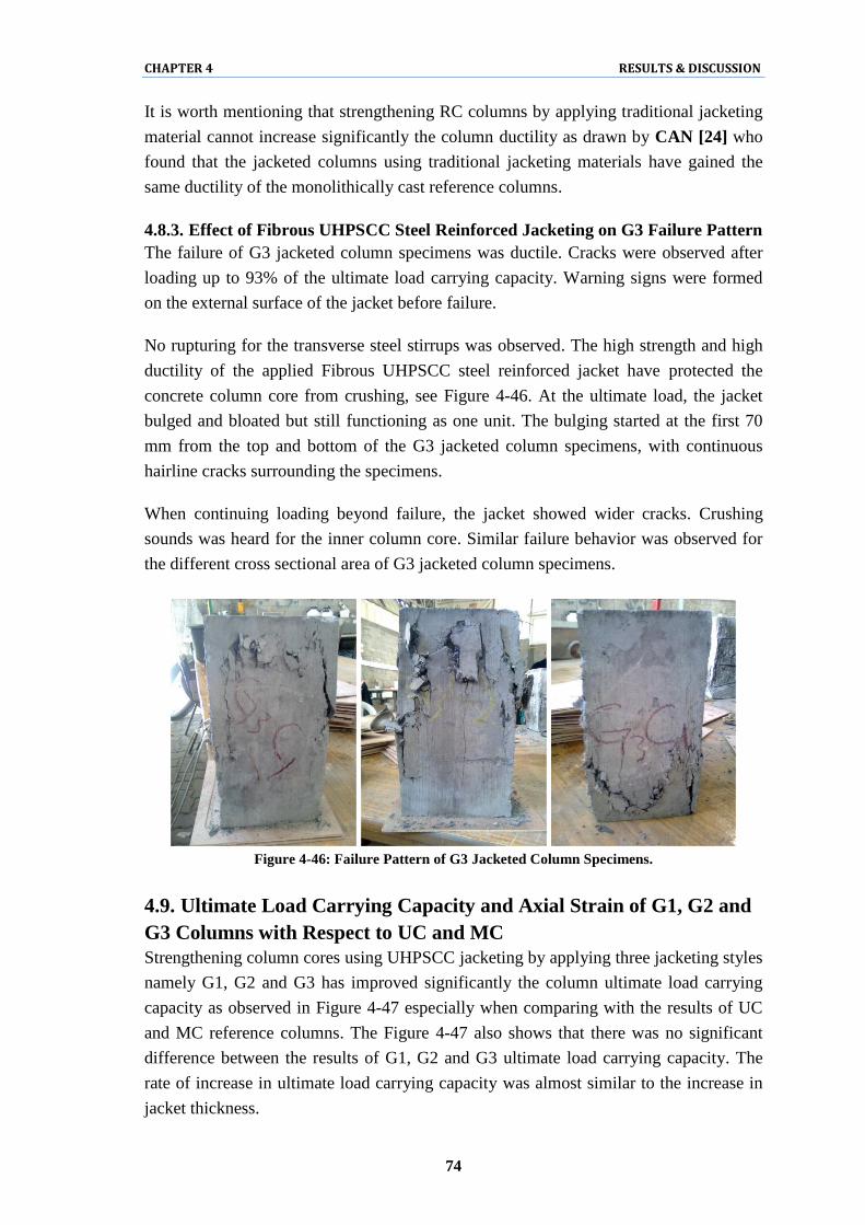
CHAPTER 4 RESULTS & DISCUSSION
74
It is worth mentioning that strengthening RC columns by applying traditional jacketing
material cannot increase significantly the column ductility as drawn by CAN [24] who
found that the jacketed columns using traditional jacketing materials have gained the
same ductility of the monolithically cast reference columns.
Effect of Fibrous UHPSCC Steel Reinforced Jacketing on G3 Failure Pattern 4.8.3.
The failure of G3 jacketed column specimens was ductile. Cracks were observed after
loading up to 93% of the ultimate load carrying capacity. Warning signs were formed
on the external surface of the jacket before failure.
No rupturing for the transverse steel stirrups was observed. The high strength and high
ductility of the applied Fibrous UHPSCC steel reinforced jacket have protected the
concrete column core from crushing, see Figure 4-46. At the ultimate load, the jacket
bulged and bloated but still functioning as one unit. The bulging started at the first 70
mm from the top and bottom of the G3 jacketed column specimens, with continuous
hairline cracks surrounding the specimens.
When continuing loading beyond failure, the jacket showed wider cracks. Crushing
sounds was heard for the inner column core. Similar failure behavior was observed for
the different cross sectional area of G3 jacketed column specimens.
Figure 4-46: Failure Pattern of G3 Jacketed Column Specimens.
4.9. Ultimate Load Carrying Capacity and Axial Strain of G1, G2 and
G3 Columns with Respect to UC and MC
Strengthening column cores using UHPSCC jacketing by applying three jacketing styles
namely G1, G2 and G3 has improved significantly the column ultimate load carrying
capacity as observed in Figure 4-47 especially when comparing with the results of UC
and MC reference columns. The Figure 4-47 also shows that there was no significant
difference between the results of G1, G2 and G3 ultimate load carrying capacity. The
rate of increase in ultimate load carrying capacity was almost similar to the increase in
jacket thickness.

CHAPTER 4 RESULTS & DISCUSSION
75
Figure 4-47: G1, G2 and G3 Ultimate Load Carrying Capacity with Respect to UC and MC.
The ultimate load carrying capacity of G1, G2 and G3 increased to about 4 and 2 times
higher than the corresponding UC and MC reference columns respectively.
Also, there was no significant difference between ultimate load carrying capacity of G2
and G1 jacketed column specimens. In spite of the absence of steel reinforcement cages
in G1 jacketed column specimens; Fibrous UHPSCC improved the characteristics of the
jacket. The Fibrous UHPSCC has exerted passive confinement on the column core to
sustain load several times higher than its ultimate load capacity.
It is worth mentioning that in spite of the absence of any surface treatment such as
scrapping, roughening or chemicals painting; the mechanical bonding using shear
connectors has shown good interface adherence between the old concrete and the
applied jacket.
Moreover, G1 jacketing style has proved a good bonding, even without adding
reinforcement steel cages in the jacket and that can be attributed to the application of L-
shape shear connectors along the four faces of the column cores.
It can also be mentioned that the addition of Forta-Ferro Polypropylene (FFP) fibers of
about 1.5% by the volume of UHPSCC mix has significantly improved the ductile
behavior and the compression performance of the jacketed column sections of G1 and
G3 as shown from Figure 4-48 to Figure 4-50. Noting that the failure modes of G1 and
G3 jacketed column specimens were improved giving warning signs before reaching
failure.
UC
MC
1
MC
2
MC
3
G1
-25
G1
-30
G1
-35
G2
-25
G2
-30
G2
-35
G3
-25
G3
-30
G3
-35
0
200
400
600
800
1000
1200
1400
1600
1800
100 225 256 289
Co
lum
n C
apac
ity
(KN
)
Column Composite Sectional Area (cm2)
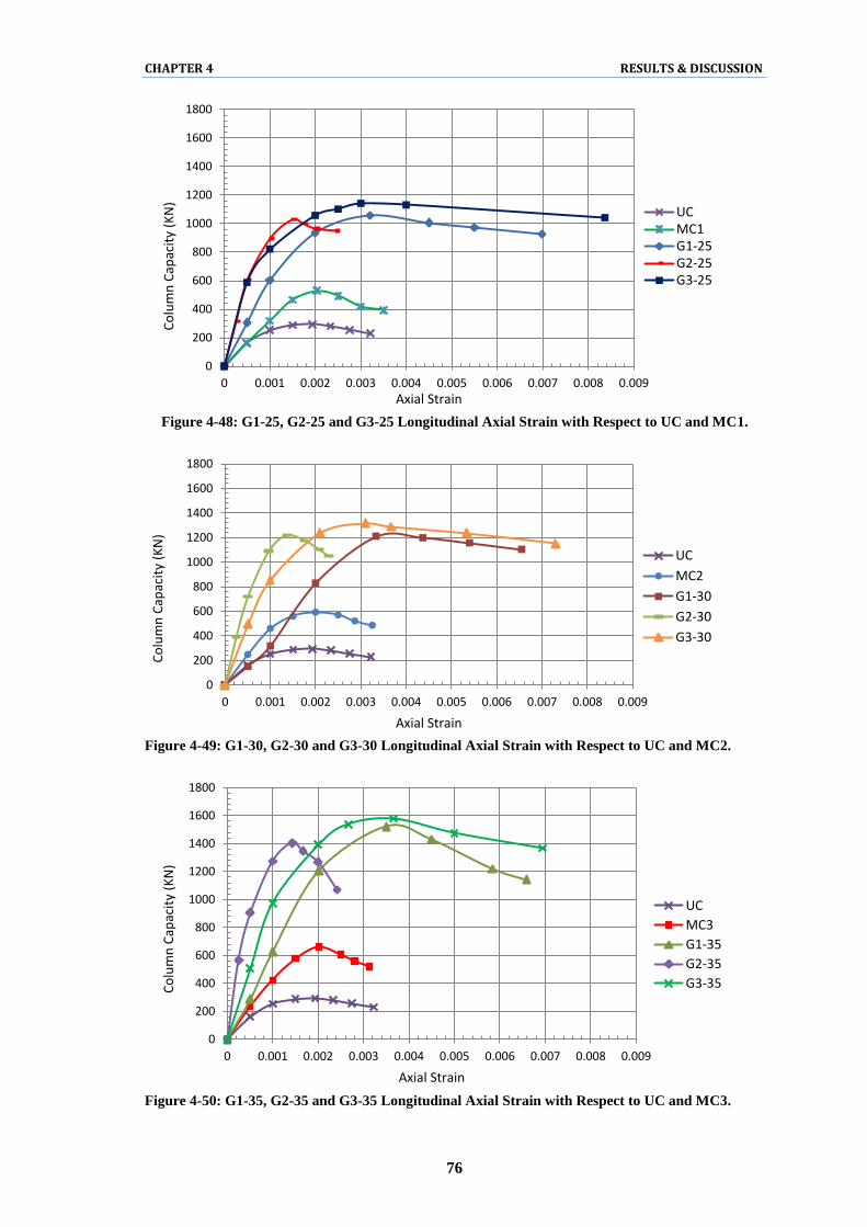
CHAPTER 4 RESULTS & DISCUSSION
76
Figure 4-48: G1-25, G2-25 and G3-25 Longitudinal Axial Strain with Respect to UC and MC1.
Figure 4-49: G1-30, G2-30 and G3-30 Longitudinal Axial Strain with Respect to UC and MC2.
Figure 4-50: G1-35, G2-35 and G3-35 Longitudinal Axial Strain with Respect to UC and MC3.
0
200
400
600
800
1000
1200
1400
1600
1800
0 0.001 0.002 0.003 0.004 0.005 0.006 0.007 0.008 0.009
Co
lum
n C
apac
ity
(KN
)
Axial Strain
UCMC1G1-25G2-25G3-25
0
200
400
600
800
1000
1200
1400
1600
1800
0 0.001 0.002 0.003 0.004 0.005 0.006 0.007 0.008 0.009
Co
lum
n C
apac
ity
(KN
)
Axial Strain
UC
MC2
G1-30
G2-30
G3-30
0
200
400
600
800
1000
1200
1400
1600
1800
0 0.001 0.002 0.003 0.004 0.005 0.006 0.007 0.008 0.009
Co
lum
n C
apac
ity
(KN
)
Axial Strain
UC
MC3
G1-35
G2-35
G3-35
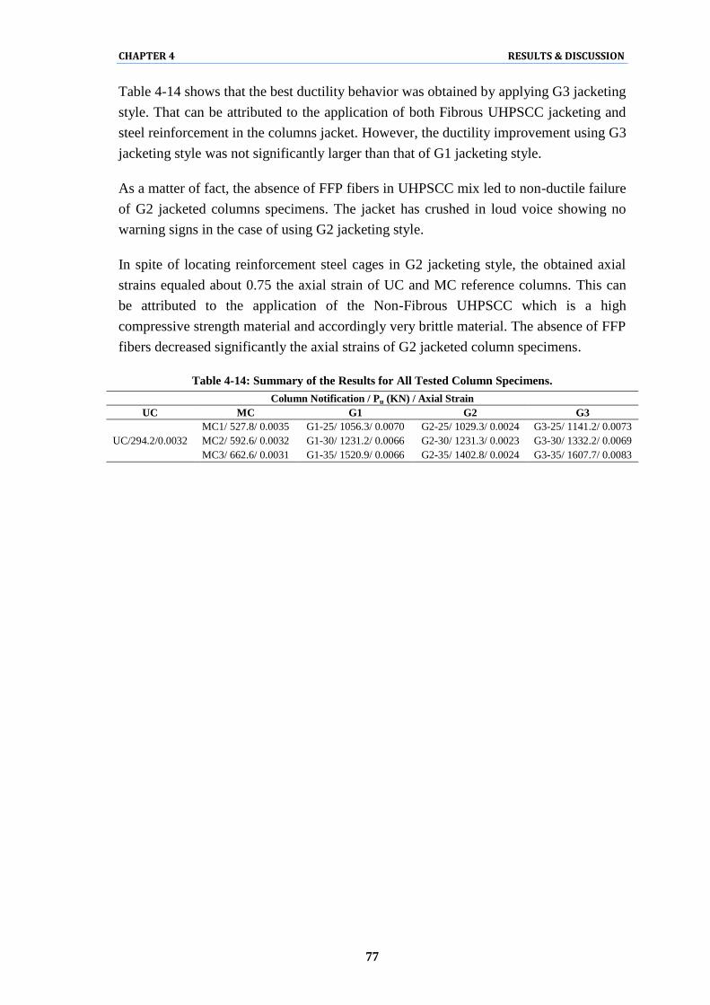
CHAPTER 4 RESULTS & DISCUSSION
77
Table 4-14 shows that the best ductility behavior was obtained by applying G3 jacketing
style. That can be attributed to the application of both Fibrous UHPSCC jacketing and
steel reinforcement in the columns jacket. However, the ductility improvement using G3
jacketing style was not significantly larger than that of G1 jacketing style.
As a matter of fact, the absence of FFP fibers in UHPSCC mix led to non-ductile failure
of G2 jacketed columns specimens. The jacket has crushed in loud voice showing no
warning signs in the case of using G2 jacketing style.
In spite of locating reinforcement steel cages in G2 jacketing style, the obtained axial
strains equaled about 0.75 the axial strain of UC and MC reference columns. This can
be attributed to the application of the Non-Fibrous UHPSCC which is a high
compressive strength material and accordingly very brittle material. The absence of FFP
fibers decreased significantly the axial strains of G2 jacketed column specimens.
Table 4-14: Summary of the Results for All Tested Column Specimens.
Column Notification / Pu (KN) / Axial Strain
UC MC G1 G2 G3
UC/294.2/0.0032
MC1/ 527.8/ 0.0035 G1-25/ 1056.3/ 0.0070 G2-25/ 1029.3/ 0.0024 G3-25/ 1141.2/ 0.0073
MC2/ 592.6/ 0.0032 G1-30/ 1231.2/ 0.0066 G2-30/ 1231.3/ 0.0023 G3-30/ 1332.2/ 0.0069
MC3/ 662.6/ 0.0031 G1-35/ 1520.9/ 0.0066 G2-35/ 1402.8/ 0.0024 G3-35/ 1607.7/ 0.0083
CHAPTER 5CONCLUSIONS & RECOMMENDATIONS
CHAPTER 5 CONCLUSIONS & RECOMMENDATIONS
79
5.1. Introduction
This research investigated the ultimate load carrying capacity and the longitudinal axial
strain of square RC columns strengthened by applying three jacketing styles. All
fabricated column specimens were subjected to monotonically low rate of uniaxial
compression loading.
Three jacketing styles namely G1, G2 and G3 have been studied experimentally to
investigate the effectiveness of every jacketing style. Fibrous UHPSCC was applied as a
jacketing material with G1 and G3 jacketing styles, whereas Non-Fibrous UHPSCC
jacket was applied with G2 jacketing style.
G1, G2 and G3 jacketing styles consisted of 27 column specimens in total (9 column
specimens for each jacketing style), while the UC and MC reference columns consisted
of 12 column specimens. All fabricated column specimens were tested at IUG Soil and
Materials laboratory. The results obtained in this research were summarized in the
following conclusion:
5.2. Conclusion
The following concluding remarks were drawn from the obtained experimental
observations:
Strengthening RC columns by applying Fibrous UHPSCC as a jacketing material
was effective and has reduced the total strengthened column sections.
The Fibrous UHPSCC can flow easily into narrow form sections without
segregation or honeycombing problems, even in cases of steel congested sections.
The relationships between the applied load and axial strain of the tested column
specimens were typical, a linear behavior up to one third of the ultimate load
carrying capacity followed by a non-linear behavior until failure.
The slope of the first part of the plotted load strain curves of UC and MC reference
columns was almost the same, while being steeper slope when strengthened with
Fibrous and Non Fibrous UHPSCC. Steeper slope means that the modulus of
elasticity of strengthened columns has increased.
Strengthening by applying Fibrous UHPSCC jacket increased significantly the
ultimate load carrying capacity and the longitudinal axial strain with respect to UC
and MC reference columns.
The ultimate load carrying capacity of G1, G2 and G3 jacketed column specimens
increased linearly having the same rate of the increase in jacketing area.

CHAPTER 5 CONCLUSIONS & RECOMMENDATIONS
80
Applying several jacket thicknesses of 25, 30 and 35 mm with G1, G2 and G3
jacketing styles improved considerably the ultimate load carrying capacity in
almost a similar rate with respect to the rate of increase in jacketing area.
The G1-25, G1-30 and G1-35 gained significant increase in the ultimate load
carrying capacity higher 3.6, 4.2 and 5.2 times than the results of UC reference
column respectively, and higher about 2.0 times than the corresponding MC
reference columns.
The longitudinal axial strain of G1-25, G1-30 and G1-35 increased significantly to
about 2.1 times the axial strain of UC and MC reference columns.
The G2-25, G2-30 and G2-35 also gained significant increase in ultimate load
carrying capacity higher 3.5, 4.2, and 4.8 times than the UC reference column
respectively, and higher about 2.0 times than the MC reference columns.
The longitudinal axial strain of G2-25, G2-30 and G2-35 was reduced to about
0.74 times the axial strain of UC reference column, and about 0.73 times the MC
reference columns.
The G3-25, G3-30 and G3-35 also gained considerable increase in ultimate load
carrying capacity higher 3.9, 4.5, and 5.5 times than the UC reference column, and
higher about 2.3 times than the MC reference columns respectively.
The longitudinal axial strain of G3-25, G3-30 and G3-35 was increased to about
2.3 times the axial strain of UC and MC reference columns.
G2-25, G2-30 and G2-35 reached their maximum longitudinal axial strains of
about 0.0024 at failure, the severe reduction in axial strain was attributed to the
brittle behavior of the used jacketing material which is the Non-Fibrous UHPSCC.
Adding Forta-Ferro Polypropylene fibers (FFP) of 1.5 % by the volume of
UHPSCC mix has improved the properties by increasing the maximum
longitudinal axial strain of G1 and G3 jacketed column specimens to about 0.0067
and 0.0075 respectively.
The G3 jacketing style have significantly increased the ultimate load carrying
capacity and ductility of the jacketed column cores because of the application of
both Fibrous and steel reinforced UHPSCC jacket, however the increase was not
so significant with respect to the increase obtained by G1 jacketing style.
The failure modes of G1 and G3 jacketed column specimens were ductile giving
noticeable warning signs under loading before crushing and spalling out.
CHAPTER 5 CONCLUSIONS & RECOMMENDATIONS
81
The failure modes of UC and MC reference columns were ductile giving
longitudinal axial strains of 0.0032 and 0.0033 respectively that was attributed to
the application of a normal strength concrete (NSC) in casting the reference
columns.
The failure mode of G2 jacketed column specimens was brittle. That was observed
by crushing loudly giving no previous warning signals.
5.3. Recommendations
The following findings and suggestions can be pointed out as recommendations for
future studies:
Findings 5.3.1.
As result of this study it is recommended to strengthen the four sides of square RC
columns using the Fibrous UHPSCC as a jacketing material, as it is a high compressive
strength material and reinforced by FFP fibers which enhanced the ductility and reduced
the jacketing thickness.
The self-compaction behavior of the Fibrous UHPSCC is very effective in casting the
RC column jackets easily without manual compaction. The importance of using self-
compacting concrete is the fact that the real life jacketing thickness is usually small and
steel congested which often causes segregation and honeycombing problems.
Suggestions 5.3.2.
The following point can be drawn for future studies:
Different bonding techniques should be investigated in further studies and
compared to what is obtained in this study.
Applying a localized strengthening jacket on different lengths of the strengthened
columns not only for the entire column length.
Studying the strengthening of columns after being loaded to actually represent the
columns condition in real life.
Studying the effect of the cycles of loading before strengthening the columns, as
well as the effect of eccentricity on jacketed columns.
Studying the behavior of slender strengthened columns under loading with
different slenderness ratios, and compare results with results of this research.
Studying the effect of the transverse steel stirrups.
Studying the efficiency of jacketing three or two sides of the RC columns instead
of jacketing its four sides.

REFERENCES
REFERENCES
83
[1] Fukuyama K., Higashibata Y., and Miyauchi Y., 2000 ―Studies on repair and
strengthening methods of damaged reinforced concrete columns,‖ Cement and
Concrete Composites 22 (2000) 81-88.
[2] Perry V. H., and Zakariasen D. 2004,‖First Use of Ultra-High Performance
Concrete for an Innovative Train Station Canopy‖, Portland cement association.
[3] Mucteba U., and Sumer M., 2011 ―Performance of self-compacting concrete
containing different mineral admixture‖, Construction and Building Materials,
vol 25, pp. 4112-4120.
[4] Forta Company, http://www.forta-ferro.com., Access date:15/12/2014.
[5] Shihada S., and Jerjawy M., 2011 ―Assessment and Strengthening of a Sixteen
Storey RC Building Damaged By Air Attack‖, The Islamic University Journal,
Vol.19, No.2, pp 37-56 , 2011, ISSN 1726-6807.
[6] Bsisu KD., 2002 ―Retrofitting of Square Reinforced Concrete Columns
Subjected to Concentric Axial Loading with Steel Jackets,‖ Paper in the
Palestinian third consultant engineering conference.
[7] Frangou M., Pilakoutas K., and Dritsos S., 1995 ―Structural repair/
strengthening of RC columns,‖ Construction and Building Materials, Vol. 9,
No. 5, pp. 259-266, 1995.
[8] Sheikh S. A., 2002 ―Performance of concrete structures retrofitted with fibre
reinforced polymers,‖ Engineering Structures 24 (2002) 869-879.
[9] Campione G., 2010 ―Strength and ductility of R.C. columns strengthened with
steel angles and battens‖ Dipartimento di Ingegneria Civile, Ambientale e
Aerospaziale e Geotecnica, Università degli Studi di Palermo, Viale delle
Scienze, 90128 Palermo, Italy.
[10] Katsumata H., Kimura K., and Murahashi H., 2001 ―Experience of FRP
Strengthening for Japanese Historical Structures,‖ Proceedings International
Conference FRP Composites in Civil Engineering, V. 2, Elsevier Science, New
York, pp. 1001-1008, 2001.
[11] Ichimasu H., Maruyama M., Watanabe H., and Hirose T., 1993 ―RC Slabs
Strengthened by Bonded Carbon FRP Plates Part 2—Application,‖ International
Symposium on Fiber-Reinforced-Polymer Reinforcement for Concrete
Structures, SP-138, A. Nanni and C. W. Dolan, eds., American Concrete
Institute, Farmington Hills, Mich., pp. 957-970, 1993.
REFERENCES
84
[12] Esfahani M., and Reza Kianoush M., 2005 ―Axial Compressive Strength Of
Reinforced Concrete Columns Wrapped With Fiber Reinforced Polymers
(FRP),‖ Department of Civil Engineering, Pyerson University Toronto, Canada,
M5B 2K3, February 24, 2005
[13] Harmon T. K., Slattery K., and Ramakrishnan S., 1995 “The Effect of
Confinement Stiffness on Confined Concrete,‖ Non-Metallic (FRP)
Reinforcement for Concrete Structures, L. Taerwe, ed., St. Louis, Mo., pp.
584-592, 1995.
[14] Demers M., and Neale K. W., 1994 ―Strengthening of Concrete Columns
with Unidirectional Composite Sheets,‖ 4th
International Conference on Short
and Medium Span Bridges, Halifax, Nova Scotia, 1994.
[15] Howie I., and Karbhari V. M., 1995 ―Effect of Tow Sheet Cinoisute Wrap
Architecture on Strengthening of Concrete Due to Confinement: I-
Experimental Studies,‖ Journal of Reinforced Plastics and Composites, V.14,
Sept., 1995, pp. 1008-1029.
[16] Karbhari V. M., and Howie I., 1997 ―Effect of Composite Wrap
Architecture on Strengthening of Concrete Due to Confinement: II-Strain
and Damage Effects,‖ Journal of Reinforced Plastics and Composites, V.
16, No. 11, pp. 1039-1063, 1997.
[17] Toutanji H., 1999 ―Stress-Strain Characteristics of Concrete Columns
Externally Confined with Advanced Fiber Composite Sheets," ACI Materials
Journal, V. 96, No. 3, May-June, 1999, pp. 397-404.
[18] Saafi M., Toutanji H., and Li Z., 1999 ―Behavior of Concrete Columns
Confined with Fiber-Reinforced Polymer Tubes,‖ ACI Materials Journal, V. 96,
No. 4, July-Aug., 1999, pp. 500-509.
[19] Mirmiran A., 1995 ―Concrete Composite Construction for Durability and
Strength,‖ Symposium on Extending Lifespan of Structures, International
Association for Bridge and Structural Engineering (IABSE), San Francisco, CA,
pp. 1155 1160, 1995.
[20] Spoelstra M., and Monti G., 1999 ―FRP-Confined Concrete Model,‖ Journal
of Composites for Construction, ASCE, V. 3, No. 3, Aug.1999, pp. 143-150.
[21] Seible F., Innamorato D., Baumgartner J., Karbhari V., and Sheng L. H.,
1999 ―Seismic Retrofit of Flexural Bridge Spandrel Columns Using Fiber
Reinforced Polymer Composite Jackets,‖ Fiber Reinforced Polymer
REFERENCES
85
Reinforcement for Reinforced Concrete Structures, SP-188, American
Concrete Institute, Farmington Hills, Mich., pp. 919-931, 1999.
[22] Allam H. M., 1995 ―Strengthening of loaded columns by R.C. jackets,‖ PhD
thesis, Cairo University, Faculty of Engineering, 1995.
[23] Meda A., Plizzari G.A., Rinaldi Z., 2009 ―Strengthening of RC existing
columns with high performance fiber reinforced concrete jacket,‖ University of
Bergamo, Bergamo, Italy, 2009.
[24] CAN H., 1995 ―Partially Jacketed (Two, Three, Four Sides) Reinforced
Concrete Column Behavior under Uni-Axial Loading‖, Faculty of Engineering
and Architecture, Dept. of Civil Engineering, Ankara, Vol.6, No.4, October
1995, pp 1063-1081.
[25] Mourad S. M., and Shannag M. J., 2012 ―Repair and Strengthening of
Reinforced Concrete Square Columns Using Ferrocement Jackets,‖ Department
of Civil Engineering, College of Engineering, King Saud University, Riyadh,
Saudi Arabia, 2012.
[26] Abdelrahman, A., 1985 ―Strengthening of columns by concrete jackets,‖ 1st
Egyptian Structural Engineering Conference, Cairo University, April 1985.
[27] Ersoy U., Tankut A., and Suleiman R., 1993 ―Behavior of jacketed
columns,‖ ACI Structural Journal, Title no. 90-S30, May-June 1993, pp. 288-
293.
[28] Vandoros K. J., and Dritsos S. E., 2006 ―Concrete jacket construction detail
effectiveness when strengthening RC columns,‖ Construction and Building
Materials (2006), doi:10.1016/j.conbuildmat.2006.08.019.
[29] Ramirez J. L., 1995 ―Ten concrete column repair methods,‖ Construction and
Building Materials, Vol. 10, No. 3, pp. 195-202, 1995.
[30] Schriftenreihe B., and Massivbau, 2004 ―Ultra High Performance Concrete
(UHPC)‖, University of Kassel, Germany, 2004.
[31] Okamura H., Ozawa K., and Ouchi M., 2000, ―Self-compacting concrete
Structural Concrete‖, Journal of Advanced Concrete Technology.
[32] Richard, P., and Cheyrezy M., 1995, ―Composition of Reactive Powder
Concretes‖, Cement and Concrete Research, Vol. 25, No. 7, pp. 1501-1511.

REFERENCES
86
[33] Shoenberger J. E., and Tom J. G., 1992 ―Polypropylene Fibers In Portland
Cement Concrete Pavements‖ Department of The Army Waterways Experiment
Station, Corps of Engineers, Vicksburg, Mississippi 39180-6199,1992.
[34] Graybeal B., and Tanesi J., 2007,‖ Durability of an Ultrahigh-Performance
Concrete‖.
[35] Almasri H., Abusultan A., and Alnirib S., 2013, ―Ultra High Performance
Self Compacting Concrete with Polypropylene Fiber‖, B.Sc. Final Year Project,
Islamic university-Gaza.
[36] Ng T. S., Voo Y. L., and Foster S. J., 2011, ―Sustainability with Ultra-High
Performance and Geopolymer Concrete Construction‖, Innovative Materials and
Techniques in Concrete Construction, pp 81-100.
[37] AbuShaban M., 2012, ―Fresh and Hardened Properties of Ultra High
Performance Self Compacting Concrete‖ ‖, M.SC.Thesis, Islamic university-
Gaza.
[38] Aïtcin P.C., Miao B., Cook W. D., and Mitchell D., 1994. ―Effects of Size
and Curing on Cylinder Compressive Strength of Normal and High-Strength
Concretes‖. ACI Materials Journal 91(4): 349-354.
[39] EFNARC 2005, “Specifications and Guidelines for Self Compacting
Concrete”, EFNARC, UK (www.efnarc.org), Access date: 09/01/2014.
[40] Matest Company for material testing and equipment, Italy (www.matest.com),
Access date: 06/2/2014.

INDEX
A
alternative, 21, 23, 32
appropriate, 37
approximately, 21, 79
average, 59, 60, 61, 62, 68, 75, 82
axial, 14, 21, 23, 24, 25, 31, 60, 63, 68, 75, 82, 91, 92,
93
B
batch, 46, 49, 55
behavior, 14, 24, 25, 26, 31, 34, 51, 91, 92, 93
bonding, 53, 54, 93
brittle, 14, 37, 92, 93
C
capacity, 16, 21, 23, 24, 32, 33, 34, 38, 60, 61, 62, 75,
91, 92
carbon, 24
characteristics, 34
Columns, I, 20, 21, 23, 25, 45, 67, 70, 75, 78, 81, 85,
86, 89, 95, 96
compacted, 49
competitive, 22
Composites, 95, 96
compressive, 14, 21, 23, 26, 35, 38, 59
Concrete, I, XII, 14, 25, 26, 34, 35, 95, 96, 97, 98
configuration, 25, 26
confined, 21, 25
connectors, 26, 33, 54
construction, 15, 20, 32, 97
conventional, 21, 40
D
damaged, 15, 20, 31, 59, 95
decisive, 20
demonstrated, 22, 33
devastating, 22
disadvantage, 23, 33
dowels, 54
ductile, 24, 92, 93
ductility, 14, 20, 21, 23, 24, 25, 33, 89, 92
E
eccentric, 21
effectiveness, II, 22, 25, 32, 34, 54, 91, 97
enhancement, 25
essential, 20
exhibited, 24
F
fiber, 24, 25, 37
Fiber, I, XII, 14, 38, 51, 96, 98
G
gauges, 57
H
height, XII, 26, 34, 93
honeycombing, 15
I
investigated, 24, 25, 31, 93
J
jacket, 16, 21, 25, 26, 27, 31, 32, 33, 34, 53, 61, 65,
66, 73, 74, 79, 80, 92, 93, 97
jacketing, 14, 15, 20, 25, 26, 31, 32, 49, 55, 73, 91, 93
L
longitudinal, 25, 33, 46, 79
M
mechanically, 49
monolithically, 31, 43, 61
monotonically, 57, 91
N
nonlinear, 91
O
original, 20, 21, 26, 27, 31, 33, 34
P
performance, 14, 15, 20, 25, 34, 35, 37
Performance, I, XII, 34, 95, 98
plotted, 91
Polypropylene, 38, 51, 53, 98
PPF, XII, 15, 20, 45, 51, 55
preliminary, 21, 40
R
Rectangularity, 26
reinforced, 14, 15, 95
reinforcement, 14, 21, 25, 26, 31, 33, 34, 46, 97
Repair, 20, 97
Restoration, 20
retrofitting, 14, 20, 21, 23
Retrofitting, 21, 25, 95
rupture, 14, 79
S
segregation, 15, 49
shell, 65, 73, 80
shotcrete, 33
significantly, 23, 24, 25, 31, 38, 86
spalling, 92
specimen, 24, 31, 32, 33, 57
specimens, 22, 24, 25, 26, 31, 32, 33, 40, 42, 48, 50,
56, 57, 79, 91
strain, 25, 27, 31, 38, 57, 60, 61, 63, 68, 75, 82, 92,
93
strapping, 21, 22
Strengthening, I, 14, 20, 32, 96, 97
T
technique, 20, 21, 22, 23, 33, 54
thicknesses, 44, 92
U
UHPSCC, XII, 15, 16, 20, 35, 38, 39, 45, 49, 51, 53,
55, 59, 65, 73, 79, 80, 91, 92
ultimate, 21, 25, 26, 27, 31, 60, 61, 62, 65, 66, 73, 80,
91, 92
unconfined, 21
uniaxial, 25, 31, 60, 61, 91
unjacketed, 60
utilizing, 20
W
Welded, 21