Clay mineralogy sivakugan (Complete Soil Mech. Undestanding Pakage: ABHAY)
Upload
abhay-kumarCategory
view
275download
7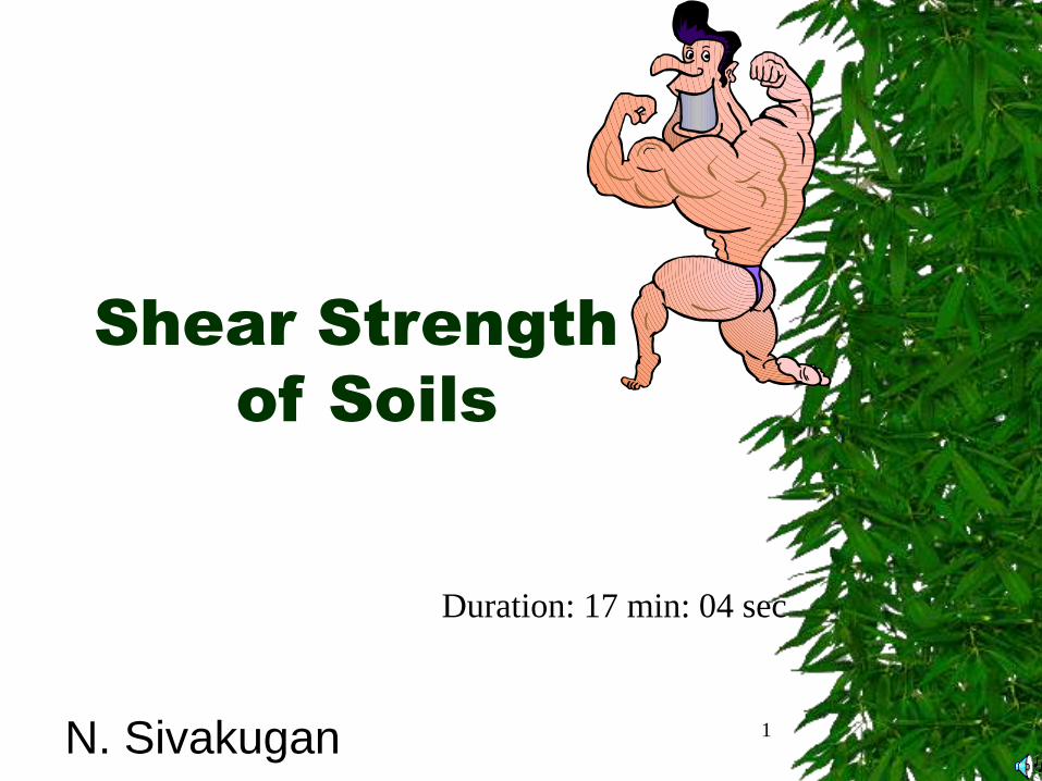
1
Shear Strength
of Soils
N. Sivakugan
Duration: 17 min: 04 sec
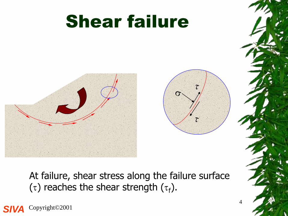
Shear failure
Soils generally fail in shear
strip footing
embankment
At failure, shear stress along the failure surface reaches the shear strength.
failure surface mobilised shear
resistance
SIVA Copyright©20013
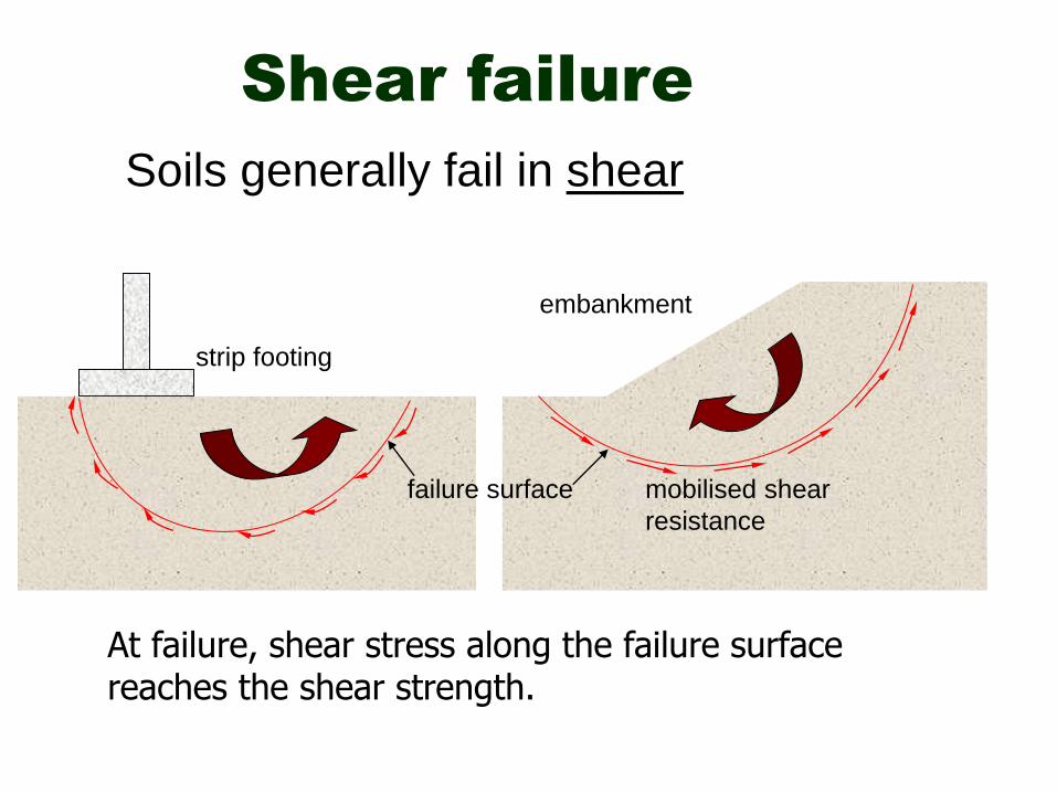
Shear failure
The soil grains slide over each other along the failure surface.
No crushing of individual grains.
failure surface
SIVA Copyright©20014
Shear failure
At failure, shear stress along the failure surface () reaches the shear strength (f).
SIVA Copyright©20015
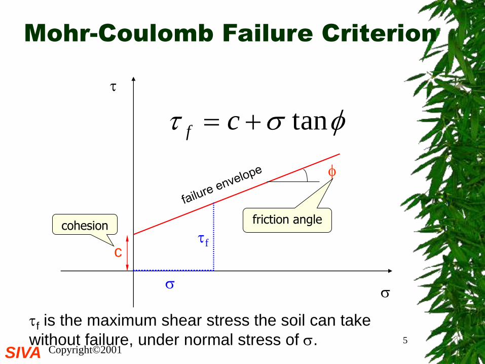
Mohr-Coulomb Failure Criterion
tan cf
c
cohesionfriction angle
f is the maximum shear stress the soil can take
without failure, under normal stress of .
f
SIVA Copyright©20016
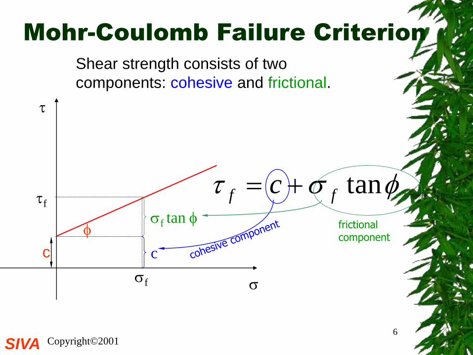
Mohr-Coulomb Failure Criterion
tanff c
Shear strength consists of two
components: cohesive and frictional.
f
f
c
f tan
c
frictional component
c and are measures of shear strength.
Higher the values, higher the shear strength.
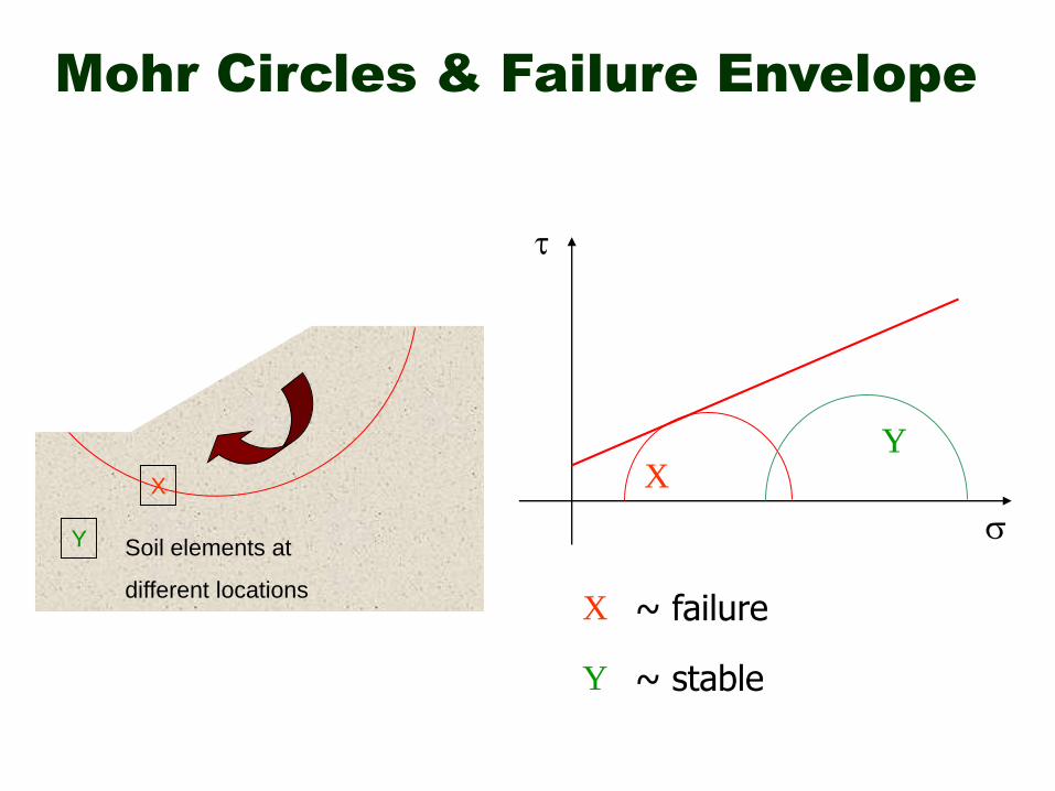
Mohr Circles & Failure Envelope
X
Y Soil elements at
different locations
XY
X
Y
~ failure
~ stable
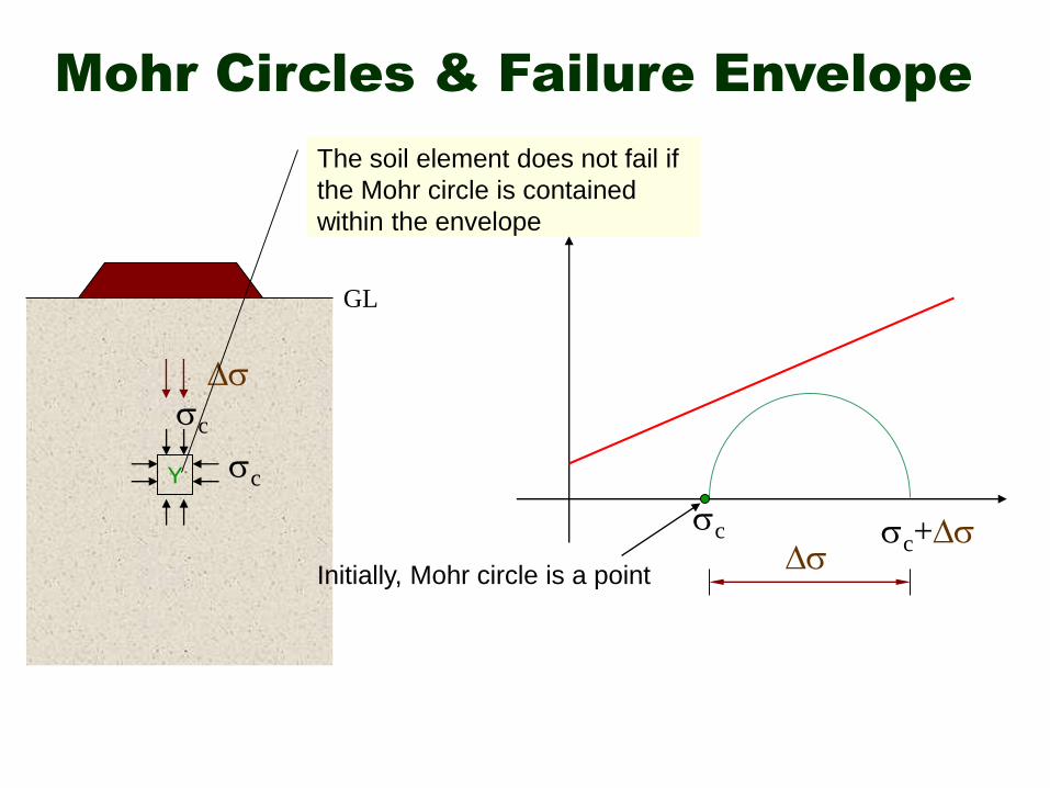
Mohr Circles & Failure Envelope
Y
Initially, Mohr circle is a point
c
c
c
c+
The soil element does not fail if
the Mohr circle is contained
within the envelope
GL
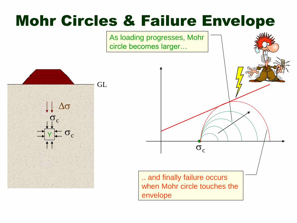
Mohr Circles & Failure Envelope
Y
c
c
c
GL
As loading progresses, Mohr
circle becomes larger…
.. and finally failure occurs
when Mohr circle touches the
envelope
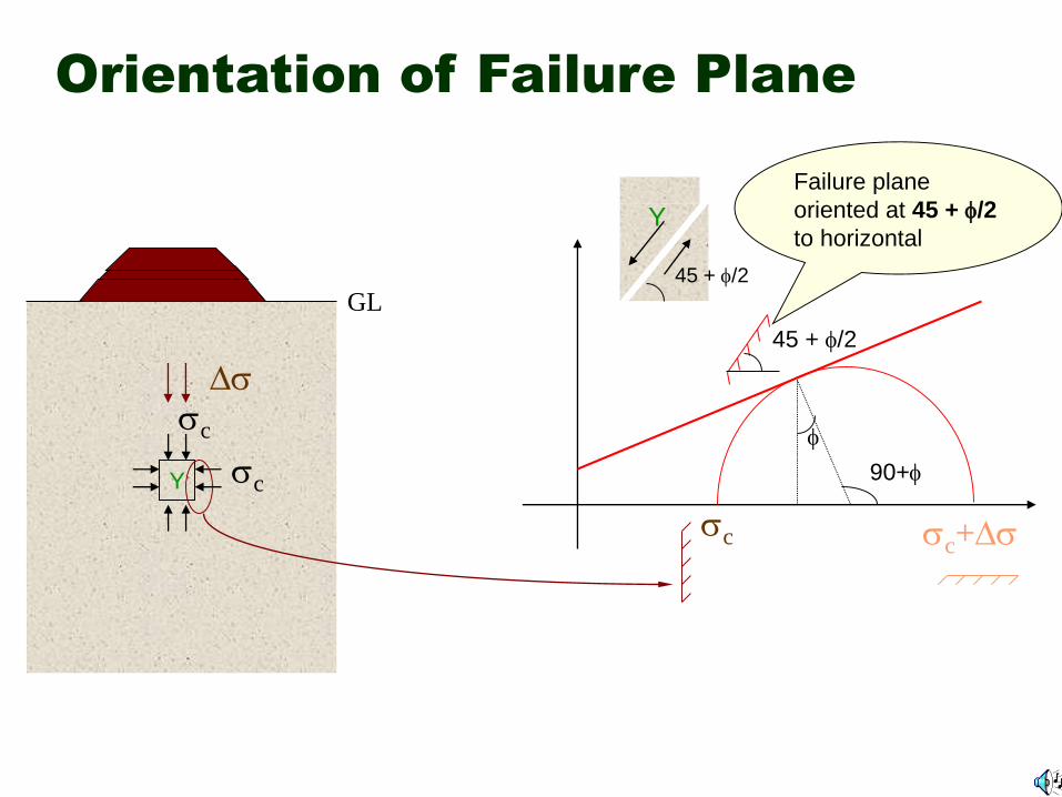
Orientation of Failure Plane
Y
c
c
c
GL
c+
90+
45 + /2
Failure plane
oriented at 45 + /2
to horizontal
45 + /2
Y
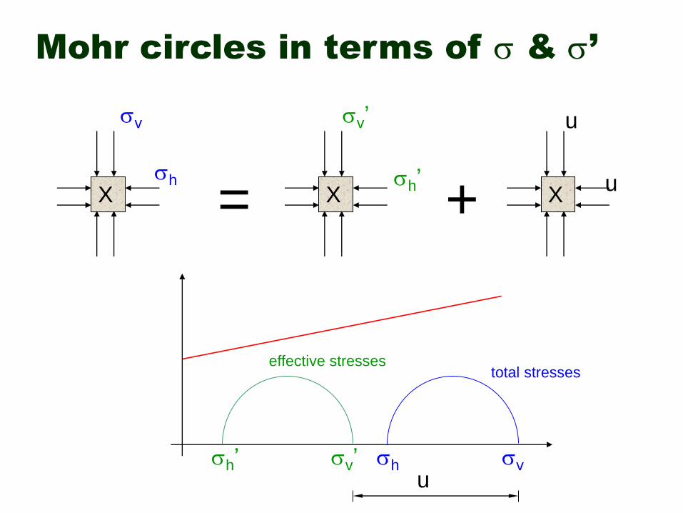
Mohr circles in terms of & ’
X X X
v
h
v’
h’
u
u
= +
total stresseseffective stresses
vhv’h’u
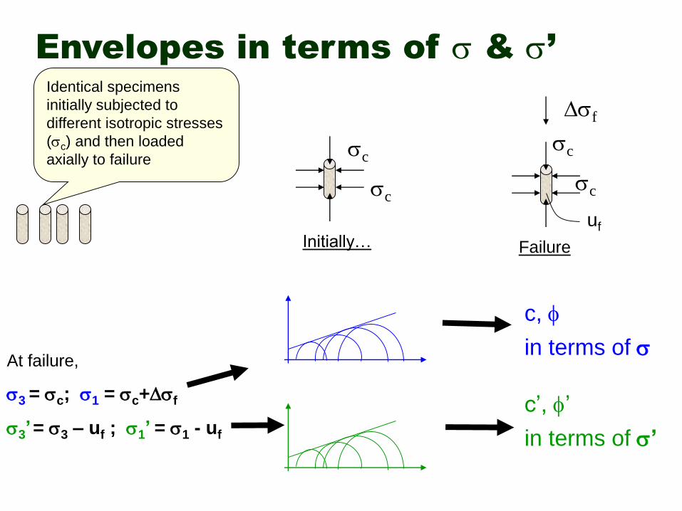
Envelopes in terms of & ’Identical specimens
initially subjected to
different isotropic stresses
(c) and then loaded
axially to failure
c
c
c
c
f
Initially… Failure
uf
At failure,
3 = c; 1 = c+f
3’= 3 – uf ; 1’ = 1 - uf
c,
c’, ’
in terms of
in terms of ’
SIVA Copyright©200114
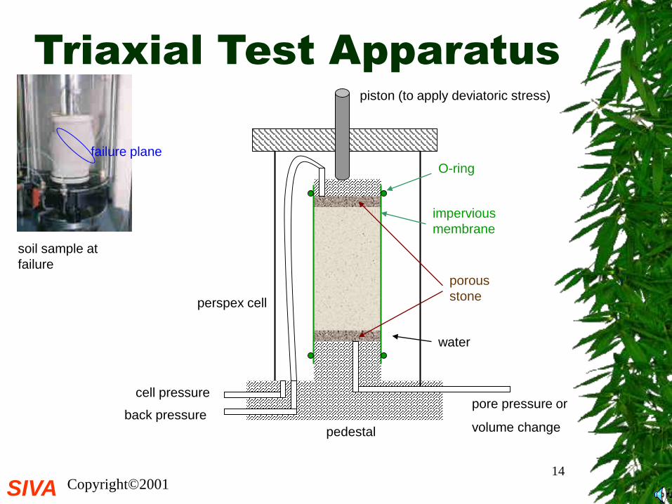
Triaxial Test Apparatus
porous
stone
impervious
membrane
piston (to apply deviatoric stress)
O-ring
pedestal
perspex cell
cell pressure
back pressurepore pressure or
volume change
water
soil sample at
failure
failure plane
SIVA Copyright©200115
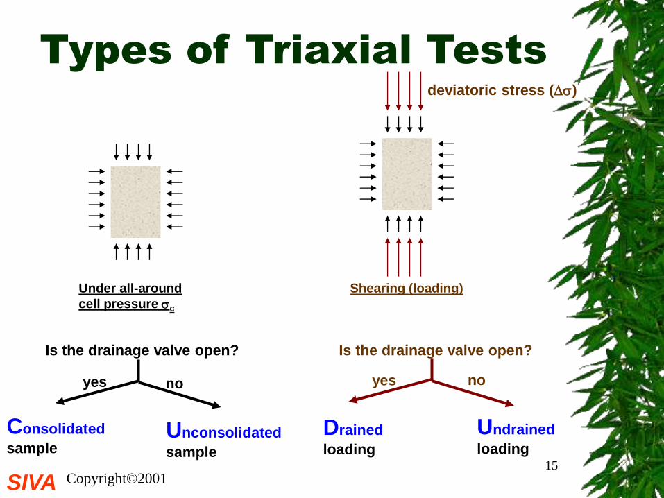
Types of Triaxial Tests
Under all-around
cell pressure c
Shearing (loading)
Is the drainage valve open? Is the drainage valve open?
deviatoric stress ()
yes no yes no
Consolidated
sampleUnconsolidated
sample
Drained
loading
Undrained
loading
SIVA Copyright©200116
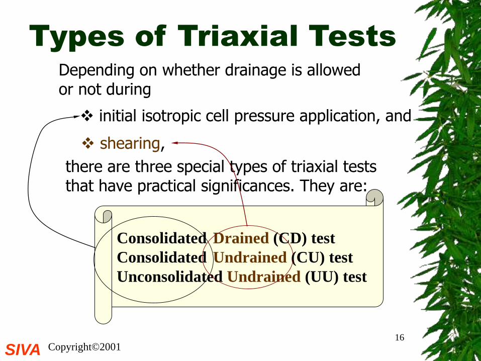
Types of Triaxial Tests
Depending on whether drainage is allowed or not during
initial isotropic cell pressure application, and
shearing,
there are three special types of triaxial tests that have practical significances. They are:
Consolidated Drained (CD) test
Consolidated Undrained (CU) test
Unconsolidated Undrained (UU) test
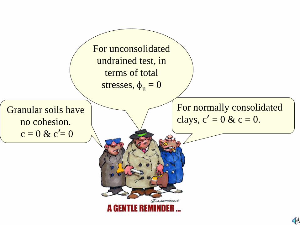
Granular soils have
no cohesion.
c = 0 & c’= 0
For normally consolidated
clays, c’ = 0 & c = 0.
For unconsolidated
undrained test, in
terms of total
stresses, u = 0
SIVA Copyright©200118
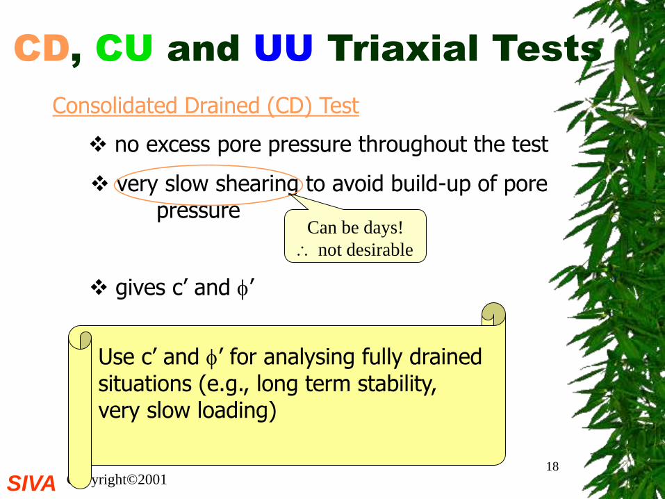
CD, CU and UU Triaxial Tests
no excess pore pressure throughout the test
very slow shearing to avoid build-up of pore pressure
Consolidated Drained (CD) Test
gives c’ and ’
Can be days!
not desirable
Use c’ and ’ for analysing fully drainedsituations (e.g., long term stability, very slow loading)
SIVA Copyright©200119
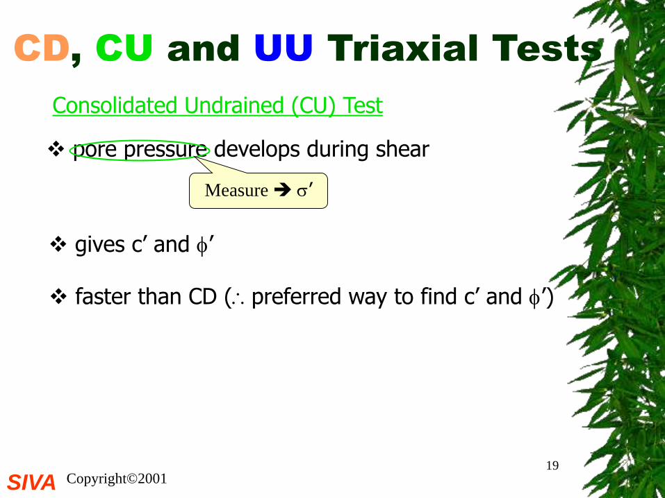
CD, CU and UU Triaxial Tests
pore pressure develops during shear
faster than CD (preferred way to find c’ and ’)
Consolidated Undrained (CU) Test
gives c’ and ’
Measure ’
SIVA Copyright©200120
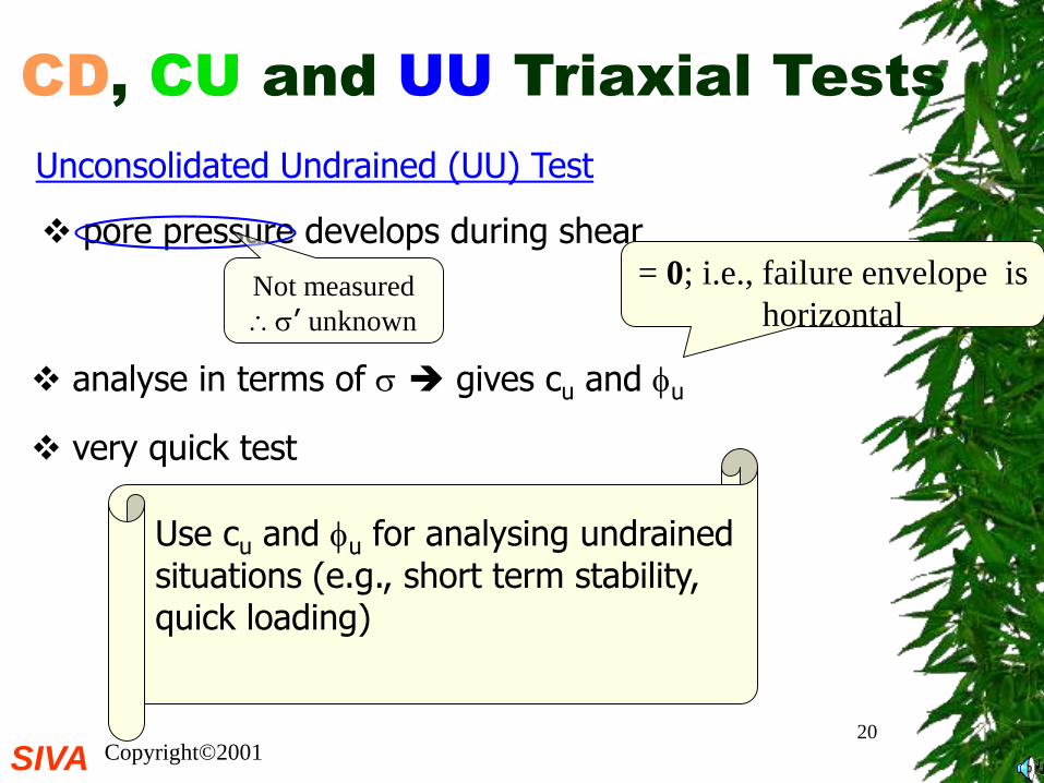
CD, CU and UU Triaxial Tests
pore pressure develops during shear
very quick test
Unconsolidated Undrained (UU) Test
analyse in terms of gives cu and u
Not measured
’ unknown
= 0; i.e., failure envelope is
horizontal
Use cu and u for analysing undrainedsituations (e.g., short term stability, quick loading)
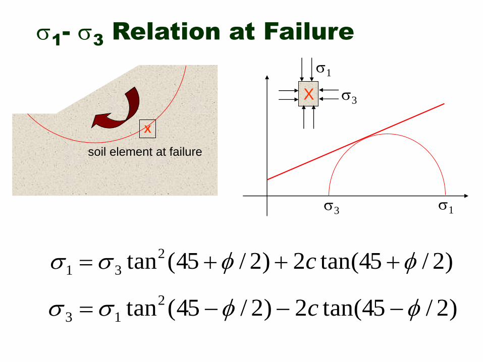
1-
3Relation at Failure
X
soil element at failure
3 1
X 3
1
)2/45tan(2)2/45(tan2
31 c
)2/45tan(2)2/45(tan2
13 c
SIVA Copyright©200122
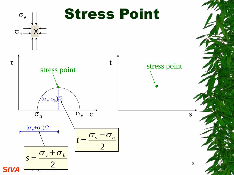
Stress Point
t
s
hv
(v-h)/2
(v+h)/2
stress pointstress point
2
hvs
2
hvt
X
v
h
SIVA Copyright©200123
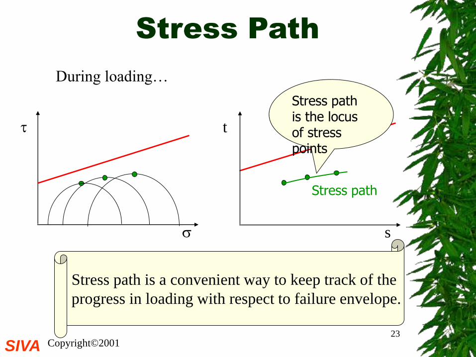
Stress Path
t
s
Stress path is the locus of stress points
Stress path
Stress path is a convenient way to keep track of the
progress in loading with respect to failure envelope.
During loading…
SIVA Copyright©200124
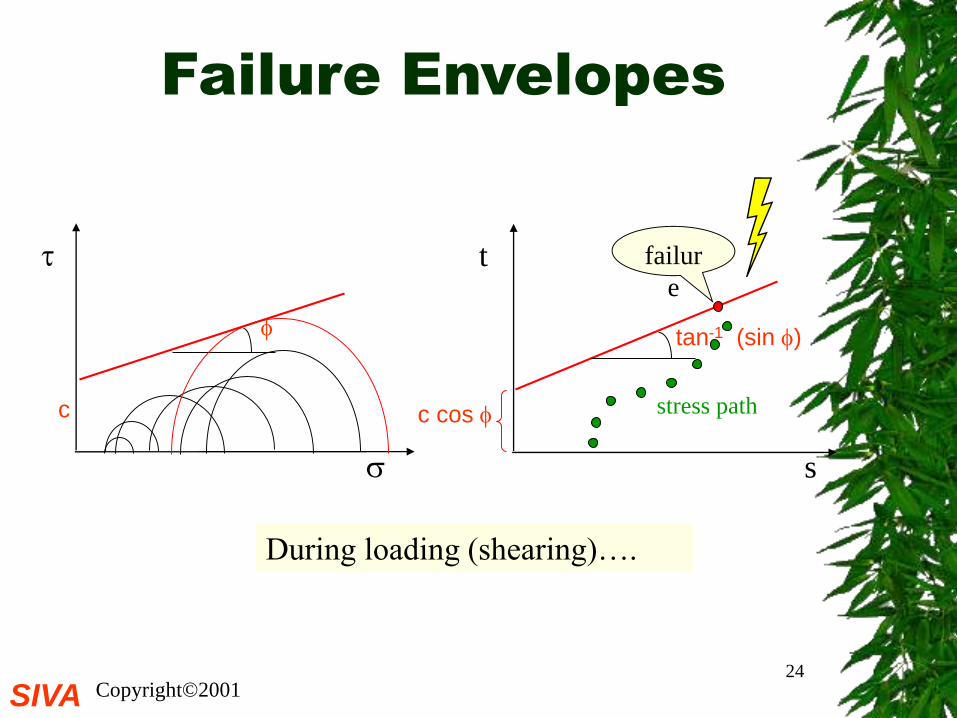
Failure Envelopes
t
s
c
c cos
tan-1 (sin )
failur
e
During loading (shearing)….
stress path
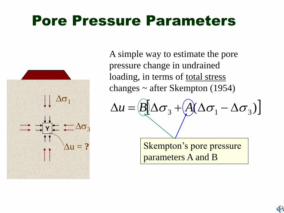
Pore Pressure Parameters
Y
1
3
u = ?
A simple way to estimate the pore
pressure change in undrained
loading, in terms of total stress
changes ~ after Skempton (1954)
)( 313 ABu
Skempton’s pore pressure
parameters A and B
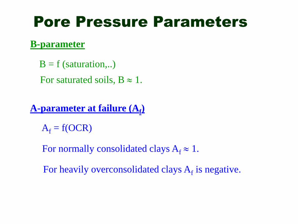
Pore Pressure Parameters
For saturated soils, B 1.
A-parameter at failure (Af)
For normally consolidated clays Af 1.
B-parameter
B = f (saturation,..)
Af = f(OCR)
For heavily overconsolidated clays Af is negative.