Strength of Materials- Statically Indeterminate Beam- Hani Aziz Ameen
Upload
hani-aziz-ameenCategory
view
277download
13description

Strength of Materials Handout No.2
Simple Stresses Asst. Prof. Dr. Hani Aziz Ameen Technical College- Baghdad Dies and Tools Eng. Dept. E-mail:[email protected]
www.mediafire.com/haniazizameen

Strength of Material -Handout No.2 - Simple Stresses - Dr. Hani Aziz Ameen
2-1 Introduction When a load is applied to a member of a machine or structure , the material distorts . The stress intensity ( usually abbreviated to stress) is the load transmitted per unit area of cross-section and the strain is a measure of the resulting distortion . 2-2 Definition of Stress
If a piece of material of cross-sectional area (A) is subjected to
equal and opposite axial force (P), either tensile as in Fig.(2-1a) or compressive as in Fig.(2-1b) , then the
area tionalsec crossforcestress
i.e. AP
Fig (2-1) Fig (2-2) From Fig (2-2) it can be explained that the internal force = A From the equilibrium
0Fy A P = 0
AP
The unit of stress is N/m2 , which is called Pascal [Pa]

Strength of Material -Handout No.2 - Simple Stresses - Dr. Hani Aziz Ameen
2-3 Kinds of Stresses 2-3-1 Simple Stresses (uniaxial stress)
When a force acts on a body in one direction the stresses induced are :
a) tensile stresses . b) compressive stresses c) shear stresses d) torsional stresses ( shear stresses). e) bending stresses .
according to the type of the applied load 2-3-2 Combined Stresses When the forces are in two or more directions ,as shown in Fig (2-3 a,b) the stresses induced are :
a) biaxial stress is when the applied loads are in two directions
(see Fig 2-3 a)
Fig (2-3a)
b) Tri axial stress is when the applied loads are in three directions (see Fig 2-3 b) Fig (2-3b)

Strength of Material -Handout No.2 - Simple Stresses - Dr. Hani Aziz Ameen
2-4 Tensile , Compressive & Shearing Stresses The differences between these three stresses are listed below :-
Item Tensile Stresses Compressive Stresses Shearing Stress 1 Tensile force acting on
the body tries to extend the dimension of the body in its direction as shown in Fig(2-4 a)
Compressive force acting on the body tries to shorten the dimension in its direction as shown in Fig(2-4 b)
Force acting on body tries to cut the body in its direction as shown in Fig(2-4 c)
2 The force is normal to the cross sectional area of the body
The force is normal to the cross sectional area of the body
The force is tangential to the cross-sectional area
3 This type of stress is called normal stress
This type of stress is called normal stress
This type of stress is called tangential stress
4 It is represented by:
AP
It is represented by:
AP
It is represented by:
AP
- a - - b - - c - Fig (2-4)

Strength of Material -Handout No.2 - Simple Stresses - Dr. Hani Aziz Ameen
2-4-1 Special Case of Tensile , Compressive & Shearing Stresses
There are other types of stresses: - 1-Bearing (Crushing) Stress ( b )
This special case of compressive stress occurs between bodies in contact and is subjected to compressive force. Also it occurs around rivets and bolts in connection joints. (see Fig. 2-5)
Fig (2-5)
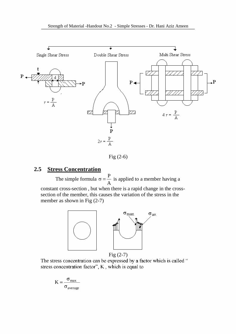
2-Classification of Shearing Stress in Bolts It can be stated that shearing stress in the bolts ise single shear stress , double shear stress and multi shear stress are shown in Fig (2-6).
Strength of Material -Handout No.2 - Simple Stresses - Dr. Hani Aziz Ameen
Fig (2-6)
2.5 Stress Concentration
The simple formula AP is applied to a member having a
constant cross-section , but when there is a rapid change in the cross-section of the member, this causes the variation of the stress in the member as shown in Fig (2-7)
Fig (2-7) The stress c
average
maxK

Strength of Material -Handout No.2 - Simple Stresses - Dr. Hani Aziz Ameen
The reasons for stress concentration are the existence of holes or grooves and any rapid changes in the member . Thus, the simple formula for tension & compression member is modified
to the form : APK
2-6 Examples
The following examples explain the different ideas of simple stress probles Example (2-1) Fig.(2-8) shows a bar of bronze , aluminum & steel subjected to axial loads . Find the stresses in the bronze , aluminum & steel .
Fig(2-8) Solution
(ten.) MPa 66.1610*60010*10
AF
6
3
s
(comp.) MPa 510*1000
10*5AF
6
3
al
and ,
(comp.) MPa 6.2810*70010*20
AF
6
3
b
Strength of Material -Handout No.2 - Simple Stresses - Dr. Hani Aziz Ameen
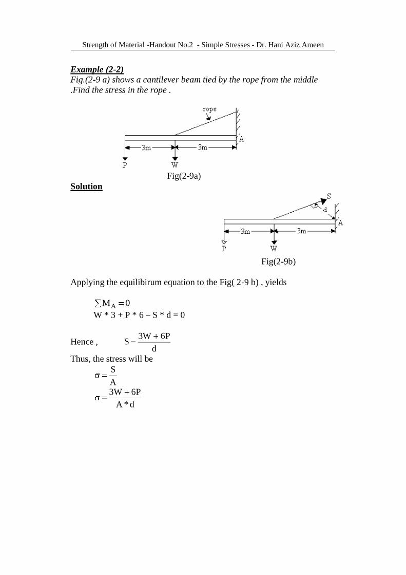
Example (2-2) Fig.(2-9 a) shows a cantilever beam tied by the rope from the middle .Find the stress in the rope .
Fig(2-9a) Solution
Fig(2-9b) Applying the equilibirum equation to the Fig( 2-9 b) , yields 0MA
W * 3 + P * 6 S * d = 0
Hence , d
P6W3S
Thus, the stress will be
AS
d*AP6W3

Strength of Material -Handout No.2 - Simple Stresses - Dr. Hani Aziz Ameen
Example (2-3) Fig.(2-10) shows a piston & cylinder, where the diameter of the piston is equal to 40 cm & a diameter of shaft ( piston rod) is equal to 5.6 cm. The inside value of gas pressure is 2 MPa . Find the direct tensile stress over the normal cross-section of the piston rod.
Fig(2-10) Solution It can be deduced the force F of the pressure P is
P*AF
P)6.540(4
F 22
from equilibrium condition 0Fx RF 0RF
hence, the stress will be :
MPa16.100P6.5
4
6.5404A
R2
22
Example (2-4) Fig.(2-11) shows a truss , which is subjected to force P at the joint B . Find the maximum P acting on the truss shown below if MPa 100max , A=30*60 mm2 for each section.
Fig(2-11)

Strength of Material -Handout No.2 - Simple Stresses - Dr. Hani Aziz Ameen
Solution
Taking a joint B
0cosSsinS0F 21x ............................... (i) PcosScosS0F 21y ................................ (ii)
Solving to get
sinsinSS 12 ................ (iii) , sub. into eq.(ii)
PcossinsinScosS 11
Psin
cossinsincosS1
)sin(sinPS P
sin)sin(S 11 Sub. into eq. (iii) ,yield
)sin(sinP
sinsin
)sin(sinPS2
The stress induced in the cross-section is
max1
1 AS

Strength of Material -Handout No.2 - Simple Stresses - Dr. Hani Aziz Ameen
maxmax
)sin(sin
AP
sin)sin(.A.P maxmax
From tri-geometric relation it can be get & that
82=62+102 2*6*10 cos cos = 0.6
and 75.268
1.53sin6
sin8
sin6
sin
and 9.30 8
cos6sin
)(180 180=26.75+53.1+( +36.9) =63.25° thus Pmax will be
sin36.936.9)sin(63.25 10*60*30*10*100P 66
max
Pmax = 295.3 kN
Strength of Material -Handout No.2 - Simple Stresses - Dr. Hani Aziz Ameen
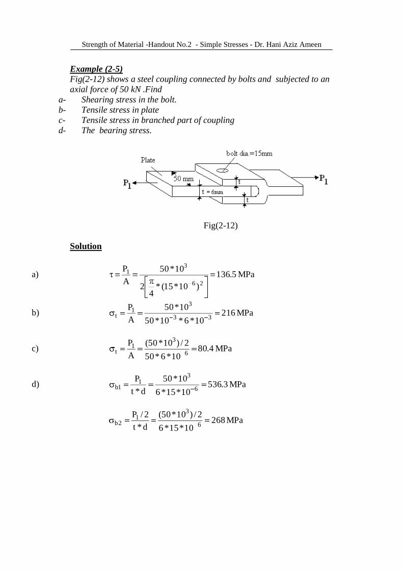
Example (2-5) Fig(2-12) shows a steel coupling connected by bolts and subjected to an axial force of 50 kN .Find
a- Shearing stress in the bolt. b- Tensile stress in plate c- Tensile stress in branched part of coupling d- The bearing stress.
Fig(2-12) Solution
a) MPa 5.136)10*15(*
42
10*50AP
26
31
b) MPa 21610*6*10*50
10*50AP
33
31
t
c) MPa 4.8010*6*50
2/)10*50(AP
6
31
t
d) MPa 3.53610*15*6
10*50d*t
P6
31
1b
MPa 26810*15*6
2/)10*50(d*t2/P
6
31
2b

Strength of Material -Handout No.2 - Simple Stresses - Dr. Hani Aziz Ameen
Example (2-6) Fig.(2-13) shows a rectangular plate fixed at the four corners . A 160 kN is applied at the center of the plate . Find :
a) The stress across the lower washer before tightening the nut b) The stress across the upper and lower washers after tightening the
nut and the tensile force across the bolt = 5 kN
Fig(2-13) Solution
a) Load at each corner 4
160 = 40 kN
hence, the compressive stress , is
2
22
3
c mm/MN3.25)2250(
4
10*40AF
b) Stress on upper washer
2
22c mm/MN 7.5
)3240(4
5
and the stress on lower washer can be obtained The total force on the lower washer = 40+5 = 45 kN Thus,
2
22c mm/MN9.28
)2250(4
45

Strength of Material -Handout No.2 - Simple Stresses - Dr. Hani Aziz Ameen
Example (2-7) Fig.(2-14) shows the pin connected structure. Pin C & D each 31.75 mm diameter ; pin C is in single shear and pin D is in double shear. Find the shear stress in the pins C&D and the bearing stress between the pin at A and the plate E . The thickness of the plate E is 6.35 mm .
Fig(2-14) Solution. From Equilibrium conditions
kN8.17H022.1*271.82*H 0MD kN4.53F022.1*F65.3*8.170MA

Strength of Material -Handout No.2 - Simple Stresses - Dr. Hani Aziz Ameen
The resultant reaction at pin C= kN26.56)4.53()8.17( 22
Pin C acting in single shear , hence , MPa71)75.31(
4
10*25.562
3
The resultant reaction at pin D= kN08.54)4.53()9.8( 22
Pin, D acts in double shear , hence, MPa16.35)75.31(
4*2
10*08.542
3
The resultant reaction at pin A= kN 85.35)6.35()448.4( 22 Half of this reaction acts at the upper plate and the other half acts at the lower plate E, thus the bearing stress will be :
MPa8910*75.31*10*35.6
2/)10*85.35(33
3
b
Example (2-8) Fig (2-15) shows a lever keyed to a shaft and subjected to the forces. Find the length L of the key for an allowable shearing stress of 69 MPa
Fig(2-15) Solution Torque acting on the shaft ,T, can be calculated
T =2*355.84*304.8*10 3 = 216.92 kN.m

Strength of Material -Handout No.2 - Simple Stresses - Dr. Hani Aziz Ameen
T = F*r 216.92 = F*(25.4/2) F = 17 kN
Hence , the shear stress will be :
L35.610*17
AF 3
mm11.39LL35.6
10*1710*693
6
Example (2-9) Fig.(2-16) shows the wooden truss, the allowable shearing stress parallel to the grains is 0.6895 MPa and the allowable bearing stress is 3.44 MPa . The cross-sectional area of each member is 152.4 mm*152.4 mm . Find the distance a & b .
Fig(2-16) Solution From the Equilibrium condition
0MA
R2*L1+61.6*103 * L2 * cos30=0 .............(i) substituting L1 = L2/cos30 into eq.(i) , gives

Strength of Material -Handout No.2 - Simple Stresses - Dr. Hani Aziz Ameen
R2 = 46.22 kN , and R1 = 61.6 46.22 R1 = 15.4 kN
From Section a-a 0Mc 46.22*L3*cos60 + FAB* L * sin60 = 0
FAB = 26.7 kN (ten.) Hence , the shear stress will be
AP , P = H = FAB = 26.7 kN
And the shearing area A = 152.4*a mm2 Thus,
mm254aa*10*4.152
10*7.2610*6895.0 3
36
Then , the bearing stress is AP
bearing , P = H = 26.7 kN
And the bearing area A = 152.4*b Thus
mm8.50bb*10*4.152
10*7.2610*44.3 3
36
Example (2 10) Fig (2-17) shows a flat bar having the dimensions and geometric shape shown in the Fig. is subjected to a tensile force P . Find the following ,with r=6.35 mm
a) the average stresses at the critical sections when the applied load P=22.24 kN and the thickness of the bar t=12.7 mm
b) the max. stress at the change in the cross section accounting for the stress concentration also, sketch the stress distribution and show the computed values on a sketch The stress concentration factor are K=2.45 for circular hole K=2.15 for the semi-circular grooves K=1.7 for the fillets Fig(2-17)

Strength of Material -Handout No.2 - Simple Stresses - Dr. Hani Aziz Ameen
Solution
a) MPa 98.4510*7.12*7.12
1000*24.22AP
6av
b) The max. stress are :
MPa67.11298.45*45.2APK) hole circularmax
MPa6.9898.45*15.2)hole
arSemicirculmax
MPa 9.7798.45*7.1)filletmax Example (2-11) Fig.(2-18) shows a bar having the force P=30 kN acting axially . Find the max. stress for the fillet for K=1.63, K=1.97, and K =2.46 Solution
MPa5.6210*48
30000AP
av
thus , the max. stress will be MPa1025.62*63.1K avmax
MPa1235.62*97.1max MPa1545.62*46.2max
Fig(2-18)

Strength of Material -Handout No.2 - Simple Stresses - Dr. Hani Aziz Ameen
2.7 Problems
2-1) Fig (2-19) shows a bar with variable cross- section with axial load P = 10kN , and L = 0.3 m , d = 0.01 m, dx = (0.01+x2) m , Find x at x = 0 , x = L / 6 & x = L/3.
Fig(2-19) 2-2) Fig.(2-20) shows a round bar subjected to a tensile load of
150 kN. If the stress 215 MPa , find the diameter of the middle portion.
Fig(2-20)
2-3) Fig(2-21) shows a cast column of the section 2 m high and it supports a load of 20kN , in addition to its own weight. Find the max. compressive stress in the column . The density of cast iron is 7200 kg/m3 .
Fig(2-21)

Strength of Material -Handout No.2 - Simple Stresses - Dr. Hani Aziz Ameen
2-4) Fig(2-22) shows the plates fixed with a bolt , subjected to an axial load P where P=39240 N, MPa157 , MPa7.117 , MPa314bearing , Find d , t , a & b.
Fig(2-22) 2-5) Fig (2-23) shows a member is subjected to a force 31392 N ,
the stresses are MPa81.9 , = 0.7 , b=2 . Find t , d, b , do .
Fig(2-23)

Strength of Material -Handout No.2 - Simple Stresses - Dr. Hani Aziz Ameen
2-6) Fig.(2-24) shows a mechanism supports the hydraulic cylinder and
weighs 26688 N and the average normal stress in the 19mm diameter plunger of hydraulic cylinder . Find the average shearing stress in the 12.7mm diameter pin at A
Fig(2-24) 2-7) Fig.(2-25) shows a mechanism, the hub of the pulley is 12mm thick .
Find the shearing stress in the 6 mm diameter pin at the pulley and the average bearing stress between the pulley and the pin
Fig(2-25)

Strength of Material -Handout No.2 - Simple Stresses - Dr. Hani Aziz Ameen
2-8) Fig.(2-26) shows a knuckle joint in a tie bar allowing stresses of
105, 75 and 150 MPa for tension , shearing and bearing respectively. Find suitable dimensions for D , d1, t and d2 . if the load on the rod is 125 kN.
Fig(2-26) 2-9) Fig(2-27) shows the beam BE is used for hoisting machinery . It is
anchored by two bolts at B, and C , it rests on a parapet wall . The essential details are given in the fig. Note that the bolts are threaded as shown in Fig. with d=16 mm at the root of the threads . If this arrangement is used to lift equipment of 10 kN , find the stress in the bolts BD and the bearing stress at C . Assume that the weight of the beam is negligible in comparison with the loads handled .
Fig(2-27)
Strength of Material -Handout No.2 - Simple Stresses - Dr. Hani Aziz Ameen
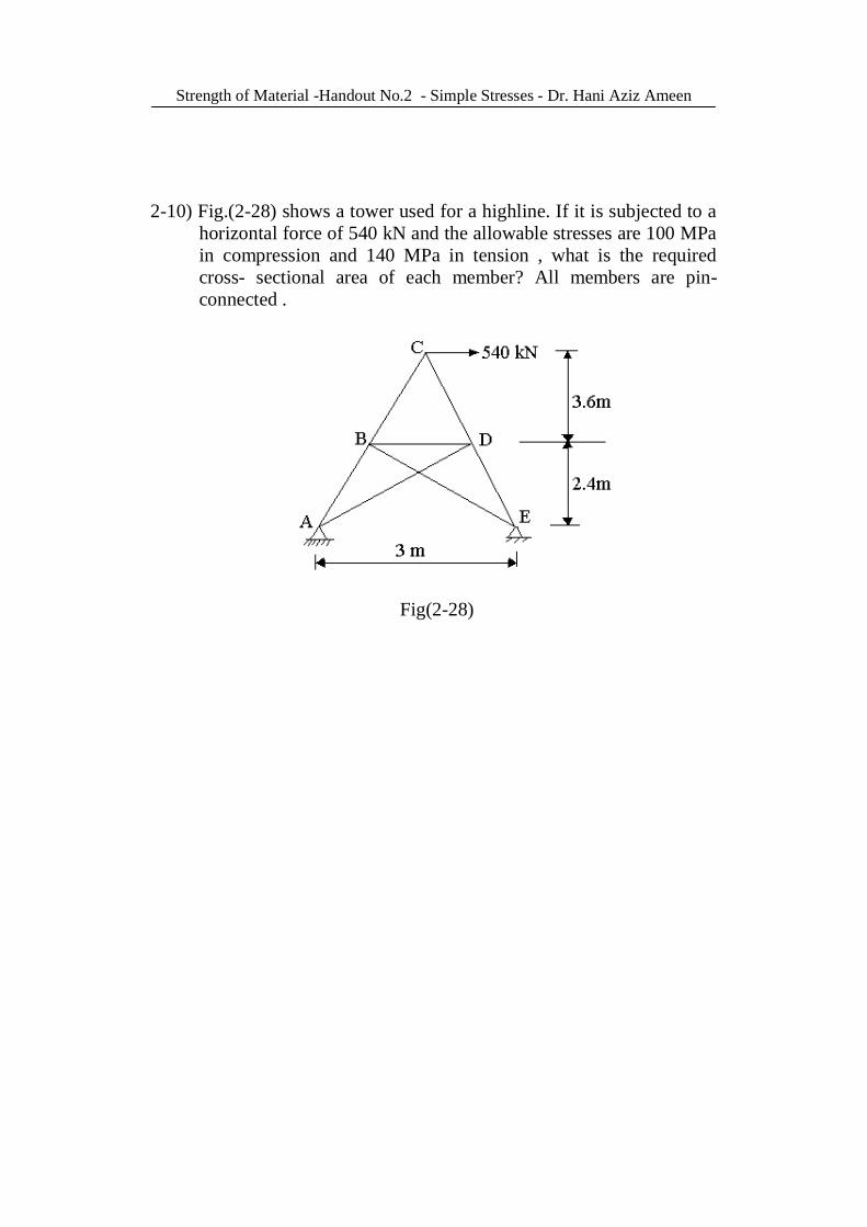
2-10) Fig.(2-28) shows a tower used for a highline. If it is subjected to a
horizontal force of 540 kN and the allowable stresses are 100 MPa in compression and 140 MPa in tension , what is the required cross- sectional area of each member? All members are pin-connected .
Fig(2-28)