Strength, Durability, and Application of Grouted …...Strength, Durability, and Application of...
89
Strength, Durability, and Application of Grouted Couplers for Integral Abutments in Accelerated Bridge Construction Final Report October 2016 Sponsored by Federal Highway Administration Accelerated Bridge Construction University Transportation Center U.S. Department of Transportation Office of the Assistant Secretary for Research and Technology Iowa Department of Transportation (Part of InTrans Project 12-441)
Transcript of Strength, Durability, and Application of Grouted …...Strength, Durability, and Application of...

Strength, Durability, and Application of Grouted Couplers for Integral Abutments in Accelerated Bridge Construction Final ReportOctober 2016
Sponsored byFederal Highway AdministrationAccelerated Bridge Construction University Transportation CenterU.S. Department of Transportation Office of the Assistant Secretary for Research and TechnologyIowa Department of Transportation(Part of InTrans Project 12-441)

About the ABC-UTC The Accelerated Bridge Construction University Transportation Center (ABC-UTC) is a Tier 1 UTC sponsored by the U.S. Department of Transportation Office of the Assistant Secretary for Research and Technology (USDOT/OST-R). The mission of ABC-UTC is to reduce the societal costs of bridge construction by reducing the duration of work zones, focusing special attention on preservation, service life, construction costs, education of the profession, and development of a next-generation workforce fully equipped with ABC knowledge.
About the BECThe mission of the Bridge Engineering Center (BEC), which is part of the Institute for Transportation (InTrans) at Iowa State University, is to conduct research on bridge technologies to help bridge designers/owners design, build, and maintain long-lasting bridges. The mission of InTrans is to develop and implement innovative methods, materials, and technologies for improving transportation efficiency, safety, reliability, and sustainability while improving the learning environment of students, faculty, and staff in transportation-related fields.
ISU Non-Discrimination Statement Iowa State University (ISU) does not discriminate on the basis of race, color, age, ethnicity, religion, national origin, pregnancy, sexual orientation, gender identity, genetic information, sex, marital status, disability, or status as a U.S. veteran. Inquiries regarding non-discrimination policies may be directed to Office of Equal Opportunity, Title IX/ADA Coordinator, and Affirmative Action Officer, 3350 Beardshear Hall, Ames, Iowa 50011, 515-294-7612, email [email protected].
NoticeThe contents of this report reflect the views of the authors, who are responsible for the facts and the accuracy of the information presented herein. The opinions, findings and conclusions expressed in this publication are those of the authors and not necessarily those of the sponsors.
This document is disseminated under the sponsorship of the U.S. DOT UTC program in the interest of information exchange. The sponsors assume no liability for the contents or use of the information contained in this document. This report does not constitute a standard, specification, or regulation.
The sponsors do not endorse products or manufacturers. If trademarks or manufacturers’ names appear in this report, it is only because they are considered essential to the objective of the document.
Quality Assurance StatementThe Federal Highway Administration (FHWA) provides high-quality information to serve Government, industry, and the public in a manner that promotes public understanding. Standards and policies are used to ensure and maximize the quality, objectivity, utility, and integrity of its information. The FHWA periodically reviews quality issues and adjusts its programs and processes to ensure continuous quality improvement.
Iowa DOT Statements Federal and state laws prohibit employment and/or public accommodation discrimination on the basis of age, color, creed, disability, gender identity, national origin, pregnancy, race, religion, sex, sexual orientation or veteran’s status. If you believe you have been discriminated against, please contact the Iowa Civil Rights Commission at 800-457-4416 or the Iowa Department of Transportation affirmative action officer. If you need accommodations because of a disability to access the Iowa Department of Transportation’s services, contact the agency’s affirmative action officer at 800-262-0003.
The preparation of this report was financed in part through funds provided by the Iowa Department of Transportation through its “Second Revised Agreement for the Management of Research Conducted by Iowa State University for the Iowa Department of Transportation” and its amendments.
The opinions, findings, and conclusions expressed in this publication are those of the authors and not necessarily those of the Iowa Department of Transportation or the U.S. Department of Transportation Federal Highway Administration.
Technical Report Documentation Page
1. Report No. 2. Government Accession No. 3. Recipient’s Catalog No.
Part of InTrans Project 12-441
4. Title and Subtitle 5. Report Date
Strength, Durability, and Application of Grouted Couplers for Integral
Abutments in Accelerated Bridge Construction
October 2016
6. Performing Organization Code
7. Author(s) 8. Performing Organization Report No.
Travis Hosteng, Brent Phares, and Sam Redd
9. Performing Organization Name and Address 10. Work Unit No. (TRAIS)
Bridge Engineering Center
Iowa State University
2711 S. Loop Drive, Suite 4700
Ames, IA 50010-8664
11. Contract or Grant No.
DTRT13-G-UTC41
12. Sponsoring Organization Name and Address 13. Type of Report and Period Covered
Accelerated Bridge Construction
University Transportation Center
Florida International University
10555 W. Flagler Street, EC 3680
Miami, FL 33174
Iowa Department of Transportation
800 Lincoln Way
Ames, IA 50010
U.S. Department of Transportation
Office of the Assistant Secretary for
Research and Technology
and Federal Highway Administration
1200 New Jersey Avenue, SE
Washington, DC 20590
Final Report
14. Sponsoring Agency Code
SPR RB19-014 and SPR RB07-013
15. Supplementary Notes
Visit www.intrans.iastate.edu for color pdfs of this and other research reports.
16. Abstract
As accelerated bridge construction (ABC) has gained the attention of the bridge community, certain bridge types, such as integral
abutment bridges, have seen limited use. Integral abutments eliminate the expansion joint from the bridge superstructure by
rigidly connecting the superstructure and foundation. The integral abutment is therefore often large and heavily reinforced, which
presents challenges for ABC projects.
This research investigated integral abutment details for use in ABC projects through mechanical splicing of the integral
diaphragm and the pile cap. Two ABC details, the grouted reinforcing bar coupler detail and the pile coupler detail, were
evaluated in the laboratory for constructability, strength, and durability. A typical cast-in-place detail was also constructed and
tested as a baseline.
For the grouted reinforcing bar coupler detail, a plywood template was used to “match cast” the pile cap and the integral
diaphragm. The template was simple to construct and resulted in the successful alignment of 17 spliced steel bars and grouted
couplers over an 8 foot specimen. Though the grouting of two couplers was obstructed, more than adequate strength was created
by the connection, and the crack width at the precast joint was comparable to that of the cast-in-place specimen.
The pile coupler reduced the number of spliced connections between the pile cap and integral diaphragm sufficiently to facilitate
adequate construction tolerances. The splicing system worked well during construction, but the detail’s strength and durability
was less than ideal. Several lessons were learned from these tests that could improve the structural performance of the pile
coupler detail.
17. Key Words 18. Distribution Statement
accelerated bridge construction—bridge superstructure—cast-in-place detail—
grouted coupler—integral abutment constructability—integral abutment durability—integral abutment strength—pile coupler—splicing system
No restrictions.
19. Security Classification (of this
report)
20. Security Classification (of this
page)
21. No. of Pages 22. Price
Unclassified. Unclassified. 87 NA
Form DOT F 1700.7 (8-72) Reproduction of completed page authorized


STRENGTH, DURABILITY, AND APPLICATION OF
GROUTED COUPLERS FOR INTEGRAL ABUTMENTS
IN ACCELERATED BRIDGE CONSTRUCTION
Final Report
October 2016
Principal Investigator
Brent M. Phares, Director
Bridge Engineering Center, Iowa State University
Co-Principal Investigator
Terry J. Wipf, Bridge Engineer
Bridge Engineering Center, Iowa State University
Research Assistant
Sam Redd
Authors
Travis Hosteng, Brent Phares, and Sam Redd
Sponsored by
Iowa Department of Transportation,
Federal Highway Administration,
Accelerated Bridge Construction University Transportation Center, and
U.S. Department of Transportation
Office of the Assistant Secretary for Research and Technology
Preparation of this report was financed in part
through funds provided by the Iowa Department of Transportation
through its Research Management Agreement with the
Institute for Transportation
(Part of InTrans Project 12-441)
A report from
Institute for Transportation
Iowa State University
2711 South Loop Drive, Suite 4700
Ames, IA 50010-8664
Phone: 515-294-8103 / Fax: 515-294-0467
www.intrans.iastate.edu


v
TABLE OF CONTENTS
ACKNOWLEDGMENTS ............................................................................................................. ix
EXECUTIVE SUMMARY ........................................................................................................... xi
CHAPTER 1. INTRODUCTION ....................................................................................................1
1.1 Background ....................................................................................................................1 1.2 Research Scope, Objectives, and Tasks .........................................................................2
CHAPTER 2. LITERATURE REVIEW .........................................................................................3
2.1 Connection Details for Prefabricated Bridge Elements and Systems (2009) ................3
2.2 Accelerated Bridge Construction Manual (2011) ..........................................................5
2.3 Innovative Bridge Designs for Rapid Renewal ABC Toolkit (2014) ............................5 2.4 Laboratory and Field Testing of and Accelerated Bridge Construction
Demonstration (2013) ....................................................................................................7
2.5 Plastic Energy Absorption Capacities of #18 Reinforcing Bar Splices under
Monotonic Loading (1994) ............................................................................................7
2.6 Evaluation of Grout-Filled Mechanical Splices for Precast Concrete
Construction (2008) .......................................................................................................8 2.7 High Strain-Rate Testing of Mechanical Couplers (2009) ............................................9
2.8 Precast Column-Footing Connections for ABC in Seismic Zones (2013) ....................9 2.9 Laboratory Connection Details for Grouted Coupler Connection Details for
ABC Projects (2015) ....................................................................................................10
CHAPTER 3. ABC INTEGRAL ABUTMENT DETAILS ..........................................................12
3.1 Cast-in-Place ................................................................................................................12 3.2 Grouted Reinforcing Bar Coupler ................................................................................15
3.3 Pile Coupler .................................................................................................................18
CHAPTER 4. CONSTRUCTION .................................................................................................23
4.1 Cast in Place Specimen ................................................................................................23
4.2 Grouted Reinforcing Bar Coupler Specimen ...............................................................25 4.3 Pile Coupler Specimen .................................................................................................36
CHAPTER 5. LABORATORY TESTING ...................................................................................49
5.1 Methodology ................................................................................................................49 5.2 Instrumentation ............................................................................................................52 5.3 Results ..........................................................................................................................56
5.3.1 Cast in Place ........................................................................................................58 5.3.2 Grouted Reinforcing Bar Coupler .......................................................................60 5.3.3 Pile Coupler ........................................................................................................63
5.3.4 Foundation Pile Strength.....................................................................................68
CHAPTER 7. SUMMARY ............................................................................................................72
REFERENCES ..............................................................................................................................75

vi
LIST OF FIGURES
Figure 1. Integral abutment with closure pour .................................................................................3 Figure 2. Grouted coupler conceptual drawing ................................................................................4
Figure 3. Three-dimensional drawing of integral abutment with closure pour ...............................5 Figure 4. Integral abutment with bar dowels ...................................................................................6 Figure 5. Grouted reinforcing bar coupler joining precast deck and abutment ...............................8 Figure 6. Grouted reinforcing bar coupler precast laboratory specimen .......................................10 Figure 7. Integral abutment plan view from Iowa DOT ................................................................13
Figure 8. Integral abutment section view from Iowa DOT ............................................................13 Figure 9. Cast-in-place specimen plan view ..................................................................................14 Figure 10. Cast-in-place specimen section view ............................................................................14 Figure 11. Prefabricated bridge elements and systems (PBES) using integral abutment
with grouted reinforcing bar couplers ................................................................................15 Figure 12. Precast pile cap .............................................................................................................16
Figure 13. Grouted coupler section view through couplers ...........................................................17 Figure 14. Grouted coupler section view through girder ...............................................................18 Figure 15. Slide-in bridge using pile couplers ...............................................................................19
Figure 16. Plan view pile coupler ..................................................................................................19 Figure 17. Section view A - pile coupler .......................................................................................20
Figure 18. Section view B - pile coupler .......................................................................................20 Figure 19. Section view C - pile coupler .......................................................................................21 Figure 20. Cast-in-place pile cap ...................................................................................................23
Figure 21. Cast-in-place integral diaphragm .................................................................................24 Figure 22. Cast-in-place integral abutment specimen ....................................................................25
Figure 23. Pile cap reinforcing bar, formwork, and pour ..............................................................26 Figure 24. Grouted coupler pile cap ..............................................................................................26
Figure 25. Grouted coupler template .............................................................................................27 Figure 26. Form plug .....................................................................................................................28
Figure 27. Grouted coupler and reinforcing bar ............................................................................29 Figure 28. Integral diaphragm and deck, formwork, and reinforcing bar ......................................30 Figure 29. Integral diaphragm ........................................................................................................31
Figure 30. Seal plug .......................................................................................................................32 Figure 31. Neoprene disk, seal plug, and shim ..............................................................................32
Figure 32. Integral diaphragm placement ......................................................................................33 Figure 33. Grout bed formwork .....................................................................................................33 Figure 34. Grout hand pump ..........................................................................................................34 Figure 35. Completed grout bed and coupler grouting ..................................................................35
Figure 36. Grouted coupler layout .................................................................................................36 Figure 37. Pile cap reinforcing steel bar cage ................................................................................37 Figure 38. Pile cap reinforcing bar, formwork, and CMP .............................................................38
Figure 39. CMP void in pile cap ....................................................................................................38 Figure 40. CMP lid with reinforcing bar guides and U-bolt ..........................................................39 Figure 41. CMP with lid ................................................................................................................40 Figure 42. HP section with threaded rods ......................................................................................40 Figure 43. Integral diaphragm reinforcing bar cage ......................................................................41
vii
Figure 44. Side view of CMP void ................................................................................................42 Figure 45. Integral diaphragm deck reinforcing bar ......................................................................43 Figure 46. Integral diaphragm with suspended HP sections ..........................................................44
Figure 47. Suspended HP sections .................................................................................................44 Figure 48. Pile cap with backer rod seal ........................................................................................45 Figure 49. Grout bed formwork back ............................................................................................46 Figure 50. Grout bed formwork front ............................................................................................46 Figure 51. Grout funnel system .....................................................................................................47
Figure 52. Bleed water passing through the grout bed ..................................................................48 Figure 53. Three-dimensional drawing of laboratory test setup, front ..........................................49 Figure 54. Three-dimensional drawing of laboratory test setup, rear ............................................49 Figure 55. Laboratory loading and horizontal and vertical actuators ............................................50 Figure 56. Thermal contraction and free body diagram ................................................................51
Figure 57. Live load and free body diagram ..................................................................................51 Figure 58. Thermal expansion and free body diagram ..................................................................52
Figure 59. Plan view for horizontal loading, all specimens ...........................................................53 Figure 60. Grouted coupler and cast-in-place instrumentation plan view for vertical
loading................................................................................................................................53 Figure 61. Pile coupler instrumentation plan view for vertical loading ........................................54
Figure 62. Front face of the abutment during horizontal loading ..................................................55 Figure 63. Rear face of abutment for horizontal loading ...............................................................55 Figure 64. HP instrumentation .......................................................................................................56
Figure 65. Displacement transducer numbering ............................................................................57 Figure 66. Reinforcing bar strain gauge numbering ......................................................................57
Figure 67. Crack versus applied moment from horizontal load.....................................................58
Figure 68. Crack width versus moment from vertical load ...........................................................59
Figure 69. Tension reinforcing bar stress versus moment from vertical load ...............................60 Figure 70. Crack width versus moment from horizontal load .......................................................61
Figure 71. Crack width versus moment from vertical load ...........................................................62 Figure 72. Crack between grout bed and diaphragm .....................................................................62 Figure 73. Tension reinforcing bar stress versus moment from vertical load ...............................63
Figure 74. Crack versus moment from horizontal load .................................................................64 Figure 75. Crack width versus moment from vertical load ...........................................................64
Figure 76. Pile coupler damaged west side ....................................................................................65 Figure 77. Pile coupler damaged east side .....................................................................................66 Figure 78. Pile coupler deconstruction ..........................................................................................67 Figure 79. Deconstruction up close ...............................................................................................68 Figure 80. Foundation pile strength (two piles) versus abutment joint opening ...........................69
Figure 81. Foundation pile strength (two piles) versus abutment reinforcing bar stress ...............70
LIST OF TABLES
Table 1. Foundation pile strength (two piles) versus abutment joint opening ...............................70
Table 2. Foundation pile strength (two piles) versus abutment reinforcing bar stress ..................71


ix
ACKNOWLEDGMENTS
This project was supported by Accelerated Bridge Construction University Transportation Center
(ABC-UTC at www.abc-utc.fiu.edu) at Florida International University (FIU), as lead institution,
and Iowa State University (ISU) and the University of Nevada-Reno (UNR) as partner
institutions. The authors would like to acknowledge the ABC-UTC support.
The research team would like to extend special appreciation to the ABC-UTC, the U.S.
Department of Transportation Office of the Assistant Secretary for Research and Technology,
and the Iowa Department of Transportation (DOT) for funding this project. Part of the Iowa
DOT support was from Federal Highway Administration state planning and research funds.
Thanks should also be given to Michael Culmo for his guidance throughout these research
efforts.
The authors would like to thank the technical advisory committee: Elmer Marx with the Alaska
DOT, Atorod Azizinamini from Florida International University, and Ahmed Abu-Hawash with
the Iowa DOT, whose valuable knowledge and feedback have added greatly to the research. The
authors would also like to thank Doug Wood and Owen Steffens from the ISU Structures
Laboratory for assistance in specimen construction and testing.


xi
EXECUTIVE SUMMARY
In areas of high traffic, long-term bridge construction can have significant impacts on the
traveling public and surrounding communities. To minimize this impact, engineers and
contractors prefabricate bridge elements and utilize technologies that facilitate rapid bridge
assembly. This strategy is known as accelerated bridge construction (ABC) and has gained the
attention of the bridge community, as information on and the benefits of ABC projects have been
shared.
The potential in this movement has not been tapped, as advantages of certain bridge types, such
as integral abutment bridges, have seen limited use. Integral abutment bridges were developed as
a means of eliminating the expansion joint from the bridge superstructure, because expansion
joints present long-term maintenance concerns.
To eliminate the joint, integral abutments rigidly connect the superstructure and foundation so
that the entire structure experiences thermal expansion and contraction as one. For this reason,
the integral abutment is often large and heavily reinforced, which presents challenges for use in
ABC projects. The size of the abutment presents weight issues, and mechanical splicing of the
abutment to the deep foundation presents tight construction tolerances.
This research investigated integral abutment details for use in ABC projects through mechanical
splicing of the integral diaphragm and the pile cap. To complete this work, two ABC details were
evaluated in the laboratory based on constructability, strength, and durability. The construction
process used to fabricate and erect the specimens was documented and is presented in this report,
as this criterion often governs the design of ABC details.
The specimens were tested for strength and durability by simulating thermal loads and live loads.
Strain gauges placed on the concrete and reinforcing steel captured the strain developed in the
testing to evaluate strength. Displacement transducers placed across the precast joint measured
the crack width that developed under loading to assess durability.
The ABC details investigated were the grouted reinforcing bar coupler detail and the pile coupler
detail. To establish baseline performances for an integral abutment, a typical cast-in-place detail
was also constructed and tested.
In the grouted reinforcing bar coupler detail, a plywood template was used to “match cast” the
pile cap and the integral diaphragm. The template marked the locations of the spliced reinforcing
steel and served as the base for the formwork in the integral diaphragm, holding the grouted
couplers in position. The template proved to be simple to construct and resulted in the successful
alignment of 17 spliced steel bars and grouted couplers over the length of an 8 foot specimen.
A grout bed was pumped into the precast joint on the specimen. Unfortunately, grout leaked past
two of the grouted coupler seals and obstructed the grouting of two couplers. Even with the two
un-grouted reinforcing bar couplers, more than adequate strength was created by the connection,

xii
and the crack width that developed at the precast joint was comparable to that of the cast-in-place
specimen.
The pile coupler detail was developed to facilitate the use of a slide-in bridge with integral
abutments. The pile coupler reduced the number of spliced connections between the pile cap and
integral diaphragm significantly to facilitate adequate construction tolerances. The splicing
system worked well during construction; however, the detail’s performance in terms of strength
and durability was less than ideal.
If there is a demand for the benefits of the pile coupler detail in terms of constructability, the
detail should be further investigated, as several lessons were learned from these tests that could
improve the structural performance of the detail.

1
CHAPTER 1. INTRODUCTION
1.1 Background
In accelerated bridge construction (ABC) projects, bridge components or entire superstructures
are prefabricated and then lifted or slid into place. Engineers and contractors work to design and
build bridges in this manner so that the majority of construction can occur outside of the right-of-
way, reducing road closure times and impact to the traveling public. Using ABC techniques, road
closure times due to bridge construction have been reduced anywhere from months to weeks and
sometimes even to days.
These ABC techniques are relatively new to most agencies and currently require significant
increases in cost and planning, as ABC bridges do not follow typical designs nor construction
methods. The benefits of ABC projects are economically realized when factors such as traffic
disruption, environmental impacts, and improved highway work-zone safety are given monetary
values.
As ABC has gained popularity in the bridge community, knowledge has been gained, expanded,
and shared, significantly increasing the quality of the ABC product and the acceptance of this
method of bridge construction. Since ABC is still relatively new, there are types and aspects of
bridges whose benefits have not yet been or are rarely utilized in the ABC movement.
The integral abutment bridge has seen limited use in ABC practice today but has distinct
characteristics and advantages that can benefit the long-term viability of ABC. The integral
abutment was originally developed to eliminate or move the expansion joint off of the bridge
superstructure.
Expansion joints are fragile and, if not designed, constructed, and maintained properly, will
allow chlorides and debris to penetrate the deck joint and cause corrosion to critical substructure
elements. This elimination of the expansion joint has seen widespread use, as it often leads to
reduced maintenance costs. The so-called jointless bridge is also faster and less expensive to
construct because the integral abutment is simple in geometry, has only one row of foundation
piling, and eliminates the use of beam bearings.
While there are many benefits to the integral abutment bridge, there are also some drawbacks to
its use, which typically stem from the complex soil-structure interaction. Since there is no
expansion joint, the entire bridge expands and contracts as one, and thus the maximum length
and skew are typically limited on integral abutment bridges.
Integral abutments are often large and heavily reinforced to transfer and distribute load between
the superstructure and substructure, which makes it difficult to use this bridge type in ABC
projects. This typically results from two reasons: mechanical splicing of the abutment is difficult
due to construction tolerances and transportation of the abutment as a whole is difficult due to
weight issues.

2
To overcome these two design complications, the integral abutment bridges that have been
constructed in ABC practice have relied on cast-in-place closure pours to create part of or the
entire integral diaphragm. These closure pours alleviate construction tolerances and create an
ABC integral abutment detail that is contractor-friendly. However, the downside to cast-in-place
closure pours is in the high-performance concrete (HPC) or ultra-high-performance concrete
(UHPC) used in the pour. These materials add significant cost to the project, as the material must
achieve a high early strength so the bridge may be quickly opened to the traveling public.
1.2 Research Scope, Objectives, and Tasks
The goal of this research is to provide information that will aid in the planning, design, and
construction for ABC projects utilizing integral abutment designs. Engineers with the Bridge
Engineering Center (BEC) at Iowa State University (ISU) and the technical advisory committee
(TAC) discussed many possible details for integral abutments in the ABC application, of which
the most promising were selected for full-scale laboratory investigation. The laboratory
specimens were evaluated on three criteria: constructability, strength, and durability.
The following five tasks were completed to meet the objectives of the project:
1. Conduct a literature review examining ABC projects and integral abutments.
2. Develop and design details for an integral abutment using ABC methods.
3. Fabricate the most promising designs for testing in the laboratory and document the
construction and erection process.
4. Test the designs in the laboratory, measuring performance of the detail in terms of durability
and strength.
5. Present the results of this study in a final report discussing the findings of the research for
future use of integral abutment bridges with accelerated bridge construction.

3
CHAPTER 2. LITERATURE REVIEW
2.1 Connection Details for Prefabricated Bridge Elements and Systems (2009)
The integral abutment bridges previously built using ABC techniques commonly utilize precast
pile caps and girders and rely on cast-in-place closure pours to form the integral connection
(Figure 1) (Culmo 2011).
Figure 1. Integral abutment with closure pour
The disadvantage to cast-in-place closure pours is that they use rapid curing high performance
concretes, which add significant cost to the project. One means of eliminating the closure pour is
through the use of grouted reinforcing bar splice couplers (Figure 2).
Precast Girder
Pile
Cast-In-Place Integral Diaphragm
Pile Cap

4
Figure 2. Grouted coupler conceptual drawing
Grouted reinforcing bar couplers function by inserting steel reinforcing bars into a sleeve, which
is then grouted shut. The splice is capable of developing the full strength of the steel reinforcing
over a short distance and has been around for several decades. Grouted reinforcing bar couplers
often create tight construction tolerances when large amounts of splices are present; therefore,
integral abutments have seen rare used with the technology.
Although not widely utilized, grouted couplers are gaining in popularity and have been
successfully used in ABC projects like the Mill Street Bridge in Epping, New Hampshire (Culmo
2011). This bridge is unique in the fact it was constructed entirely from modular precast
elements, which utilized grouted couplers to make all of the precast connections. The
dimensional tolerances in precast elements when using grouted couplers are a major concern for
contractors. Techniques like match casting and measuring couplers and reinforcing locations
from a single point are used to minimize construction errors and ensure field alignment. To
increase constructability for the precast elements in the Epping Bridge, the design team oversized
the grouted reinforcing splice couplers by two sizes, which is acceptable for some types/brands

5
of reinforcing bar couplers. Utilizing these strategies, the Mill Street Bridge was successfully
erected in eight days.
2.2 Accelerated Bridge Construction Manual (2011)
ABC projects that use an integral abutment design typically utilize a cast-in-place closure pour to
form the integral connection between the superstructure and the substructure (Dahlberg and
Phares 2015) (Figure 3).
Figure 3. Three-dimensional drawing of integral abutment with closure pour
The abutments are often prefabricated and post-tensioned transversely or are connected using
grouted shear keys. To reduce the size of the integral diaphragm closure pour, the option of a
prefabricated backwall can be used. The alternative to cast-in-place closure pours is mechanical
splice connections such as grouted reinforcing bar couplers. Couplers are attractive because the
mechanical connection is fast and strength is achieved rapidly. The limiting factor when using
grouted couplers is the dimensional tolerances associated with aligning the steel reinforcing and
grouted couplers.
2.3 Innovative Bridge Designs for Rapid Renewal ABC Toolkit (2014)
The substructure designs for ABC projects described in this toolkit are based on the assumption
that pile driving will occur within +/- 3 inches of the specified plan locations (HNTB
Corporation et al. 2013). Integral abutments are desirable for use in ABC projects because they
offer a variety of benefits, including faster initial construction speed, enhanced service life, and
lower lifetime maintenance costs. Integral abutments typically have a single row of abutment
piling, which saves construction time and material costs. The long-term durability is improved

6
because there is no expansion joint or beam bearings that require maintenance and/or
replacement. The use of the integral abutment bridge is also advantageous for use in seismic
areas, where a common problem is the unseating of beams after an extreme event.
The elimination of beam bearings in an integral abutment bridge also improves the tolerance
issues associated with erecting precast beam elements if a cast-in-place integral diaphragm is
used. The cast-in-place integral diaphragm is easy and fast for contractors because there is
limited formwork required to place this concrete. On the other hand, the use of fully precast
elements is desirable to maximize erection speed. In Figure 4, a full precast integral abutment
system is shown where the pile cap and integral abutment are connected using steel dowels and
grouted voids to allow for generous construction tolerances.
Figure 4. Integral abutment with bar dowels
In scenarios when the precast elements are too heavy, such as in a heavy abutment system, voids
should be placed inside of the elements. Once the elements are in place, the voids are to be filled
with self-consolidating concrete to complete the element.
The report also recommends two specifications for the contract documents to facilitate the use of
grouted reinforcing bar couplers. The first specification is the requirement of a template to place
the grouted reinforcing bar couplers and steel reinforcing bars in the field. The second
specification is that the precast elements should be “dry fit” to check for proper alignment before
leaving the fabrication yard. These two practices will ensure that the elements are fabricated
properly and facilitate erection of the bridge. An additional recommendation for the design of
elements using grouted reinforcing bar couplers is that they be placed on the bottom side of the
precast elements so debris will not fall into the couplers. The reinforcing bars located on the top
4” ∅ Galvanized
PT Duct
Grout Port
Grout Port
#11 Dowel Bar
2’
2’

7
of the precast elements also facilitate the storage and transportation because the bars are less
likely to be bent out of position.
2.4 Laboratory and Field Testing of and Accelerated Bridge Construction Demonstration
(2013)
The Keg Creek Bridge, near Massena, Iowa, was built entirely using modular precast elements
(Rouse and Phares 2013). The Keg Creek Bridge is a three-span, two-lane, semi-integral
abutment bridge, which is a common layout that could serve as a template for thousands of
future ABC projects. The substructure of the Keg Creek Bridge utilized grouted reinforcing bar
couplers, which spliced the reinforcing bars between the precast footings, columns, and pier
caps. The use of grouted reinforcing bar couplers and precast elements allowed the substructure
to be erected in a few days, where months of work would have been required to create similar
cast-in-place components. The downside to using grouted reinforcing bar couplers is that
construction tolerances are often tight between precast elements. In order to ensure alignment
between precast elements, a template was used to tie the reinforcing bar cage and to hold the
grouted couplers. The template was seen as critical to the success of the system and is promising
for use in future projects (Nelson 2014).
The erection of the superstructure was accelerated through the use of modular elements
comprised of steel beams, a precast concrete deck, and precast semi-integral abutments with an
overhanging backwall. The longitudinal and transverse deck joints, along with semi-integral
abutments, allowed for adequate construction tolerances when placing the superstructure. The
modular deck elements had reinforcing that protruded into the longitudinal and transverse deck
joints, which were filled with UHPC to create moment resisting connections. During a post-
construction bridge inspection, it was noticed that efflorescence appeared on the underside of the
longitudinal joints, indicating that chlorides had penetrated the deck joint from the top of the
bridge deck. The use of joints in ABC is critical, and information regarding long-term
performance should be monitored. Overall, the Keg Creek Bridge demonstrated that the use of
precast elements can be successfully used to erect a three-span bridge in two weeks.
2.5 Plastic Energy Absorption Capacities of #18 Reinforcing Bar Splices under Monotonic
Loading (1994)
In the American Association of State and Highway Transportation Organizations (AASHTO)
code, reinforcing steel bar splices are required to develop a minimum of 125% Fy of the
reinforcing bar. The only splice allowed in plastic hinge zones is the full penetration weld, which
is undesirable from a constructability standpoint (Rouse and Phares 2013). In order to investigate
the use of other bar splices, the research team investigated the ductility of the full penetration
weld, grouted reinforcing bar coupler, and other splicing technologies. In some scenarios, the
splice may not develop the minimum yield strain of 0.00207 before the connected bars fail. A
need exists to establish a requirement for ductility of splices that will allow for the dissipation of
energy in a seismic event. In all but one of the grouted NMB Splice Sleeves tested in this study,
the bar fractured outside of the coupler in monotonic loading after the bar yielded. One coupler
violently ruptured after the minimum yield strain was developed; it was later determined that the

8
coupler failed due to a manufacturing defect. Further investigations should examine the
rotational capacity of the hinge created by the yielding reinforcing bars when spliced with
grouted reinforcing bar couplers in full structural concrete members.
2.6 Evaluation of Grout-Filled Mechanical Splices for Precast Concrete Construction
(2008)
The Michigan Department of Transportation (DOT) performed laboratory testing on the NMB
Splice Sleeve and the Lenton Interlok grouted reinforcing bar couplers (Jansson 2008). These
couplers are capable of simulating traditional cast-in-place construction by providing continuity
between the reinforcing steel bars in precast elements. The need for the rapid erection of bridges
has led to an increased demand and use of the grouted coupling technology. The prefabrication
of integral abutments is desirable for use with grouted couplers because of the fast field
connections. This combination has been previously used with success on Route 9N over Sucker
Creek, in Hague, New York, in 1992. This bridge used grouted reinforcing bar couplers to
connect precast deck elements to the precast abutment wall stem (Figure 5).
Figure 5. Grouted reinforcing bar coupler joining precast deck and abutment
The use of integral abutments is desirable for rapid replacement projects because the need for
expansion joint and beam bearings is eliminated.
Prior to using this technology in departmental projects, the Michigan DOT desired a better
understanding of how these couplers perform in terms of strength, fatigue, slip, and creep with
respect to the AASHTO Load and Resistance Factor Design (LRFD) requirements. After testing,
the couplers met the requirements in pre- and post-fatigue slip testing, having less than 0.010
inches of displacement. The couplers met the requirement that 125% of Fy must be developed in
Precast Deck
Precast
Abutment Panel
CIP Footing
Grouted Coupler
Grout Bed
Void

9
the steel reinforcing bars prior to failure of the system. Creep testing demonstrated that the
splices were not vulnerable to displacement under a sustained load at a magnitude of 40% Fy of
the steel reinforcing. Lastly, none of the systems failed after one million cycles in a fatigue test
where stress ranged between 6 ksi and 26 ksi. Subsequently, the research team recommended
that the grouted reinforcing bar couplers be approved for use in Michigan DOT projects. Further
research is suggested by the research team in the investigation of the effects of misalignment in
the bar splices. This effect is desirable to understand because perfect alignment may not be the
case in construction projects.
2.7 High Strain-Rate Testing of Mechanical Couplers (2009)
Due to the often congested areas in concrete construction encountered when lapping steel
reinforcing bars, mechanical splices have become popular to alleviate the congestion (Rowell
2009). Mechanical splices have been studied and have proven to be an effective and simple
means to splice steel reinforcing; however, there have been few studies that investigated the
performance of these splices under high strain-rates such in as blast loading. One type of splice
investigated that relates to this research is the grouted reinforcing bar coupler, where two bar
ends are grouted into the coupler. Six grouted couplers were tested in pure tension, two in each
of the following categories: slow, intermediate, and high strain-rates. The dynamic tensile
strength of these spliced connections showed good performance in all three strain-rates. The
ductility of the bars achieved in this loading condition was poor in comparison to the control bars
tested. The author recommended that additional tests be performed in order to evaluate the
performance of the grouted reinforcing bar couplers when used in structural concrete.
2.8 Precast Column-Footing Connections for ABC in Seismic Zones (2013)
The use of grouted couplers has increased as the need and demand for ABC projects has
increased (Haber 2013). The ability of grouted couplers to splice reinforcing bars between
precast elements to simulate cast-in-place construction has made them a popular choice for
bridge designers. Currently, the use of grouted couplers with ABC in seismic zones has been
limited because of the performance uncertainties relating to the new technology. Concern exists
for the use of grouted couplers between column and footing connections, where energy must be
dissipated in seismic events through nonlinear deformations. The goal of the research was to
investigate the use of grouted couplers and headed couplers for ABC connections in moderate to
high seismic zones. The researchers constructed five half-scale column-to-foot connections that
included a cast-in-place typical detail and two headed coupler and two grouted reinforcing bar
coupler details. Performances of the headed coupler and grouted coupler details were similar to
that of the cast-in-place detail with regards to energy dissipation, force-displacement ratios, and
damage progression. After testing, the headed reinforcement coupler connections and grouted
reinforcing bar couplers were removed and inspected for damage. Consistent through all models,
the splicing was undamaged while the longitudinal bars experienced failure. The headed
reinforcement connections had a marginally better performance with respect to the cast-in-place
model; however, this method of splicing featured tighter construction tolerances and was more
time consuming to connect. Due to the performances of the analytical and experimental models

10
created in this research project, the researchers suggested the removal of the restrictions placed
on grouted reinforcing bar couplers by AASHTO in seismic zones.
2.9 Laboratory Connection Details for Grouted Coupler Connection Details for ABC
Projects (2015)
With the increase in demand for precast bridge elements, new technologies have often been used
before major advancements in empirical and theoretical relationships exist (Hosteng 2015). The
grouted reinforcing bar coupler that is often used to connect precast elements falls into this
category. The majority of research on this technology has focused on a direct tension test that
may not accurately represent conditions met in the field. In order to investigate the grouted
reinforcing bar coupler in a realistic application, a precast element system was fabricated for
testing in the laboratory (Figure 6).
Figure 6. Grouted reinforcing bar coupler precast laboratory specimen
The system tested #14 epoxy-coated reinforcing bars that are spliced by epoxy-coated grouted
reinforcing bar couplers manufactured by Dayton Superior. The precast joint for the first five
specimens utilized W. R. Meadows 588-10k grout for the bedding material. The ability of the
grouted reinforcing bar coupler to develop flexural capacity between elements was investigated
in three loading cases. The loading cases for the specimen were pure bending, axial load plus
bending, and a cyclical test of the system in pure bending. Overall, the static testing
demonstrated that the empirical calculations utilized in the design of the specimen were accurate.
The crack located at the precast joint in this case opened almost immediately under load, and the
application of axial load to the specimen had little effect. The last specimen fabricated was
unique in the fact it used a UHPC grout bed, which marginally increased the load required to
crack the joint. For the specimen subjected to one million cycles of fatigue stress, the reinforcing
splice was placed at 18 ksi of stress in accordance with the AASHTO LRFD design
Load
Load Spreader Beam
#14 Epoxy
Coated Bar
#14 Grouted
Coupler
Grout Bed/
Precast Joint
Support

11
specification. The total deflection observed in this test remained constant through the million
cycles, and the crack width at the precast joint did not exceed 0.02 inches.
Additional specimens were created to measure the susceptibility of the spliced connection to
chlorides, which is of concern to bridges where de-icing salts are present. These specimens
consisted of #14 epoxy-coated steel bars spliced with a grouted coupler and placed in the center
of an 8 inch diameter concrete cylinder. The joint at the specimen was uncracked, and this
specimen was soaked in a 3% chloride solution for six months. Periodic readings were taken, and
no evidence of corrosion was seen.

12
CHAPTER 3. ABC INTEGRAL ABUTMENT DETAILS
The primary objective of this research was to investigate integral abutment details for ABC
through laboratory testing. Since integral abutments with integral diaphragm closure pours have
already been used successfully in the ABC community, this research focused on eliminating the
closure pour through the use of a precast pile cap and integral diaphragm. The following sections
discuss the design philosophy for integral abutments, the development of ABC details chosen for
this investigation, and potential applications of the ABC details.
Each detail was evaluated on constructability, ensuring that contractor friendly practices can be
used to construct and connect the precast pile cap and integral diaphragm successfully in the
field. In addition to this, it was desired that the connection be comparable in strength and
durability to a cast-in-place integral abutment, giving agencies confidence in the use of the new
technology. To test the details, loads were simulated through the use of actuators, load frames,
and a reaction floor to evaluate the strength and durability of the precast connection between the
pile cap and integral diaphragm. The strength criteria were used to evaluate the shear and
flexural capacity of the precast connection, while the durability criteria were used to examine the
crack width that developed at the precast and/or cold joint, in addition to monitoring additional
cracking that may develop at other locations. Crack widths were measured in order to provide
information on the design’s vulnerability to water and chlorides that could infiltrate the
construction/precast joint and corrode the reinforcing.
3.1 Cast-in-Place
In order to evaluate the new ABC details in this investigation, the research team constructed a
traditional cast-in-place integral abutment to establish baseline performances in constructability,
strength, and durability. In general, an integral abutment is designed so that the superstructure
and the substructure are rigidly connected, creating continuity and a jointless bridge. During
thermal expansion and contraction of the superstructure, translation with small rotations of the
pile cap is desired by engineers. To achieve this, engineers design the foundation piling below
the pile cap to be relatively flexible, allowing the entire abutment to translate and rotate without
inducing extreme forces in the foundation and superstructure. To design the connection between
the integral diaphragm and the pile cap, vertical reinforcing steel is placed across the cold joint
so that the connection is capable of developing the sum of all the plastic moment capacities of
the foundation piles (INDOT 2015). Engineers also turn this vertical reinforcing steel along the
back face of the diaphragm into the deck, providing additional flexural strength for the negative
moment region that exists in the girder and deck at this location.
The standard integral abutment detail from the Iowa DOT was chosen to serve as the cast-in-
place specimen in this laboratory investigation. The detail is shown in plan view in Figure 7 and
again in a section view taken through the girder in Figure 8.

13
Figure 7. Integral abutment plan view from Iowa DOT
Figure 8. Integral abutment section view from Iowa DOT
This standard detail is similar in design to those used by other agencies and involves a cold joint
with compression and tensile reinforcement to rigidly connect the pile cap and integral
diaphragm. To provide better carry over and correlation with the study of the ABC details
developed for this research, the width of the Iowa standard abutment was increased from 3 to 4
feet for the laboratory investigation. This change was made so that the cast-in-place specimen
would share the same width as the ABC details investigated in order to make valid comparisons

14
of constructability, strength, and durability. The resulting cast-in-place laboratory specimen is
shown in plan view in Figure 9 and again in a section view through the girder in Figure 10.
Figure 9. Cast-in-place specimen plan view
Figure 10. Cast-in-place specimen section view

15
Note that the laboratory detail was constructed without the foundation pile in the pile cap. This
was left out to simplify the test configuration.
3.2 Grouted Reinforcing Bar Coupler
The first ABC integral abutment detail selected for laboratory investigation was one that splices
the pile cap and the integral diaphragm using grouted reinforcing bar splice couplers and is
referred to here as the grouted reinforcing bar coupler detail. The detail conceptually applies
itself well to a precast element system such as the one shown in Figure 11.
Figure 11. Prefabricated bridge elements and systems (PBES) using integral abutment with
grouted reinforcing bar couplers
The chances of success for the grouted reinforcing bar coupler detail are maximized in this
scenario, when a longitudinal (along the length of the bridge) and a transverse (across the length
of the bridge) closure pour are utilized. These closure pours minimize the number of grouted
couplers that require alignment per precast element connection and eliminate a precast element
that requires alignment at both ends. The reinforcing steel bars protruding from the pile cap add
complications to the constructability aspect of the bridge if slide-in bridge construction is
attempted using this detail. For a slide-in bridge, the superstructure would require jacking,
sliding in an elevated state, and the simultaneous lowering and alignment of a large quantity of
grouted couplers.
Precast Element Integral Diaphragm with Grouted
Reinforcing Bar Couplers
Precast Pile Cap
Driven Foundation
Piling
Transverse
Closure Pour
Longitudinal Closure Pour
Spliced Reinforcing
Steel

16
As previously mentioned, the width of the standard cast-in-place Iowa pile cap was increased
from 3 to 4 feet to suit the ABC application. This modification in width allows for a precast pile
cap, shown conceptually in Figure 12, to be cast with corrugated metal pipe (CMP) pocket voids
that fit over the top of the driven foundation piling.
Figure 12. Precast pile cap
The pile cap is then connected to the foundation piles by filling the CMP voids with a specially
designed concrete chip mix, which provides a strong pile-to-pile cap connection (Culmo 2009).
To test an integral abutment detail that utilizes grouted couplers, the standard Iowa cast-in-place
abutment detail was modified to include the use of Dayton Superior’s sleeve-lock grouted
reinforcing bar splicing system. To modify the design of this detail, the typical cold joint was
replaced with a precast joint, and the reinforcing steel across the cold joint was spliced using
grouted couplers. In plan view, the specimen looks the same as the cast-in-place specimen,
which is 8 feet in width, and requires splicing and coupling of 17 reinforcing bars spaced at 1
foot intervals. The width of the laboratory specimen was similar in width to a precast element
that might be used in the field because 8 1/2 feet is the maximum transportation width. Since
these two are relatively the same size, information on constructability from the laboratory would
apply well to an element system created at a precasting plant. Should the elements be precast on
site, however, these dimensions can/will change depending on the contractors and their
equipment’s capabilities.
The resulting laboratory detail utilizing grouted reinforcing bar couplers is shown in a section
view taken through the grouted reinforcing bar couplers in Figure 13 and again in a section view
taken through the girder in Figure 14.

17
Figure 13. Grouted coupler section view through couplers

18
Figure 14. Grouted coupler section view through girder
Note that the laboratory specimen was constructed as it appears in the two section views, except
that the foundation pile and CMP were not included to simplify the test setup. To create a flat
surface for the precast elements, a 3/4 inch grout bed was detailed at the precast joint. The
vertical bars passing through the joint, marked 8g1 in Figures 13 and 14, were spliced using
grouted couplers. Since the grouted couplers were larger in diameter than the reinforcing steel,
additional concrete cover was provided by moving the vertical bars closer to the center of the
section. This design modification slightly reduced the moment arm between the effective internal
tension and compression force couple that resists moment within the section. Since the precast
elements are lifted and moved into position, additional reinforcing was provided to resist flexure
and shear forces that develop in the elements. These bars consist of the longitudinal bars marked
8f3 as well as the stirrups marked 8p3, 5p2, and 4p1, shown in Figures 13 and 14.
3.3 Pile Coupler
The pile coupler detail was developed and designed to facilitate the use of integral abutments
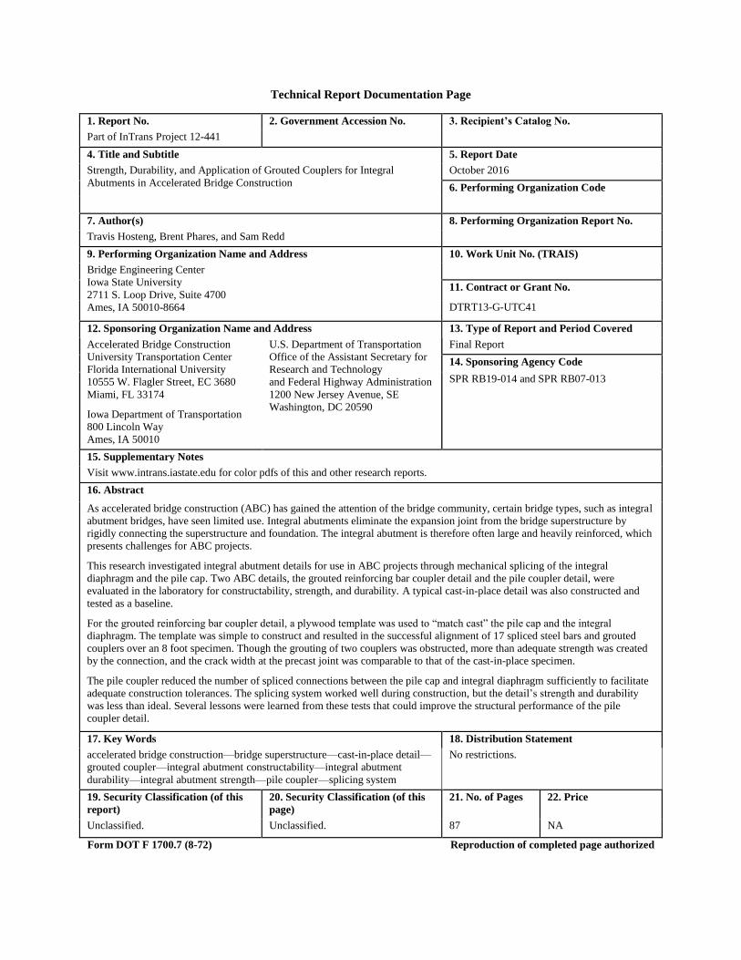
with a slide-in bridge application, and is shown conceptually in Figure 15.
19
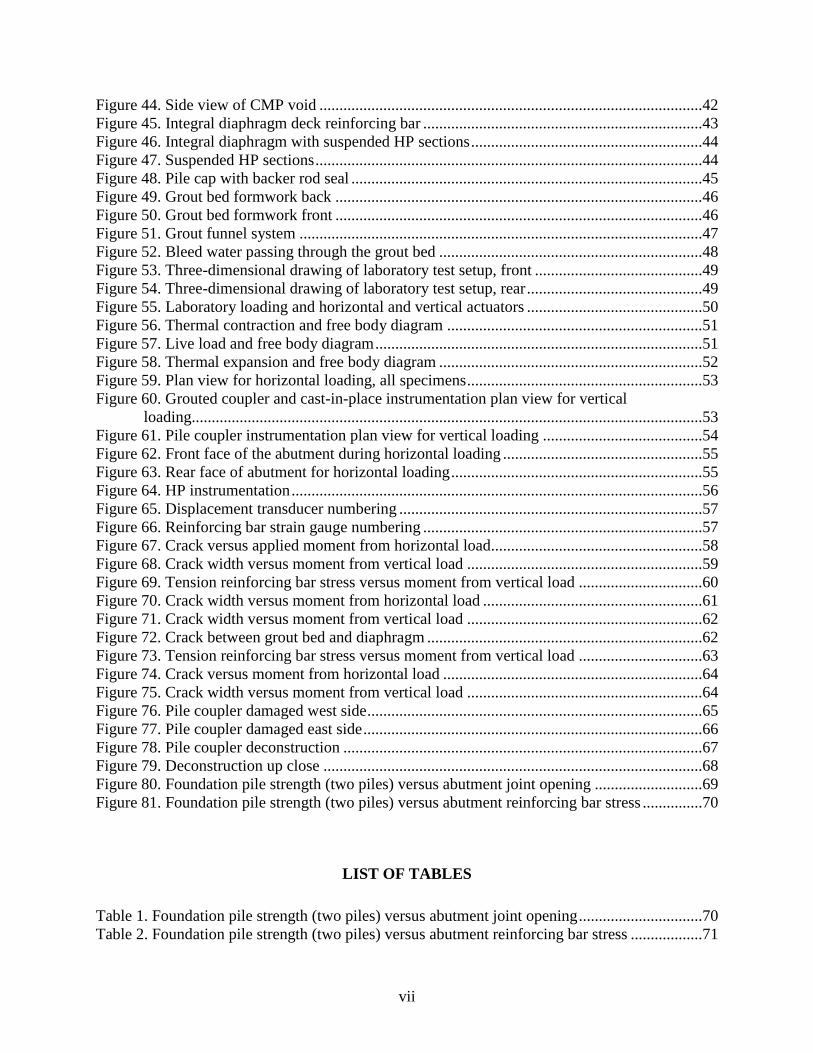
Figure 15. Slide-in bridge using pile couplers
The pile coupler design aims to minimize the number of mechanical connections between the
integral diaphragm and pile cap to facilitate the use of slide-in-bridge construction. The pile
coupler design uses a 2 foot length of H-pile (HP) section and a 24 inch diameter CMP to
essentially create a large grouted coupler that splices the integral diaphragm and pile cap. The
resulting detail and dimensions of the laboratory specimen are illustrated in plan view in Figure
16 and in subsequent section views in Figures 17, 18 and 19.
Figure 16. Plan view pile coupler
20
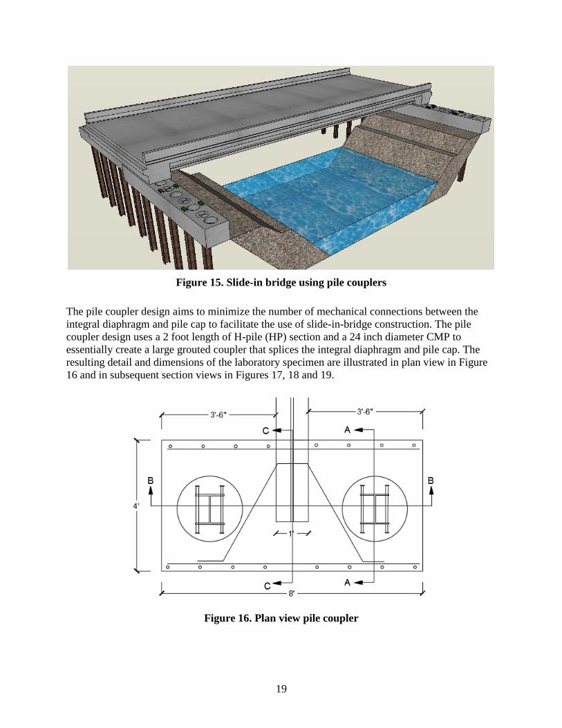
Figure 17. Section view A - pile coupler
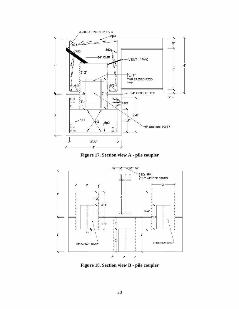
Figure 18. Section view B - pile coupler
21
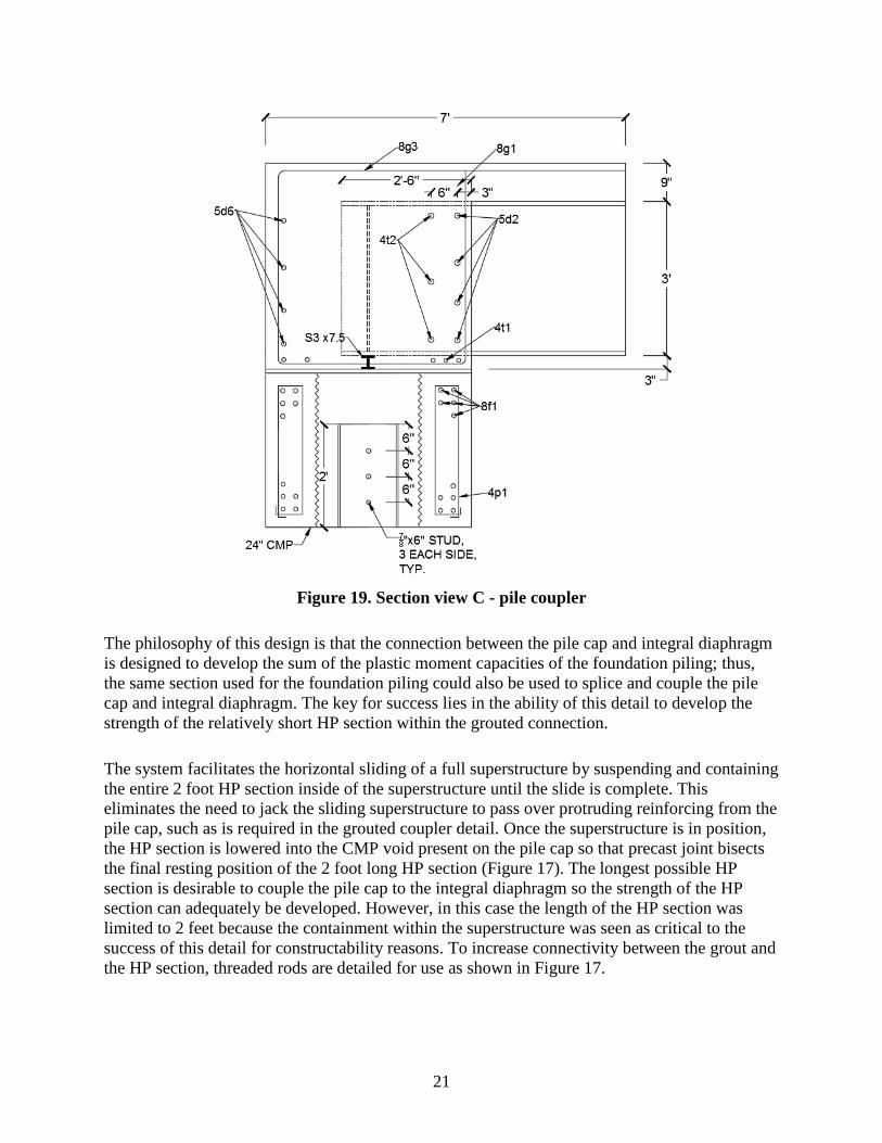
Figure 19. Section view C - pile coupler
The philosophy of this design is that the connection between the pile cap and integral diaphragm
is designed to develop the sum of the plastic moment capacities of the foundation piling; thus,
the same section used for the foundation piling could also be used to splice and couple the pile
cap and integral diaphragm. The key for success lies in the ability of this detail to develop the
strength of the relatively short HP section within the grouted connection.
The system facilitates the horizontal sliding of a full superstructure by suspending and containing
the entire 2 foot HP section inside of the superstructure until the slide is complete. This
eliminates the need to jack the sliding superstructure to pass over protruding reinforcing from the
pile cap, such as is required in the grouted coupler detail. Once the superstructure is in position,
the HP section is lowered into the CMP void present on the pile cap so that precast joint bisects
the final resting position of the 2 foot long HP section (Figure 17). The longest possible HP
section is desirable to couple the pile cap to the integral diaphragm so the strength of the HP
section can adequately be developed. However, in this case the length of the HP section was
limited to 2 feet because the containment within the superstructure was seen as critical to the
success of this detail for constructability reasons. To increase connectivity between the grout and
the HP section, threaded rods are detailed for use as shown in Figure 17.

22
Prior to grouting and casting the integral diaphragm, a steel cable is attached to the HP section
and strung through a hook on the CMP lid and out of the 1 inch vent. This allows workers to
suspend and lower the HP section within the CMP void in the abutment. In order to guide and
prevent the HP sections from rotating out of strong axis bending, reinforcing steel is welded to
the lid of the CMP and fits in the four corners of the web and flanges of the HP section. In order
to grout the CMP void once the HP section is lowered into place, a 3 inch diameter PVC pipe is
cast into the diaphragm at an angle so that grout can be gravity fed (Figure 17). A 1 inch PVC
pipe is also cast into the diaphragm and doubles as an air vent and as a way to suspend and lower
the pile (Figure 17). The vent pipe is tilted upwards slightly so the CMP void fills entirely with
grout, pushing out all the air inside, before the grout begins to exit out of the PVC vent. At this
time, the vent is plugged and grout is poured until the 3 inch PVC vent is completely filled.
During the design of this detail, there was talk amongst the research team and TAC of extending
the CMP void to the top of the concrete deck. This would eliminate the suspension of the HP
section and allow for the use of longer HP sections because they could be placed into the voids
once the bridge superstructure is slid in place. The subsequent grouting process would also be
easier because access to the voids would be from the top of the bridge deck. Despite these
advantages, this route was ultimately not chosen in order to avoid the resulting construction joint
on the bridge deck, where the use of de-icing salts is heavy during the winter months. The
infiltration of chlorides at construction joints on ABC projects has been observed, and the
resulting effect on long-term durability is unknown. Subsequently, partial-depth voids within the
integral diaphragm and pile cap were selected to avoid a construction joint on the bridge deck, a
decision that was seen as critical to the long-term success of this detail.
23
CHAPTER 4. CONSTRUCTION
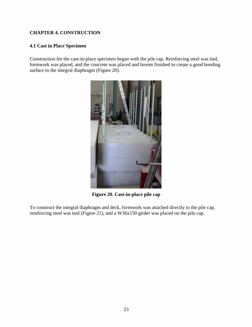
4.1 Cast in Place Specimen
Construction for the cast-in-place specimen began with the pile cap. Reinforcing steel was tied,
formwork was placed, and the concrete was placed and broom finished to create a good bonding
surface to the integral diaphragm (Figure 20).
Figure 20. Cast-in-place pile cap
To construct the integral diaphragm and deck, formwork was attached directly to the pile cap,
reinforcing steel was tied (Figure 21), and a W36x150 girder was placed on the pile cap.

24
Figure 21. Cast-in-place integral diaphragm
Epoxy-coated bars were used for the vertical bars that connect the pile cap to the diaphragm.
Black bar was used in the remainder of the abutment because the slip between the concrete and
reinforcing steel was not seen as critical to the evaluation and performance of the detail in this
study. The diaphragm and 3 feet of deck were cast monolithically, which is consistent with
construction practices in the field. Figure 22 shows the completed cast-in-place specimen in
addition to the reaction blocks used for rigidly connecting the specimen to the floor.

25
Figure 22. Cast-in-place integral abutment specimen
4.2 Grouted Reinforcing Bar Coupler Specimen
To construct the grouted reinforcing bar coupler specimen, the pile cap was fabricated very
similarly to the cast-in-place specimen, taking extra time to precisely place the vertical bars that
connect the pile cap to the diaphragm. Since these bars were being spliced with grouted
reinforcing bar couplers, it was important that these bars be plumb and in the correct location,
facilitating a proper fit later. However, maintaining exact placement of the vertical bars was
impractical because the bars continually shifted while tying the reinforcing steel cage and during
the concrete pour (Figure 23).

26
Figure 23. Pile cap reinforcing bar, formwork, and pour
After casting, all of the vertical reinforcing steel was within 1/2 inch of the planned locations and
relatively plumb (Figure 24).
Figure 24. Grouted coupler pile cap
Using a cheater bar, the reinforcing steel bars that had shifted during the pour were bent to the
vertical position. To ensure that the couplers would be properly aligned with the protruding
reinforcing steel in the pile cap after casting the diaphragm, a template was created to “match

27
cast” the specimens. The template (Figure 25) was a 4 by 8 foot sheet of plywood that was laid
over the top of the pile cap reinforcing steel so that the exact locations could be marked and then
drilled into the template.
Figure 25. Grouted coupler template
Form plugs (Figure 26) were then installed into the holes on the template and tightened to hold
the grouted coupler tight to the template.

28
Figure 26. Form plug
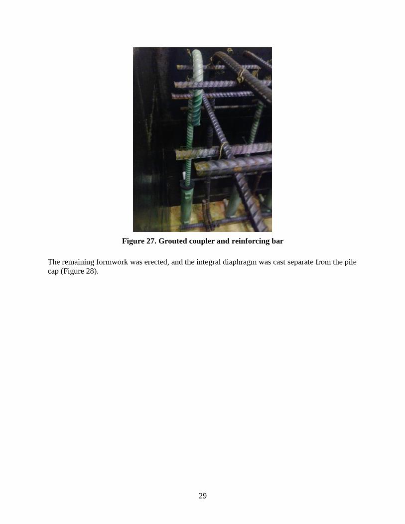
With the template complete and the grouted couplers in place, the template served as the base for
the formwork, and the remainder of the reinforcing steel was tied and the steel girder was moved
into place (Figure 27).
29
Figure 27. Grouted coupler and reinforcing bar
The remaining formwork was erected, and the integral diaphragm was cast separate from the pile
cap (Figure 28).

30
Figure 28. Integral diaphragm and deck, formwork, and reinforcing bar
With construction of the integral diaphragm complete (Figure 29), a trial fit of the pile cap and
diaphragm was made to ensure that the 17 reinforcing steel bars and grouted couplers aligned.

31
Figure 29. Integral diaphragm
With proper alignment confirmed, 1/2 inch steel shims were placed on the pile cap to support the
integral diaphragm during placement of the grout bed. To ensure that the bedding grout did not
infiltrate the reinforcing bar couplers, seal plugs were placed on the protruding reinforcing steel
bars (Figures 30 and 31).

32
Figure 30. Seal plug
Figure 31. Neoprene disk, seal plug, and shim
Next, the surfaces of the precast joint were wetted to the saturated surface dry condition (Figure
32), and formwork was installed to cover and seal the precast joint (Figure 33) in preparation for
pumping the grout bed.

33
Figure 32. Integral diaphragm placement
Figure 33. Grout bed formwork

34
Three holes were cut on the front and back of the grout bed formwork, as well as one hole on
either side, so that grout could be pumped into the precast joint from multiple locations. Starting
at one corner of the specimen, grout was pumped via a hand pump (Figure 34) until clean grout
started coming out of the hole on the opposite side of the specimen.
Figure 34. Grout hand pump
This process was repeated, alternating back and forth from the front to the back side of the
specimen, until no more grout could be pumped into any of the holes, with individual holes being
plugged as soon as it appeared that the area was adequately filled with grout. Removal of the
formwork and inspection of the perimeter of the joint indicated that the grout had adequately
filled the bedding joint (Figure 35).

35
Figure 35. Completed grout bed and coupler grouting
However, without opening up the joint completely it was not possible to know the adequacy of
the grout coverage across the entire bedding area. Rough calculations were performed to
determine the amount of grout required to fill the joint; this number closely matched the quantity
of grout pumped into the joint, giving confidence that the entire joint, or a large amount of the
joint, had been filled.
In preparation for grouting the reinforcing bar couplers, air was blown into each grouted coupler
to clean the coupler of any dust and check that the top and bottom ports were unobstructed. Two
of the grouted couplers did not pass the air test, as grout from the bed seeped past the seal plug
and partially filled the couplers, thus blocking fill from the lower port. The grouted couplers
labeled 2 and 17 in Figure 36 were blocked.

36
Figure 36. Grouted coupler layout
To grout the functioning couplers, grout was mixed one bag at a time, according to manufacturer
recommendations, and poured into the hand pump. The nozzle of the hand pump was then placed
into the bottom port of a grouted coupler, and grout was pumped until clean grout flowed out of
the top port. The top port was then immediately plugged, and care was taken to quickly remove
the nozzle at the bottom port and plug the port as quickly as possible. This is the process outlined
and recommended by the reinforcing bar coupler manufacturer.
Overall, the grouted coupler specimen took more time and effort to construct than the traditional
cast-in-place specimen. Most of the extra time was in the alignment of the spliced vertical bars in
the pile cap. Fortunately, the template for the grouted couplers worked well and facilitated a
successful fit for the precast element connection. Even though the precast elements were more
challenging to construct, the crucial aspect for ABC projects is the erection time. Placing the
precast element and grout bed formwork and grouting the bed and finally the couplers was a fast
process and could be replicated in the field, facilitating a quick erection of the bridge. A
contractor should pay special attention to sealing the bottom of the grouted couplers during
placement of the grout bed so grout does not leak into the couplers and block the grouting
operation, as it did in this investigation.
4.3 Pile Coupler Specimen
To construct the pile coupler specimen, the reinforcing steel cage for the pile cap was tied with 3
inch PVC pipes fitted at the bottom of the cage, which were used to post-tension the pile cap to
the floor for testing (Figure 37).

37
Figure 37. Pile cap reinforcing steel bar cage
Formwork was erected around the cage, and a CMP was used to create a void in the pile cap for
the HP section (Figure 38).

38
Figure 38. Pile cap reinforcing bar, formwork, and CMP
To seal the bottom of the CMP and create the void, plywood was cut into two half-circles and
placed in the bottom of the CMP, which facilitated easy removal of the plywood after concrete
placement (Figure 39).
Figure 39. CMP void in pile cap
To create the void in the integral diaphragm, a circular piece of sheet metal, 3/16 inch thick, was
fabricated and used as a lid for the CMP. The thickness of the lid was chosen so that minimal
deflection, less than 1/2 inch, would occur due to the concrete pressure present on the lid during

39
the pour. A U-shaped anchor bolt was installed in the center of the CMP lid, which, in
combination with a steel cable, functioned as a pulley for suspending and lowering the HP
section inside of the integral diaphragm. Holes were drilled in the steel lid and #4 reinforcing
steel bars were welded in the holes, creating a guide system for lowering the HP section (Figure
40).
Figure 40. CMP lid with reinforcing bar guides and U-bolt
To attach the lid to the CMP, three holes 1/8 inches in diameter were drilled, and tie wire was
used to secure the two together (Figure 41).

40
Figure 41. CMP with lid
Holes were drilled in the HP section, and threaded rods and nuts were installed in lieu of shear
studs (Figure 42).
Figure 42. HP section with threaded rods

41
Once the integral diaphragm reinforcing steel bars were tied, the CMP voids were placed inside
the cage (Figure 43).
Figure 43. Integral diaphragm reinforcing bar cage
A 3 inch PVC duct with a flange was attached to the CMP lid and run to the back side of the
abutment formwork. The flange on the 3 inch PVC allowed for the CMP void to be filled all the
way to the top before grout started filling the 3 inch PVC pipe. A 1 inch hole was also drilled in
the CMP for a 3/4 inch PVC pipe that functioned as a vent and gave access to the pulley system
(Figure 44).

42
Figure 44. Side view of CMP void
A steel cable was attached to the HP section and run through the U-bolt on the CMP lid and
through the 3/4 inch PVC pipe, where it remained during the casting of the integral diaphragm,
and was retrieved after the formwork was removed. With the HP section and CMP void in place,
the integral diaphragm was ready to be cast (Figure 45).

43
Figure 45. Integral diaphragm deck reinforcing bar
Once the concrete had been placed, finished, and cured, the formwork was removed and the steel
cables connected to the HP sections were pulled tight. This suspended the HP sections for
transportation of the integral diaphragm (Figures. 46 and 47).

44
Figure 46. Integral diaphragm with suspended HP sections
Figure 47. Suspended HP sections
Washer plates and clamps were used to hold the cable tight during the transportation and
placement of the superstructure.

45
Prior to placement of the diaphragm on top of the pier cap, 1.5 inch foam backer rod was placed
around the CMP on the pile cap (Figure 48) to create a dam around the CMP void.
Figure 48. Pile cap with backer rod seal
This was principally done in order to prevent grout bed material from filling the CMP void. The
backer rod also alleviated inaccuracies in placement of the CMP voids, as the top and bottom
CMP were not perfectly aligned. The surface of the precast joint was then wetted to the saturated
surface dry condition before the diaphragm was lowered onto the pile cap. Once the integral
diaphragm was in place, the metal clamps were taken off of the steel cable holding up the HP
sections, and the piles were lowered. In the laboratory, several checks were made prior to the
final install to ensure and confirm the proper function of the pile lowering system. To place the
grout bed, formwork was installed over the precast joint and the grout bed was pumped into
place using the technique utilized in the construction of the grouted coupler specimen (Figures
49 and 50).
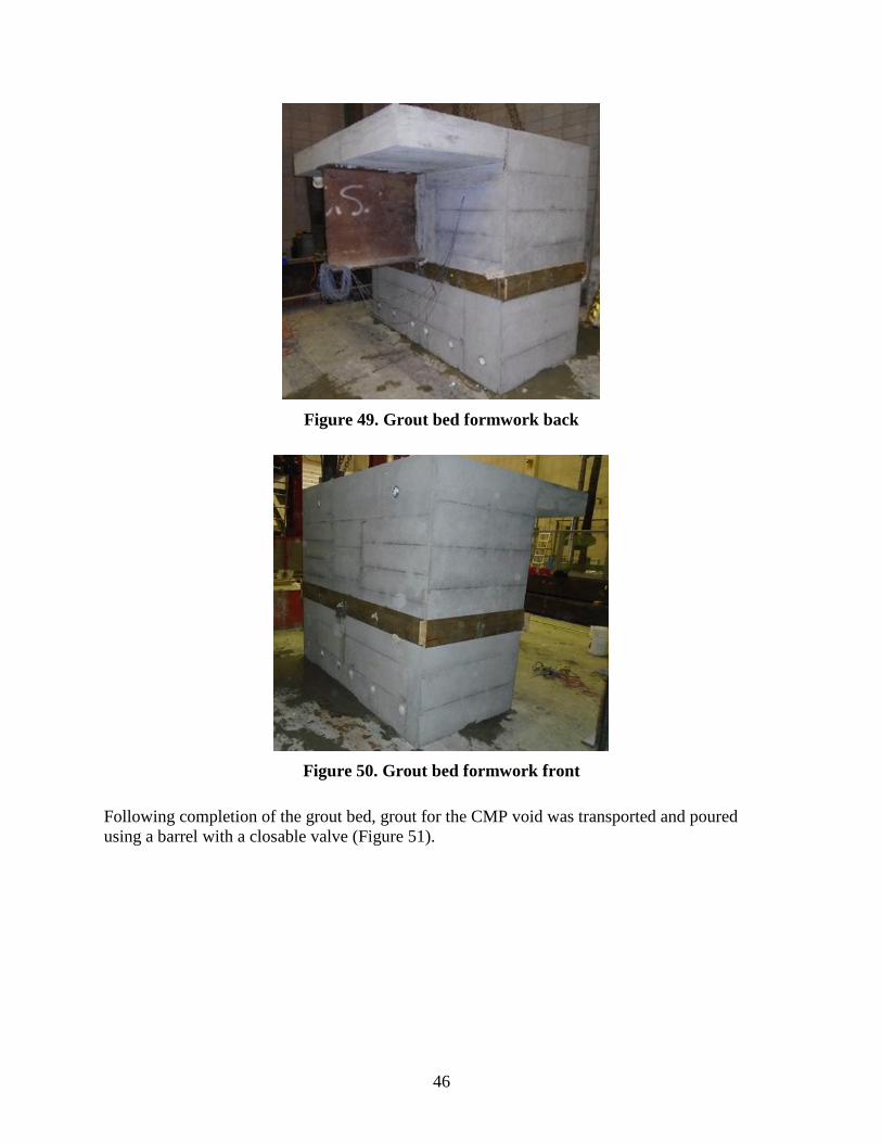
46
Figure 49. Grout bed formwork back
Figure 50. Grout bed formwork front
Following completion of the grout bed, grout for the CMP void was transported and poured
using a barrel with a closable valve (Figure 51).
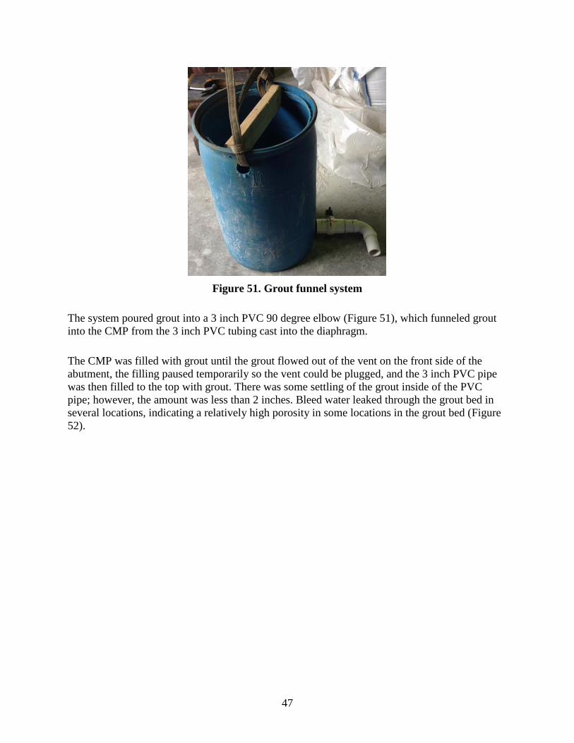
47
Figure 51. Grout funnel system
The system poured grout into a 3 inch PVC 90 degree elbow (Figure 51), which funneled grout
into the CMP from the 3 inch PVC tubing cast into the diaphragm.
The CMP was filled with grout until the grout flowed out of the vent on the front side of the
abutment, the filling paused temporarily so the vent could be plugged, and the 3 inch PVC pipe
was then filled to the top with grout. There was some settling of the grout inside of the PVC
pipe; however, the amount was less than 2 inches. Bleed water leaked through the grout bed in
several locations, indicating a relatively high porosity in some locations in the grout bed (Figure
52).
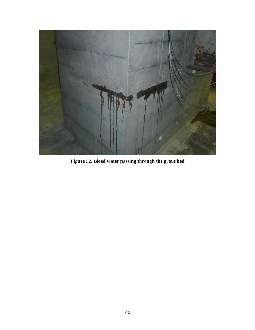
48
Figure 52. Bleed water passing through the grout bed
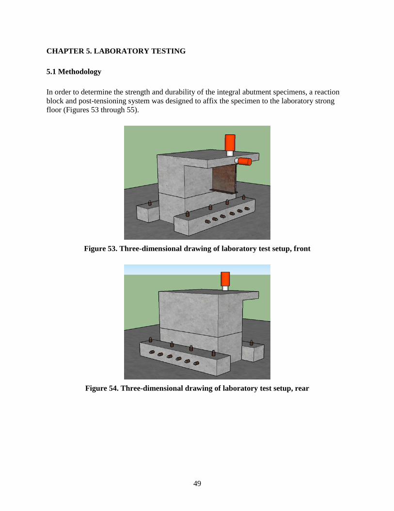
49
CHAPTER 5. LABORATORY TESTING
5.1 Methodology
In order to determine the strength and durability of the integral abutment specimens, a reaction
block and post-tensioning system was designed to affix the specimen to the laboratory strong
floor (Figures 53 through 55).
Figure 53. Three-dimensional drawing of laboratory test setup, front
Figure 54. Three-dimensional drawing of laboratory test setup, rear
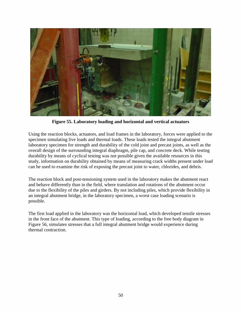
50
Figure 55. Laboratory loading and horizontal and vertical actuators
Using the reaction blocks, actuators, and load frames in the laboratory, forces were applied to the
specimen simulating live loads and thermal loads. These loads tested the integral abutment
laboratory specimen for strength and durability of the cold joint and precast joints, as well as the
overall design of the surrounding integral diaphragm, pile cap, and concrete deck. While testing
durability by means of cyclical testing was not possible given the available resources in this
study, information on durability obtained by means of measuring crack widths present under load
can be used to examine the risk of exposing the precast joint to water, chlorides, and debris.
The reaction block and post-tensioning system used in the laboratory makes the abutment react
and behave differently than in the field, where translation and rotations of the abutment occur
due to the flexibility of the piles and girders. By not including piles, which provide flexibility in
an integral abutment bridge, in the laboratory specimen, a worst case loading scenario is
possible.
The first load applied in the laboratory was the horizontal load, which developed tensile stresses
in the front face of the abutment. This type of loading, according to the free body diagram in
Figure 56, simulates stresses that a full integral abutment bridge would experience during
thermal contraction.

51
Figure 56. Thermal contraction and free body diagram
The horizontal load chosen to be applied in the laboratory was 100 kips. This load was chosen
after examining the thermal forces that could be resisted by the stiffness of the foundation piling
and surrounding soil. The intent of the horizontal load is not to fail the specimen, but rather to
obtain expectations in performance of the abutment under service loading.
The second load applied in the laboratory was the vertical load. This type of loading developed
tension in the back face of the abutment, which, according to the free body diagrams in Figures
57 and 58, is the same type of stress developed in a full integral abutment bridge during live
loading and thermal expansion.
Figure 57. Live load and free body diagram

52
Figure 58. Thermal expansion and free body diagram
The intent of this loading is to first examine the durability of the precast/cold joint through
measuring the crack width that develops under the service loading condition. The vertical load in
the laboratory was capable of applying a force of 400 kips, which is an applied moment of 2,000
kip-ft, measured from the load to the center of the abutment. This load significantly exceeds the
stresses that are expected to be developed in the service loading condition and the maximum
possible stresses that can be developed given the relative strength of the foundation piling. In
addition, this loading scenario was utilized in the prediction of the failure mechanism of the
integral abutment detail. The resulting information can be used to determine an accurate factor of
safety in the details, as well as a range in the types of foundation piling that can be used in
conjunction with the detail.
5.2 Instrumentation
To measure the durability of the specimens, the cold/precast joint between the pile cap and
integral diaphragm was instrumented with displacement transducers. The displacement
transducers were placed on the front side of the abutment during the horizontal loading and on
the back face of the abutment during the vertical loading. The transducers measured the width of
the crack that developed on the tension face of the abutment in order to compare this information
for the various specimens. Additional displacement transducers were placed on the rear side of
the abutment during horizontal loading to measure the horizontal slip between the pile cap and
integral diaphragm. The locations of the vertical displacement transducers are represented by
squares and the horizontal displacement transducers are represented by pentagons in Figures 59,
60, and 61 for the different specimens and loading cases.

53
Figure 59. Plan view for horizontal loading, all specimens
Figure 60. Grouted coupler and cast-in-place instrumentation plan view for vertical
loading

54
Figure 61. Pile coupler instrumentation plan view for vertical loading
Images of the typical instrumentation setup are shown for the horizontal loading test in Figures
62 and 63.

55
Figure 62. Front face of the abutment during horizontal loading
Figure 63. Rear face of abutment for horizontal loading
To measure the strength of the specimens, strain transducers were placed on the tension and
compression faces of the abutment 2 inches below the joint. The locations of these gauges on the
specimen for the different loading cases are illustrated in Figures 59, 60, and 61. The gauges are
also pictured in the horizontal loading test in Figures 62 and 63. On the vertical “8g1” steel
Displacement transducer Strain gauge
Strain
gauge
Displacement transducer

56
reinforcing bars that connect the pile cap to the integral diaphragm, sacrificial strain gauges were
installed on the bars prior to casting the specimen. Two strain gauges were placed on each steel
reinforcing bar, one 4 inches below the joint and the second 18 inches above the joint, which was
directly above the grouted couplers. To measure the development in strength of the HP section
used to splice the pile coupler specimen, three strain gauges were placed on each flange as
shown in Figure 64.
Figure 64. HP instrumentation
The use of the concrete and reinforcing steel strain gauges allows study of the failure
mechanisms of the abutments tested. This information allows for the strength of the ABC
specimens and the standard integral abutment design to be compared as well as allows for
comment on the relative strengh of the abutment in comparison to the foundation piling.
Additional displacement instrumentation using string pods to measure the displacements between
the specimen and the laboratory floor was used. This instrumentation was used to evaluate the tie
down system used to restrain the specimen by measuring the slip and calculating the rotation of
the specimen. In the examination of this information, no significant rotations or slip were found
to have occurred during the testing of any of the three specimens.
5.3 Results
To summarize the results from the instrumentation placed on the laboratory specimen, a
numbering system was created as shown in Figures 65 and 66.

57
Figure 65. Displacement transducer numbering
Figure 66. Reinforcing bar strain gauge numbering
The displacement transducers that measured the crack width were numbered. This numbering
was used for both the vertical and horizontal testing, where the transducers were on the tension
side of the abutment. In Figure 66, the strain gauges present on the vertical reinforcing steel in
the cast-in-place and grouted reinforcing bar coupler specimen have been labeled as well.

58
5.3.1 Cast in Place
First, a horizontal load of 100 kips was applied to the cast-in-place specimen. This loading
resulted in no significant signs of distress; only a minor crack that opened at the cold joint
measuring 0.001 inches wide was observed. In Figure 67, the width of the crack that developed
between the pile cap and diaphragm at various locations is plotted against the applied moment.
Figure 67. Crack versus applied moment from horizontal load
The applied moment is calculated by multiplying the load by the vertical distance from the load
to the joint between the pile cap and diaphragm. The cast-in-place specimen had a maximum
crack opening of 0.001 inches at an applied moment of approximately 310 ft-k and experienced
no horizontal slip between the pile cap and integral diaphragm during the test.
Next, the vertical load was applied up to approximately 385 kips. The specimen showed no
visible signs of distress at this point other than the crack that developed at the cold joint, which
reached a maximum width of 0.025 inches at a peak moment of approximately 1,800 ft-k. The
crack width versus applied moment is plotted in Figure 68, where the moment is calculated by
multiplying the load by the horizontal distance to the center of the integral diaphragm/pile cap.
0.0000
0.0002
0.0004
0.0006
0.0008
0.0010
0.0012
0.0 50.0 100.0 150.0 200.0 250.0 300.0 350.0
Cra
ck (
in.)
Moment (ft-k)
DCDT 1
DCDT 2
DCDT 3
DCDT 4
DCDT 6
DCDT 5
DCDT 7

59
Figure 68. Crack width versus moment from vertical load
The maximum stress measured in the vertical reinforcing steel connecting the pile cap to the
diaphragm was 42 ksi. Since the specimen was still in the linear elastic range, the reinforcing
steel would not have yielded until an applied vertical load of 550 kips, corresponding to an
applied moment of 2,590 ft-k (Figure 69). According to the strain measurements in the concrete,
the failure would have been ductile in accordance with AASHTO LRFD Bridge Design
Specifications (AASHTO 2012). The strains recorded in the strain gauge located 18 inches above
the construction joint were low, as the section remained uncracked at this location throughout the
testing.
0.000
0.005
0.010
0.015
0.020
0.025
0.030
0 500 1000 1500 2000
Cra
ck (
in.)
Moment (ft-k)
DCDT 1
DCDT 2
DCDT 3
DCDT 4
DCDT 5
DCDT 6
DCDT 7

60
Figure 69. Tension reinforcing bar stress versus moment from vertical load
5.3.2 Grouted Reinforcing Bar Coupler
The grouted reinforcing bar coupler specimen was loaded horizontally up to 100 kips, at which
point the maximum crack width on the front side of the specimen was 0.001 inches (Figure 70),
which indicates a performance nearly identical to that of the cast-in-place specimen (0.001
inches).
0
5
10
15
20
25
30
35
40
45
0 500 1000 1500 2000
Reb
ar S
trai
n (
ksi)
Moment (ft-k)
Tension 1
Tension 2
Tension 3

61
Figure 70. Crack width versus moment from horizontal load
Again, no horizontal slip was measured between the pile cap and the integral diaphragm. The
vertical load placed on the specimen peaked at 338 kips, at which point the reaction frame used
on this specimen unexpectedly reached capacity, resulting in a maximum applied moment of
1,550 ft-k. The maximum crack width versus applied moment for the vertical loading is shown in
Figure 71, which shows a maximum value of 0.035 inches. The crack is pictured in Figure 72.
0.000
0.001
0.002
0.003
0.004
0.005
0.006
0.007
0.008
0.009
0 50 100 150 200 250 300 350
Cra
ck (
in.)
Moment (ft-k)
DCDT 1
DCDT 2
DCDT 3
DCDT 4
DCDT 5
DCDT 6
DCDT 7

62
Figure 71. Crack width versus moment from vertical load
Figure 72. Crack between grout bed and diaphragm
This value was larger than the crack that developed on the cast-in-place specimen, having a value
of 0.020 inches measured at the same applied moment of 1,550 ft-k.
0
0.005
0.01
0.015
0.02
0.025
0.03
0.035
0.04
0.045
0.05
0 200 400 600 800 1000 1200 1400 1600 1800
Cra
ck (
in.)
Moment (ft-k)
DCDT 1
DCDT 2
DCDT 4
DCDT 5
DCDT 6
DCDT 7
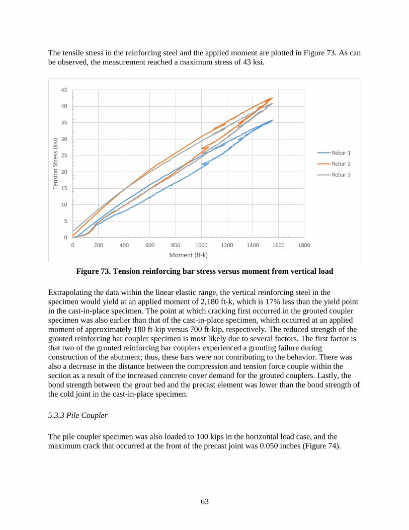
63
The tensile stress in the reinforcing steel and the applied moment are plotted in Figure 73. As can
be observed, the measurement reached a maximum stress of 43 ksi.
Figure 73. Tension reinforcing bar stress versus moment from vertical load
Extrapolating the data within the linear elastic range, the vertical reinforcing steel in the
specimen would yield at an applied moment of 2,180 ft-k, which is 17% less than the yield point
in the cast-in-place specimen. The point at which cracking first occurred in the grouted coupler
specimen was also earlier than that of the cast-in-place specimen, which occurred at an applied
moment of approximately 180 ft-kip versus 700 ft-kip, respectively. The reduced strength of the
grouted reinforcing bar coupler specimen is most likely due to several factors. The first factor is
that two of the grouted reinforcing bar couplers experienced a grouting failure during
construction of the abutment; thus, these bars were not contributing to the behavior. There was
also a decrease in the distance between the compression and tension force couple within the
section as a result of the increased concrete cover demand for the grouted couplers. Lastly, the
bond strength between the grout bed and the precast element was lower than the bond strength of
the cold joint in the cast-in-place specimen.
5.3.3 Pile Coupler
The pile coupler specimen was also loaded to 100 kips in the horizontal load case, and the
maximum crack that occurred at the front of the precast joint was 0.050 inches (Figure 74).
0
5
10
15
20
25
30
35
40
45
0 200 400 600 800 1000 1200 1400 1600 1800
Ten
sio
n S
tres
s (k
si)
Moment (ft-k)
Rebar 1
Rebar 2
Rebar 3

64
Figure 74. Crack versus moment from horizontal load
This crack width is significantly greater than the crack width measured in the cast-in-place
specimen of 0.0011 inches. The vertical loading of this specimen reached the ultimate strength of
the detail at an applied moment of 1,124 ft-k (Figure 75).
Figure 75. Crack width versus moment from vertical load
0.00
0.01
0.02
0.03
0.04
0.05
0.06
0 50 100 150 200 250 300 350
Cra
ck (
in.)
Moment (ft-k)
DCDT 1
DCDT 2
DCDT 3
DCDT 5
DCDT 6
DCDT 7
0.00
0.20
0.40
0.60
0.80
1.00
1.20
1.40
0 200 400 600 800 1000 1200
Cra
ck (
in.)
Moment (ft-k)
DCDT 1
DCDT 2
DCDT 3
DCDT 4
DCDT 5
DCDT 6
DCDT 7

65
The joint opening on the rear face of the specimen became so large that the displacement
transducers were out of range. At the ultimate load applied to the specimen, the crack width
between the pile cap and integral diaphragm was measured to be 1.75 inches.
Cracking in the integral diaphragm became prominent at an applied bending moment of
approximately 800 ft-kips and is shown at the maximum load applied in Figures 76 and 77.
Figure 76. Pile coupler damaged west side

66
Figure 77. Pile coupler damaged east side
The vertical crack on the integral diaphragm is at the centerline of the CMP, and the horizontal
cracks correspond to the top and bottom of the CMP used to create the pile coupler voids in the
pile cap and diaphragm.
Most likely some amount of slip occurring between the HP section and the grout, as well as
between the CMP and the grout/concrete, allowed for the initial crack between the pile cap and
integral diaphragm to develop. Once the concrete in the integral diaphragm began to crack,
which occurred at around 800 ft-k (Figure 75), the opening at the precast joint began to
significantly increase. At this point, large amounts of rotation and cracking began to develop
within the abutment until ultimate failure occurred.

67
The maximum stress captured by the gauges attached to the HP section was 26 ksi, indicating
that yielding of the HP section was likely not a failure mechanism of the detail. The failure
mechanism between the pile coupler/CMP/concrete within the detail is unknown. An attempt
was made to jackhammer through the cracked concrete to investigate the failure mechanism;
however, no definitive conclusions could be made. Jackhammering exposed the CMP (Figures
78 and 79) and showed that slip had occurred between the CMP and the concrete in the
diaphragm, as well as that the grout had failed in tension within the CMP.
Figure 78. Pile coupler deconstruction

68
Figure 79. Deconstruction up close
Examining the image in Figure 77, deformation within the integral diaphragm is noticeable as a
result of the large crack that developed within the section.
This reveals that a less than ideal amount or distribution of reinforcing steel was present within
the abutment to resist the tension stresses developed by the pile coupler mechanism.
5.3.4 Foundation Pile Strength
To design an integral abutment, the connection between the pile cap and the integral diaphragm
is designed to be stronger in shear and flexure than the driven foundation piling. Thus, the plastic
moment capacity of the foundation piling limits the flexural stresses that can be developed in the
abutment. This laboratory investigation did not include foundation piles in the testing; however,
it is important to understand the performance of the abutment relative to the system in which it
will be used in the field. In Figures 80 and Figure 81, the plastic moment capacity of two
foundation H-pile sections of various sizes are plotted along the x-axis, which represents the
applied moment.

69
Figure 80. Foundation pile strength (two piles) versus abutment joint opening
0.00
0.02
0.04
0.06
0.08
0.10
0.12
0.14
0.16
0.18
0.20
0.22
0 200 400 600 800 1000 1200 1400 1600 1800 2000
Join
t o
pen
ing
(in
.)
Moment (k-ft)
Pile Coupler Grouted Rebar Coupler CIP
HP14x117 Weak Axis
HP 10x57 Strong Axis
HP 10x57 Weak Axis
HP 14x108 Strong Axis

70
Figure 81. Foundation pile strength (two piles) versus abutment reinforcing bar stress
Along the y-axis in Figure 80, and in the accompanying Table 1, the crack width at the
cold/precast joints in all three specimens were plotted to illustrate durability as a measurement of
the joint opening.
Table 1. Foundation pile strength (two piles) versus abutment joint opening
Specimen
Joint opening at pile yield (inches)
HP 10x57
weak axis
(252 ft-k)
HP 10x57
strong axis
(554 ft-k)
HP 14x117
weak axis
(762 ft-k)
HP 14x102
strong axis
(1408 ft-k)
Cast-in-place 0.000 0.001 0.003 0.015
Grouted reinforcing bar coupler 0.004 0.011 0.016 0.035
Pile coupler 0.028 0.069 0.127 N/A
In Figure 81 and in the accompanying Table 2, the tensile stress in the center reinforcing steel is
plotted along the y-axis to illustrate the strength of the detail.
0
5
10
15
20
25
30
35
40
45
0 200 400 600 800 1000 1200 1400 1600 1800 2000
Reb
ar T
ensi
le S
tres
s (k
si)
Moment (ft-k)
Grouted Rebar Coupler Cast-in-place
HP14x117
Weak Axis
HP 10x57
Strong Axis
HP 10x57
Weak Axis
HP 14x108
Strong Axis

71
Table 2. Foundation pile strength (two piles) versus abutment reinforcing bar stress
Specimen
Stress in reinforcing bar (ksi)
HP 10x57
weak axis
(252 ft-k)
HP 10x57
strong axis
(554 ft-k)
HP 14x117
weak axis
(762 ft-k)
HP 14x102
strong axis
(1408 ft-k)
Cast-in-place 0.1 2.1 4.4 27.9
Grouted reinforcing bar coupler 6.4 13.6 18.8 37.9
The plastic moment capacity for two piles is plotted because the laboratory specimen was 8 feet
in width and a pile spacing of 4 feet was chosen to make this comparison.
The crack width of the cold/precast joints for the cast-in-place specimen and grouted coupler
specimen were both relatively low in magnitude. The grouted reinforcing bar coupler detail
experienced a wider crack width than the cast-in-place specimen due to several factors, including
bond strength between the grout bed and precast element, incomplete grouting of two couplers,
and increased concrete cover for the reinforcing steel. Engineering judgment is required to
determine tolerable crack widths in concrete structures based on many factors. These factors are
climate, soil type, length of the bridge, and type of foundation pile, all of which vary greatly
from agency to agency. Examining these factors will play a role in the engineering judgment
used to select joint protection, amount of concrete cover, and type of corrosion-resistant bar in
order to establish a service life for the structure. Additionally, the crack widths presented in this
report are after one loading of the abutment. These values are expected to increase over many
cycles of loading and as deterioration starts to occur.
While the strength of the grouted reinforcing bar coupler specimen was also slightly less than
that of the cast-in-place specimen, it is clear that both details satisfy the design philosophies
stated in this report. The relative strength of the cast-in-place specimen and grouted reinforcing
bar coupler detail in comparison to the foundation piling suggest that a smaller abutment could
be used to satisfy the design. This reduction in weight or number of spliced connections is
advantageous to the constructability of the detail, which is often a driving factor in ABC. Further
investigations and calculations, which will likely vary greatly based on the individual needs of a
particular agency, are needed to support this claim. However, a reduction in the overall strength
of the design will likely increase the crack width between the pile cap and integral diaphragm,
which may already be governing the design.

72
CHAPTER 7. SUMMARY
Integral abutments have rarely been used in ABC because they are often large and heavy and
have complex reinforcing details. These aspects make the integral abutment difficult to precast
because of weight and construction tolerances. As a result, integral abutments constructed for
ABC projects have typically relied on cast-in-place closure pours. However, there are certain
benefits to precasting the abutment, as material closure pours add significant cost to the project
and add curing time to the project schedule.
In order to investigate precast integral abutments, two details were designed, constructed, and
tested in the structures laboratory. The two ABC details investigated in this research spliced the
integral abutment at the typical construction joint between the pile cap and integral diaphragm.
The first detail, called the grouted reinforcing bar coupler, utilized grouted reinforcing splice
couplers to splice the vertical reinforcing steel that passed through the precast joint. The second
detail, called the pile coupler, utilized a 2 foot section of steel H-pile and a grouted void to create
the spliced connection. In addition to these ABC details, a cast-in-place specimen was
constructed and tested in order to establish baseline performances for the integral abutment
design. The integral abutments were evaluated and compared on three criteria: constructability,
strength, and durability, which were seen as critical to the needs and implementation of the
details in ABC projects.
Prior to constructing the grouted reinforcing bar coupler specimen, previous research, and also
engineers on the TAC, expressed concern for the tight construction tolerances that arise when
using grouted reinforcing bar couplers.
The grouted coupler specimen in the laboratory was 8 feet wide and had 17 reinforcing steel bars
that required splicing in order to make the precast connection. Through the use of a plywood
template, the locations of the 17 steel bars on the pile cap were marked and transferred to the
base of the integral diaphragm formwork. Form plugs were installed into the template, which
held the grouted reinforcing bar couplers in place during the construction of the integral
diaphragm, effectively “match casting” the two elements.
This technique proved to be simple and cost effective and resulted in the successful alignment of
17 couplers and steel bars in the laboratory. Constructing and erecting a precast element system
in the field that requires alignment on one end should not pose a challenge to a
prefabricator/contractor team. Significant complications arise in constructability when a precast
element requires alignment on two ends; placement of the pile caps and grouted couplers within
the integral diaphragm would likely need to be exact.
The strength and durability of the grouted reinforcing bar coupler specimen is comparable to that
of the cast-in-place specimen. The crack width that developed at the precast joint in the grouted
reinforcing bar coupler was 0.035 inches, compared to 0.019 inches in the cast-in-place

73
specimen. Additionally, the yield strength of the grouted reinforcing bar coupler detail was
estimated to be 17% lower than that of the cast-in-place detail.
These reductions in performance are likely due to three factors: grouting failures within the
coupler, reduced internal moment arm, and a lower tensile strength between the grout bed and
the concrete. Even with this reduction, the performance of the grouted reinforcing bar coupler
should not be evaluated entirely based on the maximum load applied in the laboratory. Rather,
the performance should be based on the maximum stresses that could be developed by the
foundation piling used in a design.
While the detail’s strength likely satisfies the conditions met by even the stiffest of foundation
piles, the durability or maximum tolerable crack width of the detail will likely be controlled.
While the crack widths developed under load will satisfy some, there is no definitive conclusion
to be made because a variety of factors come into play: climate, soil type, type of corrosion-
resistant reinforcing, joint protection, design service life, and use of de-icing salts. For some
scenarios, the performance of the grouted coupler detail will be more than adequate. For these
scenarios, further investigations in the reduction of weight or amount of spliced reinforcing
should be made to facilitate the needs of ABC projects.
The pile coupler detail attempted to create an integral abutment that facilitates the construction
and erection of a full slide-in bridge. This detail aimed to reduce the number of grouted
connections between the pile cap and the integral diaphragm while also eliminating any
protruding reinforcement in the pile cap that obstructs the sliding process. The grouted pile
connections had a spacing of 4 feet in the spliced abutment, which drastically reduced the
number of connections required compared to the grouted reinforcing bar coupler detail.
Construction of the pile coupler proved to facilitate the needs of ABC, at least on a small scale,
because the process of lowering two piles and grouting the connections was fast and simple.
While the pile coupler detail is promising in terms of constructability, the performance in
strength and durability was less than ideal. The ultimate strength and durability of this detail was
significantly less than that of the cast-in-place specimen and grouted reinforcing bar coupler
detail. The laboratory specimen experienced significant cracking within the integral diaphragm
and pile cap, indicating a poor distribution of reinforcing steel to resist the stresses developed by
the HP coupling system. The exact failure mechanism of this detail in the laboratory is unknown;
however, after the testing several improvements became apparent.
These improvements are using a longer length of pile, increasing the number of threaded
rods/shear studs on the pile, increasing/modifying the amount of reinforcing steel in the
abutment, and using two pile couplers acting as a force couple. In addition to these
improvements, taking a different route and utilizing the pile coupler as a hinge may be a better
design alternative. Instead of a pile, a thin rod could be used to allow the superstructure to rotate
without inducing large stresses in the abutment, while the successful lowering and grouting
mechanism would be preserved.


75
REFERENCES
American Association of State Highway and Transportation Officials (AASHTO). 2012.
AASHTO LRFD Bridge Design Specifications, 6th ed. American Association of State
Highway and Transportation Officials, Washington, DC.
Dahlberg, Justin, and Brent Phares, 2015. Iowa ABC Connections. Iowa State University Bridge
Engineering Center, Ames, IA.
Culmo, Michael. 2011. Accelerated Bridge Construction. Experience in Design, Fabrication and
Erection of Prefabricated Bridge Elements and Systems. Federal Highway
Administration, Office of Bridge Technology.
——— 2009. Connection Details for Prefabricated Bridge Elements and Systems. Federal
Highway Administration, Office of Bridge Technology.
Haber, Zachary. 2013. Precast Column-Footing Connections For Accelerated Bridge
Construction In Seismic Zones. California Department of Transportation.
Hosteng, Travis. 2015. Laboratory Investigation of Grouted Coupler Connection Details for
ABC Bridge Projects. Iowa State University Bridge Engineering Center, Ames, IA.
HNTB Corporation, Genesis Structures, Inc., Structural Engineering Associates, and Iowa State
University. 2013. Innovative Bridge Designs for Rapid Renewal: ABC Toolkit. SHRP 2
Report S2-R04-RR-2. http://onlinepubs.trb.org/onlinepubs/shrp2/SHRP2_S2-R04-RR-
2.pdf.
Indiana Department of Transportation (INDOT). 2015. Integral Abutment Design. Load and
Resistance Factor Design (LRFD) Examples. www.in.gov/dot/div/contracts/design/lrfd/.
Jansson, Peter. 2008. Evaluation of Grout-Filled Mechanical Splices for Precast Concrete
Construction. Michigan Department of Transportation, Construction and Technology
Division, Lansing, MI.
Nelson, James. 2014. Iowa Accelerated Bridge Construction History. Paper presented at the 60th
Anniversary PCI Convention and National Bridge Conference, National Harbor, MD.
www.iowadot.gov/bridge/abc/Presentations/2014%20PCI%20Iowa%20ABC%208%20-
%20Final%20Revisions%20Accepted.pdf.
Noureddine, Issam. Plastic Energy Absorption Capacity of #18 Reinforcing Bar Splices under
Monotonic Loading. California Department of Transportation. N.p., 1996. Web.
<http://www.dot.ca.gov/hq/esc/earthquake_engineering/Research_Reports/vendor/csus/Pl
astic%20Energy%20Absorption%20of%20%2318%20Bar%20Splices%201996.pdf>.
Rouse, Jon, and Brent Phares. 2013. Laboratory and Field Testing of an Accelerated Bridge
Construction Demonstration Bridge: US Highway 6 Bridge over Keg Creek. Iowa State
University Bridge Engineering Center, Ames, IA.
Rowell, Stephen. 2009. High Strain-Rate Testing of Mechanical Couplers. Rep. no. ERDC TR-
09-8. US Army Corps of Engineers.