Strength, Durability, and Application of Grouted Couplers for Integral Abutments …€¦ · ·...
14
Strength, Durability, and Application of Grouted Couplers for Integral Abutments in ABC Projects PROGRESS REPORT Up to December 30, 2015 Submitted by Brent Phares Bridge Engineering Center Iowa State University Ames, Iowa Submitted to Atorod Azizinamini Director, ABC-UTC April 2015
Transcript of Strength, Durability, and Application of Grouted Couplers for Integral Abutments …€¦ · ·...
Strength, Durability, and Application of Grouted
Couplers for Integral Abutments in ABC Projects
PROGRESS REPORT
Up to December 30, 2015
Submitted by
Brent Phares
Bridge Engineering Center
Iowa State University
Ames, Iowa
Submitted to
Atorod Azizinamini
Director, ABC-UTC
April 2015

ABC-UTC
Quarterly Research Progress Report
Title: Strength, Durability, and Application of Grouted Couplers for Integral Abutments in
ABC Projects
April, 2015
A. DESCRIPTION OF RESEARCH PROJECT
Accelerated bridge construction (ABC) projects are becoming more commonplace and often critical to bridge designers and contractors meeting the needs and demands of the traveling public. Through the development of various ABC designs and techniques, several technologies have been important for accelerating the process or to provide for greater bridge sustainability. At the same time, significant steps have been made in improving bridge durability by moving towards bridges with integral abutments. However, to date, the two have not been paired together for ABC and, in general, integral abutments have seen limited (if any) use in ABC despite widespread use in typical bridge construction for decades. Development of an integral abutment design utilizing grouted couplers has the potential to make bridges constructed using ABC techniques more efficient, economical, and increase service life by eliminating expansion joints. Furthermore, these designs will allow all the benefits conventional bridges with integral abutments have realized to be transferred and applied to ABC projects.
In addition to the integral abutment design using grouted couplers, there is a need for more information regarding the strength and durability of the grouted rebar coupler in these specific applications. Testing and validating these characteristics, in a capacity directly related to ABC projects and integral abutments, would ensure ABC bridges constructed using these technologies meet or exceed the strength and serviceability requirements of their cast-in-place counterparts.
The focus of this project is to expand on work currently ongoing to further understand the strength and durability characteristics of grouted couplers for use in ABC projects, specifically, integral abutments for ABC projects. In addition, to investigate other means for developing an integral abutment connection suitable for ABC projects. To accomplish this, developed details for integral abutments utilizing grouted couplers and other connection details will be constructed and evaluated through laboratory testing.
A.1. PROBLEM STATEMENT
Reduction of road closure times, traffic disruption and user costs, in addition to improvements in construction quality utilizing prefabricated elements, are all qualities of Accelerated Bridge Construction (ABC) that transportation organizations throughout the country find attractive. Taking ABC a step further requires finding means and methods to improve the quality, performance and durability of bridges constructed using ABC. Implementation of quality semi-

integral and integral abutment designs in ABC projects is one example. These types of abutments have been used for many years in traditional construction but have seen very limited use in ABC projects. The purpose of this research is to develop integral abutment designs for ABC projects utilizing grouted rebar couplers, and other connection details, and evaluate the constructability, strength and durability performance of the detail in the laboratory.
A.2. CONTRIBUTION TO EXPANDING USE OF ABC IN PRACTICE
Accelerated bridge construction technology, initially reserved for routes with large AADT’s and/or critical thoroughfares, has significantly improved and increased in popularity. As a result, the benefits and economics of these techniques have gained traction in nearly all avenues of bridge replacement. However, one area of ABC technology in need of additional research is the development of integral abutment designs using grouted couplers that function as intended while also allowing for rapid, efficient construction. These details will allow the ABC product, which is already of high quality and constructed under exceptional quality control, to further extend its service life and reduce maintenance cost by eliminating the expansion joints at the ends of the bridge.
A.3. RESEARCH APPROACH AND METHODS
To fully understand the strength, durability, and construction limitations of an ABC integral
abutment constructed utilizing grouted rebar couplers, and to meet the complete objectives of this
work, a three-step process will be required. In short, the three steps include: 1) development of
design details for integral abutments utilizing grouted couplers and other connection details for
ABC projects, 2) evaluation of the strength and durability characteristics of the grouted coupler in
an integral abutment detail, and 3) laboratory testing of one or two of the most promising prototype
designs.
A.4. DESCRIPTION OF TASKS TO BE COMPLETED IN RESEARCH PROJECT
Following are description of tasks as described in the proposal and their current status.
The proposed research will develop integral abutment details utilizing grouted couplers for use in ABC projects and conduct laboratory testing on one or two of the most promising concepts. The following tasks will be performed to achieve the project goals.
Task 1 – A detailed review of scientific papers focusing on previous uses of grouted couplers, and integral abutments, in ABC projects. In addition, all relevant developments and design details/requirements for integral abutments used in typical bridge construction.
Final Progress Report An extensive literature search has been completed and the findings compiled for inclusion in the report.

Task 2 – Initially, several details for an integral abutment using grouted couplers will be developed for review by the TAC. Building upon comments from the TAC and contractors familiar with ABC practices/projects, these conceptual designs will be refined, modified and/or eliminated, if needed. Once final designs of the conceptual integral abutment details are drafted, the TAC committee will select one or two of the most promising concepts for evaluation and testing in the laboratory, see Task 3.
Final Progress Report Several integral abutment (I-A) connection details utilizing grouted rebar couplers were designed and proposed to the TAC. Based on previous experience by the research team using these types of couplers/connections and discussions with the TAC regarding constructability within the realm of ABC, it was decided that in addition to a grouted coupler I-A connection, that it would also be valuable to evaluate a alternative I-A connection detail. This details was developed by the research team, and though it does not incorporate grouted rebar couplers, it aims to drastically improve constructability. Final design details were then drafted, presented to the TAC and approved for construction of test specimen.
Task 3 –The integral abutment detail(s) selected in Task 2 will be fabricated in the laboratory for full-scale testing and evaluation. Laboratory testing will resolve to determine the following: 1) constructability (tolerance) issues, if any, related to the integral abutment joint construction and use of the grouted couplers, 2) the structural performance of the integral abutment detail in terms of strength, and 3) the structural performance of the integral abutment detail in terms of durability.
Final Progress Report Based on the results of Task 2 and the budget constraints, three I-A details carried forward for laboratory construction and testing: 1) typical cast-in-place (CIP) I-A detail for Iowa (Fig. 1), 2) I-A connection utilizing grouted couplers (Fig. 2) the I-A connection developed by the research team (Fig. 3), the HP coupled connection.

Figure 1. Specimen 1 – Iowa DOT cast-in-place integral abutment detail.

Figure 2. Specimen 2 - Integral abutment connection detail utilizing grouted rebar couplers.
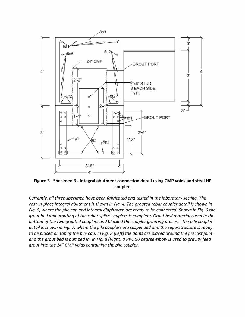
Figure 3. Specimen 3 - Integral abutment connection detail using CMP voids and steel HP
coupler.
Currently, all three specimen have been fabricated and tested in the laboratory setting. The cast-in-place integral abutment is shown in Fig. 4. The grouted rebar coupler detail is shown in Fig. 5, where the pile cap and integral diaphragm are ready to be connected. Shown in Fig. 6 the grout bed and grouting of the rebar splice couplers is complete. Grout bed material cured in the bottom of the two grouted couplers and blocked the coupler grouting process. The pile coupler detail is shown in Fig. 7, where the pile couplers are suspended and the superstructure is ready to be placed on top of the pile cap. In Fig. 8 (Left) the dams are placed around the precast joint and the grout bed is pumped in. In Fig. 8 (Right) a PVC 90 degree elbow is used to gravity feed grout into the 24” CMP voids containing the pile coupler.

Figure 4. CIP integral abutment specimen in preparation for load testing.
a) Pile Cap b) Abutment Diaphragm
Figure 5. Grouted coupler specimen prior to grouting.

Figure 6. Grouted Coupler Specimen
Figure 7. Pile Coupler Integral Diaphragm
Figure 8. Pile Coupler Grouting
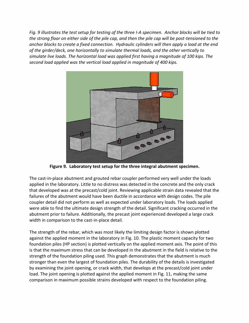
Fig. 9 illustrates the test setup for testing of the three I-A specimen. Anchor blocks will be tied to the strong floor on either side of the pile cap, and then the pile cap will be post-tensioned to the anchor blocks to create a fixed connection. Hydraulic cylinders will then apply a load at the end of the girder/deck, one horizontally to simulate thermal loads, and the other vertically to simulate live loads. The horizontal load was applied first having a magnitude of 100 kips. The second load applied was the vertical load applied in magnitude of 400 kips.
Figure 9. Laboratory test setup for the three integral abutment specimen.
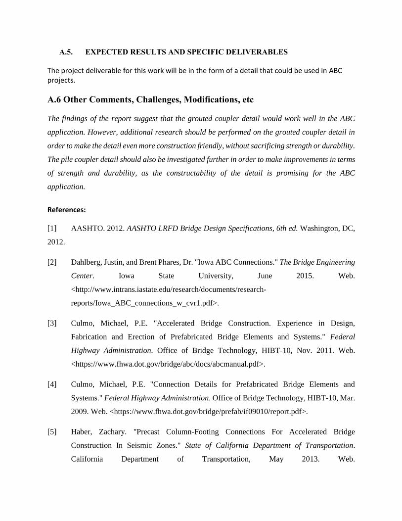
The cast-in-place abutment and grouted rebar coupler performed very well under the loads applied in the laboratory. Little to no distress was detected in the concrete and the only crack that developed was at the precast/cold joint. Reviewing applicable strain data revealed that the failures of the abutment would have been ductile in accordance with design codes. The pile coupler detail did not perform as well as expected under laboratory loads. The loads applied were able to find the ultimate design strength of the detail. Significant cracking occurred in the abutment prior to failure. Additionally, the precast joint experienced developed a large crack width in comparison to the cast-in-place detail. The strength of the rebar, which was most likely the limiting design factor is shown plotted against the applied moment in the laboratory in Fig. 10. The plastic moment capacity for two foundation piles (HP section) is plotted vertically on the applied moment axis. The point of this is that the maximum stress that can be developed in the abutment in the field is relative to the strength of the foundation piling used. This graph demonstrates that the abutment is much stronger than even the largest of foundation piles. The durability of the details is investigated by examining the joint opening, or crack width, that develops at the precast/cold joint under load. The joint opening is plotted against the applied moment in Fig. 11, making the same comparison in maximum possible strains developed with respect to the foundation piling.
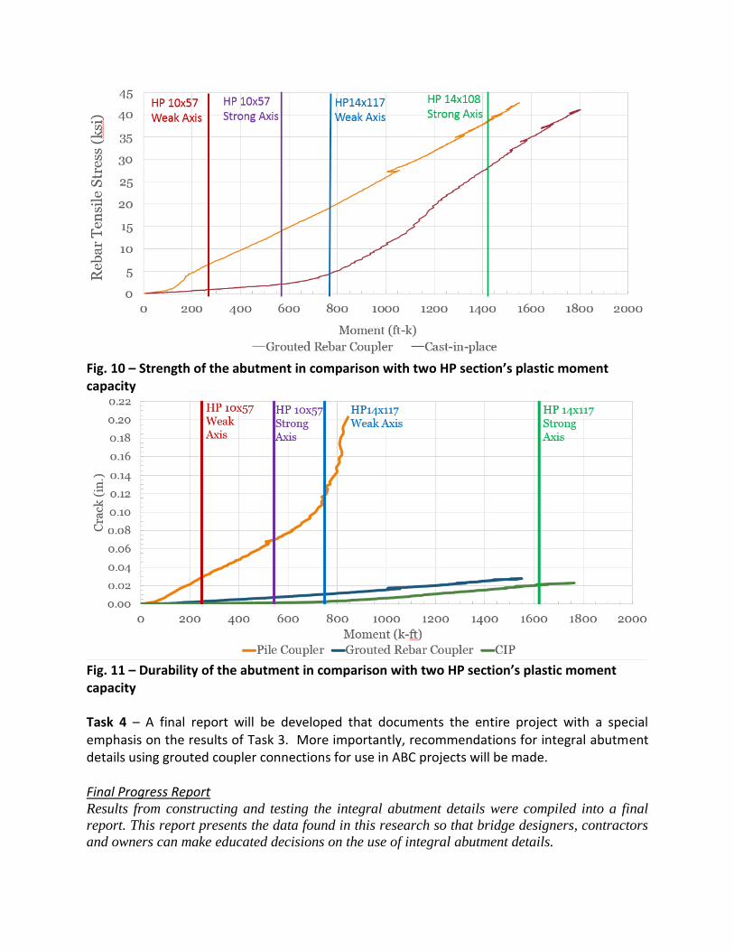
Fig. 10 – Strength of the abutment in comparison with two HP section’s plastic moment capacity
Fig. 11 – Durability of the abutment in comparison with two HP section’s plastic moment capacity
Task 4 – A final report will be developed that documents the entire project with a special emphasis on the results of Task 3. More importantly, recommendations for integral abutment details using grouted coupler connections for use in ABC projects will be made.
Final Progress Report Results from constructing and testing the integral abutment details were compiled into a final
report. This report presents the data found in this research so that bridge designers, contractors
and owners can make educated decisions on the use of integral abutment details.
A.5. EXPECTED RESULTS AND SPECIFIC DELIVERABLES
The project deliverable for this work will be in the form of a detail that could be used in ABC projects.
A.6 Other Comments, Challenges, Modifications, etc
The findings of the report suggest that the grouted coupler detail would work well in the ABC
application. However, additional research should be performed on the grouted coupler detail in
order to make the detail even more construction friendly, without sacrificing strength or durability.
The pile coupler detail should also be investigated further in order to make improvements in terms
of strength and durability, as the constructability of the detail is promising for the ABC
application.
References:
[1] AASHTO. 2012. AASHTO LRFD Bridge Design Specifications, 6th ed. Washington, DC,
2012.
[2] Dahlberg, Justin, and Brent Phares, Dr. "Iowa ABC Connections." The Bridge Engineering
Center. Iowa State University, June 2015. Web.
<http://www.intrans.iastate.edu/research/documents/research-
reports/Iowa_ABC_connections_w_cvr1.pdf>.
[3] Culmo, Michael, P.E. "Accelerated Bridge Construction. Experience in Design,
Fabrication and Erection of Prefabricated Bridge Elements and Systems." Federal
Highway Administration. Office of Bridge Technology, HIBT-10, Nov. 2011. Web.
<https://www.fhwa.dot.gov/bridge/abc/docs/abcmanual.pdf>.
[4] Culmo, Michael, P.E. "Connection Details for Prefabricated Bridge Elements and
Systems." Federal Highway Administration. Office of Bridge Technology, HIBT-10, Mar.
2009. Web. <https://www.fhwa.dot.gov/bridge/prefab/if09010/report.pdf>.
[5] Haber, Zachary. "Precast Column-Footing Connections For Accelerated Bridge
Construction In Seismic Zones." State of California Department of Transportation.
California Department of Transportation, May 2013. Web.
<http://wolfweb.unr.edu/homepage/saiidi/caltrans/GroutedCouplers/PDFs/CCEER-13-
08-July2-13.pdf>.
[6] Hosteng, Travis. "Laboratory Investigation of Grouted Coupler Connection Details for
ABC Bridge Projects." Bridge Engineering Center. Iowa Department of Transportation,
Federal Highway Administration, Aug. 2015. Web.
<http://www.intrans.iastate.edu/research/documents/research-
reports/grouted_coupler_connections_for_ABC_w_cvr.pdf>.
[7] INDOT. "Integral Abutment Design." Load and Resistance Factor Design (LRFD)
Examples. Indiana Department of Transportation, 1998. Web. 2015.
<http://www.in.gov/dot/div/contracts/design/lrfd/>.
[8] Jansson, Peter, P.E. "Evaluation of Grout-Filled Mechanical Splices for Precast Concrete
Construction." Www.michigan.gov. Michigan Department of Transportation Construction
and Technology Division, May 2008. Web.
[9] Nelson, James, P.E. "IOWA ACCELERATED BRIDGE CONSTRUCTION
HISTORY." Iowa DOT. Precast Concrete Institute, 2014. Web.
<http://www.iowadot.gov/bridge/abc/Presentations/2014%20PCI%20Iowa%20ABC%20
8%20-%20Final%20Revisions%20Accepted.pdf>.
[10] Noureddine, Issam. "Plastic Energy Absorption Capacity of #18 Reinforcing Bar Splices
under Monotonic Loading." State of California Department of Transportation. N.p., 1996.
Web.
<http://www.dot.ca.gov/hq/esc/earthquake_engineering/Research_Reports/vendor/csus/Pl
astic%20Energy%20Absorption%20of%20%2318%20Bar%20Splices%201996.pdf>.
[11] Rouse, Jon, and Brent Phares, Dr. "Laboratory and Field Testing of an Accelerated Bridge
Construction Demonstration Bridge: US Highway 6 Bridge over Keg Creek." The Bridge
Engineering Center. Iowa State University, Apr. 2013. Web.
<http://www.intrans.iastate.edu/research/documents/research-
reports/keg_creek_bridge_w_cvr.pdf>.

[12] Rowell, Stephen. High Strain-Rate Testing of Mechanical Couplers. Rep. no. ERDC TR-
09-8. N.p.: US Army Corps of Engineers, 2009. Print.
[13] Transportation Research Board. "Innovative Bridge Designs for Rapid
Renewal." Transportation Research Board. Strategic Highway Research Program, Feb. 13.
Web. <http://onlinepubs.trb.org/onlinepubs/shrp2/SHRP2_S2-R04-RR-2.pdf>.