Strength Assessment Techniques - utm.my. •Establish density ... core (a diagonal shear crack is OK...
58
Strength Assessment Techniques MAB1033 Structural Assessment & Repair Prof. Dr. Azlan Abdul Rahman Faculty of Civil Engineering Universiti Teknologi Malaysia
-
Upload
nguyenmien -
Category
Documents
-
view
215 -
download
1
Transcript of Strength Assessment Techniques - utm.my. •Establish density ... core (a diagonal shear crack is OK...

Strength Assessment Techniques
MAB1033 Structural Assessment & Repair
Prof. Dr. Azlan Abdul Rahman
Faculty of Civil Engineering
Universiti Teknologi Malaysia

Main Reference
Bungey, J.H.
‘The Testing of Concrete in Structures’
2nd. Edition, Blackie Academic & Professional,
Chapman & Hall, London 1994

Techniques for Strength Assessment
• Core testing represents the most reliable method of establishing in-situ concrete strength.
• Core-drilling is relatively ‘destructive’ by reason that it left a hole in the structure.
• Other ‘partially-destructive’ techniques for assessing strength of surface concrete are generally less reliable than cores but cause less damage & give instant results : penetration resistance, pull-out, pull-off, internal fracture & break-off methods.

Core Drilling Machine

Core Drilling & Testing
• Refer Concrete Society TR11 (1987) & BS 1881 Part 120 (1983) – detailed guidance & recommendations.
• Other uses of cores : visual inspection to assess concrete uniformity (aggregate distribution & compaction); samples for petrographic or chemical analysis.

Purpose of Core Drilling & Testing
• Assessment of Potential Strength
• Assessment of In-situ Cube Strength
• Assessment of Load Factor to carry : actual, designed & projected loads
• Assessment of degree & extent of deterioration due to loads or environmental causes

Planning for Core Drilling
• Establish reasons for core testing : specification compliance; structural adequacy; etc.
• Obtain information on location of suspect concrete (NDT survey or records).
• Establish locations, number & size of cores.
• Other logistics planning.

Coring Locations
• For in-situ cube strength : cores may be drilled from any location of interest (avoiding reinforcement steel). Zones of lowest strength are expected to be towards the top elements.
• For potential strength : should avoid –
- top 20% of lifts
- badly compacted concrete
- reinforcement steel
• Covermeters used to locate position of steel.

Number of Cores
• Depends on the required accuracy. For standard size cores the 95% confidence limit on in-situ cube strength is taken to be
• The number of cores from a location should reflect the volume of concrete liable to render a particular element structurally inadequate; the importance of the element; the value of work at risk.
• Minimum number of cores required to obtain a potential strength estimate of a batch of concrete is 4. (For uncertain zone + 15% is expected)
%12
n

Size of Cores
• Standard size is 100mm or 150mm diameter (D) for up to 25mm and 40mm aggregate size respectively
• 150mm is more reliable
• Core length should be between 1.0D and 2.0D.
• 1.0D – 1.2D is preferred due to : limiting drilling costs; damage, variability; geometric effects on testing.
• 100mm may be justified to avoid steel or due to physical constraints.
• Below this size is classified as ‘small cores’ (but diameter should not be less than 3x max. aggregate size or not less than 50mm).

Core Drilling
• Use rotary cutting tool with diamond bits.
• Portable equipment but heavy and firmly supported to prevent movement which will result in distorted or broken core.
• Water supply to lubricate the cutter.
• Uniformity of pressure : need skilled operator.
• Hand-held equipment available for small cores up to 75mm diameter.
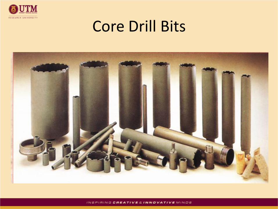
Core Drill Bits

Strengthened Drill Tip

Core Drilling
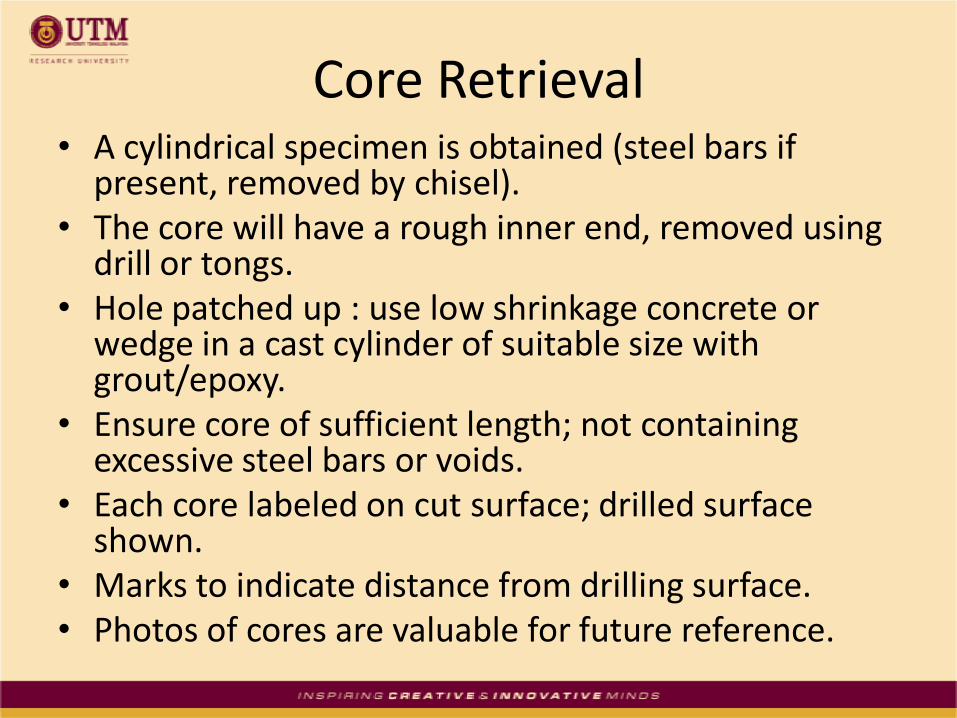
Core Retrieval• A cylindrical specimen is obtained (steel bars if
present, removed by chisel).• The core will have a rough inner end, removed using
drill or tongs.• Hole patched up : use low shrinkage concrete or
wedge in a cast cylinder of suitable size with grout/epoxy.
• Ensure core of sufficient length; not containing excessive steel bars or voids.
• Each core labeled on cut surface; drilled surface shown.
• Marks to indicate distance from drilling surface.• Photos of cores are valuable for future reference.

View inside core hole

Core Marking
50
100
150
200
AA/1V
Coring depth (mm)
Location reference
Orientation reference
(relative to casting)

Core Samples

Prior to Core Testing (Visual)
• Visual examination of core : aggregate type, size & characteristics (wet surface); distribution, honeycombing, cracks defects (dry surface).
• Size & location of steel noted.
• Voids classified in terms of excess voidage & compare with standard photos from CSTR 11 & BS1881 : Part 120.
• Estimated value of excess voidage is required for potential strength calculation.

Description of Voids in Core
• Small voids (0.5 to 3mm)
• Medium voids (3 – 6mm)
• Large voids (> 6mm)
• Honeycombing is when these voids are interconnected.

Visual Examination of the Core Samples
Prior to Core Testing (Trimming & Capping)
• Trimming with masonry or diamond saw to obtain parallel ends.
• No need capping if ends are prepared by grinding.
• Capping with high alumina cement mortar or sulphur-sand mixture to get parallel end surfaces.
• Caps should be kept as thin as possible. BS 1881 Part 120 specifies max. cap 10mm.

Prior to Core Testing (Dimension & Storage)
• Diameter & length of specimen must be measured to nearest 1mm & compared with tolerances in BS1881 Part 120.
• Cores to be stored in water at 20+-2oC for at
least 48 hours prior to testing.
• May be removed for up to 1 hour for grinding if replaced in water for at least 1 hour.

Preparation for Core Testing

Prior to Core Testing (Density Measurement)
• Measure volume (Vu) of trimmed core by water displacement.
• Establish density of capping material (Dc).
• Before compression test, weigh soaked/surface-dry capped core in air & water to determine gross weight (Wt) & volume Vt.
• If steel present, removed & determine weight Ws and volume Vs.
• Calculate saturated density of concrete in an uncapped core from formula.

Density Calculation
su
sutcta
VV
WVVDWD

Core Testing for Strength
• Compression testing at a rate within a range 12-24N/(mm2.min).
• Mode of failure recorded.
• If there is cracking of caps or separation of cap & core, result is considered doubtful.
• Ideally cracking should be similar all round the core (a diagonal shear crack is OK except for short cores).
• Core strength = (maximum load) divided by (X-sectional area)

Core Compression Test
Factors Affecting Measured Core Compressive Strength
• Moisture condition : saturated specimen has a value 10-15% lower than a comparable dry specimen.
• Curing regime (strength development) will be different from the time of cutting.
• Voids in core will reduce measured strength.
• L/D ratio of core : as the ratio increases, the measured strength will decrease due to the effect of specimen shape on stress concentration whilst under test. (L/D=2.0 as datum).
• Diameter of core may influence measured strength and variability (min. dia./max. aggregate ratio = 3)

Factors Affecting Measured Core Compressive Strength
• Direction of drilling : measured strength of a specimen drilled vertically relative to the direction of casting is greater than that for a horizontally drilled specimen from the same concrete. (layering effects) ~ 8%
• Method of capping : capping material stronger than core & not excessively thick should not have significant effects.

Effect of Reinforcement
• Research indicates that reduction in measured strength due to reinforcement is about 10%.
• Affects of size, location & bond are difficult to assess & therefore reinforcement must be avoided wherever possible.
• If present, correction may be applied to the measured core strength using a formula.
• Disregard core if correction > 10%.

Correction for Reinforcement
l
hx
c
r
.
.5.10.1
l
hx
c
r
.
.5.10.1
The correction factor for a core
containing a bar perpendicular to
its axis
Correction factor for core
containing multiple bars

Estimation of Cube Strength
Estimation of an Equivalent Cube Strength corresponding to a particular core result must account for 2 main factors :
1) Effect of L/D ratio which requires a correction factor to convert the core strength to an equivalent standard cylinder strength.
2) Conversion to an equivalent cube strength using relationship between strengths of cylinders and cubes.

Estimation of Cube Strength
15.1
25.3
f
15.1
0.3
f
Estimated Potential Cube
Strength for Horizontally
Drilled Core
Estimated Potential Cube
Strength for Vertically Drilled
Core

Variability in Core Strength Test
• Coefficient of variation (CoV) due to testing effects is about 6% for carefully cut & tested cores (cube ~ 3%).
• Damage caused by drilling is significant for old brittle concretes due to internal cracking.
• Results for potential strength should also be examined statistically to identify abnormally low (or high) result. (See Bungey for further reference).

Example
A 100mm diameter core drilled horizontally from a concrete beam contains one 20mm reinforcement bar normal to the core axis and located at 30mm from one end. The core is prepared for standard compression test and the measured core length after capping is 120mm.
Following BS1881 procedure for core strength testing, the measured crushing load is 160kN with normal failure mode. Use the Concrete Society procedure to calculate the actual cube strength.

Partially Destructive Tests for Assessing Strength
Less reliable than core testing but cause less damage & give instant results :
• Penetration resistance (Windsor probe)
• Pull-out (Lok-test & Capo test)
• Break-off test
• Pull-off test
• Internal fracture
Penetration Resistance Test
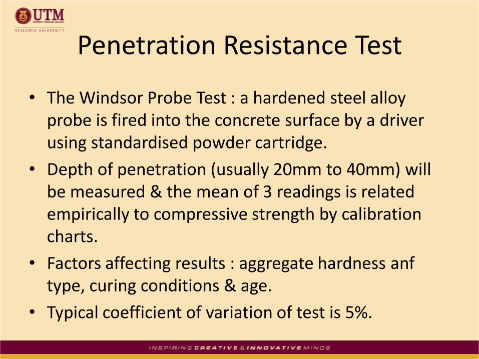
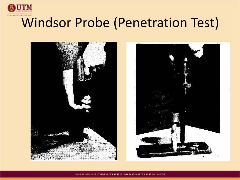
• The Windsor Probe Test : a hardened steel alloy probe is fired into the concrete surface by a driver using standardised powder cartridge.
• Depth of penetration (usually 20mm to 40mm) will be measured & the mean of 3 readings is related empirically to compressive strength by calibration charts.
• Factors affecting results : aggregate hardness anftype, curing conditions & age.
• Typical coefficient of variation of test is 5%.

Windsor Probe Test
Windsor Probe (Penetration Test)

Pull-Out TestA circular steel insert is located below concrete surface and pulled by means of a calibrated hydraulic jack against a reaction ring bearing on the surface.Two versions : 1. Lok-Test which uses 25mm diameter insert cast into
concrete at depth of 25mm2. Capo-Test in which a steel ring is expanded into a groove
undercut from an 18mm diameter drilled hole.• In both types, a hand operated jack is used with a 55mm
reaction ring and average of 6 readings used for correlation purpose. Typical CoV of test is 7%.
• Lok-Test is useful in monitoring in-situ strength development (long-term) and Capo-Test requires skill & experience and most useful for in-situ strength estimation where calibration is not available.

Pull Out (Lok Test)
Lok-Test Insert

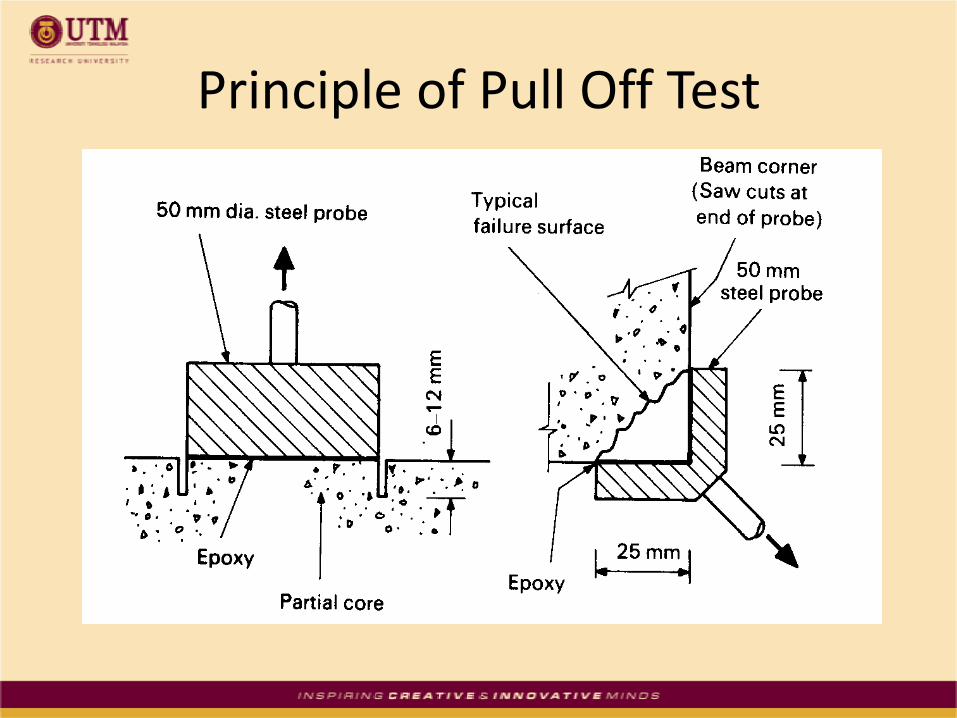
Pull-Off Test
• A circular metal disc is bonded to the surface of concrete by an adhesive.
• The disc is pulled-off by applying a direct tensile force using a hand operated equipment bearing.
• The peak load is measured, enabling a tensile strength to be calculated and an equivalent cube strength is estimated with the aid of correlation graph.
• CoV of test is about 10%.
Principle of Pull Off Test

The Pull-Off Test Device

Break-Off Test
• The method measures the force required to break-off a 55mm diameter core which has been formed within the concrete at a depth of 70mm.
• This is done by a disposable tubular plastic sleeve inserted into freshly placed concrete, or by drilling if existing concrete is to be tested.
• An enlarged slot is formed near the surface & load cell is inserted to provide a transverse force to cause flexural failure at the base of core.
• The break-off force may be related to bending strength by means of calibration charts.
• The mean of 5 tests required. CoV is about 10%.

Principle of Break Off Test
Enlarged slot

Break-Off Test Device

Internal Fracture Test
• A 6mm diameter hole is drilled about 35mm deep into concrete using a masonry drill.
• An expanding wedge anchor bolt is fixed into the hole to a depth of 20mm and pulled against an 80mm diameter reaction tripod by a torque-meter acting on a greased nut.
• The peak torque is observed and average of 6 readings may be related to compressive strength with the aid of correlation curve.
• Typical CoV is about 15%.

Principle of Internal Fracture

Non-Destructive Tests (NDT)for Strength Assessment
• UPV and surface hardness measurements can identify location and extent of suspect concrete in a structure.
• Calibrations are necessary prior to use for absolute strength estimates.
• Calibration between measured parameter and strength is difficult.
• Sometimes possible to develop strength correlations by using cores with in-situ NDT.
Maturity Measurement• Based on recorded temperature measurements
taken at the interior of the concrete element to evaluate a maturity as a function of temperature & time.
• For a particular concrete mix, it is possible to establish a relationship between strength and maturity.
• Measurements obtained from thermocouples or temperature measurement devices embedded at appropriate locations within a pour, and connected to automatic recorder.

Temperature Matched Curing
• Involves the use of a temperature sensor located at a critical position within the pour to control the temperature of a water tank in which standard control specimens are placed.
• The curing regime of the specimens follows that of the pour & may be tested by crushing.
• BS DD92 (1984) offers guidance on these procedures.
• This technique is useful in monitoring early age strength development.

Concrete Temperature & Maturity
Concrete Temperature Meter Concrete Maturity Meter

Coefficient of Variation of Results for Principal Methods
Principal Test MethodTypical CoV for individual
member of good quality
construction
Core Testing - ‘standard’
- ‘small’
10%
15%
Pull-Out Test 7%
Pull-Off Test 10%
Break-Off Test 10%
Windsor Probe 5%
Internal Fracture 15%
Ultrasonic Pulse Velocity Test 2.5%
Rebound Hammer Test 4%

Coefficient of Variation (CV%)

Rebound Hammer –UPV Correlations
ISO-Strength Curves for Reference
Concrete (Samarin & Smorchevsky) Multiple Correlation (Nomogram)

Terima Kasih