
Streets and roads (draft) - Sustrans · Streets and roads (draft) February 2015. ... whether to...
95
1 September 2014 Sustrans Design Manual Chapter 4 Streets and roads (draft) February 2015
Transcript of Streets and roads (draft) - Sustrans · Streets and roads (draft) February 2015. ... whether to...

1September 2014
Sustrans Design Manual Chapter 4
Streets and roads (draft)
February 2015

Sustrans Design Manual • Chapter 4: Streets and roads (2015, draft)
2 February 2015
About SustransSustrans makes smarter travel choices possible, desirable and inevitable. We’re a leading UK charity enabling people to travel by foot, bike or public transport for more of the journeys we make every day. We work with families, communities, policy-makers and partner organisations so that people are able to choose healthier, cleaner and cheaper journeys, with better places and spaces to move through and live in.
It’s time we all began making smarter travel choices. Make your move and support Sustrans today. www.sustrans.org.uk
Head Office Sustrans 2 Cathedral Square College Green Bristol BS1 5DD
© Sustrans February 2015
Registered Charity No. 326550 (England and Wales) SC039263 (Scotland)
Photography: Sustrans or CTC Benchmarking unless noted otherwise. Cover photo: LB Camden
Issue level: 01
Owned by: NCN Director
Contact: [email protected]
ContentsThis chapter of the Sustrans Design Manual should be read in conjunction with Chapter 1 “Principles and processes for cycle friendly design.” That chapter includes key guidance on core design principles, whether to integrate with or segregate from motor traffic, the space required by cyclists and other road users as well as geometrical considerations. Readers are also directed towards the “Handbook for cycle-friendly design” which contains a concise illustrated compendium of the technical guidance contained in the Design Manual. This chapter has initially been issued as a draft and it is intended that it be reviewed during 2015; feedback on the content is invited and should be made by 31 May 2015 to [email protected]
1. Key principles
2. Overview of design approaches
3. Traffic volume and speed reduction
Overview
Filtered permeability
Contraflow cycling
Vehicle restricted areas
Weight, height and width restrictions
Traffic calming
Mixed priority routes
Shared space
Quiet streets
Cycle streets
Home zones
Community street design
Use of 1057 markings in shared traffic lanes
4. Reallocation of space between users
Overview
Cycle lanes
Light segregation and ‘hybrid’ (stepped) cycle tracks
Cycle tracks
5. Rural roads
6. References

3February 2015
Sustrans Design Manual • Chapter 4: Streets and roads (2015, draft)
1. Key principles• Manual for Streets1 defines ‘streets’ and ‘roads’ and follows:
• roads are highways whose main function is accommodating the movement of motor traffic
• streets are typically lined with buildings and public spaces, and while movement is still a key function, there are several others, of which the place function is the most important. Place functions include economic and social activities
• Manual for Streets identifies that attractive and well-connected permeable street networks encourage more people to walk and cycle to local destinations, improving their health while reducing motor traffic, energy use and pollution
• design approaches for cyclists along streets and roads range from cyclists mixing with other traffic without cycling-specific infrastructure, through a spectrum of infrastructure solutions which provide increasing separation from traffic, culminating in full segregation on cycle tracks with a verge or margin strip
• the appropriate type of provision for cyclists on links is influenced by:
• movement functions (including traffic volume, speed, proportion of HGVs and function in the cycle network)
• place functions; pedestrian activity, parking, deliveries and drainage, utilities and lighting requirements
• physical dimensions of the highway; and interface with the provision at junctions and adjoining sections of route
• in locations with a high place and low movement function, appropriate provision will usually mix cycle users with other traffic in a low speed (and ideally low traffic volume) environment. A range of interventions (shared space principles, quiet streets, cycle streets, home zones, community street design) can be employed to emphasise the place function in residential neighbourhoods and to reduce traffic speeds sufficiently to enable mixing of cycle users and other traffic. Shared space principles can also help to reduce speeds and promote more civilised interactions between road users in high traffic locations, without the need for cycling-specific measures
• parts of the network with a high movement function and low place function will need a higher degree of segregation of cyclists from other traffic. However, some speed reduction may also be part of the solution to aid permeability and improve safety for people walking and cycling
• any of the measures that involve reallocation of space between users (e.g. cycle lanes, light segregation, hybrid/stepped cycle tracks, fully segregated cycle tracks) can be implemented either by reallocating carriageway space or converting the verge and/or footway to allow cycle use. Wherever possible, reallocation of carriageway space should be selected in preference to taking space from the verge or footway
1 Manual for Streets 1, Department for Transport, March 2007

Sustrans Design Manual • Chapter 4: Streets and roads (2015, draft)
4 February 2015
2. Overview of design approaches2.1This section describes the range of design approaches that can used to provide for cycling on streets and roads. It addresses techniques used on highway links2 (both on the carriageway and on the verge/footway) and at minor side road junctions along the link.
2.2Guidance on providing for cyclists at larger junctions and mid-link crossings is covered in Chapter 7: Cyclists at junctions and crossings. Guidance on traffic-free routes away from the highway is addressed in Chapter 5: Traffic free routes: conceptual design and Chapter 6: Traffic free routes: detailed design.
2.3Design approaches for cyclists along streets and roads range from cyclists mixing with other traffic without cycling-specific infrastructure, through a spectrum of infrastructure solutions which provide increasing separation from traffic, culminating in full segregation on cycle tracks with a verge or margin strip. The design approaches are summarised in Table 2.1.
2.4Chapter 1: Principles and processes for cycle friendly design provides guidance on how to select the appropriate form of provision for cyclists on a section of route. Key requirements and constraints that influence the type of provision include:
• movement functions of the link : • the function in the cycle network (main, secondary or access route) • type(s) of target cycle users • the current and forecast volumes of cyclists and pedestrians; and • the role of the route for other traffic • traffic volume, speed and proportion of HGVs (existing and potential)
• place functions, including social activity, aesthetic character and sensitivity
• parking, deliveries and drainage, utilities and lighting functions – which can impact significantly on the feasibility and cost of different types of provision
• physical dimensions of the highway
• traffic congestion – may favour cycle lanes or tracks to by-pass vehicle queues
• what range of interventions will provide appropriate levels of service for cyclists
• interface with the provision at junctions and adjoining sections of route
2 Links: sections of the network between junctions

5February 2015
Sustrans Design Manual • Chapter 4: Streets and roads (2015, draft)
Table 2.1 Summary of design approaches for cyclists on streets and roads
Category Cycle provision Achieved by
Shared carriageway
Mixed traffic
(optional markings to indicate cycle route)
Traffic volume reduction• filtered permeability• contraflow cycling• vehicle restricted areas• signing strategy and/orSpeed reduction• traffic calming (physical/psychological)• mixed priority routes• shared space• quiet streets and cycle streets• home zones and DIY Streets
Cycle lanes
(segregation by white line)
Advisory cycle lanes
Mandatory cycle lanes
Shared bus/cycle lanes
Reallocation of carriageway space
or
Reallocation of verge and/or footway (use only as a last resort)
some traffic speed and/or volume reduction may also be desirable
Physical segregation
Light segregation ‘Hybrid’ (stepped) track
Physical segregation with verge or margin strip
Cycle-only track
Segregation shared use track
Unsegregated shared use track
2.5In all cases, the design solution(s) selected must deliver high standards of the five core design principles, which in combination contribute to a good level of service. These are:
• coherence - high standards of connectivity, consistent provision, well-signed
• directness - routes based on desire lines, with minimal detours or delays and offering a time-advantage over other traffic
• safety - low risk of injury, good personal security; perceived as safe
• comfort - minimise gradients and loss of momentum; avoid complex manoeuvres; smooth, non-slip, well-drained surfaces; minimise noise, spray, dazzle from traffic
• attractiveness - aesthetically pleasing, interesting, complements surroundings
2.6The design should also cater for significant increases in cycle usage, or be readily adaptable to accommodate cycling growth.
I n c
r e
a s
i n g
s
e p
a r
a t i
o n
f r
o m
t r
a f
f i c

Sustrans Design Manual • Chapter 4: Streets and roads (2015, draft)
6 February 2015
2.8There are two main ways of using the speed-flow diagram in Figure 2.1:
• determine what type of provision(s) may be appropriate for the observed speed and volume of traffic in a given highway environment
• select the preferred type of provision - based on volume of cyclists and pedestrians, ‘place functions’ (street activity and character), available space, continuity with adjacent sections of route etc. - and then determine how much the speed and volume of traffic would need to be reduced to enable this
2.9Reducing traffic speeds and volumes can offer many benefits, both for cycle users and pedestrians and other users of streets and roads. These include:
• safety benefits - real and perceived - for all road users
• improved pedestrian and cycle permeability and reduced severance
• improved comfort for all street users, facilitating social activity and active travel
Tota
l tw
o w
ay v
ehic
le fl
ow
(100
0 ve
h/da
y or
100
veh
/hou
r)
12
11
10
98
7
6
5
4
3
2
1
SHARED CARRIAGEWAY
CYCLE LANE
Congested and becomes unsuitable for cycling on the carriageway
Cycle-specific infrastructure can be considered but is not normally beneficial
PHYSICAL SEGREGATION
Motor vehicle speeds much above 40mph become unsuitable for cycling on the carriageway
Very
Low
Low
Med
ium
Hig
hVe
ry H
igh
10 20 30 40 50 60
85th%ile motor vehicle speed (mph)
PHYSICAL SEGREGATION WITH VERGE
CYCLE LANE
Figure 2.1 Influence of traffic speed/volume on type of cycling provision
Traffic volume and speed2.7Traffic volume and speed are key determinants (but not the only consideration) of the types of provision that will be appropriate on a link. Figure 2.1 illustrates how traffic volume and speed may influence the decision on the need to segregate cyclists from other traffic, and demonstrates how restraint of traffic speeds and volumes is central to creating satisfactory conditions for people to cycle on the carriageway. The threshold values are intended to reflect the needs of a novice cyclist who is trained to National Standards/Bikeability Level 2, and it is likely that main cycle routes will provide a greater degree of segregation than secondary or access routes.

7February 2015
Sustrans Design Manual • Chapter 4: Streets and roads (2015, draft)
• opportunities for wider public realm enhancements, by reducing movement space requirements and traffic intrusion
• enabling space-efficient mixed use of street space, which can accommodate both place and movement functions and is adaptable for growth in walking and cycling
2.10Because of these wider benefits, it is recommended that at the outset designers always consider opportunities for traffic speed and/or volume reduction as an option. Where this can provide for safe and convenient cycling sharing the carriageway with other traffic, other infrastructure interventions will commonly not be needed. Even where cycle specific infrastructure is deemed appropriate, designers are recommended to consider if some traffic speed and/or volume reduction should form part of the design solution.
Movement and place2.11Traffic speed and volume relate to movement function which, as noted above, is only one of the factors which influence the type of provision. In streets with high place function (e.g. high streets or town squares), segregated cycle tracks will generally not be a suitable provision because of the complex pedestrian movements and competition for space with other social activities and parking and loading requirements. The impact of placemaking on street design is discussed in Chapter 3.
2.12In general, in parts of the network with a high place and low movement function, appropriate provision will mix cycle users with other traffic in a low speed (and ideally low traffic volume) environment. Parts of the network with a high movement function and low place function will need a higher degree of segregation of cyclists from other traffic. However, some speed reduction may also be part of the solution to aid permeability and improve safety for people walking and cycling.
2.13Manual for Streets 2 (Fig 2.2) illustrates how different street types fall within a place and movement framework. In the 2014 London Cycling Design Standards (section 1.2.2), TfL develops this to identify appropriate types of cycling provision based on place and movement functions. The TfL approach defines all streets as one of nine street types based on place and movement function and then assigns a subset of cycling interventions appropriate for each street type (LCDS 2014 Figures 1.3 and 1.4).
2.14Such an approach, used alongside Figure 2.1, can help take account of the place function when selecting the appropriate type of infrastructure, and may be developed as a useful tool for use in other types of local authority area.

Sustrans Design Manual • Chapter 4: Streets and roads (2015, draft)
8 February 2015
3.3m
4.1m
4.8m
5.5m
Figure 2.2 Indicative carriageway widths for
various traffic compositions at low speed (adapted from
Manual for Streets)
Reallocation of space2.15Any of the measures that involve reallocation of space between users (e.g. cycle lanes, hybrid (stepped) cycle tracks, fully segregated cycle tracks) can be implemented either by reallocating carriageway space or converting the verge and/or footway to allow cycle use. Wherever possible, reallocation of carriageway space should be selected in preference to taking space from the verge or footway. Reallocating carriageway space will commonly be achievable at low cost and can contribute to demand management, without taking space from pedestrians or other non-movement activities.
2.16Where physical segregation of cyclists from other traffic is appropriate and pedestrian usage is also high, there should also be a presumption for segregated cycle tracks rather than cyclists and pedestrians having to share the same space alongside the carriageway; however, each situation needs to be considered on a case by case basis.
Lane widths 2.17Unless motor traffic flows are light, and drivers can cross easily into the opposing carriageway to pass cyclists, traffic lane widths of less than 3m or more than 4m should be used. Lane widths in the critical range of 3.2m to 3.9m should be avoided as these create conditions unsuitable for cycling on the carriageway unless traffic speeds and volumes are low so that drivers can cross easily into the opposing lane to pass a cyclist comfortably.
2.18Figure 2.2, adapted from Manual for Streets, provides an indication of what various carriageway widths can accommodate at low speeds (though not necessarily recommendations) and Figure 2.3, taken from the Cardiff Cycling Design Guide, provides guidance on the size of vehicles that various traffic lane widths can accommodate. Further guidance on traffic lane widths is given in Manual for Streets 2.

9February 2015
Sustrans Design Manual • Chapter 4: Streets and roads (2015, draft)
2.19Whilst traffic lane widths of 3.65m have often been provided as standard in the United Kingdom, lane widths of 3.0m have been used in many parts of the country on urban roads for some time, and can accommodate most typical vehicles (including HGVs) at speeds up to 40mph (Transport and the Urban Environment, IHT 1997).
2.20Where flows of large vehicles are low, and speeds are modest, lane widths as narrow as 2.75m can accommodate car traffic comfortably. Larger vehicles can pass each other at this width at low speed with care.
Design solutions2.21The following sections describe each of the types of provision listed in Table 2.1. The chapter is structured around the primary means of achieving each type of provision, as follows:
• traffic volume and speed reduction
• reallocation of space between users
2.22In practice, design solutions along a link may include traffic and/or speed reduction as well as reallocation of space to provide segregation between transport modes; for example 20mph limits combined with cycle lanes where there are traffic queues.
2.23Whilst it is essential to ensure appropriate treatment of each section of the network, it is also important to provide continuity for cyclists along a route. The management of the interface between adjacent sections of route is important to ensure cyclists retain a degree of consistency and a suitable level of service throughout their journey.
2.75m
2.5m
2.0m
3.00m
3.20m
3.65m
Figure 2.3 Illustration of size of vehicles various lane widths can accommodate (Cardiff Cycle Design Guide)

Sustrans Design Manual • Chapter 4: Streets and roads (2015, draft)
10 February 2015
3. Traffic volume and speed reductionOverview3.1Where traffic volumes and speeds are low, or can be made sufficiently low, cyclists will generally be able to share the carriageway and mix with other traffic without the need for cycle-specific infrastructure (Figure 2.1).
3.2Flows below 1500 vehicles/day and speeds below 20mph should be the target conditions, for cyclists mixing with other traffic in urban areas.
3.3Streets or roads where vehicle flows are less than 3000 vehicles/day and 85 percentile vehicle speeds up to about 20mph can still be classified as quiet streets and under these speed/flow conditions lanes or tracks will generally not be required on the link.
3.4Within town centres and other locations with a high place function segregation may be less practicable and design solutions that enable cyclists to share the space with other traffic should be considered where speeds are low, for traffic volumes up to about 6000 vehicles per day. At greater traffic volumes increasing congestion makes it more difficult to share the carriageway so some form of segregation may need to be considered.
3.5These threshold speed/flow values are a necessary condition for many cyclists to mix safely and comfortably with traffic. Where traffic speeds and/or volumes exceed these levels, the decision to intervene to reduce speeds or volumes – in preference to segregating cyclists from traffic - will be determined by other functions of the street, including place function, complexity and volume of pedestrian movements, parking and loading requirements, street dimensions and the traffic function and cycling function of the link in the network.

11February 2015
Sustrans Design Manual • Chapter 4: Streets and roads (2015, draft)
3.6Three street types where speed and volume reduction are generally the preferred approach to accommodate cyclists mixing with other traffic are shown in Table 3.1.
Table 3.1 Locations where cyclists typically mix with other traffic
Street types Movement / place function
Reason to mix cyclists with traffic
High streets Place: high/medium
Movement: variable (low-high)
Complex pedestrian activity
Parking and loading demand
Social street activities
Efficient use of space
Town/city square
Place: high
Movement: variable (low-high)
Complex pedestrian activity
Loading demand
Social street activities
Potential heritage considerations
Residential streets
Place: low/medium
Movement: low/medium
Pedestrian / child safety
Minimise noise / air quality impacts
Limited space and parking demand
Social street activities
Note: mixing cyclists with other traffic is not limited to these street types
3.7Mixing cyclists with other traffic will typically be appropriate in locations with a high place and low to medium movement function. Such situations include high streets or town/city squares, where segregation of cyclists from other traffic will usually not be a suitable provision because of the complex pedestrian movements and competition for space with other social activities and parking and loading requirements. Specific approaches are described in the following sections on traffic calming, mixed priority routes and shared space.
3.8Many residential streets already have sufficiently low traffic speeds and volumes, to enable cycle users to mix with other traffic. For residential streets where speeds or flows exceed desirable levels, the following sections describe a range of techniques (filtered permeability, traffic calming, quiet streets, cycle streets, home zones, community street design) which help to emphasise a street’s place function and reduce vehicle speeds and or volumes without recourse to cycling-specific measures.

Sustrans Design Manual • Chapter 4: Streets and roads (2015, draft)
12 February 2015
Benefits 3.9Reducing traffic speeds and volumes can offer many benefits for cycle users, pedestrians and other users of streets and roads. These include direct benefits of low traffic speeds and flows and wider benefits derived by avoiding the need for separate infrastructure and space for different modes.
3.10Direct benefits of low traffic flows and speeds include:
• safety benefits – real and perceived – for all road users
• improved comfort for all street users, facilitating social activity and active travel
• opportunities for wider public realm enhancements, by reducing movement space requirements and traffic intrusion
• encourages active travel by enhancing the journey time advantage and convenience of cycling and walking compared to other modes
• traffic reduction may involve re-routing traffic onto more appropriate roads
3.11Benefits of cyclists sharing the carriageway include:
• space-efficient use of the street space, with all vehicles accommodated on the carriageway, retaining the rest of the street for place functions. Figure 2.2 illustrates the minimum widths needed to accommodate different two-way traffic compositions at low speeds
• reduced complexity (including simpler junction design) typically resulting in lower construction and maintenance costs
• adaptable to accommodate growth in walking and cycling
• facilitates pedestrian and cycle permeability, enabling cyclists to access side roads on both sides of the street. Fewer separate traffic streams for pedestrians (and vehicles) to cross
• commonly reduces journey times for cyclists compared to separate provision (particularly compared to tracks shared with pedestrians)
• reduces potential for pedestrian/cycle conflict

13February 2015
Sustrans Design Manual • Chapter 4: Streets and roads (2015, draft)
Key design features 3.12Measures that can be introduced to reduce traffic flows and speeds are described in the following sections. These are summarised in Table 3.2.
Table 3.2 Speed and traffic volume reducing measures
Measure Effect on traffic speed and volume
Point closures (with cycle access)* Traffic volume reduction
False one-way streets (with cycle access)* Traffic volume reduction in one direction
Turning restrictions (with cycles exempted)* Traffic volume reduction
One-way order (with contraflow cycling)* Traffic volume reduction in one direction
Note may increase speeds and locally increase traffic elsewhere
Vehicle restricted areas (with cycles exempted)* Traffic volume reduction by excluding some or all classes of vehicle
May be time limited
Weight, width and height limits* Traffic volume reduction by excluding volume which exceed specified dimension
Bus gates* Traffic volume reduction by excluding most classes of vehicles except buses and usually taxis and cycles
Traffic cells* Traffic volume reduction. May also reduce speeds by removing through traffic
Signing strategy Traffic volume reduction. May also reduce speeds by removing through traffic
Traffic calming and speed limits Speed reduction. Traffic volume may also reduce as traffic re-routes
Mixed priority routes Speed reduction
Shared space Speed reduction
Quiet streets Speed and/or volume reduction
Cycle streets Speed and/or volume reduction
Home zones Speed and/or volume reduction
Community street design Speed and/or volume reduction
Public realm enhancements Speed and/or volume reduction
Note: measures marked ‘*’ are various techniques to provide filtered permeability

Sustrans Design Manual • Chapter 4: Streets and roads (2015, draft)
14 February 2015
Cycling in mixed traffic in 20 mph limit, central Oxford
3.13Other considerations• on roads with a high proportion of heavy goods vehicles, segregated
cycle facilities should be considered
• if traffic speeds are low but congestion delays cycle users, segregated cycle facilities may be appropriate
3 Consultation on TSRGD revision, 2014
Filtered permeabilityMeasure and brief description 3.14Filtered permeability provides cycle users with accessibility and journey time advantages compared to other vehicles by exempting cycles from access restrictions that apply to motor traffic and by the creation of new connections that are available only to cyclists and pedestrians.
3.15Cyclists benefit from a fine-grained network of routes and should be exempt from any road closure or banned turn that applies to motor traffic, except in situations where there is an overriding safety consideration. Allowing cyclists access to routes and manoeuvres that are not available to other vehicles is an important means to provide low-traffic conditions where cyclists can share the carriageway.
3.16Exemption for cyclists from access restrictions on the highway will need to be written into the Traffic Regulation Order (TRO) that is the legal instrument by which the traffic management measure is made effective and enforced. However, the DfT has indicated3 that it intends to remove the need for a TRO to create mandatory cycle lanes, contraflow cycle routes and exemptions for cyclists (for example, on no entry and no through roads and where there are prohibited left or right turns for other traffic).
(pho
to: S
arah
Toy
)

15February 2015
Sustrans Design Manual • Chapter 4: Streets and roads (2015, draft)
3.17Exemptions need to be signed and may need to be supported by infrastructure changes, including cycle gaps through road closures, right turn cycle lanes, Toucan crossings, management of parking, flush kerbs, removal of guard rail and improved lighting.
3.18Filtered permeability measures include:
• cycle contraflows on one-way streets (described in the following section)
• exemptions from road closures and point closures (described below)
• exemptions from banned turns (described below)
• exemptions from access restrictions in vehicle restricted areas (described below)
• weight, width and height limits (described below)
• bus gates (described below)
• permitting cycling in parks and open space (described below)
• additional or improved links across physical barriers: rivers, canals, railways, motorways and other major roads (described in Chapter 8: Bridges and Other Structures)
• traffic free links which augment the road network, including links between cul-de sacs and public or permissive routes through private areas (see Chapter 5: Traffic Free Routes: Conceptual Design and Chapter 6: Traffic Free Routes: Detailed Design)
• traffic cells (described below)
• cycle parking situated closer to destinations than corresponding car parking (see Chapter 12: Cycle Parking)
Benefits 3.19Filtered permeability is a key element of cycle networks which promote and facilitate cycling. Many of the measures are low cost and can be applied as default measures across the highway network, although retrospective application will require a new TRO to be advertised and made.
3.20Benefits include:
• increased permeability and accessibility of the area for cyclists
• reduced cycling journey times and more direct routes
• traffic reduction on neighbourhood streets, benefitting cycle users and pedestrians and residents
• by reducing through traffic, average motor vehicle speeds often fall because routes are used by drivers for access only; not as a through route
• it may help to reduce overall car trips
• affordability
• filtered permeability can be retro-fitted to existing streets

Sustrans Design Manual • Chapter 4: Streets and roads (2015, draft)
16 February 2015
Table 3.3 Access restrictions with which ‘Except Cycles’ sign (diagram 954.4) can be used
No Entry signs (TSRGD Diag 616)
– used in one-way streets and point closures
No Through Road (TSRGD Diag 816)
No right turn (TSRDG Diag 612)
(including equivalent signs in a signal head)
No left turn (TSRDG Diag 613)
(including equivalent signs in a signal head)
Vehicular traffic must proceed in the direction indicated by the arrow (TSRGD Diag 606)
Vehicular traffic must turn ahead in the direction indicated by the arrow (TSRGD Diag 609)
TRO exemption “Except Cycles” 3.21The “Except Cycles” exemption can be used to open up cycle routes through road closures, point no entries and banned turns. This is a low cost and effective means to improve cycle access and help cyclists avoid busier roads.
3.22The installation of the “Except Cycles” sign (TSRGD diagram 954.4) requires a TRO. Modifications to the road layout may also be needed to ensure cyclists can manoeuvre through the vehicle restriction effectively and safely.
3.23The “Except Cycles” exemption can accompany the restrictions shown in Table 3.3. The “Except Buses and Cycles” sign (TSRGD diagram 954.3) may also be used, where relevant, to accompany signs to diagram 612, 613, 606 and 609, but not diagram 616 (without special authorisation) or diagram 816.

17February 2015
Sustrans Design Manual • Chapter 4: Streets and roads (2015, draft)
Diag 955 Diag 956 100mm diameter sign on bollard
Point closures3.24The preferred method to implement a road closure is by use of bollards with cycle signage incorporated into the bollards. Sign 955 is used for cycle routes and sign 956 on unsegregated shared use cycle and pedestrian routes. The minimum sign size of 100mm diameter is recommended. Demountable bollards can be used to permit emergency access.
3.25This design improves permeability for cycles and pedestrians, allows for sweeping, does not affect existing drainage, and is lower cost compared with gates or kerbs.
3.26In the past gates have been widely used. This is not the preferred option, because it tends to divert cyclists to the carriageway edges which are often blocked by parked vehicles.
3.27Proposals for new road closures can divide public opinion. One approach is to undertake a trial closure on a temporary basis. The closure can then be made permanent if it is found to be successful.
False one-way streets3.28Point closures restrict access in one direction by means of a ‘No Entry’ sign (diagram 616) at one or both ends of a street. The street remains two-way, but is closed to through-traffic in one or both directions. Cycles should be exempted unless there is an irreconcilable safety issue.
3.29If point entries are placed at both ends of a street, there must be an intermediate junction to enable access to the street. Point closures are common to prevent through traffic into a residential streets, while allowing residents to leave the street in both directions.
3.30A refuge island can be used with point closures to minimise conflict with exiting traffic, although this adds to construction and maintenance liability. Use of “No Entry Except Cycles” (diagram 616 and 954.4) is now permitted and use of a refuge is no longer needed solely to comply with signage requirements.

Sustrans Design Manual • Chapter 4: Streets and roads (2015, draft)
18 February 2015
Banned turns3.31Selected traffic turning movements are commonly prohibited to address safety or congestion issues on busy routes, or to remove through traffic from residential or town centre streets. Cycles can usually be exempted without having to change the physical nature of the road.
3.32However, cycle right turn lanes can be beneficial to safeguard cyclists’ space and highlight to drivers that the turn is for cyclists only. Right turn lanes from major to minor road should ensure that there is sufficient space for cyclists to wait safely, and cycle specific right turn pockets should be considered where access is into a cycle track (Figure 3.1). On roads where HGV or bus traffic is expected, or on bends, kerb protection at the ends of the right turn lane should be considered.
Bus gates3.33Bus gates are commonly used to provide access to vehicle-restricted city centre streets or to provide more direct access into large development sites or between traffic cells. Cyclists can be exempted, generally with little or no modification. Where traffic signals are used to facilitate the bus movements across conflicting traffic streams, the means of signal control and the effect of high cycle movements on traffic flow may need to be reviewed.
Traffic cells3.34Filtered permeability may be used systematically to create ‘traffic cells’. Traffic cells are zones bounded by vehicle access restrictions that prevent direct access by motor vehicles between adjacent cells. Traffic making cross-town journeys is routed via appropriate main roads while cyclists, emergency vehicles and in some cases buses are exempt from the restrictions. This approach achieves a number of objectives:
• by discouraging direct car access between adjacent cells, it can dramatically reduce car use for short trips
• it promotes cycling and walking by providing a journey time advantage to these modes - which can travel direct between any cell - and by reducing other traffic
• safety benefits and reduced delays on main roads bordering the cells, by regulating and reducing traffic movements between cells
• reducing through traffic within cells
Permitting cycling in parks and open space3.35Permitting cycles to use some or all routes through parks and across open space can provide important and attractive short cuts and enable cycle users to avoid routes around the margins of the park where other traffic may be focussed. This will generally not require a TRO, but may require changes to local bylaws. Alternative routes should also be provided, particularly where traffic free routes are not lit.
Figure 3.1 Right turn pocket for cyclists (refuge optional, where width allows)
Cycle track (normally at 90° to kerb)
Right turn cycle lane 1.5m min width (consider refuge islands where width allows)
Min effective path radius 4m preferred 2m absolute
Right turn cycle ghost island from major to minor road, Upminster
Not to scale

19February 2015
Sustrans Design Manual • Chapter 4: Streets and roads (2015, draft)
Cycle exemption at road closures of two arms of a crossroads, Hackney, London
Road closure with two-way cycle link retained – Hackney, London
Two-way cycle exemption at road closure, Brighton
Two-way cycle exemption at a road closure, Leeds. This layout is more likely to be obstructed by parking on the far side of the closure, and the cycle gaps are less than the 1.5m recommended minimum
Cycle route through quiet residential area provides through route for cyclists to Bristol city centre. The through route is not available to motorised traffic
Bus gate with separate cycle bypass at entry to time-limited vehicle restricted area, central Oxford. Cyclists share the carriageway with buses and taxis
Cycle access through road closure, London
Kerb-protected right turn lane on bend, Leicester(p
hoto
: Sar
ah T
oy)
(Pho
to: T
rans
port
Initi
ativ
es)

Sustrans Design Manual • Chapter 4: Streets and roads (2015, draft)
20 February 2015
3.36Further guidance on traffic free routes is provided in Chapter 5: Traffic Free Routes: Conceptual Design and Chapter 6: Traffic Free Routes: Detailed Design
Other considerations 3.37The following design considerations are relevant to the above filtered permeability techniques:
• designs should accommodate non-standard designs of cycle, including tricycles, inclusive cycles, tandems, trailers and trailer bikes
• bollards should be used to prevent unauthorised vehicles, instead of gate features. A retro-reflective band is desirable to improve conspicuity
• the minimum clear width (kerb-to-kerb, kerb-to-bollard, bollard-to-bollard) at access restrictions should be 1.5m. Greater width is desirable for two-way cycle gaps - at least 3.1m kerb-to-kerb, with bollards at 1.5m spacing - particularly where cycle flows are high. Gaps below 1.5m are likely to obstruct recumbent cycles, adult tricycles, trailers and trailer bikes
• sign numbers and size should be kept to the permitted minimum
• parking restrictions may be needed to ensure access is maintained for cycles. Effective parking enforcement may not be available, so where possible, cycle gaps through road closures should be at the centre of the carriageway, to avoid vehicles parked at the kerbside
• consideration should be given to: • powered two wheelers • emergency vehicles • pedestrian and cyclist interaction • sweeping and maintenance • crime and natural surveillance
• road closures may be proposed for crime prevention purposes, as well as traffic objectives

21February 2015
Sustrans Design Manual • Chapter 4: Streets and roads (2015, draft)
Contraflow cyclingMeasure and description3.38One-way systems are common in the UK, where they have been introduced to increase capacity and simplify junctions at busy interchanges and to ease motor traffic movements in narrow streets, increase parking capacity or prevent through traffic for environmental and safety reasons.
3.39One way streets can have the negative effect of increasing vehicle speeds and have a significant negative effect on the convenience and safety of the network for cycle users.
3.40Exempting cycles from one-way orders significantly enhances the permeability of the road network and accessibility to destinations. Contraflow cycling improves directness and enables cycle users to avoid less suitable parts of the highway network.
3.41Retaining two-way cycling should be the default option where it is proposed to introduce one-way working for general traffic. The operation of existing one-way streets should be reviewed with a view to permitting two-way cycling wherever practicable.
3.42Contraflow cycling can be achieved in five main formats:
• mandatory (contraflow) cycle lane
• advisory (contraflow) cycle lane
• unsegregated use of the carriageway (signs only)
• bus and cycle contraflow lanes
• cycle track (one-way or two-way) alongside the one-way carriageway
3.43All five formats currently require a traffic regulation (one-way) order which includes exemption for cycles (and other vehicles where relevant). However, this is expected to change once the revised TSRGD is enacted.
3.44Traffic Advisory Leaflet (TAL) 6/98: Contraflow cycling4 provides guidance on speed-flow conditions where mandatory lanes, advisory lanes and unsegregated contraflow cycling are likely to be appropriate. Note that the signing arrangements shown in TAL 6/98 have been superseded by the introduction of prescribed diagram 960.1 and the permitted use of the ‘Except Cycles’ plate (diagram 954.4) in conjunction with a ‘no entry’ sign (diagram 616).
3.45For all contraflow arrangements, particular attention should be given to the design of entry and exit points, side roads, accesses and parking bays to ensure that all road users have adequate warning of priority and each others’ movements. This should include cycle logos (diagram 1057) with optional coloured surfacing at entrances/exits and across side roads to alert drivers of likely cycle movements. Scheme design should consider the possible impact of two-way cycling on pedestrians of all abilities.
4 Traffic Advisory Leaflet 6/98: Contraflow Cycling, DfT, September 1998
Vehicle exit (cycle entry) from one way street with unsegregated contraflow cycling, Bristol
Contraflow cycling with advisory cycle lane and margin strip adjacent to parking bays, Penny Street, Lancaster. The contraflow cycle lane moves from the offside to the nearside of parking bays as it joins the heavily trafficked A6
One-way contraflow cycle track on the carriageway with kerb segregation, Hill Street, Birmingham
(pho
to: J
on T
oy)

Sustrans Design Manual • Chapter 4: Streets and roads (2015, draft)
22 February 2015
Benefits3.46Widespread use of contraflow cycling has the following benefits:
• it improves the permeability, accessibility and directness of the cycle network
• by providing a journey time advantage compared to other modes, contraflow cycling can encourage walking and cycling and reduce short car trips
• it avoids displacing cycle users onto busy alternative routes
• it aids route-finding because every street is available for two way cycling
• contraflow cycling has been shown to be safe even in narrow streets, streets with high pedestrian flows and streets with high levels of kerb-side parking or loading activity
• formalising contraflow cycling is likely to reduce cycling on the footway
• contraflow cycling is generally a low cost measure and is popular with cycle users
Mandatory (contraflow) cycle lane3.47Figure 3.2 shows the layout and signing for a mandatory contraflow cycle lane. Key design features include:
• a mandatory (contraflow) cycle lane is the technique used most commonly where there are moderate and high traffic flows or speeds.TAL 2/98: Contraflow cycling recommends use of a mandatory cycle lane to segregate a contraflow cycle lane in roads where
• 85th percentile speeds are greater than 25mph; and
• vehicle flows exceed 1000 vehicles per day (vpd)
• mandatory cycle lane widths should be 2.0m recommended (1.5m minimum). Contraflow lanes need to be wider at bends where encroachment by on-coming motor traffic may otherwise occur
• mandatory cycle lanes are delineated with the solid line diagram 1049 marking and with diagram 960.1 contraflow cycle lane sign. At the cycle entry, the standard signing arrangement is now diagram 616 (No Entry) with diagram 954.4 (Except Cycles)
• physical separation by traffic islands at entry and exit points can be provided where additional protection is required due to tracking movements of larger vehicles. There is generally a greater need for segregation at the exit point. A cycle gap of 1.5m minimum is required, and parking should be set back so as not to obstruct the gap. Where a kerbed island is included at entry points, a sign to diagram 955 (route for use by pedal cycles only) should be included on a bollard
• intermittent physical segregation along the link may be appropriate in certain cases, particularly on bends or where there is risk of over-running by HGVs. Intermittent segregation can comprise light segregation (armadillos and planters as used on Royal College Street in Camden) or kerb-separation. Where kerb-separation is used, cycle gaps should be provided to allow cyclists to access the carriageway at junctions, and to minimise impacts on drainage

23February 2015
Sustrans Design Manual • Chapter 4: Streets and roads (2015, draft)
1057 & 1059
616
954.4
955 616
616
1046
616
10031009
(half size)
960.1
1023
612
954.4
960.1
960.1
960.1
10091003(half size)
960.1
1023 (half size)
Colour to highlight cycle lane at entry (no
segregation at entry )
613
954.4
962.1
965
Colour across side road with 1010
and 1057s
960.1 960.1
606
954.4
610 (on bollard)
954.4
606
954.4
Width of cycle lane: 2m preferred minimum1.5m absolute minimum
Colour to highlight cycle lane at exit (no segregation at exit)
1038
Alternative layout:Segregation at entry
Mandatory contraflow cycle lane
Alternative layout: segregation at exit
1049
1023
Figure 3.2 Mandatory contraflow cycle lane
Alternative layout: segregation at entry
Alternative layout: segregation at exit

Sustrans Design Manual • Chapter 4: Streets and roads (2015, draft)
24 February 2015
• where traffic speeds and volumes are moderate, car parking is usually best situated adjacent to the kerb (facing oncoming cyclists) with the contraflow cycle lane directly adjacent to the oncoming traffic. This arrangement maximises cycle permeability at side roads
• where traffic speeds and/or volumes are high, car parking may be situated between the contraflow cycle lane and the with-flow general traffic lane. This arrangement helps to separate contraflow cyclists from oncoming traffic, and means that vehicles do not need to cross the cycle lane to park
• where contraflow lanes pass parked cars (on either the nearside or offside), a buffer strip should be provided to minimise conflict with opening doors. Where parking takes place to the nearside of a mandatory cycle lane and motor vehicles have to cross the lane to park, the TRO will need to allow for this
Advisory (contraflow) cycle lane3.48Figure 3.3 shows the layout and signing for an advisory contraflow cycle lane. Key design features include:
• suitable for streets where either
• 85th percentile speeds are less than 25mph; or
• vehicle flows are less than 1000 vehicles per day (vpd)
• widths should be as for mandatory contraflow lanes. If adequate width cannot be provided, contraflow cycling without a lane is likely to be a better solution
• an advisory lane marking may be appropriate with an effective carriageway width as little as 4m, where motor traffic speeds and flows are low
• advisory contraflow lanes may be a suitable option where oncoming vehicles need occasionally to encroach into the lane (for example to pass obstructions on the opposite side) or where occasional loading and unloading needs to be allowed for within the lane
• advisory cycle lanes are delineated with the broken line diagram 1004 marking and with diagram 960.2 ‘one way traffic with contra-flow pedal cycles’
• a protective island will not generally be required at the cycle entry; and signing can now be simplified to diagram 616 (No Entry) with diagram 954.4 (Except Cycles). If a protective kerbed island is required at the cycle entry, signing should comprise diagram 616, with diagram 955 (route for use by pedal cycles only) on a bollard

25February 2015
Sustrans Design Manual • Chapter 4: Streets and roads (2015, draft)
Alternative layout: segregation at exit
Alternative layout: segregation at entry
Figure 3.3 Advisory contraflow cycle lane
1057 & 1059
616
954.4
955616
616
1046 10031009 (half size)
960.21023
612
954.4
960.2
960.2
960.2
10091003(half size)
960.2
1023 (half size)
Colour to highlight cycle lane at entry (no segregation at
entry )
613
954.4
962.1
967
Colour across side road with 1010 & 1057s
960.2 960.2
606
954.4
610 (on bollard)
Width of cycle lane: 2m preferred minimum1.5m absolute minimum
616
954.4
1038
Colour to highlight cycle lane at exit (no segregation at exit)
1004
Advisory contraflow cycle lane
Alternative layout: Segregation at entry,
Alternative layout: Segregation at exit,
954.4
606

Sustrans Design Manual • Chapter 4: Streets and roads (2015, draft)
26 February 2015
Contraflow cycling without a lane3.49Figure 3.4 shows the layout and signing for contraflow cycling with no cycle lane. Key design features include:
• suitable for streets where either:
• 85th percentile speeds are less than 25mph; and
• vehicle flows are less than 1000 vehicles per day (vpd); or
• the street forms part of a 20 mph zone
• this arrangement is suitable for narrow streets with an effective carriageway width of 4m or more, where motor traffic speeds and flows are low. In constrained streets, where there is car parking on both sides, unsegregated contraflow cycling can work with a running lane of 3m – 4m. In these circumstances users may need to give way to oncoming traffic and use gaps in parking. Figure 2.2 provides guidance on what vehicles can pass a cyclist at low speeds for various widths
• contraflow cycling without a lane is signed using diagram 960.2. The lane markings may be omitted altogether, or TSRGD diagram 1004 advisory lane markings may be included on entrance and exit; a short section of cycle lane should be considered where kerb segregation at entry and exit points is omitted. Diagram 1057 cycle symbols with optional arrows may be used to add clarity to the layout, particularly at entrances/exits and across side roads
• at the cycle entry, a protective island will not generally be required and signing will comprise diagram 616 (No Entry) with diagram 954.4 (Except Cycles). Vehicle entry (cycle exit) to one way street with contraflow cycling will be signed with diagram 960.2. At the exit, a protective island is also generally not required. However this decision should be assessed on a site by site basis
3.50Contraflow bus and cycle lanes• contraflow bus and cycle lanes should have a preferred minimum
width of 4.5m (4m absolute minimum in most situations). However for short sections, or where traffic flows are low, narrower lanes of (3.0 to 3.2m) may be appropriate. Bus lanes widths of 3.2m to 3.9m should be avoided as it generates situations where unacceptable risks may be taken
• the TSRGD diagram 1057 cycle symbol is not permitted within bus lanes, although can be used as part of a ‘Bus and Cycle Lane’ marking in contraflow lanes
• further advice on bus contraflow lanes is given in Chapters 3 and 5 of the Traffic Signs Manual5 and Local Transport Note 1/97 Keeping Buses Moving6
5 Traffic Signs Manual, Chapter 3: Regulatory Signs. Department for Transport, 2008
Traffic Signs Manual, Chapter 5: Road Markings. Department for Transport, 2003
6 Local Transport Note 1/97: Keeping Buses Moving, DETR, 1997

27February 2015
Sustrans Design Manual • Chapter 4: Streets and roads (2015, draft)
1057 & 1059
616
954.4
955616
616
1046
616
10031009 (half size)
960.21023
612
954.4
960.2
960.2
960.2
10091003
(half size)
960.2
1023 (half size)
Short section of coloured cycle lane, 1004 (no segregation at
entry)
613
954.4
962.1
967
Colour across side road with
1057s
960.2
960.2
606
954.4
610 (on bollard)
Contraflow with no cycle lane
Alternative layout: segregation at entry
Alternative layout: segregation at exit
606
954.4
Short section of coloured cycle lane,
1004 (no segregation at
exit)1057 & 1059
1038
1023
Figure 3.4 Contraflow with no cycle lane
Alternative layout: segregation at entry
Alternative layout: segregation at exit

Sustrans Design Manual • Chapter 4: Streets and roads (2015, draft)
28 February 2015
3.51Contraflow cycle tracks• where cycle tracks are used to provide for contraflow cycling, these
are signed in the same way as for two-way roads, as described in Section 4. Cycle tracks may operate one-way or more commonly two-way. The design of junctions with side roads is particularly critical because drivers joining the one way street need to be able to anticipate users on the cycle track. Low speeds, good intervisibility and clear signing of the contraflow are key
• guidance on two-way cycle lanes is provided in below (under cycle lanes)
2m
2m
3m
2m
2m
Typical one way residential street where users give way to oncoming traffic
Typical one way street with sufficient space for contraflow cycling
Typical busy street with segregated contraflow cycling
Typical one way street with mandatory contraflow cycling
3.52Other considerations• Figure 3.5 provides examples of contraflow cycling arrangements on a
typical 7.3m carriageway
• contraflow cycle lanes should be designed to the guidance on cycle lanes later in this chapter
• traffic calming features that require contraflow cyclists to change their alignment (or may cause vehicles to drive into the cycle lane) should be avoided; for example speed cushions and build-outs
7.3m
7.3m
3.3m
2m
7.3m
3m7.3m
Figure 3.5 Typical layouts
with contraflow cycling
3.3m
5.3m
2m
0.3m
2m

29February 2015
Sustrans Design Manual • Chapter 4: Streets and roads (2015, draft)
• wherever possible, waiting and loading restrictions should be applied to mandatory contraflow cycle lanes to prevent them from being obstructed. These restrictions should be included in the TRO used to create the mandatory lane. Where parking takes place to the nearside of a mandatory cycle lane and motor vehicles have to cross the lane to park, the TRO will need to allow for this
• echelon parking bays on one-way streets should be angled so that drivers reverse into them. This will improve intervisibility by ensuring vehicles exit forwards and towards contraflow cyclists
Segregated entry to contraflow cycle lane, Leighton Linslade
Vehicle entry (cycle exit) to one way street with contraflow cycling, Brighton
No entry except cycles provides cycle access to unsegregated contraflow cycling, Brighton
Contraflow cycling in a narrow street with no marked lane, Brighton
Contraflow cycling with advisory cycle lane, Penarth

Sustrans Design Manual • Chapter 4: Streets and roads (2015, draft)
30 February 2015
Vehicle Restricted AreasMeasure and brief description3.53Vehicle Restricted Areas (VRAs) are generally found in city and town centres where vehicles are restricted from using certain streets in order to prioritise space for high volumes of pedestrians and place functions.
3.54VRAs are often situated at the hub of radial routes to shops, services and employment. Restricting vehicular access in these areas reduces door-to-door cycling accessibility to key town centre destinations and can sever direct cross-town routes for cycling unless cycles are exempted from the restrictions. The alternative route(s) used by excluded traffic, commonly an inner ring road, is often heavily trafficked and less convenient and less safe for cyclists than the direct routes through the VRA. It may also avoid important destinations.
3.55VRAs typically take two forms:
• ‘pedestrianised’ areas, with access restricted to all vehicles. Exemptions commonly apply for emergency services and outside core shopping hours for vehicles required for loading and maintenance. Cycling may also be permitted. These areas have often been modified by public realm enhancements, with level surfacing across the full width of the highway and the introduction of seating and other street furniture through much of the space, leaving a narrow route for access, commonly in one direction only
• areas with access permitted for buses, taxis, cycles and emergency services, and outside core shopping hours for loading and maintenance. These areas tend to retain separation of footway and carriageway. Access is generally controlled by bus gates or by rising bollards
3.56TRL research ‘Cycling in Pedestrian Areas, TRL report PR15, 1993’ concluded that “observation revealed no real factors to justify excluding cyclists from pedestrianised areas, suggesting that cycling could be more widely permitted without detriment to pedestrians”. The research, reported in Traffic Advisory Leaflet 9/93: Cycling in Pedestrian Areas established that:
• pedestrians change their behaviour in the presence of motor vehicles, but not in response to cyclists
• cyclists alter their behaviour according to the density of pedestrians, modifying their speed, dismounting and taking other avoiding action where necessary
• accidents between pedestrians and cyclists were very rarely generated in pedestrianised areas
3.57Permitting cyclists to use VRAs can cause concern, particularly amongst disabled users who may not expect cyclists to be present, and their needs should be fully considered. However, accommodating two-way cycling in VRAs is an important form of filtered permeability and guidance from Cycling England is that allowing cycling through restricted areas should be the rule rather than the exception.
Part of a former A road gyratory in West Green, Haringey is now a VRA with cycle access
Cycle access to time-limited pedestrian zone, with unsegregated contraflow cycling, Church Street, Lancaster
Time limited vehicle restricted area controlled by signed bus gate, central Oxford. Cyclists share the carriageway with buses and taxis
(pho
to: J
on T
oy)
(pho
to: S
arah
Toy
)

31February 2015
Sustrans Design Manual • Chapter 4: Streets and roads (2015, draft)
3.58Where new pedestrian areas are being designed, cyclist exemption should be included within the design serving all destinations and providing through links to the wider network.
3.59Many existing VRAs (particularly those in the first category, pedestrianised streets), currently restrict cyclists. Permitting two-way cycling should be considered or trialled at these locations. This would require a change to the TRO and appropriate signing. It may also be necessary to alter physical design of the VRA to ensure cyclists can access and use the space conveniently and safely. TRL report 583: ‘Cycling in vehicle restricted areas, 2003’ identifies how the physical layout of a VRA and other factors can influence cycling behaviour and affect pedestrian safety and comfort.
3.60Where full time cycle access is not appropriate, consideration should be given to allowing access to cyclists outside of the busiest pedestrian hours.
3.61Cycle parking should also be included within and at the entry points to the VRA.
Benefits3.62Vehicle Restricted Areas reduce the volume of traffic and regulate the type of vehicles in sensitive areas. If cycle exemptions are included, this has the following benefits:
• reduction in potential conflict of motor vehicles with cycle users and pedestrians
• space is released for place activities and for pedestrian and cycle movement
• reduced traffic intrusion, making VRAs more attractive places to visit and dwell. Significant increases in retail turnover generally result
• route continuity and convenient access; exemptions for cyclists provide filtered permeability at the hub of the cycle network where there are concentrations of journey attractors
3.63Key design features • exemptions to permit access for cycles should be accommodated on
some or all routes through the VRA, to maintain continuity of through routes and enable cycle penetration to access destinations within the VRA
• on very busy shopping streets, time-limited orders, which permit cycling before 10am and after 4pm, will enable cycle use of a VRA for commuting, while avoiding the busiest shopping periods
• if cyclists cannot be exempt on a particular route at all times, alternative convenient, safe and direct routes should be provided
Use of contrasting materials to highlight cycling route through pedestriansed area, Bristol
Cycle route diagram 955 on a bollard and an adaptation of diagram 955 as a paviour in a pedestrianised street near Blackpool Tower
(Pho
to: J
on T
oy)

Sustrans Design Manual • Chapter 4: Streets and roads (2015, draft)
32 February 2015
• in Vehicle Restricted Areas that permit one-way traffic (generally to accommodate low frequency buses or loading), with flow and contra flow cycling should be permitted
• level shared surfaces are generally preferred rather than defined, kerb bounded cycle routes as this helps users to mix more freely and reduces inappropriate cycle speeds. This will reduce the potential for pedestrian-cycle conflict and can also reduce delay to cycle users (see section below for guidance on shared space)
• the use of contrasting materials can be useful to informally route cyclists through the most appropriate space (i.e. away from doorways, shop windows, benches and other street furniture). Soft segregation using trees, artwork and benches can also suggest a preferred route for cyclists and without the need for repeater signs and markings. Street furniture should be positioned so there is clear space for cycling, and should not obstruct inter-visibility between pedestrians and cyclists
• where repeater signs are used, cycle symbols or unsegregated shared-use symbols (equivalent to diagrams 955 or 956 respectively) can be included as brick or stone paviours or included discreetly on bollards to minimise sign clutter
• designs should avoid creating pinch points where pedestrians may concentrate and obstruct the route
• where bollards are used to restrict vehicle access, the minimum clear width (kerb-to-bollard or bollard-to-bollard) should be 1.5m. Gaps below 1.5m are likely to obstruct recumbent cycles, adult tricycles, trailers and trailer bikes
• convenient and ample cycling parking should be provided throughout VRAs. Concentrations of cycle parking at entry points can encourage some cyclists to leave their bikes and proceed on foot
3.64Other considerations • it is easier to exempt cyclists from access restrictions when a street is
first pedestrianised, rather than to re-introduce cycle access at a later date
• experimental TROs with monitoring can allow councils to test cycling impacts in VRAs and can help achieve acceptance of introducing cycling in the VRA
• in addition to the traffic order restricting certain vehicles or access at certain times, other traffic orders may also be in place to regulate the flow of permitted vehicles through a VRA; including one-way streets and prohibited movements. Where this is the case, the orders and signing associated with the additional restrictions should also be reviewed to include appropriate exemptions for cyclists
Signing permitting cycling in pedestrianized area, Birmingham
Surface signing, Bristol

33February 2015
Sustrans Design Manual • Chapter 4: Streets and roads (2015, draft)
Weight, height and width restrictions Measure and brief description3.65Weight, height and width restrictions restrict access by large vehicles where there are physical infrastructure constraints (low or narrow overbridges, weak structures or narrow streets) or in locations where it is desirable to exclude large vehicles for safety or environmental reasons - commonly in residential streets.
Benefits3.66HGVs are disproportionately involved in fatal collisions with cyclists. Reducing proportions of large and heavy vehicles can significantly improve safety and comfort for cycle users, and reduce traffic impacts on residents and other street users.
Key design features3.67The need for freight access for deliveries should always be considered. Where such access is not essential, weight, height and width restrictions can be used to limit the number of HGVs on a street. The restrictions will need to be underpinned by a traffic regulation order.
3.68The effectiveness of weight, height and width restrictions is likely enhanced by physical constraints, particularly on routes which provide an attractive short cut to large vehicles.
3.69Cycle by-passes to width restrictions may be appropriate and these should provide a minimum of 1.5m clear width for cyclists.
Width restriction, Hounslow
Sustrans Design Manual • Chapter 4: Streets and roads (2015, draft)
34 February 2015
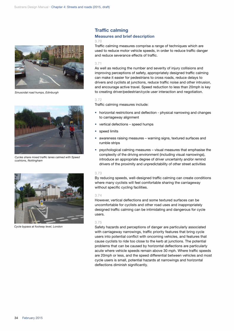
Traffic calmingMeasures and brief description 3.70Traffic calming measures comprise a range of techniques which are used to reduce motor vehicle speeds, in order to reduce traffic danger and reduce severance effects of traffic.
3.71As well as reducing the number and severity of injury collisions and improving perceptions of safety, appropriately designed traffic calming can make it easier for pedestrians to cross roads, reduce delays to drivers and cyclists at junctions, reduce traffic noise and other intrusion, and encourage active travel. Speed reduction to less than 20mph is key to creating driver/pedestrian/cycle user interaction and negotiation.
3.72Traffic calming measures include:
• horizontal restrictions and deflection - physical narrowing and changes to carriageway alignment
• vertical defections – speed humps
• speed limits
• awareness raising measures – warning signs, textured surfaces and rumble strips
• psychological calming measures – visual measures that emphasise the complexity of the driving environment (including visual narrowings), introduce an appropriate degree of driver uncertainty and/or remind drivers of the proximity and unpredictability of other street activities
3.73By reducing speeds, well-designed traffic calming can create conditions where many cyclists will feel comfortable sharing the carriageway without specific cycling facilities.
3.74However, vertical deflections and some textured surfaces can be uncomfortable for cyclists and other road uses and inappropriately designed traffic calming can be intimidating and dangerous for cycle users.
3.75Safety hazards and perceptions of danger are particularly associated with carriageway narrowings, traffic priority features that bring cycle users into potential conflict with oncoming vehicles, and features that cause cyclists to ride too close to the kerb at junctions. The potential problems that can be caused by horizontal deflections are particularly acute where vehicle speeds remain above 30 mph. Where traffic speeds are 20mph or less, and the speed differential between vehicles and most cycle users is small, potential hazards at narrowings and horizontal deflections diminish significantly.
Sinusoidal road humps, Edinburgh
Cycles share mixed traffic lanes calmed with Speed cushions, Nottingham
Cycle bypass at footway level, London

35February 2015
Sustrans Design Manual • Chapter 4: Streets and roads (2015, draft)
Benefits3.76By reducing inappropriate vehicle speeds, traffic calming can:
• reduce the incidence and severity of collision injuries involving all road users
• improve perceptions of safety and reduce traffic noise and other discomfort for road users and residents
• in some circumstances, reduce traffic volume, by diverting traffic onto more appropriate routes. Area-wide 20mph limits may help to reduce total car trips
• enable provision of cycle routes on roads where separate provision for cycling is not feasible or desirable
• enable people, including children, to reclaim streets as social places where walking, cycling and play can flourish
• increase capacity at junctions and help pedestrians and cycle users to cross traffic streams by encouraging more considerate driving behaviour
• create a smoother driving style with less acceleration and braking, thereby reducing fuel consumption and emissions
Horizontal restrictions and deflection3.77Horizontal restrictions and deflection measures include:
• carriageway narrowing (by footway widening, introduction of cycle lanes or car parking, hatchings or a central median) or local ‘pinch-points’ by build-outs and central refuges. Figure 3.10 shows how speed varies with carriageway width and forward visibility
• chicanes (with or without alternating priority) or other kerb changes to modify a straight carriageway alignment
• kerb line changes or hatching to create a more perpendicular intersection of conflicting traffic streams at junctions
• reduced curve radii, at junctions
3.78Horizontal deflection which reduces speeds and improves intervisibility at junctions is very beneficial to the safety of cycle users and pedestrians. On links, the following design recommendations should be followed to avoid introducing safety hazards for cyclists.
3.79At refuges and other physical narrowings where a cycle bypass is not provided:
• traffic lane widths in the range 3.1m – 3.9m (inclusive) should be avoided at refuges because this can lead drivers to take inappropriate risks to overtake cyclists. At lane widths of 3.0m or less, drivers will tend not to attempt to pass a cyclist at the narrowing. Where lane widths are 4.0m or more, overtaking can be achieved safely by most vehicles. Table 3.4 provides more detailed guidance
Table 3.4: Lane widths at pinch points, no cycle bypass
Speed limit
Lane width (m)
<5% HGV >5% HGV
20mph 2.5m max 3.0m max
30mph 4.0m min (1) 4.0m min (2)
1 3.0m if frequent traffic calming measures along route
2 Increase to 4.5m where 85%ile speeds exceed 30mph
Raised junction, Haringey
Advisory cycle lane continued through carriageway narrowing at refuge, York
(Pho
to: J
on T
oy)

Sustrans Design Manual • Chapter 4: Streets and roads (2015, draft)
36 February 2015
• if a cycle lane continues through the narrowing, it is recommended that this is at least 1.5m wide and mandatory. Where there is insufficient width to provide a 1.5m wide mandatory lane, an advisory 1.5m cycle lane should be considered, and coloured surfacing may be helpful to highlight the cycle lane (Figure 3.6). It is recommended that cycle lanes narrower than 1.5m are not used at pinchpoints
• where there is insufficient width for a motor vehicle to overtake a cyclist, consider marking a large cycle symbol centrally to encourage appropriate positioning by cyclists
3.80At refuges and other physical narrowings, where 85th percentile speeds exceed 20mph, a cycle bypass can be helpful to separate cyclists and other vehicles at the pinchpoint. Cycle bypasses may be particularly helpful at carriageway narrowings on uphill gradients; where the speed differential between cycle users and following vehicles tends to be high. Bypasses are not recommended in a downhill direction in most urban situations.
Cycle bypass design (Figure 3.7) should:
• avoid causing cyclists to deviate and avoid creating conflict with pedestrians
• be a minimum width of 1.5m minimum between kerbs or bollards
• include an exit alignment from the bypass that does not require cyclists to merge abruptly with motor vehicles
• protect the bypass from obstruction by car parking or loading, by waiting restrictions or physical measures
• include adequate drainage and avoid gully grate hazards for cycle users or pedestrians crossing at the refuge
• wherever possible allow for mechanical sweeping
3.81At features where one traffic stream must give way to the opposing traffic stream, there can be a failure to give way to cycle users. A cycle bypass should generally be provided.
3.82Isolated deflections on otherwise uncalmed roads should be avoided as this may lead drivers to take a ‘racing line’ through the feature to minimise the deflection.
3.83Centre of carriageway hatchings should generally be avoided, except where these are needed to protect a right turn lane or refuge. Hatchings tend to deflect vehicles towards the nearside kerb and more directly into conflict with cycle users in the secondary position. Hatchings can also increase traffic speeds by providing separation from oncoming traffic.
2m m
in
1.5m
min
1.5m
(min
)
Figure 3.6: Cycle lane past central refuge
avoid 3.1 to 3.9m
Not to scale
Advis
ory c
ycle
lane
Speed cushion (optional)
1.5
min
at t
raffi
c is
land
Figure 3.7 Bypass at pinch point

37February 2015
Sustrans Design Manual • Chapter 4: Streets and roads (2015, draft)
Vertical deflection3.84Vertical deflections comprise road humps, speed cushions, speed tables and raised entry treatments at side roads. In England and Wales, vertical deflections are regulated by The Highways (Road Humps) Regulations, 1999 (Statutory Instrument 1999 No. 1025).
3.85Cyclists are susceptible to being destabilised by abrupt changes in road surface level, particularly where they are also cornering or braking. For this reason, the following traffic calming features should be avoided on cycle routes:
• rumble-strips and ‘thumps’ (where rumble strips are used, a gap of 1.5m should be provided between the kerb and feature)
• humps with vertical upstands or steep ramps
• ramps with bumpy or slippery surfacing
3.86The following design recommendations will help to reduce vehicle speeds and minimise discomfort or hazards for cyclists:
• sinusoidal humps and sinusoidal ramps to tables and entry treatments should be used on cycle routes as they allow cyclists to maintain speed and are much more comfortable than ramps with sharp ramp transitions. For a level change of 50mm or less, a sinusoidal profile is not required for the ramp. Sinusoidal road hump design is illustrated in Figure 3.8. If a sinusoidal profile is not provided, a tapered hump should provide a minimum 1.2m gap between kerb and feature
• linear ramp gradients should normally be between 1 in 10 and 1 in 20, although the legal maximum is 1 in 6. Where there are higher vehicle flows, then flatter gradients and lower tables, or sinusoidal ramps may be more appropriate
• ramps should be constructed from asphalt and where possible should not be positioned where cyclists are cornering
• vertical upstands should be avoided altogether (the legal maximum is 6mm). It is recommended that the new surface of the ramps is continued 500mm beyond the ramp into the existing surface to produce a smoother transition
• speed cushions should be carefully designed to ensure they are effective speed deterrents (see LTN 01/07), while also minimising the necessity for cyclists to change their line of travel which can cause conflict with motorists; a 1.5m gap between kerb and feature is desirable, 1.2m as minimium (Figure 3.9)
• the impacts on cyclists of car parking adjacent to speed cushions should be considered
1.2m
pre
ferr
ed
Road hump with bypass
.925m .925m .925m .925m
50mm 50mm100mm
Sinusoidal road hump
Sinusoidal road hump cross section (preferred geometry for vertical dimension)
Edge of carriageway markings
Figure 3.8 Road humps
1.2m min at cushion
Figure 3.9 Speed cushion

Sustrans Design Manual • Chapter 4: Streets and roads (2015, draft)
38 February 2015
Street design3.87Driver behaviour is influenced by the character of the whole street, and by the other activities taking place, as well as by the nature of the carriageway. Features that make the driving environment appear less predictable will reduce the speed at which drivers feel comfortable that they can control their environment, and can significantly reduce traffic speeds. The principles underlying this approach are detailed in Chapter 3: Placemaking. Such street design measures include:
• reduced street width
• reduced lane widths (see Figure 3.11)
• reduced forward visibility combined with sightlines that emphasise the non-movement (place) functions of the street
• side road entry treatment (see Fig 3.12)
• removal of lane markings (particularly centre lines) and some other signs and road markings
• changes in priority (see Fig 3.13)
• variation in carriageway materials, colour and patterns, particularly where these are not orthogonal to the carriageway or are curved
• the amount of greenery and the sense of enclosure given by the buildings
• presence of active frontages
• high levels of pedestrian movements and formal and informal pedestrian crossings
• high levels of cycle use
• layout of car parking (see Fig 3.14)
3.88Figure 3.10 shows how speed varies with carriageway width and forward visibility.
3.89Street design is the preferred means of reducing speeds for most circumstances, particularly for cycle routes on quiet streets. Psychological calming measures can contribute to the appearance of a street and facilitate place functions and do not cause the acceleration and deceleration or physical discomfort, vibration and noise that are associated with some physical calming measures. Most psychological techniques can also be applied on higher speed roads or in combination with cycle lanes or physical traffic calming.
3.90Some street design measures are only suitable at very low speeds (generally below 20mph). These include:
• de-segregation of pedestrian and vehicle surfaces
• removal of signal or priority control at junctions
3.91‘Shared space’ treatment applies these techniques extensively to reduce traffic speeds to less than 20mph, typically as part of public realm enhancements. Shared space techniques are described in a following section.
Figure 3.10 the relationship between carriageway width, forward visibility and speed (from Manual for Streets)

39February 2015
Sustrans Design Manual • Chapter 4: Streets and roads (2015, draft)
.5m
.5m
.5m
2 - 2.5m
2 - 2.5m
0.5m contrasting over-run strip (flush)
Low median strip
.5m
Figure 3.11 Visual narrowing
Measures to consider:• reduced width• tight radii• raised crossing• contrasting surface
Figure 3.12 Side road entry
treatment
Figure 3.14 Layout of car parking
Figure 3.13 Changed priority
Not to scale

Sustrans Design Manual • Chapter 4: Streets and roads (2015, draft)
40 February 2015
Other considerations 3.92Decisions on whether and how to implement traffic calming must take account of the requirements of emergency services and bus operators. Guidance is provided in LTN 1/07: Traffic Calming (DfT, 2008) and TfL note BP2/05: Traffic calming measures for bus routes, Transport for London, 2005.
3.93Additional guidance is available in the following Welsh Active Travel Design Guidance Design elements:
• DE039 Side road entry treatment
• DE040 Blended side road entry treatment
Cycle symbol (Diagram 1057) in centre of traffic lane at carriageway narrowing, London
20mph limit area, Bristol
Residential street traffic calmed by removal of centre line and positioning parking on alternating sides of carriageway, Wokingham
Removal of centreline and trees planted in the carriageway create informal traffic calming on a radial cycle route into central Bristol
Cycle bypass at chicane, Bristol (left) and Shrewsbury (right). Note the bypass width is less than the recommended 1.5m minimum in both cases and would not accommodate a cycle trailer)
Entry treatment, London
Changed priority, London
Phot
o: J
on T
oy

41February 2015
Sustrans Design Manual • Chapter 4: Streets and roads (2015, draft)
Cycling in mixed traffic in 20mph limit, Cowley Road, Oxford
(pho
to: S
arah
Toy
)
Mixed Priority RoutesMeasure and brief description 3.94Mixed Priority Routes (MPR) are streets with a mix of land uses (commonly commercial and residential frontages) that also carry high levels of traffic. MPRs have important movement and place functions and need to accommodate a diverse mix of road users - pedestrians, cyclists, passenger service vehicles and passengers, motorists - and parking and deliveries. High streets with mixed traffic and diverse use are among the least safe of urban roads.
3.95Mixed Priority Route projects aim to balance these competing functions to deliver:
• public realm enhancements
• improved accessibility
• reduced traffic danger
• sufficient traffic capacity to avoid worsening congestion and air quality or traffic being displaced into inappropriate nearby streets
• economic regeneration
3.96Because Mixed Priority Routes include important destinations (e.g. high street shops and services) and are commonly direct routes in the network, it is important that cycle users are accommodated effectively, rather than diverted to avoid the traffic conditions along street.
3.97Design approaches tend to:
• reduce traffic speeds (in order to facilitate pedestrian permeability, smooth vehicle flows and reduce emissions, and enable cycle users to share the carriageway). This may include physical traffic calming and psychological calming approaches
• enhance pedestrian crossing opportunities through formal and informal crossings
• mix cyclists with other traffic
• reallocate and better utilise street space to accommodate one or more of:
• widened footways
• a median strip (to facilitate informal pedestrian crossing)
• parking or loading
• sometimes bus and/or cycle priority
• introduce entry treatment at side roads to improve pedestrian priority while retaining access
• improve cycle parking and manage car parking and loading
• enhance bus stops and information
• rationalise and renew street furniture to encourage people to dwell and reduce clutter
• introduce street trees and other soft landscaping

Sustrans Design Manual • Chapter 4: Streets and roads (2015, draft)
42 February 2015
Benefits 3.98MPR treatments offer the following benefits:
• reduced speed and dominance of motor vehicles
• direct cycle routes and enhanced cycle accessibility to local destinations
• reduced road casualities, improved perception of safety; and increases in cycling and walking activity
• economic regeneration
Key design features3.99Key enhancements for cycle users include:
• low speeds to enable cycle users to share the carriageway comfortably and safely
• filtered permeability at side roads, including cycle right turn lanes where needed
• advanced stop lines
• cycle-friendly traffic lane widths (avoiding lane widths in the range 3.1m to 3.9m)
• cycle lanes where queuing traffic would otherwise delay cycle users
• enhanced cycle parking at frequent intervals
• cycle-friendly traffic calming (see preceding section on traffic calming for guidance on lane widths and design of vertical deflections)
3.100A key design issue is to provide adequate lane widths for cyclists in mixed traffic (and cycle lanes to provide cycle priority where there is congestion) while delivering adequate footway widths and keeping speeds low.
3.101Mixed priority street design commonly includes changes of carriageway materials. Designs should avoid upstands and ensure surfaces are smooth (to minimise discomfort) with a high friction co-efficient to avoid slip hazards.
3.102Particular care will be needed to design for cycle users adjacent to car parking. If cycle lanes are provided, a strip 0.5m wide should be included between the cycle lanes and parking bay. Echelon parking should be avoided where possible because of vehicle reversing hazards.
Other considerations 3.103Local cycle groups should be engaged during all design stages.

43February 2015
Sustrans Design Manual • Chapter 4: Streets and roads (2015, draft)
High street calmed with shared space principles: 2.0m traffic lanes with textured margin strips, a central median, reduced kerb heights and informal pedestrian crossings, Park Lane, Poynton
Shared spaceMeasure and brief description 3.104Shared space is a design approach that seeks to reduce the dominance of motor vehicles by creating a low speed environment (less than 20mph), often without formal priority rules, in which drivers, pedestrians and cyclists can interact and negotiate with each other through eye contact.
3.105In the UK, shared space has to date been primarily focused in town centres and villages where there is likely to be a high proportion of pedestrians. Shared space design principles can be applied to links and junctions, including junctions with significant traffic flows and HGVs.
3.106A key part of the design concept is to remove features that lead drivers to think that the road environment is predictable. By narrowing traffic lanes, removing signs and lines, omitting formal priority at junctions, reducing demarcation between carriageway and footways and introducing a range of other psychological traffic calming techniques, shared space designs encourage drivers to slow down and engage with their surroundings and other road users.
3.107The resulting smooth, low speed driving style makes drivers much more willing to give way to pedestrians and can also reduce traffic queues and delays at junctions. It reduces the intrusiveness of traffic in public spaces by improving pedestrian accessibility, by reducing traffic noise and danger, and reducing the space needed to accommodate movement of vehicles.
3.108Shared space environments can be convenient and attractive to cycle users. Although many schemes include narrow lane widths, cyclists can mix comfortably with traffic because of the very low speeds. By reducing stop-start traffic conditions, shared space can reduce cycling journey times and may improve cycling accessibility by reinstating two-way working. However, shared space designs do not generally provide an opportunity to include cycle lanes or tracks to avoid any remaining traffic queues. Successful designs need to ensure that the needs of visually impaired pedestrians are addressed.
3.109Benefits • reduced traffic speeds with neutral or positive effect on journey time
• improved road safety and perception of safety
• can improve cycling and pedestrian accessibility and journey times
• enhanced attractiveness and comfort of cycle routes and public spaces
• offers many of the benefits for pedestrians of vehicle restricted areas and enables access by cycle users in situations where excluding traffic is not deliverable
• increased cycle parking can be accommodated using reallocated space
• can improve air quality by smoothing driving style and reducing delays at traffic signals

Sustrans Design Manual • Chapter 4: Streets and roads (2015, draft)
44 February 2015
• removal of guard rail and delays at signalised crossings and junctions
Key design features3.110There is no standard design for shared space; a key element of the approach is that designs should reference the buildings and street space in which traffic moves.
3.111Speed reduction to less than 20mph is key to creating driver/pedestrian/cycle user interaction and negotiation.
3.112Other common elements in the design palette include:
• gateway features which help to mark the change in street character
• narrow traffic lanes (2.0m wide running surface with 0.5m wide margin strips) - see Figure 3.11
• single lane entries at junction – these can replace multi lane entries at signalised junctions without loss of capacity
• removal of formal priority markings or traffic signals and removal of signage – in low speed environments this encourages drivers to engage with their surroundings and other road users
• informal pedestrian crossing points and use of a median strip to enable pedestrians to cross at all locations along the streets
• re-establishing two-way working and revoking prohibited manoeuvres at junctions
• psychological traffic calming including changes of material, non-rectilinear and curved features
• desegregation of pedestrian and vehicle surfaces. A level surface is a particular form of shared space, where the street surface is not physically divided by kerb or level difference into areas for particular users. These need careful design if they are to work for all users. Disabled people with physical, sensory and cognitive impairments all find such streets difficult to use and many avoid such areas. There needs to be a distinct, detectable route for vulnerable pedestrians, though this does not prevent other pedestrians who wish to from sharing the central part of the space. Currently the only confirmed demarcation is a footway raised above the carriageway with a kerb upstand, although other designs are being trialled
High street calmed with shared space principles: removal of centre line, reduction of carriageway width and reduction of kerb heights, Stonehouse, Gloucestershire

45February 2015
Sustrans Design Manual • Chapter 4: Streets and roads (2015, draft)
3.113The following design elements should be addressed to ensure shared space schemes work successfully for cycle users:
• designs should increase accessibility for cycle users
• gateways should not create pinch-points for cycle users, particularly where vehicle speeds may exceed 20mph on the approaches to shared space areas (see guidance on widths at refuges above)
• cycle routes through shared spaces need to be clear and legible whilst not detracting from the shared space principles
• surfaces should be smooth with a high friction co-efficient
• designs avoid vertical upstands across the route used by cyclists (e.g. at informal crossing points). Designs may include upstands to define the edge of a vehicular/cycling route
• street furniture, planting and seating should not obstruct or create hazards for cyclists
• cycle parking needs to be provided close to trip generators and at frequent intervals
• cycle users should be engaged throughout scheme design stages
Other considerations 3.114Drainage must be well designed to avoid ponding especially in areas with level surfaces.
Quiet streetsMeasure and brief description 3.115Quiet streets (branded Quietways in London) is a term given to urban cycling routes on streets with low traffic volumes (less than 3000 vehicles per day) and low traffic speeds, but which nevertheless offer a direct and convenient route. Quiet streets are particularly suitable for new and less confident cyclists and complement provision on busier corridors. A quiet streets network should provide for longer cycle journeys between key destinations; as well as short local trips.
3.116Quiet streets are typically residential streets used by other vehicles for access only and minimal intervention will be needed along much of the route. Quiet streets must maintain route continuity for cycling and targeted provision will be required to tackle physical barriers, such as difficult junctions, crossings of busy roads and one way streets. Traffic free sections through parks and other green corridors and sections of cycle track alongside busier roads will form important links in a quiet streets network.
3.117Quiet streets should minimise diversions away from desire lines and delays at junctions and should be implemented end-to-end; not piecemeal.
Traffic calmed urban quiet street, Great Suffolk Street, Southwark

Sustrans Design Manual • Chapter 4: Streets and roads (2015, draft)
46 February 2015
Not to scale
Crossing of busy road, Bristol (Note: whilst cyclists do not have priority on a zebra crossing, they are permitted to use them provided that cycle tracks are provided each side (see Sustrans Technical Information Note 17)
Radius reduced, Bristol
Section of closed road
Changed priority, London
One-way southbound with contraflow cycling, Bristol
Point closure, London
Surface treatment (Cycle Street), The Netherlands
Figure 3.16 Examples of quiet streets treatment
One-way northbound with contraflow cycling
Cycle logos on carriageway
Raised table

47February 2015
Sustrans Design Manual • Chapter 4: Streets and roads (2015, draft)
Benefits 3.118Quiet streets provide attractive and comfortable cycling conditions, and will be safe and perceived to be safe. They will help to attract new and less confident cycle users, including children, and will also be used by experienced cycle users for many journeys, where they are direct.
3.119Much of a quiet streets network will be on road and will be cost-effective to implement. The measures used to restrict inappropriate through traffic and maintain low speeds will benefit residents.
3.120Key design features • a quiet streets network should provide for cycling desire lines between
journey attractors and/or run parallel to established main road cycle routes and public transport routes. They will generally include direct radial and orbital routes across larger towns and cities
• quiet streets should be direct and minimise delays by prioritising cycle movements. Safety features (e.g. access controls, staggered barriers) that make cycling inconvenient should not be used or retained
• quiet streets will predominantly comprise roads with low traffic flows (less than 3000 vehicles per day) and very few HGVs. Traffic speeds will be 20mph or less. In most cases, cyclists will share the carriageway with other vehicles
• where traffic volume levels exceed 3000 vehicles, filtered permeability and traffic calming measures can be used to achieve and maintain low traffic volumes and speeds
• traffic free routes through parks and other open spaces can form attractive links in the network and may provide valuable shortcuts. However, personal security considerations may necessitate alternative connections to maintain a viable 24/7 network
• sections along busy roads should be kept to a minimum and should provide kerb segregation from traffic
• quiet streets should avoid or comprehensively address significant collision hotspots and major junctions, particularly large roundabouts
• routes should minimise points of potential conflict with oncoming and crossing traffic, parked vehicles and loading activity
• cycle symbols to diagram 1057 can be used to sign the continuity of cycle routes and indicate the correct positioning for cycling within the carriageway; in so doing they also raise motorists’ awareness of cyclists, encouraging them to give cyclists space
Other considerations3.121Pedestrian facilities should not be negatively affected by quiet streets.
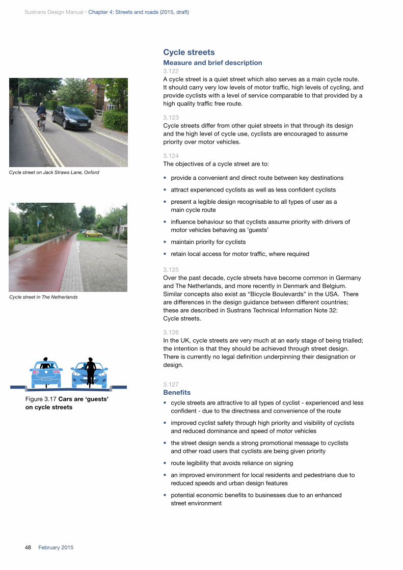
Sustrans Design Manual • Chapter 4: Streets and roads (2015, draft)
48 February 2015
Cycle streetsMeasure and brief description 3.122A cycle street is a quiet street which also serves as a main cycle route. It should carry very low levels of motor traffic, high levels of cycling, and provide cyclists with a level of service comparable to that provided by a high quality traffic free route.
3.123Cycle streets differ from other quiet streets in that through its design and the high level of cycle use, cyclists are encouraged to assume priority over motor vehicles.
3.124The objectives of a cycle street are to:
• provide a convenient and direct route between key destinations
• attract experienced cyclists as well as less confident cyclists
• present a legible design recognisable to all types of user as a main cycle route
• influence behaviour so that cyclists assume priority with drivers of motor vehicles behaving as ‘guests’
• maintain priority for cyclists
• retain local access for motor traffic, where required
3.125Over the past decade, cycle streets have become common in Germany and The Netherlands, and more recently in Denmark and Belgium. Similar concepts also exist as “Bicycle Boulevards” in the USA. There are differences in the design guidance between different countries; these are described in Sustrans Technical Information Note 32: Cycle streets.
3.126In the UK, cycle streets are very much at an early stage of being trialled; the intention is that they should be achieved through street design. There is currently no legal definition underpinning their designation or design.
3.127Benefits • cycle streets are attractive to all types of cyclist - experienced and less
confident - due to the directness and convenience of the route
• improved cyclist safety through high priority and visibility of cyclists and reduced dominance and speed of motor vehicles
• the street design sends a strong promotional message to cyclists and other road users that cyclists are being given priority
• route legibility that avoids reliance on signing
• an improved environment for local residents and pedestrians due to reduced speeds and urban design features
• potential economic benefits to businesses due to an enhanced street environment
Figure 3.17 Cars are ‘guests’ on cycle streets
Cycle street on Jack Straws Lane, Oxford
Cycle street in The Netherlands

49February 2015
Sustrans Design Manual • Chapter 4: Streets and roads (2015, draft)
3.128A cycle street can have the following advantages compared to a traffic free route:
• less space required to accommodate cycle users and other vehicles
• less complexity and greater accessibility compared to separate provision
• better personal security
3.129Key design features • the street design should encourage cyclists to adopt the primary riding
position and assume priority, with drivers of motor vehicles behaving as ‘guests’. The available width should discourage drivers from overtaking
• cyclists should have priority at junctions and on links. The street must be recognisable as a cycle street, including for drivers approaching on side roads
• a cycle street should carry at least 1000 cyclists per day, including forecast growth
• cycle users should potentially outnumber motor vehicles, preferably outnumbering them by a factor of two to one
• cycle streets should carry no more than 2000 motor vehicles per day, accessing local destinations, with minimal use by large vehicles
• traffic speeds should be low; generally below 20mph
• cycle streets can be one way or two way for motor traffic
• the length over which a car has to follow a cyclist should be limited to 400m
• cycle streets may extend continuously for more than 400m, incorporating filtered permeability techniques to divert motor traffic from the cycle route at intervals. Common techniques include road closures with cycle gaps, or alternating one-way orders with contraflow cycling
• designs should minimise nuisance caused by parked vehicles. Where parking or loading is permitted, the design should take account of variation in use of the kerbside space at different times of day and the effect on user behaviour at times when parking/loading space is unoccupied
• wherever possible, the design should include public realm improvements and address any local concerns that may be resolved by the scheme
3.130Other considerations If a cycle street is on hill, cyclists travelling in the uphill direction will travel more slowly and may not adopt the primary position.

Sustrans Design Manual • Chapter 4: Streets and roads (2015, draft)
50 February 2015
Home zonesMeasure and brief description 3.131Home zones are residential streets in which the road space is shared on equal terms between drivers of motor vehicles and other road users to achieve a balance between vehicle movement and the wider needs of the community. These wider needs include safe and convenient movement by pedestrians and cycle users, adequate parking and cycle parking, and space for children to play and for other social activities. There is also potential to incorporate planting and communal bin areas.
The Dings home zone, Bristol
3.132Within a home zone, design features of the highway and wider streetscape should deliver self-enforcing low speeds (less than 20mph) and indicate to drivers that they are sharing space with other legitimate activities so that they regulate their driving behaviour. Home zone design commonly incorporates shared space concepts described in a preceding section.
3.133The concept originated in The Netherlands as the Woonerf. In England and Wales, local authorities can implement home zones under Section 268 of the Transport Act 2000 (HMSO, 2000) or in Scotland using the Transport (Scotland) Act 2001 and The Home Zones (Scotland) (No 2) Regulations 2002.
3.134Benefits • home zones are intended to change the role and function of a street.
The layout discourages through traffic and reduces vehicle speeds to less than 20mph, thereby facilitating and encouraging use of residential streets for cycling, walking, play and social activities
• the very low speeds and changes in driver behaviour improves road safety and the perception of safety; creating conditions in which children can play and cycle unsupervised, thereby fostering important skills and healthy lifestyles

51February 2015
Sustrans Design Manual • Chapter 4: Streets and roads (2015, draft)
• essential vehicle access can and should be maintained
• increased street activity helps to improve personal security and build community cohesion
• public realm enhancements can help regenerate streets and neighbourhoods
Key design features 3.135A home zone will generally include a combination of the following features:
• gateway features
• a level surface (see section on Shared Space)
• indirect routes for traffic
• junction priorities removed
• areas of planting
• seats or play equipment
• appropriate signage
3.136Key considerations include:• cycle lanes and other cycle specific facilities will very rarely be
necessary in home zones, with the exception of filtered permeability at access points and cycle parking
• Home zones should normally enable two-way traffic. Where one-way orders are in place, two-way cycling should be permitted using “Except cycles” signs at entry points; contra-flow lanes will not be necessary
• vertical traffic calming features are generally not required to achieve very low speeds in home zones
• designs should avoid horizontal deflection or narrowings that would create hazardous or intimidating conditions for cyclists
• Home zones will often include a pedestrian-only space or route for vulnerable users, particularly where the design includes level surfaces
3.137Other considerations• Home zones can be cost effective at a neighbourhood level in new
build housing developments. However home zones have proved expensive to retro-fit in existing streets
• surfaces should be smooth with a high friction co-efficient
• drainage must be well designed to avoid ponding especially in areas with level surfaces. One solution is sustainable drainage systems (SuDS) which were integrated in The Dings home zone, Bristol (picture previous page)
Home zone with relatively low cost treatment including flat-topped humps with sinusoidal ramps, Wilberforce Avenue, York
(pho
to: J
on T
oy)

Sustrans Design Manual • Chapter 4: Streets and roads (2015, draft)
52 February 2015
Community street designMeasure and brief description 3.138Community street design is a Sustrans community-led initiative that works with residents and other partners to create high quality urban improvements that promote and facilitate sustainable travel. These projects help communities to make their neighbourhoods safer and more pleasant places to live and travel and to create spaces suitable for people to meet, socialise, and play.
3.139Community street design can be applied in different settings:
• residential street design - often referred to as DIY streets. The technique can be applied to individual streets or neighbourhoods to provide an affordable, community-led alternative to home zones. Typically this involves addressing traffic speed and/or volume, rat-running, problem parking, as well as delivering activities to encourage sustainable travel behaviour and more social use of streets as public spaces
• mixed-use and high street design. The community-led design approach can be adapted to tackle the more complex issues and needs of mixed-use and high streets. These focus on engaging the full range of stakeholders for these spaces and creating innovative solutions to satisfy a wide range of use needs. This may include the creation of ‘pocket places’
• schools - active school neighbourhoods (ASNs) are neighbourhood-wide initiatives, which focus on school catchments
• villages - community-led initiatives to address traffic speed/volume issues in villages with sensitivity to the rural nature of the surroundings
Benefits 3.140Community street design can deliver:
• traffic speed and volume reduction
• safer more attractive neighbourhoods for cycling and walking, for play and other social activities
Selective junction treatment in DIY streets project, Haringey

53February 2015
Sustrans Design Manual • Chapter 4: Streets and roads (2015, draft)
• connections from where people live to other cycling infrastructure; key routes are identified through community engagement
• improved accessibility and way-finding
• encouragement of cycling through free cycle training and bicycle maintenance
• safer environments which give residents confidence to let their children learn to cycle on roads
3.141Advantages of the community street design approach include:
• project design is flexible and is steered primarily to residents’ aspirations for improvements in their area
• community-led improvements help residents take ownership of changes in their neighbourhoods. This can facilitate acceptance of measures to restrict or reduce motor vehicle usage
• community street design projects are more affordable compared with home zones; enabling improvements across larger project areas
Key design features 3.142Community street design projects typically include:
• traffic speeds reduced with 20mph zones or limits, and Innovative ‘psychological’ traffic calming measures
• filtered permeability – facilitating cycling and walking access while restricting through traffic
• cycle parking
• combining cycling provision with public realm enhancements e.g. planters combined with cycle parking
• walking and cycling audits which help to identify cycling issues to inform designs
3.143Other considerations • cycle training can be offered to residents and is useful on completion
of projects by navigating changes to the road layout
• bicycle maintenance offered at community workshops helps draw cyclists into projects such as DIY streets
• cycling and walking maps centred around project neighbourhoods
• drainage and materials considerations
• on-street bicycle work stations and cycle pumps
Beechcroft DIY street, Oxford
(Pho
to: S
arah
Toy
)
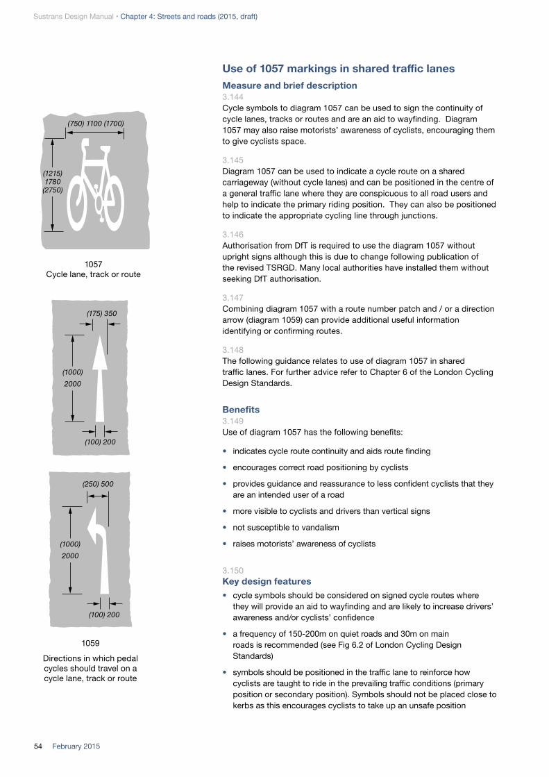
Sustrans Design Manual • Chapter 4: Streets and roads (2015, draft)
54 February 2015
Use of 1057 markings in shared traffic lanesMeasure and brief description 3.144Cycle symbols to diagram 1057 can be used to sign the continuity of cycle lanes, tracks or routes and are an aid to wayfinding. Diagram 1057 may also raise motorists’ awareness of cyclists, encouraging them to give cyclists space.
3.145Diagram 1057 can be used to indicate a cycle route on a shared carriageway (without cycle lanes) and can be positioned in the centre of a general traffic lane where they are conspicuous to all road users and help to indicate the primary riding position. They can also be positioned to indicate the appropriate cycling line through junctions.
3.146Authorisation from DfT is required to use the diagram 1057 without upright signs although this is due to change following publication of the revised TSRGD. Many local authorities have installed them without seeking DfT authorisation.
3.147Combining diagram 1057 with a route number patch and / or a direction arrow (diagram 1059) can provide additional useful information identifying or confirming routes.
3.148The following guidance relates to use of diagram 1057 in shared traffic lanes. For further advice refer to Chapter 6 of the London Cycling Design Standards.
Benefits 3.149Use of diagram 1057 has the following benefits:
• indicates cycle route continuity and aids route finding
• encourages correct road positioning by cyclists
• provides guidance and reassurance to less confident cyclists that they are an intended user of a road
• more visible to cyclists and drivers than vertical signs
• not susceptible to vandalism
• raises motorists’ awareness of cyclists
3.150Key design features• cycle symbols should be considered on signed cycle routes where
they will provide an aid to wayfinding and are likely to increase drivers’ awareness and/or cyclists’ confidence
• a frequency of 150-200m on quiet roads and 30m on main roads is recommended (see Fig 6.2 of London Cycling Design Standards)
• symbols should be positioned in the traffic lane to reinforce how cyclists are taught to ride in the prevailing traffic conditions (primary position or secondary position). Symbols should not be placed close to kerbs as this encourages cyclists to take up an unsafe position
(1215) 1780 (2750)
(1000)2000
(175) 350
(100) 200
(250) 500
(1000)2000
(100) 200
(750) 1100 (1700)
1057 Cycle lane, track or route
1059
Directions in which pedal cycles should travel on a cycle lane, track or route

55February 2015
Sustrans Design Manual • Chapter 4: Streets and roads (2015, draft)
• Diagram 1057 markings should be orientated in the direction of cycle flow
• Diagram 1057 markings should be considered at the following locations along a cycle route:
• along quiet streets, including cycle contra-flow sections where no lane is marked
• on sections of main road cycle route where it is not feasible or appropriate to provide delineated facilities
• on heavily trafficked roads across side-road junctions
• across busy junctions indicating the advised position and line of travel for cyclists
• to identify a drop kerb where cyclists may leave the carriageway
• where cyclists’ line of travel may be interrupted, for example by vehicles using bus stops or loading or parking bays
• advanced stop line reservoirs
• staggering symbols in each direction along a route will reduce the effective distance between them on single one or two-lane carriageways, indicating route continuity without creating visual clutter
• over-use of diagram 1057 markings should be avoided, particularly in sensitive streetscape areas
• Diagram 1057 markings must conform to DfT’s working drawings
3.151Other considerations • symbols may be used in bus lanes if appropriate
• pre-formed thermoplastic symbols should be used to avoid unacceptable road markings
• maintenance liability should be considered, particularly in areas of high wear. Thermoplastic markings break up quickly when used on block paving
Diagram 1057 indicating cycle route across a junction, London
Diagram 1057 indicating cycle riding position where traffic lane is narrowed by parking, London
Diagram 1057 with direction arrow (diagram 1059)
Diagram 1057 with a route number patch

Sustrans Design Manual • Chapter 4: Streets and roads (2015, draft)
56 February 2015
4. Reallocation of space between usersOverview4.1The preceding sections describe techniques for reducing traffic speed and volume and modifying driver behaviour to the extent that cycle users can share the carriageway with other vehicles.
4.2This section describes the types of designated infrastructure for cycle users, separate from other vehicles, which can be created by reallocating space from other street/road functions.
4.3Section 2 above provides guidance on the range of factors that influence which type of provision for cyclists will be most appropriate. Traffic volume and speed are key determinants (but not the only consideration) of the types of provision that will be appropriate on a link. Figure 2.1 illustrates how traffic volume and speed may influence the decision on the need to segregate cyclists from other traffic, and the types of provision that are likely to be appropriate at different speed-flow conditions. The threshold values are intended to reflect the needs of a novice cyclist who is trained to National Standards/Bikeability Level 2.
4.4Three categories of separate cycling provision can be introduced by reallocating space. These are:
• cycle lanes: advisory or mandatory cycle lanes and bus/cycle lanes
• physical segregation from traffic: light segregation and ‘hybrid’ (stepped) tracks
• physical segregation from traffic with a verge or margin strip: cycle-only tracks, segregated shared use tracks or unsegregated shared use tracks
4.5All three categories of cycling provision can be implemented either by reallocating carriageway space or converting the verge and/or footway to allow cycle use. Wherever possible, reallocation of carriageway space should be selected in preference to taking space from the verge or footway. Reallocating carriageway space is often achievable at low cost and can contribute to traffic demand management, without taking space from pedestrians or other non-movement activities
4.6In some situations, as an interim measure, it may be appropriate to provide more than one form of cycling provision on the same route or closely adjacent routes, in order to cater for different types of cyclist who may place different value on separation from traffic and the directness usually achieved by staying on the carriageway.
4.7Reallocation of carriageway space will commonly involve one or more of the following:
• removal of traffic lanes
• reduced width of traffic lanes
• removal of the centre line
• removal of car parking

57February 2015
Sustrans Design Manual • Chapter 4: Streets and roads (2015, draft)
Narrowing of traffic lanes/ removal of centre line, Cambridge
Removal of traffic lane to provide cycle track, Bristol
Removal of traffic lanes to provide cycle lanes, Hull
2.0 2.06.0m - 7.3m
foot
way
Foot
way
Fig 4.3 Removal of traffic lanes to provide cycle lanes
2m 6m
Remove centre line for widths below 5.5m
1.5 1.55m
Afte
rBe
fore
Fig 4.1 Narrowing of traffic lanes
7.3m 7.3m
Afte
rBe
fore
3.65m 4m3.65m
Segregated two-way cycle track
Fig 4.2 Removal of traffic lane to provide cycle track
Afte
rBe
fore
Single carriageway Dual carriageway11.0 - 14.5m
Not to scale
4.8Figures 4.1 to 4.3 provide examples of some of the approaches that can be used.
4.9Where cycle specific infrastructure is identified to be appropriate, designers are recommended to consider if some speed and /or volume reduction should also form part of the design solution. Speed and volume reduction can deliver additional safety benefits (real and perceived), enhance user comfort, facilitate pedestrian and cycle permeability at junctions and crossings, reduce movement space requirements, and support place functions.

Sustrans Design Manual • Chapter 4: Streets and roads (2015, draft)
58 February 2015
Mandatory cycle lane within bus lane, Blackfriars Bridge, London
Advisory cycle lane in uphill direction only, Bristol. Note that the cycle lane width is less than the 1.5m recommended minimum and does not enable cycle users to overtake within the lane.
Cycle lanesMandatory and advisory cycle lanesMeasure and brief description 4.10Cycle lanes are lanes on the carriageway that are reserved either exclusively or primarily for the passage of cyclists. Cycle lanes are normally located on the left or kerb side of the road, but may be positioned between traffic lanes on the approach to and through junctions.
4.11Cycle lanes have four main functions:
• to improve cyclists’ safety, perceived safety and comfort by helping to separate cycle users from streams of other vehicles and by raising motorists’ awareness of potential cycle users, particularly at junctions
• to provide designated space for cycle users to pass queueing traffic
• to indicate cycle route continuity and mark the appropriate route for cyclists to follow through junctions
• a form of psychological traffic calming, by narrowing general traffic lanes
Where cycle lanes are appropriate4.12Cycle lanes do not provide physical protection and it is important that the traffic regime is appropriate to the presence of cyclists on the road. Cycle lanes are suitable for roads where the 85th percentile speed is 40mph or less and traffic flows are low, but their use should be limited to lower speed roads where traffic flows exceed 3000 vehicles per day (Figure 2.1). Cycle lanes are generally used in situations where most cycle users will find it difficult to assume the primary riding position.
4.13Cycle lanes will generally not be necessary where speeds are 20mph or less, except where traffic flows exceed 6000 vehicles per day and cycle lanes can help cyclists bypass queues.
4.14The design of cycle lanes requires careful attention to turning movements of both cyclists and other traffic.
4.15Cycle lanes are only useful when clear of car parking and loading activity and should not be provided where they are regularly obstructed by parking and loading. Careful attention to this design issue is required especially in town centres and around schools.

59February 2015
Sustrans Design Manual • Chapter 4: Streets and roads (2015, draft)
Types of cycle lane: mandatory and advisory4.16There are two types of cycle lane:
• mandatory lanes are marked with a continuous white line (diagram 1049) and require a Traffic Regulation Order which prohibits motor vehicles from driving or parking in them during the hours of operation. There can be exceptions, such as for emergency service vehicles and access to private driveways. A variant of this type of lane is the shared bus/cycle lane (sometimes also allowing taxis and/or motorcycles)
• advisory lanes are marked with a broken white line (diagram 1004) which indicates that other vehicles should not enter unless it is safe to do so
4.17Mandatory lanes provide greater protection for cyclists and should be used where possible. Mandatory lanes should operate at all times unless there are clearly justified reasons not to do so.
4.18Contraflow cycling can be achieved with mandatory or advisory cycle lanes, or no lane. The advantages of each approach and contraflow signing requirements are described in Section 3.
Benefits4.19Mandatory and advisory cycle lanes can:
• improve cyclists’ safety, perceived safety and comfort and signal that cyclists are valued road users by designating space for cycle users
• increase motorists’ awareness of potential cycle users
• create space for cycle users to pass queueing traffic and traffic calming features
• indicate cycle route continuity and mark the appropriate route for cyclists to follow through a junction
• reduce traffic speed by narrowing general traffic lanes
• be supported by parking, loading and waiting restrictions enforced by civil enforcement officers
• facilitate contraflow cycling on one-way streets
4.20Benefits of mandatory cycle lanes:
• mandatory cycle lanes of adequate width give better protection to cyclists on highways than advisory lanes, as the solid white line is supported by a traffic order and is less likely to be crossed by motor vehicles
• mandatory lanes provide for exclusive use by cyclists during hours of operation (generally at all times), with exemptions in specific cases
• can be enforced by the police

Sustrans Design Manual • Chapter 4: Streets and roads (2015, draft)
60 February 2015
4.21Benefits of advisory cycle lanes:• advisory cycle lanes can be useful in circumstances where a
carriageway is not wide enough to permit full width mandatory cycle lanes, resulting in occasional motor vehicles entering the cycle lane
• can be used where cycle lanes cross side road junctions
• can be useful to indicate routes through a large or complex junction
Key design features 4.22Mandatory and advisory cycle lanes share the following features:
• minimum 1.5m width in 30mph limits
• 2.0m where speed limit is 30mph and cycle flow exceeds 10% of total traffic
• 2.0m min where cycle lane is positioned between traffic lanes (e.g. where there is strong vehicle left turning movement)
• minimum 2.0m width in 40mph limits
• 2.0m wide cycle lanes (1.5m minimum) plus 1.0m wide dividing strip (0.5m min) alongside parking/loading bays
• cycle lane width can be reduced to 1.2m on nearside approach to ASL
• cycle lane entry taper 1:10 (diagram 1009); exit taper 1:5
• coloured surfacing and cycle symbols (diagram 1057) should be considered to highlight cycle lanes at the following locations
• feeder lanes to advance stop lines
• across side roads
• contraflow lanes
• where there is a tendency for vehicles to encroach in to the cycle lanes e.g. left hand bends and at carriageway narrowings
• lanes beside parked cars
• any other areas of potential conflict with motor vehicles
• further guidance on correct signing and road markings can be found in the Traffic Signs Manual, Chapter 3: Regulatory Signs (2008) and Chapter 5: Road Markings (2003)
4.23Key design features for mandatory cycle lanes
• TRO required for mandatory cycle lane
• solid white delineation line 150mm wide (diagram 1049)
• the cycle road marking (diagram 1057) displayed at 50-200m intervals along the route
• vertical sign diagram 958.1 at the start of the lane and with-flow cycle lane signs (diagram 959.1) should be provided after every junction and after every 300m of unbroken cycle lane
962.1
610 (on bollard)
Mandatory contraflow cycle lane
Alternative layout: segregation at exit
967
967
962.1
1001.2
1009
1057
1004
2.5m(min 1.5)
Advisory cycle lane
2.5m(min 1.2)
956.1
959.1
1009
1057
10491057 (50-200m
intervals)
1049 must be stopped but continuing with 1010
and red surfacing
300mm stop line
200mm stop line
Mandatory cycle lane
Figure 4.4: Typical layout and signage of mandatory and advisory cycle lanes, and advanced stop line

61February 2015
Sustrans Design Manual • Chapter 4: Streets and roads (2015, draft)
7 London Cycling Design Standards, 2014
• at the end of mandatory and advisory cycle lanes, or where it is interrupted by a pedestrian crossing or junction, it is not required to install ‘END’ road markings
• mandatory lanes must be discontinued at side road junctions but the use of a short length advisory lane or Diag 1010 markings across the side road preserves continuity (advisory cycle lanes or Diag 1010 markings can also be used to maintain continuity through larger junctions)
• where there are particular problems of overrun of cycle lanes by motor vehicles, raised thermoplastic markings can be used to help deter this
• a variant of this type of lane is the shared bus/cycle lane (sometimes also allowing taxis and/or motorcycles). With-flow bus/cycle lanes are signed using a continuous white line (diagram 1049) with relevant bus lane road markings
Advisory cycle lane across side road junction with entry treatment, Cycling Superhighway 7, London
4.24Key design features for advisory cycle lanes
• bounded by broken white line (diagram 1004) 100mm wide
• the cycle road markings (diagram 1057) is displayed at intervals
• upright signs (diagram 967) placed at the start of the lane and after every break, as well as at suitable intervals on long uninterrupted lengths. In order to minimise street clutter, TfL7 recommends that diagram 967 should only be used in locations where interpretation of the cycle lane road markings is not otherwise clear and it is unlikely to be necessary in areas with a 20mph limit
• TRO not required for cycle lane but normally required for associated waiting/loading restrictions
• advisory cycle lanes are not recommended where they are likely to be blocked by parked vehicles
4.25Other considerations:
• additional protection of cycle lanes can be provided using hatched road markings or traffic islands
• substandard width cycle lanes should be avoided. Inadequate cycle lane widths can increase conflict risk because cyclists may need to ride unexpectedly out of the cycle lane to avoid surface hazards. Evidence shows that drivers pass cyclists with less clearance where there is a cycle lane

Sustrans Design Manual • Chapter 4: Streets and roads (2015, draft)
62 February 2015
* May be used where speeds are 20mph or less to avoid queuing traffic
• where width is constrained, a wider advisory cycle lane is preferable to a narrow mandatory one
• a single uphill cycle lane is preferable to a sub-standard cycle lane in both directions
• existing service covers in carriageways can be changed to durable non-slip covers made from composite material. Cycle-friendly drainage grates should be used
• where a cycle lane travels through a pedestrian crossing, no lane markings are allowed through the ‘zig-zag’ markings area, but coloured surfacing can be used
• cycle lane markings will be included in the normal road maintenance programme
Table 4.1: Key features of mandatory and advisory cycle lanes
Mandatory Advisory
Width 2.0m preferred (min if speeds over 30mph)
(1.5m minimum)
(1.2m minimum for ASL feeder lane)
2.0m preferred (min if speeds over 30mph)
(1.5m minimum)
(1.2m minimum for ASL feeder lane)
Traffic speed 20 – 40mph* 20 – 40mph*
TRO Yes No
Waiting/loading Restrictions
Not mandatory but police are unlikely to enforce so no waiting/no loading orders are generally needed to enable Council enforcement
Generally needed in urban areas
Enforceable Enforceable by the police
Not enforceable
Line demarcation 150mm solid white line (diagram 1049)
100mm or 150mm intermittent white line (diagram 1004)
Upright signs With-flow cycle lane signs, diagram 958.1 and 959.1
Diag 967 required but may change following revised TSRGD
Continue across side road junctions
No Yes
Continue through junctions
No Yes
Wide advisory cycle lane within bus lane continues across side road junction, Brighton
Coloured surfacing provides route continuity through pedestrian crossing zigzags, York
(pho
to: J
on T
oy)

63February 2015
Sustrans Design Manual • Chapter 4: Streets and roads (2015, draft)
Cycle lanes at side roadsMeasure and brief description 4.26Advisory cycle lanes should be continued across side road junctions to reinforce route continuity and help improve cycle safety. Marking a mandatory lane across side road junctions is not permitted; on routes with mandatory lanes, a short section of advisory lane or Diag 1010 markings can be used at the junction to provide continuity.
4.27It is recommended that cycle lane width be increased by 0.5m at side roads to encourage cyclists to position themselves further out from the give way or stop line, so that they can avoid vehicles nosing into the main road, and be more visible to drivers. Coloured surfacing is recommended where vehicle encroachment may occur.
4.28A side road entry treatment should also be considered as this will reduce the speed of vehicles turning into and out of the junction.
4.29Benefits • cycle lanes marked across the mouth of a side road junction can help
to raise driver awareness of cycle users through the junction
• use of coloured surfacing and diagram 1057 ‘cycle’ symbol to emphasise cycle lanes at a junction can reduce vehicle encroachment
• assists with route continuity and wayfinding
4.30Key design features • advisory cycle lane markings (diagram 1004) or Diag 1010 markings
should be used at junctions
• coloured road surfacing and ‘cycle’ markings (diagram 1057) can be used to highlight the cycle lane across the mouth of junction. This is particularly helpful where there are high turning flows across the cycle lane and where queues on the major road may conceal cyclists passing the queue on the nearside
• cycle lane width should increase from at least 1.5m on the junction approaches to at least 2.0m across side roads. This will provide more space to cyclists if cars encroach and encourage better road positioning by cyclists
• cycle lanes that mark cycle-specific movements not available to other vehicles should be 2.0m wide, as there is potential for cycles and vehicles to be making different and conflicting movements
• cyclists using contraflow cycle lanes will approach side road junctions from a direction least expected by motorists. Clear signing, as well as continuing the cycle lane & diagram 1057 ‘cycle’ markings, is necessary. Coloured surfacing can be particularly helpful for contraflow lanes at junctions
Advisory cycle lane across side road junction with entry treatment, Cycling Superhighway 7, London

Sustrans Design Manual • Chapter 4: Streets and roads (2015, draft)
64 February 2015
Not to scale
Parking/loading bay. Avoid echelon (nose in) parking
Dividing strip 0.5m min (1m preferred)
Cycle lane width retained where right turn lane provided. Reduce traffic lane width as necessary
Cycle lane width min 1.5m (30mph limit) or 2m (40mph limit)
Cycle lane should normally be mandatory (solid line). Advisory cycle lanes (broken lines) are required where vehicles may need to enter them
Reduced radius on corner, subject to tracking path for large vehicles, and possible side road entry treatment
Advisory cycle lane or Diagram 1010 marking with 0.5m increased width and coloured surfacing across side road
Figure 4.5 Cycle lane at side road and parking/loading bay
4.31Other considerations • vehicle entry/exit speeds and sightlines at side roads should be
reviewed to assess if additional mitigation is required
• raised tables and reduced comer radii at side road junctions help reduce turning vehicle speeds, making it safer and more accessible for pedestrians crossing the side road
• side-road warning signs to diagrams 962.1 or 963.1 to advise motorists and pedestrians respectively are generally unnecessary except for situations where contra-flow cycling is permitted
Cycle lanes and removal of centrelinesMeasure and brief description 4.32The removal of carriageway centrelines is an effective tool to reduce vehicle speeds. It can be used on urban roads with speed limits of 30mph or less and is generally used on routes with relatively low traffic flows or on mixed priority routes such as high streets. Recent trials in London have shown removing centre lines can be effective at reducing speeds in other situations, on routes which carry significant traffic flows, including buses and HGVs.
4.33Removal of a centre line can be used as a speed reducing measure on higher speed roads with low traffic volumes in rural areas; as part of area-wide 40mph limit areas, for example.
4.34The technique is not suitable for all situations. Adequate forward visibility is required and centrelines may be desirable where there are particular hazards.
9 Centreline Removal Trial, Transport for London, August 2014

65February 2015
Sustrans Design Manual • Chapter 4: Streets and roads (2015, draft)
Narrow carriageways4.35On narrow carriageways, where width constraints preclude cycle lanes of adequate width in addition to two marked general traffic lanes, removal of the centre line can be used to accommodate cycle lanes of at least 1.5m width, leaving a single two-way traffic lane of 3.0-5.5m wide (4.1 to 4.8m preferred).
4.36This technique helps to maintain cycle route continuity and a consistent standard of provision for cyclists, as well as reducing vehicle speeds. Trials in Devizes, Wiltshire (Wiltshire County Council/TRL, 2003/4) concluded that there were safety benefits (35% accident reduction) to be gained by removing centre lines in areas subject to 30mph speed limits.
4.37When on-coming motor vehicles need to pass each other, one or both drivers will need to enter the nearside cycle lane momentarily. The presence of the cycle lane and the lack of lane segregation from oncoming traffic encourages drivers to moderate their speed and to check for and give way to cycle users before entering the cycle lane.
4.38The technique is well-suited to 20mph limit areas, but can also be used on roads with higher speed limits. There are no agreed thresholds for traffic volumes at which this technique is suitable on narrow routes. However, at high traffic flows, vehicles will necessarily encroach into the cycle lanes so frequently that the lanes will not provide an attractive facility.
Wider roads4.39On wider roads, removal of a centre line to leave a single traffic lane of 6.0 to 6.5m, accompanied by cycle lanes of at least 1.5m, or bus lanes, can have a significant speed reducing effect and accommodate high traffic flows including buses and HGVs.
4.40TfL trials on three Transport for London Road Network (TLRN) routes with 30mph speed limits and bus or cycle lanes measured significant speed reduction resulting from centre line removal. After adjusting for the effects of resurfacing, which was also undertaken at the trial sites, TfL estimate the speed reducing effect of centreline removal at the trial sites to be in the range of 5.4 to 8.6 mph.
Centre line removed to allow advisory cycle lanes to be introduced, Cambridge
Centre line removed to allow advisory cycle lanes to be introduced past parking, London

Sustrans Design Manual • Chapter 4: Streets and roads (2015, draft)
66 February 2015
4.41Benefits• wide cycle lanes maintain route continuity and a consistent level of
service for cycle users
• significant reduction in vehicle speeds. Can be implemented on routes where physical traffic calming measures would not be suitable or cost-effective
• discourages vehicles from passing cyclists with inadequate clearance (close passing is a problem where narrow carriageways are subdivided into narrow traffic lanes and narrow cycle lanes)
• cost savings are achieved by not reinstating or maintaining centrelines and hatching. Significant disruption and traffic delays associated with regular maintenance of the markings can be avoided, which might otherwise require temporary traffic light and lane or road closures on busier roads
Key design features 4.42Roads with low to medium traffic volumes
• for low to medium traffic volumes (up to 10,000vpd), the technique is suitable on roads with widths of 6.0m wide or more. This will accommodate cycle lane widths of 1.5m - 2.0m in each direction and a single general traffic lane 3.0m - 5.5m wide
• the preferred general traffic lane width is in the range 4.1m – 4.8m. This range keeps speeds low, while enabling most vehicles to pass without significantly encroaching into the cycle lanes
• where the central lane width is less than 5.5m wide, advisory cycle lanes should be used because large vehicles will need to cross into the cycle lane to pass each other
• on roads where kerb-side parking is present, a dividing strip of 0.5 - 1m should be provided between the cycle lane and parking bays
• if the carriageway width would accommodate a general traffic lane greater than 5.5m wide, the additional space should be used to increase the width of cycle lanes and dividing strip
Roads with medium to high traffic volumes
4.43For medium to high traffic volumes with a high component of HGVs, centre line removal can be suitable on roads with widths of 9.0m or more. This will accommodate a minimum cycle lane widths of 1.5m in each direction, with a single general traffic lane of 6.0m minimum.
4.44In 20mph limits, it may be appropriate to reduce the general traffic lane width to 5.5m with medium to high traffic flows.
4.45Advisory or mandatory cycle lanes, or bus lanes, may be used adjacent to a general traffic lane of 6.0m.
Figure 4.6 Advisory lanes with centre line removed (Cardiff Cycle Design Guide)
Waiting restrictions may be appropriate
1.5m
-2.0
m
1.5m
-2.0
m
3.0-
5.5m
(4
.1-4
.8m
pr
efer
red)
Not to scale

67February 2015
Sustrans Design Manual • Chapter 4: Streets and roads (2015, draft)
Other considerations 4.46The technique is not suitable for all situations; it requires adequate forward visibility, may not be suitable for roads with speed limits over 30mph and will not be suitable where hazards require clear separation of oncoming traffic streams.
4.47Additional provision may be needed for pedestrians to cross where centre of carriageway hatchings are removed and traffic flows are high.
Cycle lanes and car parking/loadingMeasure and brief description 4.48Kerbside vehicle parking or loading can be dangerous for cyclists especially in a street with high parking turnover rates because there is a risk of vehicle doors being opened into the path of cyclists as well as conflict with vehicles entering or leaving the parking/loading bays.
4.49To mitigate these hazards additional width is required and the cycle lane should diverge gradually from the nearside kerb at the start of the parking bay to avoid creating a pinchpoint.
4.50Echelon (nose to kerb) should be avoided wherever possible on cycle routes because it leads to poor intervisibility between drivers and approaching cyclists. Where echelon parking is used, it should be arranged to encourage drivers to reverse into the space, rather than reverse out into the carriageway, and consideration should be given to positioning the cycle lanes between the footway and the parking bays, with kerb separation to prevent parked vehicles blocking the cycle lane.
4.51Positioning a cycle lane between the footway and parallel parking bays may also be advantageous, particularly where there are very heavy traffic volumes and a contraflow cycle lane. A buffer strip with kerb separation between the parking and cycle lane is required.
Benefits 4.52A buffer strip or wide cycle lane:
• encourages road positioning as taught in National Standards cycle training
• reduces the risk of cyclists colliding with vehicle doors or having to swerve into the traffic lane to avoid opening doors
• provides drivers and other pedestrians space to stand without obstructing the cycle lane
Hatched margin strip between with-flow advisory cycle lane and nearside parking bay, Glasgow

Sustrans Design Manual • Chapter 4: Streets and roads (2015, draft)
68 February 2015
4.53Key design features• a 2.0m wide cycle lane (1.5m minimum) plus a 1.0m wide dividing strip
(0.5m minimum) alongside parking/loading bays, or a 2.5m wide cycle lane (2.0m minimum)
• a 1:10 approach taper providing a gradual transition for the cycle lane from kerbside to the offside of the parking bays, to reduce the pinch point effect
• a 1:5 exit taper at the downstream end of the parking
• a dividing strip may be differentiated from the carriageway by hatched road markings
• hatched road markings may also be used in the triangular areas formed by the tapers
• parking/loading bays intended to be used by vans should be at least 2.4m wide. Loading bays for HGVs and bus/coach bays should be at least 2.8m wide (3.2m preferred)
4.54Other considerations • where carriageway widths are constrained, consideration should be
given to narrowing the general traffic lanes or removal of the centreline, to avoid a substandard cycle lane width or omitting the buffer strip alongside car parking
• where widths preclude provision of an adequate cycle lane and buffer strip, speed reduction measures and use of cycle diagram 1057 within the general traffic lane may be needed to enable cycles to mix with traffic
• if a street has adequate off street parking facilities, it may be possible to remove or relocate on-street parking to introduce mandatory cycle lanes
• where carriageway widths cannot accommodate a cycle lane and buffer strip in addition to the parking bays, and parking cannot be relocated or removed all day, timed mandatory cycle lanes should be considered for peak periods
Cycle lanes and cycle tracks at bus stopsMeasure and brief description4.55TSRGD requires that where cycle lanes encounter bus stops they should be terminated and begin again after the bus cage.
4.56Where a bus is waiting at a stop, a cyclist will need to either overtake on the offside (in the carriageway) or pass the bus on the nearside via a cycle bypass on the footway or verge. In most cases where cyclists are being provided for on-carriageway, provision through the bus stop area should be on the carriageway, to maintain the consistency and predictability of cycling infrastructure.
Exit taper 1:5 min
Parking/loading
Dividing strip 0.5m (1m preferred)
Entry taper 1:10 min
Not to scale
Figure 4.6: Cycle lane passing parking / loading

69February 2015
Sustrans Design Manual • Chapter 4: Streets and roads (2015, draft)
4.57The London Cycling Design Standards (2014) lists the following factors to take into account in selecting the appropriate cycle provision at bus stops:
• cycle flows, and flow variation during the day and week
• general motorised traffic volumes
• volume and frequency of buses stopping (including the frequency with which more than one bus is likely to use the stop at any one time)
• the number of bus passengers using the stop at different times
• the pedestrian routes to and from the bus stop
• access for wheelchair users
4.58There are three broad options for accommodating cycle lanes at bus stops:
• cyclists pass to offside of bus, either in wide general traffic lane or cycle lane
• cyclists bypass bus stop, with the stop located on an island
• cyclists transition onto an unsegregated shared use area for pedestrians and cyclists at footway level, possibly in conjunction with a bus boarder build out
Cycle lane bypass4.59Provision of a wide bus lane or nearside all-purpose lane (4.5m wide or more) enables cyclists to pass the bus cage without leaving the nearside lane, and may enable the cycle lane to be continued round the offside of a stationary bus. This is the preferred design in urban areas where the speed limit is 30mph or less and traffic volumes are low, and may be the optimal solution in other situations where passenger numbers are high or the footway and verge is narrow. Where the bus cage is within a wide general traffic lane, if a continuous cycle lane cannot be accommodated the continuity of a cycle route can be maintained by marking TSRGD diagram 1057 cycle symbols around the bus stop cage. This is not permitted (or required) within a bus lane.
4.60Benefits • maintains route continuity at bus stops
• a wide nearside all-purpose lane or bus lane (4.5m or more) enables cyclists to overtake a bus, preferably within a cycle lane, without conflicting with opposing traffic
• a lower cost solution than a cycle bypass if the carriageway is wide enough
• minimises the potential for cyclist delays and conflict with alighting bus passengers
• best suited at bus stops with high passenger numbers
Mandatory cycle lane discontinued at bus stop cage, Liverpool. Coloured surfacing provides visual continuity when a bus is not at the stop

Sustrans Design Manual • Chapter 4: Streets and roads (2015, draft)
70 February 2015
4.61Key design features • nearside all purpose or bus lane at a bus stop should be 4.5m wide or
more, wherever possible
• where cycle lanes run on the offside of a bus cage the cycle lane should be 2.0m wide (minimum 1.5m), with a 0.5m buffer strip, and clearly marked with coloured surfacing
• see also Welsh Active Travel Design Guidance - Design Element DE028 Bus Stop: Cycle Lane Bypass
4.62Other considerations• also compatible with one-way light segregation or hybrid cycle tracks,
which become cycle lanes past the bus stops
• can be used where bus stop is located in layby
Bus stop bypass4.63Provision of a cycle bypass on the footway side of the bus stop may be preferred by less confident cycle users and can be necessary where traffic speeds exceed 30mph and where there is a bus boarder (which projects into the carriageway). However, the feasibility and effective functioning of this cycle bypass is dependent on available footway width, bus stop design, bus frequency and passenger volume. Cycle bypasses need to be swept and maintained.
4.64Benefits • maintains route continuity at bus stops
• reduces the chance of conflict with motor vehicles
• reduces perceived danger and likely to be preferred by less confident cyclists
• reduced likelihood of delays to buses
• best suited at stops with high bus frequency and high levels of cycling
4.65Key design features • the cycle bypass design should minimise the risk of conflict with
alighting passengers and shelter design should maintain clear sightlines
• the cycle bypass should be 2.0-2.5m wide for one way cycling
• bus stop island to be min 2.5m wide
• minimum bypass entry taper 1:10, exit taper 1:5 and a protected merge to re-join the carriageway
• it may be appropriate to introduce some deflection and/or raise the bypass to footway level to moderate cyclists’ speeds. Raising the bypass to footway level will assist disabled bus users cross the cycle track
• bypasses should be kept clean and free from debris and drainage should use cycle friendly gullies
• see also Welsh Active Travel Design Guidance - Design element DE029 Island Bus Stop
Cycle bypass provides route continuity, Brighton
Cycle lane taken to offside of bus stop, Leicester

71February 2015
Sustrans Design Manual • Chapter 4: Streets and roads (2015, draft)
4.66Other considerations• also compatible with one-way light segregation, hybrid cycle tracks or
segregated off-carriageway cycle tracks
Bus boarder/unsegregated shared use4.67Cycle lane transitions into an unsegregated shared use area for pedestrians and cycle users at footway level at the bus stop enabling them to continue across the bus boarder when it is clear or to cycle past pedestrians waiting at the bus stop. Careful consideration need to be given to minimising conflict between pedestrians and cyclists.
4.68Benefits• maintains route continuity at bus stops
• reduces the chance of conflict with motor vehicles
• reduces perceived danger and likely to be preferred by less confident cyclists
• reduces likelihood of delays to buses
• best suited to bus stops with low passenger and pedestrian volumes.
4.69Key design features • cycle lane to ramp up to bus stop level to provide step-free access for
bus passengers
• give way markings and/or deflection may be required on the approach to the bus stop area to reduce cycling speeds
• bus shelters and flags should be positioned so as to maintain intervisibility and provide free width for cyclists to proceed (3.0m preferred, min 2.0m) without riding directly adjacent to the bus where passengers will wait or board and alight
• see also Welsh Active Travel Design Guidance - Design Element DE030/31 Bus Stop: Bus Boarder/Shared Use
4.70Other considerations• also compatible with one-way light segregation, hybrid cycle tracks or
segregated off-carriageway cycle tracks
Cycle bypass 2-2.5m
Cycle lane 2m
Shelter
40m
2.5m
Bus boarder
Figure 4.7: Bus stop bypass, typical detail
Bus stop boarder, London
Bus stop boarder, Brighton

Sustrans Design Manual • Chapter 4: Streets and roads (2015, draft)
72 February 2015
Light segregation and ‘hybrid’ (stepped) cycle tracks4.71Light segregation and ‘hybrid’ (stepped) cycle tracks are two techniques which provide some physical segregation from traffic.
Light segregationMeasure and brief description 4.72The segregation provided by a cycle lane along the side of a road may be reinforced by light segregation from the main carriageway, by using intermittent low level physical features such as planters, wands (retroreflective collapsible bollards), and ‘Armadillos’ (properly called ‘Zicla Zebras’ - proprietary raised features constructed from PVC with reflective strips). Light segregated cycle lanes are a variant of mandatory cycle lanes.
4.73The fact that the obstacles are intermittent allows cyclists on one-way cycle lanes to manoeuvre between the cycle lane and the carriageway as necessary, avoids any impact on drainage and means that the design is cost effective and flexible.
4.74Transport for London (TfL) and several other local authorities are starting to incorporate this style of facility into parts of their cycle networks and a scheme has already been successfully introduced in Royal College Street, in Camden. Light segregation is commonly used in various cities including Barcelona, Seville and, New York, Montreal and Melbourne.
4.75Benefits • provide some physical segregation between cycle users and other
traffic. Reduces vehicle encroachment compared to cycle lanes
• improves cyclists’ perception of safety and may reduce casualties
• allow cycle users to move between the light segregated cycle lane and the carriageway as necessary. Does not obstruct pedestrian crossing movements
• low cost to implement and can be widened and adapted to accommodate increases in cycle use, at much lower cost than kerb separated facilities
• reduces the need for surface colouring, although coloured surfacing may still be desirable where the physical features are discontinued across junctions
• no impact on drainage or underground services
4.76Key design features • suitable on roads with speed limits of 30mph or less; at higher speeds
any segregation should be more substantial
• light segregated cycle lanes are mandatory and so require a TRO
• 2.0m wide recommended minimum width to enable cycle users to overtake each other within the lane
Figure 4.8: Light segregation
FootwayOne-way cycle
track Carriageway
2-2.5m
Intermittent segregation 2.5m to 10m spacing • planters• armadillos• wands
Light segregated cycle lane using Armadillos, Camden London
(Pho
to L
B C
amde
n)

73February 2015
Sustrans Design Manual • Chapter 4: Streets and roads (2015, draft)
• spaces between objects should be no less than 2.5m and no greater than 10m on links, in order to maintain an acceptable level of protection. Tighter spacing can be considered on bends and junction approaches
• physical features need to be retroreflective and ideally flexible and/or curved
• Light segregation can take various forms, including wands and planters
• light segregated lanes have signs and carriageway markings as for mandatory cycle lanes, with the physical features placed at intervals along the continuous white line diagram 1049
• physical features must be discontinued at bus stops, pedestrian crossings, junctions and accesses and the treatment may not be suitable where there are frequent private accesses. Advisory cycle lanes or Diag 1010 markings are used to provide continuity at junctions. Treatment at bus stops should be as described for cycle lanes above
• indicative layouts for light segregated mandatory cycle lanes on links, at junctions with side roads and with parking are shown in Welsh Active Travel Design Elements DE018, DE019 and DE020
4.77Other considerations • potential impact on motorcycles should be considered
• drainage grates should be a cycle-friendly design. Existing service covers can be changed to durable non-slip covers made from composite material
‘Hybrid’ (stepped) cycle tracks4.78Hybrid cycle tracks (referred to by TfL as ‘stepped’ cycle tracks) are cycle tracks positioned immediately adjacent to the carriageway and raised slightly above the carriageway surface but below the level of the footway. They are normally unidirectional, but in certain circumstances may operate two-way though this in not generally recommended.
4.79Hybrid cycle tracks are created by reallocating carriageway space and are usually provided on both sides of the road. They provide greater separation from traffic and enhance the perception of safety compared to cycle lanes, while facilitating cycle access between the hybrid track and the carriageway. Hybrid tracks can be used for contraflow cycling.
4.80Hybrid cycle tracks are common in Copenhagen and elsewhere in continental Europe, and have been used at a small number of locations in the UK including Brighton (Old Shoreham Road) and Manchester (Wilmslow Road). Hybrid cycle tracks are referenced in Local Transport Note 1/12 Shared Use Routes for Pedestrians and Cyclists as well as the Welsh Active Travel Design Guidance.
Fig 4.9 Hybrid cycle track detail (e.g. Brighton)
FootwayOne-way cycle
track Carriageway
50mm upstand
50mm upstand FLUSH at access points
2-2.5m
50mm upstand
Light segregated cycle lane using Armadillos and planters, Camden London
Light segregated cycle lane using wands
(Pho
to L
B C
amde
n)(P
hoto
: Mar
cus
Jone
s)
Light segregation, Bristol

Sustrans Design Manual • Chapter 4: Streets and roads (2015, draft)
74 February 2015
Benefits 4.81Hybrid cycle tracks offer some of the advantages of both cycle lanes and fully kerb-segregated cycle tracks
• hybrid cycle tracks provide greater protection from traffic on links than cycle lanes, but retain priority and route continuity for cyclists as they pass side road junctions
• the small level difference between a hybrid track and carriageway, and the position directly alongside the carriageway, facilitates transitions between the hybrid track and carriageway, compared to cycle tracks at footway level
• the small level difference between footway and hybrid track reduces unintended interaction between pedestrians and cyclists, while presenting less of an obstacle to pedestrian crossing movements than kerb separated cycle tracks
• unambiguous priority for cyclists over accesses to properties and side roads can be maintained
• using single direction with-flow hybrid tracks on both sides of the carriageway avoids the problems associated with two-way cycle tracks at side road crossings and for cyclists accessing routes and destinations on the far side of the road
• hybrid tracks require fewer traffic signs and markings than mandatory cycle lanes (see LTN 1/12). The requirement for tactile paving is reduced compared to cycle tracks at footway level
• a TRO is not required unless waiting or loading restrictions are needed
4.82Key design features • hybrid cycle tracks are appropriate for roads with speed limits of 30
- 40mph and may be more suitable than cycle lanes for roads with medium to high traffic volumes and/or a high proportion of HGVs. Hybrid tracks are likely to provide a good solution on congested streets with high pedestrian flows, active frontages and waiting or loading activity where cycling in low-speed mixed traffic would not provide adequate priority for cycle users
• widths:
• minimum track width of 2.0m for one-way operation, which ensures cyclists can safely overtake
• where cycle flows are heavy (over 150 cyclists in the peak hour) and frequent overtaking occurs, widths should be increased to 2.5m min
• for two-way operation the minimum width should be at least 3m
• kerb heights are not fixed. Typical provision has level differences of around 50mm between the nearside traffic lane and the cycle track, and 50mm or more between the cycle track and footway
• where cyclists can be expected to join the track between junctions (e.g. from side roads on the opposite side of the road), the interface needs to be designed so that they can safely negotiate the level difference between the two surfaces. This might include sections of flush kerb
Hybrid cycle track showing mid link flush kerb to facilitate access to /from the carriageway. Old Shoreham Road, Brighton
Hybrid cycle track, Cambridge

75February 2015
Sustrans Design Manual • Chapter 4: Streets and roads (2015, draft)
• the level difference ramps down to carriageway level at junctions, bus stops or, pedestrian crossings or other locations where cyclists need to access the carriageway. Advisory or mandatory cycle lanes should be used to provide route continuity where the hybrid track rejoins the carriageway, subject to the regulatory signing constraints at bus stops and controlled crossings (described in preceding section on cycle lanes)
• signing: there is no particular requirement to sign hybrid tracks, nor to use coloured surfacing. In many cases, the track itself will suffice. Signing might be necessary if parking encroachment by motor vehicles becomes a problem
• lamp columns, sign poles and other street furniture should be positioned on the verge/footway at least 0.5m from any hybrid cycle track
• DfT states in LTN 1/12 that two-way hybrid cycle tracks are not generally advised. Two-way operation presents hazards at junctions and crossings where other road users, including pedestrians, would not expect two way cycling
• specific design guidance is provided below on design of hybrid cycle tracks at junctions, side road crossings, bus stops, and adjacent to parking
4.83Other considerations• hybrid tracks are more expensive than cycle lanes, due to kerb and
drainage requirements
• new drainage facilities will need to be introduced into the narrowed carriageway while existing grates will need to be raised to cycle track level. Cycle-friendly drainage grates should be used for both
• existing service covers can be changed to durable non-slip covers made from composite material
• potential complexity or loss of continuity may arise at bus stops and pedestrian crossings;
• hybrid tracks are more likely to suffer from parking or loading encroachment than fully kerb-separated cycle tracks unless TROs and/or physical measures are used
• vehicles parked alongside hybrid lanes may present a hazard if vehicle doors are opened into the hybrid track
• centre line removal can be used to accommodate, or in conjunction with, hybrid cycle tracks
• street cleansing needs to be undertaken regularly to keep hybrid cycle tracks free of detritus

Sustrans Design Manual • Chapter 4: Streets and roads (2015, draft)
76 February 2015
Hybrid (stepped) cycle tracks at side roads and accesses4.84Hybrid tracks should normally retain priority over side roads. There is limited experience on best design practice in the UK context, and to date designs have achieved this in two ways:
• the hybrid track transitions into an advisory cycle lane 20m - 30m in advance of the side road, and the cycle lane continues across the junction; or
• the hybrid track terminates immediately adjacent to the junction and low vehicle speeds are maintained with very tight corner radii, a raised crossing and narrowing of the side road width at the junction. This option will be more suitable where there are frequent side roads as it maintains longer sections of hybrid track
4.85In both scenarios, the junction give way markings are in line with the edge of the footway/verge allowing free passage of cyclists in front of the give way line.
4.86The following supporting measures are recommended:
• speeds and intervisibility at the entry and exit to each side road should be reviewed to assess the need for measures to mitigate risks to cyclists from turning traffic. These may include speed reducing features for vehicles (a raised footway crossing, reducing corner radii, narrowing the side road entry/exit width), and/or moving street furniture
• cycle logos (diagram 1057) across the junction (plus advisory cycle lane marking Diagram 1004 or Diagram 1010 markings where a cycle lane is continued across the junction)
• the hybrid track on the approaches to the junction, and the advisory cycle lane (where used) should be a minimum of 2.0m wide. Coloured surfacing 2.0m wide can be used to emphasise the cycle route alignment
4.87Hybrid cycle tracks should have priority over private accesses. Where this is not possible due to visibility constraints, or where there are frequent accesses, hybrid tracks are unlikely to be an appropriate solution. Measures to ensure cycle priority at accesses include:
• vegetation management to improve intervisibility
• cycle logos (diagram 1057) across driveways
• at busy accesses that may be used by people unfamiliar with the layout, mark give way markings at the footway side of the hybrid track
Cycle track with tight corner radii and no advisory lane markings at side road, Brighton
Cycle tack with advisory cycle lane crossing of side road, York

77February 2015
Sustrans Design Manual • Chapter 4: Streets and roads (2015, draft)
Hybrid (stepped) cycle tracks at other junctions and crossings4.88On approaches to signalled junctions the preferred arrangement may be to design the junction to cater for segregation of cyclists and continue the track up to the junction. Where it is appropriate for cyclists to share road space at the junction, the hybrid track should rejoin the carriageway 20-30m upstream of the junction. This will normally be a transition into a nearside advisory cycle lane which can lead into an advanced stop line at signalised junctions.
4.89In circumstances where hybrid tracks cross complex junctions or roundabouts, and no provision is made for segregated cycle movements at the junction, it may be appropriate for the hybrid cycle track to link into unsegregated shared pedestrian and cycle space to cross the junction arms using toucan crossings or zebras. However, this should only be considered if an on-carriageway solution is not feasible.
4.90Where a hybrid track approaches a roundabout or mini roundabout that is safe to navigate on-carriageway, a nearside cycle lane may not facilitate appropriate lane positioning for some cycle movements. In this case, the hybrid track should terminate 20m - 30m before the junction in a low speed section of shared carriageway to enable cyclists to adopt the optimum position in the carriageway for their intended manoeuvre.
4.91Where a hybrid track meets a pedestrian crossing, there are three possible options:
• track continues up to the crossing with zig-zag markings in the hybrid track as well as the general traffic lane
• track rejoins the carriageway and gives way to pedestrians using the crossing in the same way as other traffic
• track transitions to an area of unsegregated shared pedestrian and cycle space off the carriageway
4.92The first two of these options will generally be preferred. The unsegregated cycle and pedestrian solution will only be appropriate where pedestrian and cycle flows are low and there is space at each end of the crossing to enable cycle users and pedestrians to pass each other.
Hybrid (stepped) cycle tracks at bus stops4.93Hybrid cycle tracks follow an alignment between the footway and carriageway, and occupy the space where bus passengers alight from and wait to board buses. The design of cycling provision at bus stops needs to avoid conflict between cyclists and pedestrians, and minimise delays to cycle users. The options are discussed above in relation to cycle lanes.

Sustrans Design Manual • Chapter 4: Streets and roads (2015, draft)
78 February 2015
Hybrid (stepped) cycle tracks and car parking4.94Parking adjacent to hybrid cycle tracks can be a hazard if passengers open doors or disembark into the path of cyclists. Waiting and loading restrictions are desirable adjacent to hybrid cycle tracks, where possible. Parking should be prohibited in the vicinity of side road junctions and significant accesses in order to maintain adequate intervisibility.
Where car parking is permitted, this should normally be located on the carriageway side of the hybrid cycle track, with a buffer strip of 1.0m (0.5m minimum) between the parking bays and the hybrid cycle track.
Signage for hybrid (stepped) cycle tracks4.95A minimal approach to signing should be adopted. DfT states9 that there is no particular requirement to sign hybrid tracks (or use coloured surfacing). In many cases, the track itself will suffice. However, signing might be necessary if encroachment by motor vehicles (including parking) becomes a problem.
4.96Two areas where signing is required are at side roads and where a hybrid track transitions into an unsegregated shared use area.
4.97At side roads cycle symbols (diagram 1057) should be included, with coloured surfacing if required to increase driver awareness. Cycle lane marking Diagram 1004 will also be required where an advisory cycle lane is continued across the junction, of markings to Diagram 1010.
4.98Where hybrid tracks meet an unsegregated shared use area (e.g. at bus stops or pedestrian crossings) diagram 956 should be used with appropriate tactile paving as described in DfT Guidance on the use of Tactile Paving Surfaces.
Hybrid tracks running into unsegregated pedestrian and cycle space at a 10m wide zebra crossing, Brighton
9 Local Transport Note 1/12: Shared Use Routes for Pedestrians and Cyclists, DfT September 2012

79February 2015
Sustrans Design Manual • Chapter 4: Streets and roads (2015, draft)
Cycle tracksOverview 4.99Where traffic speeds exceed 40mph or where traffic volumes are heavy, physical separation from motor traffic becomes appropriate to provide cyclists with adequate standards of safety, comfort and attractiveness. At the lower speed/volume conditions in this range, light segregation or hybrid (stepped) cycle tracks are likely to be appropriate (described in the preceding section). At the higher speed and volume conditions in this range, cycle tracks which are fully separated from traffic by a verge or other margin strip are generally required.
4.100This section describes cycle tracks within the highway, which are separated from the carriageway by a verge or margin strip or raised kerb. Cycle tracks away from the carriageway are described in Chapter 5 Traffic Free Routes: Conceptual Design and Chapter 6 Traffic Free Routes: Detailed Design.
4.101To deliver sufficient standards of coherence, directness, safety, comfort and attractiveness, cycle tracks must provide adequate width, priority at junctions, design speed and should be continuous and link into surrounding cycling infrastructure. In most cases, cycle tracks should be provided by reallocation of carriageway space; conversion of footways to shared use should be the last resort.
4.102Cycle tracks within the highway comprise the following types of provision:
• cycle-only tracks on the carriageway – one way or two way cycle tracks at carriageway level and separated from traffic lanes by a raised kerb or planted strip or pedestrian median. Occasionally parking / loading bays provide additional separation
• cycle-only tracks off the carriageway – one-way or two-way cycle-only tracks, generally at footway level. Hybrid cycle tracks (described in the previous section) are a particular type of cycle-only track at an intermediate level between carriageway and footway
• segregated shared use - cyclists and pedestrians have separately defined alignments at footway level, separated by a raised white line, a kerb, a verge or some other feature
• unsegregated shared use - cycle users and pedestrians mix freely and share the full width of the route
4.103The benefits and design considerations for each of these approaches are set out below.
4.104Where pedestrian and or cycle usage is high, on-carriageway solutions for cyclists should be sought wherever possible.
4.105If a facility is created as a cycle track (under Section 65(1) of the Highways Act (1980) or under section 3 of the Cycle Tracks Act 1984), then it is legally two-way; however, in practice one-way tracks are evident by their signing and a TRO (with associated signing) is not generally used.
Two-way contraflow cycle track on the carriageway with kerb segregation, created by reallocation of one of two lanes on eastbound carriageway, Bristol
Two-way contraflow cycle track on the carriageway with kerb segregation, Glasgow

Sustrans Design Manual • Chapter 4: Streets and roads (2015, draft)
80 February 2015
Final approach of cycle track to crossing at right angles to carriageway to maximise visibility for cyclists
Uncontrolled crossing set back 5m (one car length) from give way line; consider use of raised table or zebra
Cycle Tracks Unsegregated shared use maximises the usable width. However local conditions may warrant segregation provided adequate width is available for each user group (see Traffic free routes 3)
Not to scale
Figure 4.10 Off-carriageway cycle tracks
Crossing of side roads or busy private access set back 4m to 8m, cycle track has priority, on raised table
Reduced radii
Min 0.5m margin separation from carriageway increasing to a min 1.5m where speed limit exceeds 40mph
Additional width for cycle track to be provided by reallocating carriageway space where practicable
Cycle tracks on both sides of road improve accessibility
Side road or busy private access crossing not set back. On raised table, reduced entry radii. Priority to be determined from site conditions, visibility, speeds, flow
Lamp columns and other street furniture to be removed from cycle track
Single stage Toucan 20m from give-way line at roundabout normally recommended (5m for a zebra)
Less busy private access, cycle track continued across (access to be re-engineered where necessary)
Cycle track should not deflect through more than 45°
Additional width may be required at bus stops, and visibility maintained
Surface should be machine laid
Radius 2m min
Key design requirements: • minimise number of side road crossings• provide for all movements at all junctions• cycle track continuity to avoid crossing and recrossing road• aim to provide cycle tracks on both sides of the road

81February 2015
Sustrans Design Manual • Chapter 4: Streets and roads (2015, draft)
On-carriageway cycle-only tracksMeasure and brief description 4.106One way or two-way cycle-only tracks can be created at carriageway level by reallocating part of the carriageway width. Separation from traffic is achieved using sections of raised kerb or a planted strip or pedestrian median. Occasionally parking/loading bays provide additional separation. Equivalent two-way on-carriageway facilities without kerb separation are not recommended.
4.107LTN 2/08 Cycle Infrastructure Design refers to two-way cycle tracks on the carriageway as two-way cycle lanes and states that two-way operation is not generally recommended because this can be confusing to motorists and pedestrians and lead to conflict at side road junctions.
4.108However, examples of this type of cycle track in the UK have increased in recent years. Short lengths of this treatment can provide a solution to route continuity; for example where a two-way connection is needed between two cycle routes which intersect a major road on the same side. In the absence of wide footways or verges, the alternative would be for cycle users travelling in one direction to cross and re-cross the main road.
4.109Successful examples of significant lengths of on-carriageway two-way cycle tracks exist in Glasgow, Belfast, Bristol and London. TfL identifies the following situations where two-way cycle tracks on one side of the road are beneficial:
• streets with buildings and active uses on only one side (e.g. a waterside location)
• streets with few side roads on one side
• streets with a particularly high level of kerbside activity on one side, or where kerbside activity may be reconfigured so as to take place entirely on one side
• one-way systems and gyratories – where motor traffic can only turn one way, there may be advantages in providing for cyclists entirely on the opposite side
• major arterial roads such wide dual carriageways with infrequent crossings, where there may be a case to allow two-way movement for cyclists on both sides of the carriageway
4.110The design of provision at side roads and at start and termination points is key to cyclists’ safety and priority. Designs must ensure that motorists and pedestrians are aware of all potential cycle movements, through signing supported by speed reducing entry treatment. This is particularly important where the road parallel with the two way cycle track is one-way. Side road treatment is generally more straightforward where the side road is one-way.
Use of coloured surfacing, diagram 1057 cycle symbols and diagram 1059 direction arrows at side road junction, London. The vehicle nudging out from a side road conceals an approaching cyclist from the taxi turning into the junction
Yellow box marking reinforces cycle track priority at side road junction, Glasgow

Sustrans Design Manual • Chapter 4: Streets and roads (2015, draft)
82 February 2015
4.111Benefits• created by reallocation of carriageway space and does not take
space from pedestrians
• segregation from traffic on links
• kerb separation prevents parking encroachment
• kerb separation from pedestrians reduces the likelihood of pedestrians inadvertently walking in the cycle track. However, locations where pedestrians will want to cross will careful design
• retention of existing carriageway levels will ensure minimal impact upon existing underground utilities
• two-way cycle tracks within the carriageway can link destinations and routes on the same side of major roads, without the need to cross and re-cross the adjacent main road alongside. Can provide essential links between Quiet Streets
Key design features4.112Widths of cycle-only tracks should be as follows:
• cycle-only two-way tracks should be a minimum of 3.0m wide in most situations (2.0m wide for one way cycle only tracks) These minimum widths accommodate low levels of cycle use
• preferred widths where flows are high are 4.0m or more for two-way use or 2.5m+ for one way use, which will allow cyclists to overtake each other
• for short distances (up to 6m in length), minimum widths are 2.0m for two-way cycle use and 1.5m for one-way use. However, this may create a significant capacity constraint where flows are high
• additional width should be added to the above dimensions to provide clearance from vertical bounding features as described in Chapter 1
• use of battered kerbs is recommended to increase the effective width of the cycle track
4.113The width of the segregating kerbed strip should be as follows:
• 0.5m minimum where the speed limit is 30mph or less
• 1.0m minimum where speed limit is 40mph or above
• 1.5m minimum where speed limit is over 40mph
• 1.8m or above where a pedestrian refuge is needed in the margin strip
• 2.0-3.0m where the strip accommodates parking or loading bays
• the kerb separator between the cycle track and traffic lanes will affect carriageway drainage, Leaving gaps in the kerbing at existing gully points can overcome this, without needing to introduce new gullies
4.114Cycle-only tracks are signed using signs to diagram 955 (route for use by pedal cycles only) and cycle symbol diagram 1057. Two-way cycle tracks may have lane marking to diagram 1008 along the centreline of the track to help separate opposing cycling streams.
Two way cycle tracks increase complexity at signalised junctions and may require separate staging for cycle movements, Glasgow
Cycle track raised to footway level and locally narrowed to create a bus boarding area and to moderate cycling speeds, Glasgow
Cycle track raised to footway level and pedestrian refuge created to enable pedestrians to cross cycle track and traffic lanes separately, London

83February 2015
Sustrans Design Manual • Chapter 4: Streets and roads (2015, draft)
4.115Priority at side roads and accesses: vehicles which nudge out into traffic will obstruct the cycle track and may obscure intervisibility between cyclists and other turning vehicles. The following treatment is recommended:
• the cycle track should be marked as an advisory cycle lane, with coloured surfacing across the side road. The cycle lane should be as wide as the cycle track (at least 2.0m). Use of cycle symbol diagram 1057 and direction arrows (diagram 1059) should be used at junctions to emphasise the direction(s) cyclists may be travelling across the path of motorists
• alternatively, yellow box markings can be an effective solution to prevent encroachment into the cycle track by motorists
• junction entry treatment with tight radii, narrowed side road carriageway width and a raised footway crossing can help to reduce traffic speeds and reinforce cycle priority
4.116Design of two-way provision at other junctions may require separate signal stages, with impacts on capacity and/or cycling journey times compared to with-flow provision.
4.117Where pedestrians need to cross, the following options should be used:
• where pedestrian and traffic movements are low, the kerb separating the cycle track and traffic lane should be removed at the crossing point and pedestrians wait to cross cycle and traffic streams in one movement
• where pedestrian and/or cycle flows are high, additional space should be provided where possible for pedestrians to wait between the cycle track and the traffic lanes. This will enable pedestrians to cross cycle and traffic streams separately
• it may be beneficial to raise the cycle track to footway level at crossing locations top moderate cycling speeds
4.118At bus stops, additional width will be needed between the cycle track and the carriageway for passengers to alight and wait to board without obstructing the cycle track. If this additional width is not available, the cycle track may be raised to footway levels and a short section of unsegregated cycle track introduced. For one-way cycle tracks the options at bus stops are described above.
4.119On carriageway cycle tracks may impact upon existing frontage activities, particularly waiting and loading.
4.120Other considerations• construction costs are higher than for light segregation due to kerbs
and drainage requirements
• potential impact on underground services
• cycle tracks with a kerb separator are less adaptable than light segregated cycle lanes to enable widening if cycle use increases
Cycle track with kerb segregation, Islington, London. The margin strip is splayed to minimise the risk of cyclists colliding with the outer edge of the narrow track
With-flow cycle track on the carriageway with wide kerb segregation adjacent to car parking, Brighton

Sustrans Design Manual • Chapter 4: Streets and roads (2015, draft)
84 February 2015
Off carriageway cycle-only tracks4.121One-way or two-way cycle-only tracks may be provided on the verge or as traffic-free routes away from the highway. Track widths and signage are as described for on-carriageway cycle-only tracks. Treatment at side road crossings will be as described for unsegregated shared use tracks.
4.122Because of space constraints and the desire to maximise pedestrian permeability, most off-carriageway cycling provision will also be available to pedestrians as segregated or unsegregated shared use facilities; off-road cycle-only tracks generally comprise short links between on-carriageway cycling provision and a shared use track.
Shared use tracks4.123Shared use tracks within the highway are constructed at the level of the verge/footway, and are separated from the carriageway by a full height kerb and a margin strip of at least 0.5m wide. Shared use tracks should be accommodated by reallocation of carriageway space wherever possible, and should retain or increase the full width of existing footway as well as providing additional width for cycling.
4.124Shared use tracks may comprise either:
• segregated shared use - cyclists and pedestrians have separately defined alignments at footway level, separated by a raised white line, a kerb, a verge or some other feature; or
• unsegregated shared use - cycle users and pedestrians mix freely and share the full width of the route
4.125Chapter 5: Traffic Free Routes: Conceptual Design provides design advice including deciding whether or not to segregate cyclists from pedestrians, width required and types of segregation. Additional factors to consider where the shared use route runs alongside the carriageway include:
• a margin strip should be included between the cycle track and the carriageway. The margin strip can include a hard strip or hard shoulder adjacent to the carriageway or a grass verge or areas of differently coloured or textured surfacing at footway level. Use of white lining to form the margin strip is not recommended, because this could be misinterpreted by drivers as marking the edge of the carriageway
• the width of the margin strip should be based on speed and volume of adjacent moving vehicles, space available, kerb side parking, the presence of sign poles or other street furniture and other uses that might be accommodated in the space and typical widths are as discussed above
• treatment at side road crossings and other junctions should aim to give priority to cycle users over other vehicles, wherever possible. Guidance is provided below
Segregated two-way hybrid track, formed by reallocating a city centre traffic lane, Leicester
Segregated shared use cycle track with raised platform at bus stop and transition to unsegregated shared use at controlled crossing of the adjacent road, Belfast
Segregated two-way track, formed by reallocating city centre traffic lane, Bristol - Note informal zebra crossing at Pelican crossing

85February 2015
Sustrans Design Manual • Chapter 4: Streets and roads (2015, draft)
Segregated shared use with the form of segregation and the margin strip comprising a grass verge, Loughborough
Rural unsegregated shared use track with verge forming margin strip. Note both the cycle track and margin strip are narrower than recommended for speed limits of 40mph or above
• the cycle track should have priority over private accesses. Where visibility is restricted by property boundary walls or vegetation, the cycle track should be positioned as far from the boundary as possible. Cycle symbols (diagram 1057) may be helpful at busier accesses
• transitions between cycle track and carriageway should have flush kerbs (maximum upstand +/- 6mm)
• pedestrians will prefer to use the part of a track furthest from the carriageway. For segregated tracks, the part designated for cyclists should be located between the carriageway and pedestrian part (or footway). This will also provide better intervisibility at accesses
• tramline and ladder tactile paving should be used to indicate the cycling and pedestrian parts of the track respectively, as recommended in Guidance on the use of Tactile Paving Surfaces, DfT, 1998
• corduroy tactile paving should be placed on pedestrian only paths where they meet the cycle track, to indicate to blind and partially sighted people that the route is shared with cyclists, but it should never need to be placed on the shared use route itself (Ref LTN 1/12)
• shared use tracks alongside the carriageway should be lit to provide adequate safety and personal security for use at all times of day or night. In most cases, adjacent street lighting for the carriageway and footway will suffice
• lamp columns and other street furniture should be positioned at least 0.5m beyond the edge of the cycle track to maintain the effective width. A greater set back is recommended if the track may need to be widened to increase capacity in future
Unsegregated shared use with wide margin strip with trees, Blackpool
Low-key signage: adaptation of unsegregated shared use diagram 956 on track surface, Blackpool
(Pho
to: J
on T
oy)
(Pho
to: J
on T
oy)

Sustrans Design Manual • Chapter 4: Streets and roads (2015, draft)
86 February 2015
Off-carriageway cycle track crossings of side roads Measure and brief description4.126The design of off-carriageway cycle track crossings of side roads is a key determinant of the safety and convenience of the overall route. LTN 2/08 notes that “A cycle track frequently interrupted by side roads can have a significantly worse potential for accidents than the equivalent on-carriageway facility.” Furthermore, if cycle users have to give way at side road crossings, this can undermine the directness and comfort of the route to the extent that many cycle users will choose not to use the track.
4.127Uncontrolled cycle track crossings at side roads should, wherever safe and practicable, give priority to cyclists crossing the side road. This is achieved by reducing vehicle speeds, clear signing of priorities, ensuring good intervisibility and commonly by positioning the cycle track crossing set back from the give way line. In some situations, it may also be desirable to restrict selected vehicle turning movements.
Benefits4.128The benefits of crossings which give priority to a cycle track are:
• improved route continuity and reduced loss of momentum
• journey time benefits to cyclists
• reduced vehicle speeds on side roads entering the junction, which also benefits pedestrians
• a strong promotional message about how non-motorised users are valued
Key design features4.129The following two junction arrangements are recommended for shared use crossings of side roads:
• set back raised crossing with cycle priority. The crossing is set back 4m to 8m from the give way line which provides more time for a motor vehicle entering the side road to stop and give way to cyclists. It also enables a vehicle to wait at the give way line without obstructing the cycle crossing; typical layout included in Welsh Active Travel Design Guidance - Design Element DE025. A variant of this is to provide a zebra crossing, or the parallel pedestrian/cycle crossing expected in the revised TSRGD
• in-line crossing with entry treatment with or without priority to cyclists. The raised cycle and pedestrian crossing is situated at the entrance to the side road. Restricting traffic movements into the side road may enable cycle priority to be considered. Alternatively, vehicles waiting to join the major arm can be required to give way, while vehicles entering the minor arm from the major arm have priority. typical layout included in Welsh Active Travel Design Guidance - Design Element DE026
4.130For both set back and in-line crossings, the side road entry treatment should include tight corner radii and/or carriageway narrowing, good intervisibility and prohibition of parking and loading. It may be appropriate to segregate the cycle track crossing from the pedestrian crossing.
Shared use cycle track crossing set back from the junction on a raised table with priority over the minor arm; one of a package of priority crossings at side road junctions on key corridors in Scunthorpe
Unsegregated shared use route, with priority at crossing of side road. The crossing is set back 5m from a mini-roundabout (to left of photo) on a raised table, and retains the desire line for pedestrians and cyclists. The waiting vehicle has just exited the mini roundabout
Use of zebra crossiing to provide side road priority, Bristol

87February 2015
Sustrans Design Manual • Chapter 4: Streets and roads (2015, draft)
Cycle-only track crossing of low flow access road with priority over side road. The set back is less than 5m, which helps retain the cycling desire line. Hillingdon, West London
Existing residential estate road with reduced sight lines and insufficient space to bend out the cycle track by 5m. A ‘partial priority’ solution has been introduced whereby traffic exiting the side road gives way at the crossing, but vehicles entering retain priority. Oxford
4.131Which arrangement is appropriate and whether cycle priority to an in-line cycle crossing is achievable, will depend on site specific conditions including:
• traffic turning flows and speeds. Cycle priority crossings may be considered across side roads where vehicle speeds are less than 30mph and volume is less than 2000 vehicles per day (vpd)
• the number of pedestrian and cycle movements
• available land to bend out the cycle track
• visibility
• accident statistics and
• the availability of alternative routes for traffic (it may be possible to re-route traffic to achieve less than 2000 vpd interacting with the crossing)
4.132Where the cyclist is expected to give way, road markings on the cycling track indicating this will normally be necessary. However, where traffic speeds and flows are very low, an informal crossing which does not mark priority to any one movement should be considered.
4.133Other considerations• if side road crossings are frequent, and if adequate priority for cycle
users cannot be achieved, on-carriageway cycle provision may be more appropriate
• cycle track crossings can be difficult places for younger or inexperienced cyclists to negotiate, because they need to judge speeds and vehicle turning movements on both the main carriageway and the side road(s). Simple design, low traffic speeds and clear signing can address these challenges
• drivers waiting to exit or enter a junction may be more focussed on motorists and fail to observe movements along the cycle track. Drivers waiting to turn right into a side road may not fully anticipate cycles approaching on the track from behind
Off-carriageway cycle tracks at bus stops4.134At bus stops adequate width will be needed between the cycle track and the carriageway for passengers to alight and to wait to board buses, without obstructing the cycle track. The space required will depend on passenger numbers and the frequency of bus arrivals.
4.135The priority is to enable passengers, including mobility impaired users, to cross and join the shared use track safely and conveniently, and to minimise delays to cycle users. Good visibility between pedestrians and cyclists is essential.

Sustrans Design Manual • Chapter 4: Streets and roads (2015, draft)
88 February 2015
4.136If the shared use track is close to the carriageway edge, it may be necessary to divert the cycle track around the bus stop boarding/alighting area. Alternatively, a bus boarder can accommodate bus passengers without diverting the cycle track.
4.137For a segregated shared use track, a section of unsegregated shared use may be appropriate adjacent to the bus stop to accommodate all movements. This can also encourage cyclists to moderate their speed.
4.138Bus flags and shelters need to be sited where they maximise the usable width for the shared use route and do not obstruct visibility.
Interfaces between off-carriageway cycle tracks and carriageways4.139Detailed guidance on this is included in Chapter 8: Junctions and Crossings.
Unsegregated shared use track with raised informal crossing points in a new residential development. The tight junction radii and raised table ensure low vehicle speeds, which along with the low traffic volume, removes the need to mark priority for any one movement. Bradford

89February 2015
Sustrans Design Manual • Chapter 4: Streets and roads (2015, draft)
5. Rural roadsOverview5.1Whilst most cycling and utility journeys on foot take place in urban areas, roads outside built up areas provide key links for people who live in rural areas to cycle and walk to local destinations, including facilities in nearby urban areas. Larger settlements are often surrounded by outlying villages and the connecting routes between these settlements may be rural in character. Rural roads will also be used for leisure purposes by people accessing the countryside.
5.2Cycling on rural roads can often be difficult due to high traffic speeds. They often have poor visibility due to narrow carriageways with hedges and overgrown verges. It is therefore important that motor traffic speeds and volumes are reduced and suitable measures implemented to ensure cycling is safe and perceived to be safe.
5.3Designated on-carriageway cycle routes in rural areas should generally follow roads with low traffic flows, preferably below 1,000 vehicles per day, and with traffic speeds no greater than 40mph, preferably 30mph or less. In rural areas the design of cycle routes should be sympathetic to the local environment with careful use of signing and road markings.
5.4This section describes design features which can be used to make rural roads safer and more pleasant places to travel by foot and cycle. These include:
• reduced speed limits
• centre line removal
• road closures and access restrictions
• weight/width restrictions
• changed priorities - junction redesign
• Quiet Lanes
• parallel roads
• managing traffic in villages
• gateways
• road crossings
5.5The rural road design features described below encourage more local cycling and walking journeys for utility and recreation by:
• linking rural communities to schools, employment and other local amenities, and to neighbouring villages and towns
• improving safety and perceived safety for cyclists and pedestrians
• increasing drivers’ awareness of cyclists and pedestrians
• creating recreational routes
• reducing traffic intrusion on villages and scenic and tranquil routes
5.6This can help sustain local economies by improving low cost access to employment and increasing leisure day trips and longer visitor stays.

Sustrans Design Manual • Chapter 4: Streets and roads (2015, draft)
90 February 2015
Reduced speed limits5.7The majority of the rural road network is subject to the national speed limit of 60mph. The geometry of many rural roads makes such speeds unattainable or unsafe and, where cycling is being encouraged, reduced speed limits should be considered.
5.8Speed limit changes on their own are unlikely to substantially reduce average speeds. Therefore appropriate street design measures, possibly including traffic calming or carriageway narrowing, should be considered especially at approaches to isolated hazards, junctions and bends. Psychological calming measures such as removing centre lines and visually narrowing the carriageway may be applied area-wide.
Centre line removal5.9Centreline removal can be an effective and low cost treatment to reduce traffic speed and improve conditions for cycling and walking across extensive parts of a rural network. Centrelines can encourage inappropriate high speeds on rural roads, because they create a sense of predictability for drivers when negotiating oncoming traffic. A centreline can also cause drivers to pass too close to cyclists when overtaking because of resistance to crossing the centreline.
5.10Removing centrelines will tend to reduce vehicle speeds and cause drivers to be more cautious when overtaking. In many circumstances removing the centreline will enable introduction of advisory cycle lanes (minimum width 1.5m) with a single narrow traffic lane (3.0m - 5.5m wide) for two-way traffic, leading to further speed reduction. This option is discussed in more detail in Section 4 of this chapter.
5.11Where traffic volumes are high, or where large vehicles frequently use a road, width and/or weight limits or access restrictions can provide suitable conditions for centreline removal.
Road closures and access restrictions 5.12Closing minor roads to motor vehicles is an effective way to improve rural conditions for walkers and cyclists. This can be achieved using a road closure with cycle gap. A less restrictive option is to prohibit motor vehicles except for access. These measures will require local engagement/consultation and the introduction of a TRO. Advance signing of any restrictions before junctions is important to avoid unnecessary turning movements.
5.13An alternative to enforceable access restrictions is to sign traffic via alternative routes to discourage visitor traffic from minor roads and designated cycle routes. This may be reinforced by introducing gated access, which permits access by motor vehicles but introduces an inconvenience to drivers which can encourage the use of alternative signed routes.
20mph roundel and omission of centreline on a rural lane, Devon
1.5m min
Figure 5.1 Typical gated road closure
Optional cattle grid
(Pho
to: D
evon
CC
)

91February 2015
Sustrans Design Manual • Chapter 4: Streets and roads (2015, draft)
Before
Not to scale
Figure 5.2 Changed junction priorities
Weight/width restrictions 5.14Large and heavy vehicles can be disproportionately intimidating to cyclists and pedestrians on narrow rural routes. Where larger vehicles frequently use a designated cycle route or other inappropriate route, the introduction of weight and/or width restrictions can significantly improve cycling conditions. This will require a TRO, and alternative routes for prohibited vehicles should be available and signed. Entry treatment which physically enforces the width restriction may be considered.
Changed priorities - junction redesign5.15Where two roads intersect, each with two-way traffic flows less than 1,000vpd, the road with the major cycle flow should be given priority, subject to visibility and deflection considerations. This can be achieved by relocating give-way markings and signs, reinforced with minor kerb realignment.
5.16Junctions can often be hidden in rural roads by bends and vegetation therefore it is important to consider improving and maintaining visibility splays at junctions and reducing speeds on the approaches.
Quiet Lanes5.17Minor rural roads that are appropriate for shared use by walkers, cyclists, horse riders and motorised users may be designated as Quiet Lanes. They should have low traffic flows travelling at low speeds. This is achieved by community engagement and a combination of gateways, traffic signing strategies and restrictions.
5.18This concept identifies networks of rural roads rather than individual roads, which means it contributes to widening transport choices and also helps to protect character and tranquillity in rural areas.
5.19Quiet Lanes should be essentially self-enforcing. However, maintaining public awareness about Quiet Lanes is important and this can be done through local advertising. The Transport Act 2000 contains provisions which give local highway authorities the power to designate certain roads, for which they are responsible as Quiet Lanes, and has given the term ‘Quiet Lane’ legal status.
Parallel roads 5.20Consideration should be given to designation of suitable parallel roads carrying lower traffic volumes as cycle routes where the main road may not be suitable for cycling. If speeds are a concern on the parallel route, speed reduction measures may need to be considered. In developing such a route, opportunities should be taken to link it in to additional settlements and attractions.
5.21In assessing the options, consideration should be given to the higher use of such roads by large slow moving agricultural vehicles and the discomfort that these create for cyclists.
After
Marker posts on build-out

Sustrans Design Manual • Chapter 4: Streets and roads (2015, draft)
92 February 2015
Managing traffic in villages5.22It is important that access in and around villages is suitable for active travel modes.
5.23‘Traffic in Villages’ is a publication produced by Dorset AONB Partnership and written by Hamilton-Baillie Associates which provides a toolkit for successful village design. The mechanisms for creating successful villages described in Traffic in Villages can, if appropriately designed, encourage and facilitate cycling and walking. These mechanisms include reducing speed limits, creating gateways, improving crossing points, wayfinding, public spaces/meeting points, and de-cluttering.
5.24It is important that the design of these features do not inadvertently make cycling conditions worse, by taking into consideration:
• designing out existing and avoiding creating new pinch points (e.g. at gateways)
• cycle access maintained at closures or restrictions
• avoiding use of uncomfortable or low skid resistance surface materials (e.g. cobbles);
• retaining and improving cycle signing
• ensuring echelon and car parking layouts do not create dangerous conditions for cyclists
• providing cycle parking
Gateways5.25Gateways are used at village boundaries to raise driver awareness of an approaching settlement, where traffic speeds are intended to be reduced. Gateways are often sited at the entry to a lower speed limit and physical traffic calming is commonly used to help enforce the required speed reduction. The physical calming measures can sometimes lead to pinch points for cyclists in areas where traffic speeds are still above 30mph.
5.26Where pinch points are intended or have already been created, cycle bypasses should be provided and this is covered in the traffic calming section.
5.27Gateways do not have to take the form of a pinch point as they can be subtly created by using planting, different road materials and/or colours and other visual changes that mark the contrast between higher speed roads and low speed villages. Gateways will be the location where centreline markings end, highlighting the change in road character.

93February 2015
Sustrans Design Manual • Chapter 4: Streets and roads (2015, draft)
Road crossings5.28Information on rural road crossings is described in Sustrans Design Guide Chapter 7: Cyclists at Junctions and Crossings.
Other considerations5.29Improving visibility on rural roads plays a key part improving cycling conditions. It is important that hedges are cut back when possible and that verges are cut regularly. However, improvements to visibility may be best avoided if this would lead to higher vehicle speeds.
5.30Solar and wind powered Vehicle Activated Signs (VAS) can improve driver awareness and improved safety at relatively low cost and are particularly useful in areas with isolated hazards, junctions and bends. VAS can display a variety of information and warnings including speed limits, cycle route ahead, hidden junctions and bends.
5.31On busier rural roads, many cyclists will use hard strips at the carriageway edge, because they feel safer riding here although the feature is not created for cycling. Hard slips should therefore be maintained and kept clear of debris and vegetation.
Sustrans Design Manual • Chapter 4: Streets and roads (2015, draft)
94 February 2015
6. ReferencesGeneral
Cardiff Council (2011), Cardiff Cycle Design Guide
CROW (2006), Design Manual for Bicycle Traffic (Dutch design standards)
CIHT (2010), Manual for Streets 2 - wider application of the principles
Cycling England (2011), Cycling England Design Checklist and Guidance
DfT (1993), Traffic Advisory Leaflet 9/93: Cycling in Pedestrian Areas
DfT (1997), Local Transport Note 1/97: Keeping Buses Moving
DfT (1998), Guidance on the use of Tactile Paving Surfaces
DfT (1998), Traffic Advisory Leaflet 6/98: Contraflow Cycling
DfT (2001), Traffic Advisory Leaflet 10/01: Home Zones - Planning and Design
DfT (2002), Traffic Advisory Leaflet 8/02: Home Zones – Public participation
DfT (2002), Traffic Signs Regulations and General Directions
DfT (2003), Traffic Signs Manual, Chapter 5: Road Markings
DfT (2005), Inclusive Mobility
DfT (2007), Manual for Streets
DfT (2008), Local Transport Note 1/07: Traffic Calming
DfT (2008), Local Transport Note 2/08 Cycle Infrastructure Design
DfT (2008), Local Transport Note 3/08 Mixed Priority Routes: Practitioners’ Guide
DfT (2008), Traffic Signs Manual, Chapter 3: Regulatory Signs
DfT (2011), Signing the way: traffic signs policy review
DfT (2011), The Traffic Signs (Amendment) (No.2) Regulations and General Directions 2011
DfT (2011), Local Transport Note 1/11 Shared Space,
DfT (2012), Local Transport Note 1/12: Shared Use Routes for Pedestrians and Cyclists
DfT (2013), Briefing on the Government’s ambition for cycling
DoT (1987), Local Transport Note 1/87 Getting the Right Balance: Guidance on Vehicle Restriction in Pedestrian Zones
Guide Dogs (2010), Inclusive Streets: Design principles for blind and partially sighted people
Hamilton-Baillie (2008), Shared Space: Reconciling People, Places and Traffic
IHIE (2002), Home Zones Design Guidelines
Sustrans (undated), Creating your own DIY Street - a simple guide
Sustrans (2011), The Merits of Segregated and Non-Segregated Traffic Free Paths, Phil Jones Associates 2011
Sustrans (2012), Technical Information Note 05: Cycle Network Signing
Sustrans (2012), Technical Information Note 31, Obstacles in the Carriageway

95February 2015
Sustrans Design Manual • Chapter 4: Streets and roads (2015, draft)
Sustrans (2014), Technical Information Note 32: Cycle Streets
TfL (2005), TfL note BP2/05: Traffic calming measures for bus routes
TfL (2006), Accessible bus stop design guidance (Bus Priority Team technical advice note BP1/06)
TfL (2014), Centreline Removal Trial
TfL (2014), London Cycling Design Standards draft for consultation
TRL (1993), Cycling in pedestrian areas, TRL report PR15
TRL (2003), Cycling in vehicle restricted areas TRL report TRL 583
TRL (2014), Alternative Separation Methods for Cycle Lanes
TRL (2014), Off-street trials of a Bus Stop Bypass, TRL PPR 730
TRL (2014), Tachistoscopic Testing of different markings through a cyclist priority junction, TRL PPR705
TRL (2014), Testing of different cycle lane markings through a priority junction
TRL (2014), TfL Facility Trials: Alternative Separation Methods for Cycle Lanes, TRL PPR704
Welsh Government (2014), Welsh Active Travel Design Guidance
Wiltshire County Council/TRL (2003), Trials in Devizes
RuralCPRE (undated), Campaign to Protect Rural England’s guide to Quiet Lanes
DfT (2004), Quiet Lanes, TAL 3/04
DfT (2004), Rural traffic calming, TAL 2/04
DfT (2004), Village speed limits, TAL 1/04
DfT (2006), Circular 02/06: The Quiet Lanes and Home Zones (England) Regulations 2006
DfT (2013), Circular 01/2013: Setting Local Speed Limits
Dorset AONB Partnership (2011), Traffic in Villages Toolkit
Slower Speeds Initiative (2003), Cutting Speeds in the Countryside
Slower Speeds Initiative (2004), Rural Speed Management, Looking Ahead
Sustrans (2004), Rural Minor Road Traffic Calming, Information Sheet FF38
Sustrans (1998), Cycle Parking in Rural Areas, Information Sheet FF17

![TEMPLATE Roads and Streets SCOPE Map extents …...TEMPLATE FOR LOCAL AUTHORITY STREET GUIDANCE Roads and Streets Design Guidance for [ .] SCOPE Map extents and main places within](https://static.fdocuments.in/doc/165x107/5e8989e46dc14c2eb605b611/template-roads-and-streets-scope-map-extents-template-for-local-authority-street.jpg)


