Street Design Manual - National Association of City ... · PDF fileB Legal & Design Guidance...
56
www.nyc.gov/dot Street Design Manual New York City Department of Transportation 2015 Updated Second Edition
Transcript of Street Design Manual - National Association of City ... · PDF fileB Legal & Design Guidance...

www.nyc.gov/dot
StreetDesignManual
New York City Department of Transportation
2015Updated Second Edition

Copyright © 2015 New York City Department of Transportation First Edition © 2009Second Edition © 2013
ISBN-13: 978-0-615-89775-2ISBN-10: 0615897754 1. REFERENCE/General.2. TRANSPORTATION/General. Printed in the United States by Vanguard Direct.Printed on Roland Recycled stock: Forest Stewardship Council (FSC) certified, 30% post-consumer and FSC mixed paper, manufactured using biogas energy and certified EcoLogo. Tabs printed on Wausau Paper Royal Complements: 30% post-consumer recycled fiber, Green Seal® certified. Set with Galaxie Polaris. All photos are courtesy of New York City Department of Transportation unless otherwise noted. The most current version of the Manual is available for download at www.nyc.gov/streetdesignmanualPrint copies may be purchased through New York City CityStore (www.nyc.gov/citystore ). Updates and addenda to the Street Design Manual will be posted on the Street Design Manual website at www.nyc.gov/streetdesignmanual Readers may register on the website to receive updates by email.
Copyright
2
RIGHT: Flatiron Plazas, intersection of Broadway and Fifth Avenue, Manhattan


4
Foreword from the Commissioner 7Preface 8 Acknowledgments 9 Agencies 10
Introduction 11
Purpose 15Background 16Street Design Policy 18
1 Process 27
1.0 Introduction 30 Table 1a 31 Table 1b 33
1.1 Operational Projects 341.1.1 Origination 341.1.2 Planning & Design 351.1.3 Implementation 35
1.2 Capital Projects 361.2.1 Origination 361.2.2 Planning & Design 361.2.3 Construction 38
1.3 Case Studies 391.3.1 Hoyt Avenue South at RFK Bridge 401.3.2 West Houston Street 421.3.3 Willoughby Plaza 44
2 Geometry 47
2.0 Introduction 512.0.1 General Guidelines 52
2.1 Roadways & Lanes 542.1.1 Bike Lane & Path 55 a Bike Lane 56 b Bike Path 572.1.2 Bus Lane & Busway 60 a Bus Lane 62 b Busway 632.1.3 Shared Street 642.1.4 Plaza 66 a Permanent Plaza 67 b Interim Plaza 68
2.2 Sidewalks & Raised Medians 692.2.1 Sidewalk 70 a Full Sidewalk 72 b Ribbon Sidewalk 732.2.2 Curb Extension 74 a Curb Extension: Community Facilities 76 b Curb Extension: Bus Bulb 77 c Curb Extension: Mid-Block Narrowing 782.2.3 Raised Median 792.2.4 Pedestrian Safety Island 812.2.5 Median Barrier 82
2.3 Traffic Calming 83 2.3.1 Lane Narrowing & Lane Removal 84 2.3.2 Raised Speed Reducer 85 a Raised Speed Reducer: Speed Cushion 86 2.3.3 Gateway 87 2.3.4 Raised Crosswalk 88 2.3.5 Chicane 89 2.3.6 Neighborhood Traffic Circle 90 2.3.7 Roundabout 91 2.3.8 Raised Intersection 93
STREET DESIGN MANUALTable of Contents

Table of Contents
3 Materials 95
3.0 Introduction 98
3.1 Sidewalks 1003.1.1 Unpigmented Concrete 1013.1.2 Pigmented Concrete a Pigmented Concrete: Dark 102 b Pigmented Concrete: Bluestone 103 c Pigmented Concrete: Granite 104 d Pigmented Concrete with Exposed Light-Colored Aggregate 105 e Pigmented Concrete with Silicon Carbide Treatment 1063.1.3 Sand-Colored Concrete with Exposed Aggregate 1073.1.4 Concrete with Exposed Glass Aggregate 1083.1.6 Concrete with London Paver Scoring 1093.1.7 Hexagonal Asphalt Paver 1103.1.8 Bluestone Flag 1113.1.9 Granite Slab 1123.1.10 Granite Block 1133.1.11 Precast Square Paver 1143.1.12 Permeable Interlocking Concrete Paver (PICP) 1153.1.13 Porous Concrete 1163.1.14 Rubber Paver 117
3.2 Curbs 1183.2.1 Unpigmented Concrete 1193.2.2 Pigmented Concrete 1203.2.3 Integral Concrete Curb and Gutter 1213.2.4 Granite 122
3.3 Crosswalks 1233.3.1 Granite Paver 124
3.4 Roadways 1253.4.1 Asphaltic Concrete 1263.4.2 Porous Asphalt 1273.4.3 Concrete 1283.4.4 Granite Block 129
4 Lighting 131
4.0 Introduction 134
4.1 Poles 1384.1.1 Davit, Round, & Octagonal Poles 139 4.1.2 Flatbush Avenue Pole 141 4.1.3 TBTA Pole 142
4.2 Luminaires 1444.2.1 HPS Cobra Head Luminaire (discontinued) 145 4.2.2 Standard LED Luminaire 1464.2.3 Helm Luminaire (discontinued) 1474.2.4 Stad Luminaire (discontinued) 1494.2.5 Teardrop & Shielded Teardrop Luminaires 151
4.3 Integrated Streetlights 1524.3.1 Alliance Luminaire & Pole 1534.3.2 Bishops Crook Luminaire & Pole 1544.3.3 City Light Luminaire & Pole 1554.3.4 Flushing Meadows Luminaire & Pole 1564.3.5 Type B Luminaire & Pole 1574.3.6 Type F Luminaire & Pole 1584.3.7 Type M Luminaire & Pole 1594.3.8 World’s Fair Luminaire & Pole 160
4.4 Signal Poles 1614.4.1 Type M-2A Signal Pole 1624.4.2 Type S-1A Signal Pole 1644.4.3 Alliance Signal Pole 165
STREET DESIGN MANUAL
5

6
5 Furniture 167
5.0 Introduction 1705.0.1 General Guidelines 171
5.1 Art Display Case 1725.2 Automatic Public Toilet (APT) 1735.3 Bike Parking Shelter 1745.4 Bike Share Station 1755.5 Bus Stop Shelter 1765.6 CityBench 1775.7 CityRack 1785.8 Mini CityRack 1795.9 Multirack 1805.10 Newsstand 1815.11 WalkNYC Wayfinding System 182 5.12 Waste Receptacle 183
6 Landscape 185
6.0 Introduction 188 6.0.1 General Guidelines 190
6.1 Tree Beds 198 6.1.1 Tree Bed 199 a Individual Tree Bed 201 b Connected Tree Bed 202 Table 6a 203
6.2 Roadway Plantings 204 6.2.1 Raised Median 205 a Raised Median (Curb Height) 207 b Raised Median (12 – 24 Inches) 208 c Pedestrian Mall 209 6.2.2 Triangle 210 6.2.3 Street End 211 Table 6b 212 6.3 Sidewalk Plantings 213 6.3.1 Full Sidewalk 214 6.3.2 Ribbon Sidewalk 215 6.3.3 Curb Extension 216 Table 6c 217 6.4 Plaza Plantings 218 6.4.1 In-Ground Planting Area 219 6.4.2 Raised Planting Area 220 Table 6d 221
6.5 Limited-Access Arterial Plantings 2226.5.1 Limited-Access Arterial Plantings 223 Table 6e 225
6.6 Stormwater Management Practices 2266.6.1 Stormwater Management Practices 228 a DEP ROW Bioswale 230 b Stormwater Greenstreet 232 Table 6f 234
Glossary 235
Appendices 249
A Agency Roles on the City's Streets 250B Legal & Design Guidance References 254
Index 258
STREET DESIGN MANUALTable of Contents

I am pleased to present this updated Second Edition of the New York City Street Design Manual, which has become an essential reference for agencies, designers, engineers, and consultants working on our City streets and public spaces. Since its original release in 2009 and its republishing in 2013, the way we think about and design streets has progressed. DOT is working hard to make New York more sustainable, through major efforts like the citywide transition to LED lighting and the expansion of planted areas on medians in our roadways. Superstorm Sandy reinforced the importance of a resilient transportation network, and DOT has been working with its partner agencies to implement best practices. And through both his Vision Zero initiative and emphasis on equity, Mayor de Blasio has focused on the need to make the City’s streets safer and more accessible for all New Yorkers, regardless of neighborhood or ability. This update to the Second Edition reflects many of these changes in street design.
As the population grows, it has become increasingly evident that the way we design our streets determines how people interact in our City. When we build spaces that make people of all ability levels feel comfortable and encourage people not only to move through, but to stay, we create a more vibrant public realm, with safety, health and economic benefits for all. Since 2013, DOT has refined some of the treatments featured in the Second Edition of the Street Design Manual. For example, the design of the award-winning CityBench was changed to make it easier to use for older New Yorkers, and public space designs now take into consideration navigation by people with impaired vision.
The lessons from Superstorm Sandy are clear: our street network will impact how the City withstands the next major storm surge—and how quickly it bounces back once it passes. Consideration of resiliency must be integral to our planning process. We must plan for water levels twenty years from now, and build green infrastructure that can absorb and store storm runoff to ease the stress on our sewer systems. As resiliency design measures develop, the Street Design Manual will be a critical resource in bringing them together.
This update continues the Manual’s record as a living document. By the time you read this, DOT, our partner agencies, and industry professionals will be working toward publishing a Third Edition of the Manual in 2017—building on the strengths of previous versions and bringing together the latest successes and standards into a playbook ready for a rapidly changing future.
Like our City, the Manual is continuously evolving to serve the needs of our many communities in smarter, stronger and more effective ways.
Foreword from the Commissioner
Polly TrottenbergCommissioner
7

8
Preface This Updated Second Edition of the Street Design Manual infuses the document with a new emphasis on two critical principles, universal design and resiliency, and transmits the latest findings and standards on a broad range of street design elements and processes. It is a digital re-release; pages with new information are noted on the DOT webpage for the Manual (www.nyc.gov/html/dot/html/pedestrians/streetdesignmanual.shtml), and can be substituted directly into existing copies. Where feasible, DOT recommends saving the paper and referring directly to the digital document.
The update includes new content, based on feedback from users and comprehensive inter- and intra-agency review. Highlights include:
o Expanded focus on considerations and design practices related to universal design principles in chapter introductions and design treatments
o Additional content on resiliency measures in capital project origination section, chapter introductions and design treatments
o Revised Lighting Chapter representing citywide shift to LED streetlights and the adoption of the BUG rating system
o Updated Landscape Chapter reflecting evolution in the city's stormwater management practices since 2013
The following agencies participated in the creation of the Manual's Updated Second Edition: the Departments of Design and Construction (DDC), City Planning (DCP), Environmental Protection (DEP), Parks and Recreation (DPR), and Buildings (DOB), as well as the Economic Development Corporation (EDC), the Landmarks Preservation Commission (LPC), the Public Design Commission (PDC), and the Mayor’s Office.

Acknowledgments
9
* No longer works at the agency indicated §National Association of City Transportation Officials
Polly Trottenberg, COMMISSIONER, DOT
Lori Ardito, FIRST DEPUTY COMMISSIONER, DOT
Janette Sadik-Khan, FORMER COMMISSIONER, DOT*
Street Design Manual Team, 2nd Edition and updatesWendy Feuer Margaret NewmanNicholaas PetersonNicholas PettinatiPatrick Smith
The completion of the second edition and its update would not have been possible without the participation of the following individuals:
Special ContributorsQuemuel Arroyo, DOT
Jeremy Barrick, DPR*
Patricia Browne, DOT
Nette Compton, DPR*
Michael Flynn, DOT*
Neil Gagliardi, DOT
Steve Gomez, DOT
Staci Haber, DOT
Terra Ishee, DOT
Adriana Jacykewycz, DPR
Quinn Kelly, DOT Kleo King, MOPD
Jeff Malamy, DOT
Lynden Miller, PUBLIC GARDEN DESIGNER
Kim Mulcahy, DOT*
Sean Quinn, DOT
Matthew Roe, DOT*
Suchitra Sanagavarapu, DOT
Bruce Schaller, DOT*
David Vega-Barachowitz, NACTO§
Matthew Wells, DPR*
Andy Wiley-Schwartz, DOT*
Elisabeth Wooton, DOT
Kate Mikuliak, DOT*
Yelena Minevich, DOT*
Connie Moran, DOT
Michael Murphy, DSNY
Kass Negash, DDC
Dino Y.P. Ng, DDC
Signe Nielsen, PDC
Jon Orcutt, DOT*
Galileo Orlando, DOT
Joseph Palmieri, DOT*
Ghanshyam Patel, DOT
Susan Pondish, DOT
Vadeannand Prashad, DOT
Nancy Prince, DPR
David Ramia, DEP*
Marguerite Riskalla, DOT
Gale Rothstein, EDC
Scott Roveto, DOT
Ryan Russo, DOT
Ashley Ryan, DEP
Luis Sanchez, DOT
Vaidila Satvika, DOT*
Brandon Schmitt, DPR
Lacy Shelby, DOT*
Jeff Shumaker, DCP
Kate Slevin, DOT*
Jackie Snyder, PDC*
Joseph Sopiak, DDC*
Julie Stein, DEP
Carter Strickland, DEP*
Maria Termini, DSNY
Sandy Tomas, EDC*
Keri Tyler, DOT
Amie Uhrynowski, DPR
Randy Wade, DOT
Margot Walker, DEP
Brett Wallace, DOT*
Alex Washburn, DCP*
Roger Weld, DOT
Andrew Weeks, DOT
Emily Weidenhof, DOT
Keith Wen, DOB
Alicia West, PDC*
Copy Editor and Indexer Thomas F. Reynolds
Graphic DesignPure+Applied
Streetscape Task Force and Other Contributors Magary Aime, DPR
Fekry Azer, DOT
Sameeh Barkho, DOT
Barbara Barnes, DPR*
Eric Beaton, DOT
Mike Bellew, DSNY*
Matthew Best, OCPD
Maurice Bruet, DOT*
Kerry Carnahan, DDC
Tom Cocola, DOT
Michelle Craven, DOT
Philip Damashek, DOT
Louann Dunbar, DOT*
Skye Duncan, DCP*
Alex Engel, DOT*
Magdi Farag, DEP*
Margaret Forgione, DOT
Elisabeth Franklin, DOT
Mikhail Fridman, DOT*
Steve Galgano, DOT
Jim Garin, DEP
Hilary Gietz, DOT*
Shari Glickman, DOT
Jennifer Greenfeld, DPR
Bram Gunther, DPR*
Nina Haiman, DOT
Dalila Hall, DOT
Leon Heyward, DOT
Christopher Hrones, DOT*
Christopher James, DCAS
Ed Janoff, DOT*
Joseph Jarrin, DOT
David Jehn, DOT*
Laurie Kerr, OLTPS*
Jared Knowles, LPC
Aaron Koch, OLTPS Joshua Kraus, DOT*
George Kroenert, DPR
Jennifer Leung, DOT
Timothy Lynch, DDC
Patricia Lyons, DOT*
Alan Ma, DOT*
Nicholas Magilton, DOT*
Tom Maguire, DOT*
Vincent Maniscalco, DOT
Michael Marsico, DOT
John Martin, DOT
Maura McCarthy, DOT*
Charles McKinney, DPR
John McLaughlin, DEP
10
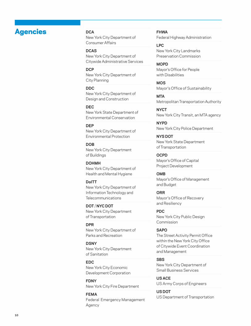
DCA New York City Department of Consumer Affairs
DCAS New York City Department of Citywide Administrative Services
DCP New York City Department of City Planning
DDC New York City Department of Design and Construction
DEC New York State Department of Environmental Conservation
DEP New York City Department of Environmental Protection
DOB New York City Department of Buildings
DOHMH New York City Department of Health and Mental Hygiene
DoITT New York City Department of Information Technology and Telecommunications
DOT / NYC DOT New York City Department of Transportation
DPR New York City Department of Parks and Recreation
DSNY New York City Department of Sanitation
EDC New York City Economic Development Corporation
FDNY New York City Fire Department
FEMA Federal Emergency Management Agency
FHWA Federal Highway Administration
LPC New York City Landmarks Preservation Commission
MOPD Mayor’s Office for People with Disabilities
MOS Mayor's Office of Sustainability
MTA Metropolitan Transportation Authority
NYCT New York City Transit, an MTA agency
NYPD New York City Police Department
NYS DOT New York State Department of Transportation
OCPD Mayor’s Office of Capital Project Development
OMB Mayor’s Office of Management and Budget
ORR Mayor's Office of Recovery and Resiliency
PDC New York City Public Design Commission
SAPO The Street Activity Permit Office within the New York City Office of Citywide Event Coordination and Management
SBS New York City Department of Small Business Services
US ACE US Army Corps of Engineers
US DOT US Department of Transportation
Agencies

49
2
Geometry 2.0 Introduction 512.0.1 General Guidelines 52
2.1 Roadways & Lanes 542.1.1 Bike Lane & Path 55 a Bike Lane 56 b Bike Path 572.1.2 Bus Lane & Busway 60 a Bus Lane 62 b Busway 632.1.3 Shared Street 642.1.4 Plaza 66 a Permanent Plaza 67 b Interim Plaza 68
2.2 Sidewalks & Raised Medians 692.2.1 Sidewalk 70 a Full Sidewalk 72 b Ribbon Sidewalk 732.2.2 Curb Extension 74 a Curb Extension: Community Facilities 76 b Curb Extension: Bus Bulb 77 c Curb Extension: Mid-Block Narrowing 782.2.3 Raised Median 792.2.4 Pedestrian Safety Island 812.2.5 Median Barrier 82
2.3 Traffic Calming 832.3.1 Lane Narrowing & Lane Removal 842.3.2 Raised Speed Reducer 85 a Raised Speed Reducer: Speed Cushion 86 2.3.3 Gateway 87 2.3.4 Raised Crosswalk 88 2.3.5 Chicane 892.3.6 Neighborhood Traffic Circle 902.3.7 Roundabout 912.3.8 Raised Intersection 93
50
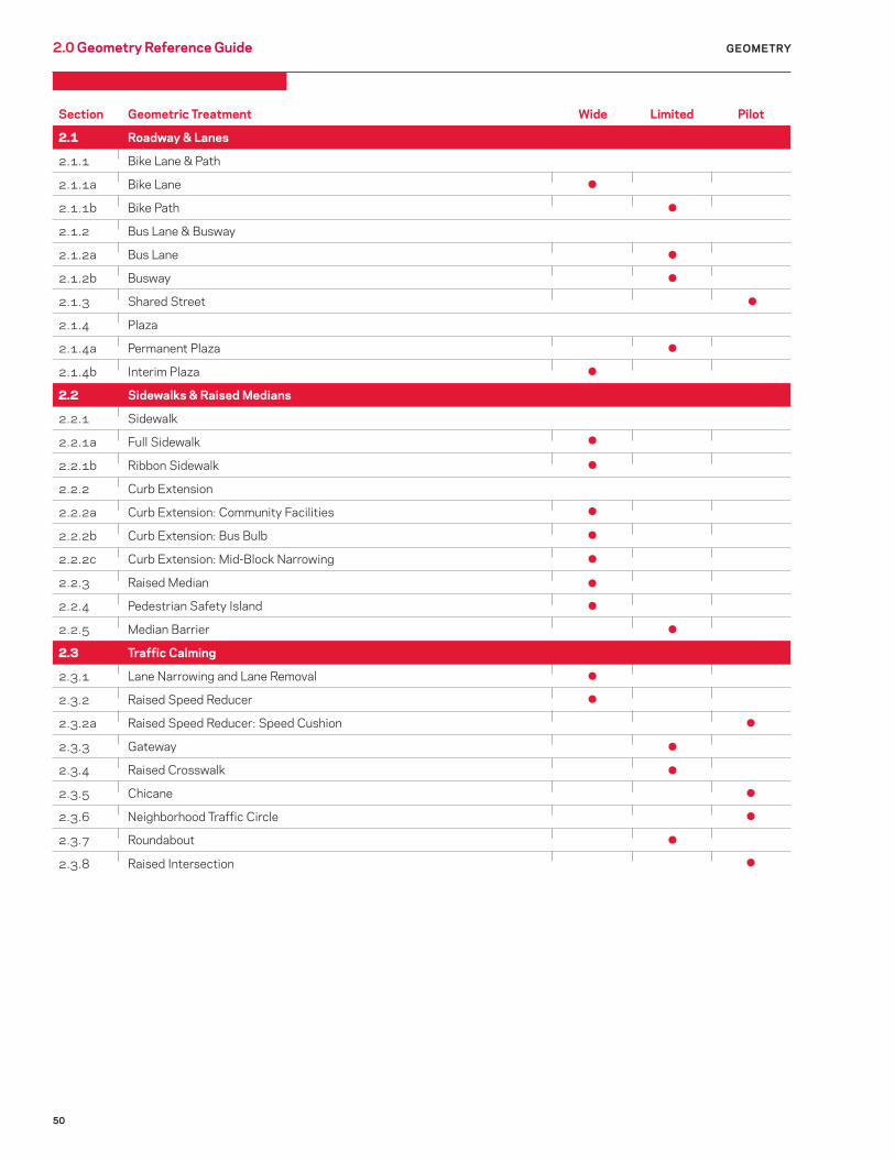
2.0 Geometry Reference Guide GEOMETRY
Section Geometric Treatment Wide Limited Pilot
2.1 Roadway & Lanes
2.1.1 Bike Lane & Path
2.1.1a Bike Lane
2.1.1b Bike Path
2.1.2 Bus Lane & Busway
2.1.2a Bus Lane
2.1.2b Busway
2.1.3 Shared Street
2.1.4 Plaza
2.1.4a Permanent Plaza
2.1.4b Interim Plaza
2.2 Sidewalks & Raised Medians
2.2.1 Sidewalk
2.2.1a Full Sidewalk
2.2.1b Ribbon Sidewalk
2.2.2 Curb Extension
2.2.2a Curb Extension: Community Facilities
2.2.2b Curb Extension: Bus Bulb
2.2.2c Curb Extension: Mid-Block Narrowing
2.2.3 Raised Median
2.2.4 Pedestrian Safety Island
2.2.5 Median Barrier
2.3 Traffic Calming
2.3.1 Lane Narrowing and Lane Removal
2.3.2 Raised Speed Reducer
2.3.2a Raised Speed Reducer: Speed Cushion
2.3.3 Gateway
2.3.4 Raised Crosswalk
2.3.5 Chicane
2.3.6 Neighborhood Traffic Circle
2.3.7 Roundabout
2.3.8 Raised Intersection
51
2.0 IntroductionGEOMETRY
About this ChapterThe geometric design of streets is integral to their use; for instance, overly wide roadways and corners with large turning radii tend to invite speeding and create an environment that is uncomfortable for pedestrians. Pedestrian ramps improve transitions for users, particularly people with disabilities. Geometry also affects streets’ economic, community, and environmental impacts.
This chapter establishes general guidelines for the geometric design of streets as well as a “toolbox” of geometric treatments that may be used to enhance safety, mobility, and sustainability.
The recommendations of this chapter supplement rather than replace existing sources of detailed engineering guidance and do not supersede any existing federal, state, or city laws, rules, and regulations. All projects remain subject to relevant statutes, such as the Zoning Resolution of the City of New York, City Environmental Quality Review (CEQR) and appropriate reviews and approvals of oversight agencies.
Guidance SourcesGuidance on the geometric design and operations of streets and roadways is contained in such sources as A Policy on Geometric Design of Highways and Streets (AASHTO, 2011), the Manual of Uniform Traffic Control Devices (FHWA, 2003), the 2010 ADA Standards for Accessible Design (USDOJ, 2010), the Urban Bikeway Design Guide (NACTO, 2012), and the Urban Street Geometric Design Handbook (ITE, 2008).
Other resources include the Guide for the Planning, Design, and Operation of Pedestrian Facilities (AASHTO, 2004), Inclusive Design Guidelines (MOPD, 2010), Designing Walkable Urban Thoroughfares: Context Sensitive Approach (ITE, 2010), the Urban Street Design Guide (NACTO, 2013), and New York City’s Active Design Guidelines (2010). Readers should also refer to DOT’s Measuring the Street: New Metrics for 21st Century Streets (2012) and the New York City Pedestrian Safety and Action Plan (2010). For additional references, see Appendix B.
Applicability and ExceptionsAll new projects that significantly impact public and private streets should follow these guidelines. DOT approval will be based on site-specific conditions and cost-effective engineering standards and judgment, with the safety and accessibility of all street users being of paramount importance.
Usage CategoriesGeometric treatments are divided into three categories: Wide, Limited, and Pilot applications.
WideGeometric treatments of this type are in wide use throughout New York City. They constitute the basic set of elements that are typically found on city streets. Designs should incorporate them wherever appropriate. These treatments generally require less intensive review than limited or pilot treatments.
LimitedGeometric treatments of this type are currently in limited use in New York City. While the designs are well-established, their application is contingent on site-specific conditions. These treatments will require more in-depth review of appropriateness and feasibility.
PilotGeometric treatments of this type are currently in, at most, limited use in New York City, but have been employed successfully in other US and international cites. Appropriate design criteria are still under development for application in New York City. Proposals for pilot usage of these treatments are encouraged and will be evaluated on a case-by-case basis.
Introduction
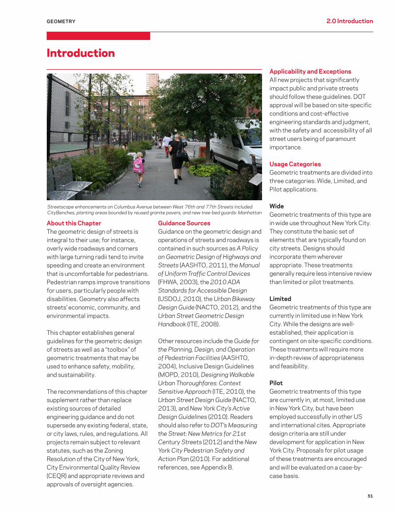
Streetscape enhancements on Columbus Avenue between West 76th and 77th Streets included CityBenches, planting areas bounded by reused granite pavers, and new tree-bed guards: Manhattan
52
Sustainable Street DesignStreet reconstruction projects are, as a rule, designed to accommodate motor vehicle traffic that is forecasted for a certain year (the “design year”) in order to meet requirements of the Clean Air Act; and in many jurisdictions in the United States the forecast invariably calls for growth in motor vehicle traffic. For federally funded projects, the design year is 20 years after the project is completed (the “build year”). In New York City, consideration should be given to recent trends in traffic and mode choice — as documented in DOT’s Sustainable Streets Index — and their implication for traffic volumes in future years (e.g., five years after the build year). In most parts of the city, motor vehicle traffic volumes are stable or shrinking, while transit is growing; this is due to New York City’s heavy investments in the last two decades in subway, bus, pedestrian, and bicycle infrastructure. These investments have spurred rapid increases in non-auto travel, suggesting that there is a positive relationship between street design and mode choice: streets that prioritize the safety and movement of pedestrians, bus riders, and cyclists equally with the movement of cars will produce more sustainable outcomes.
As the New York State DOT’s Project Development Manual states, it is understood that, even for a federally funded project, it “…may not always be practicable to…fully accommodate design year traffic, or even to fully address existing traffic congestion.” Further, “…traffic forecasts alone do not dictate project scope. Forecasts are only one of many factors (safety needs, mobility needs, environmental issues, community needs, etc.) to be addressed.” (See p. 5 – 2 Design Year Traffic Forecasts section of the Project Development Manual for more information: www.dot.ny.gov/divisions/engineering/design/dqab/dqab-repository/pdmapp5.pdf.)
Vehicle Target SpeedStreets should be designed with target speeds (see Glossary) and speed limits appropriate to their surrounding uses and desired role in the vehicular network. The citywide speed limit is 25 mph, except where otherwise noted. New York State Vehicle & Traffic Law (VTL) Section 1642(a)(26)(a) currently allows speed limits below 25 mph, and as low as 15 mph in New York City if used in conjunction with traffic-calming measures. Slower target speeds and speed limits should be considered on
General Guidelines
The following guidelines expand on the general policies and principles outlined in the Introduction, with more detailed information specific to geometric street design.
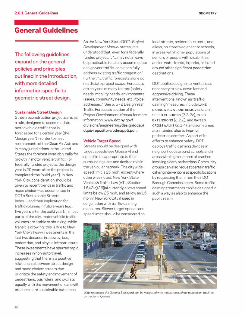
Wide roadways like Queens Boulevard can be mitigated with measures such as pedestrian facilities on medians: Queens
2.0.1 General Guidelines GEOMETRY
local streets, residential streets, and alleys; on streets adjacent to schools; in areas with higher populations of seniors or people with disabilities; and on waterfronts, in parks, or in and around other significant pedestrian destinations.
DOT applies design interventions as necessary to slow down fast and aggressive driving. These interventions, known as “traffic-calming” measures, include LANE
NARROWING & LANE REMOVAL (2.3.1),
SPEED CUSHIONS (2.3.2a), CURB
EXTENSIONS (2.2.2), and RAISED
CROSSWALKS (2.3.4), and sometimes are intended also to improve pedestrian comfort. As part of its efforts to enhance safety, DOT deploys traffic-calming devices in neighborhoods around schools and in areas with high numbers of crashes involving elderly pedestrians. Community groups can also request certain traffic-calming interventions at specific locations by requesting them from their DOT Borough Commissioners. Some traffic-calming treatments can be designed in such a way as also to enhance the public realm.

53
2.0.1 General GuidelinesGEOMETRY
Roadway Width, Corner Radii, and Crossing DistanceThe roadway — the portion of a street designed, enhanced, or ordinarily used for vehicular travel, exclusive of the sidewalk — should be designed to be the minimum possible width, with the minimum number of lanes, that safely and cost-effectively allows for the desired operations of motor vehicles, buses, and bicyclists. Narrower roadways minimize pedestrian crossing distances, encourage safe driving behavior, and reduce impermeable, heat-absorbing asphalt coverage.
Roadway reconstructions should be designed for traffic volumes expected in the actual build year. Additional consideration should be given to recent trends in traffic and mode choice — as documented in DOT’s Sustainable Streets Index — and their implication for traffic volumes in future years (e.g., five years after the build year). Excess width should be reallocated to provide walking, transit, and bicycling facilities, public open space, green cover, and/or stormwater source control measures. If financial limitations preclude final implementation of street retrofits (e.g., curbing, streetscaping, etc.), the reallocation of space should still proceed with temporary or least costly approaches such as restriping.
To reduce pedestrian crossing distances further and slow turning vehicles, all roadway corners should be designed with the smallest possible radius that still accommodates the design vehicle and emergency vehicles.
Pedestrian crossing distances should be minimized in all locations utilizing the above methods and other treatments, such as CURB
EXTENSIONS (2.2.2) (neckdowns) and RAISED MEDIANS (2.2.3). Sidewalk narrowings and roadway widenings should be avoided.
Design Vehicles and Emergency AccessThe design vehicle (see Glossary) used for geometric street designs, typically a 30-foot-long single-unit truck, should be appropriate to the predominant intended uses of the given street and should not include commercial vehicles larger than New York City’s maximum allowable length. In addition, all street designs must consider FDNY, other emergency-vehicle, and sanitation-vehicle-access needs (e.g., for street cleaning and snow clearing).
Complex IntersectionsMulti-leg or skewed angle intersections should be redesigned (to the extent possible) to simplify operations and reduce or separate conflicts. This can include the removal of intersection legs and slip lanes that are unimportant to the traffic network, creation of right-angled intersection alignments, and simplified traffic patterns. Resulting pedestrian space should be consolidated into its most usable form to create new public open
space and shorter, more direct crossings. The use of slip lanes should generally be avoided unless they produce a conflict-free crosswalk from the island that can provide an important pedestrian-safety enhancement.
Universal DesignProjects must meet or exceed all applicable federal, state, and/or local accessibility standards for facilities and public rights-of-way, including minimum clear path widths, inclusion of ADA-compliant pedestrian ramps and detectable warning strips, and provision of accessible transit facilities.
DrainageAll modifications to street geometry should consider and avoid unintended changes in the direction and disposition of stormwater runoff so as not to create ponding or flooding issues. Minimize impervious paved areas and utilize permeable paving wherever possible. Include planted areas and stormwater source controls within the roadway wherever feasible. Stormwater control within the street network may offer opportunities for resiliency benefits in areas that experience frequent flooding.
DOT upgraded the complex intersection of Melrose Avenue, Third Avenue, and East 149th Street – known as the Hub – in 2008: Bronx

54
Geometry2.0 Introduction2.1 Roadways & Lanes GEOMETRY
Roadways & Lanes

55
GEOMETRY: ROADWAYS & LANES 2.1.1 Bike Lane & Path
Benefits
Provides dedicated space for bicyclists, enhancing safety, comfort, and mobility
Cumulative with other bikeways, provides a comprehensive network of recommended routes for bicyclists, thereby encouraging bicycling
Application
On streets with high current or anticipated bicycle volumes or that offer important linkages to destinations or between routes, or to calm overly-wide roads for cycling circulation
Bike Lane & Path A dedicated on-street lane or path for bicycles (see Glossary). Bikeways are typically designed as BIKE LANES within the roadway delineated with markings (2.1.1a, also known as Class 2 bike lanes) or as BIKE PATHS physically separated from traffic for most of their length (2.1.1b, also known as Class 1 bike lanes). Another typical design is the shared lane (Class 3 bike lane) described in Table 1. The shared lane is not covered by the Manual. Bikeways in parks, or in other places with heavy pedestrian traffic can also be designated by bike stamps.
Considerations
Ensure sufficient outreach to people with vision disabilities and facilities serving this population to provide adequate notification of changes during the planning and implementation phases
Design
See Table 1 (following 2.1.1b) for a listing of typical bikeway designs and their respective spatial requirements, ideal applications, and advantages and disadvantages
Create connectivity with adjoining bikeways, bike parking, transit, and commercial or cultural destinations
LEFT: Two-way, parking-separated bike path: Prospect Park West, Brooklyn
ABOVE: Buffered bike lane: 9th Street, Brooklyn
Utilize permeable paving and/or paving with a high SRI value within BIKE LANE or BIKE PATH
Utilize recycled content in paving materials

56
Benefits
See benefits of BIKE LANES & PATHS (2.1.1)
On-roadway bike lanes that narrow or replace motor vehicle lanes can calm traffic
Considerations
Without physical separation, vehicles can block bike lanes, making enforcement of violations more critical
GEOMETRY: ROADWAYS & LANES2.1.1a Bike Lane
Bike Lane Usage: Wide
A portion of a roadway that has been designated by striping, signs, and pavement markings for the preferential or exclusive use of bicyclists. Also known as a Class 2 bike lane. Physical separation of bike lanes is desirable, but is not always possible due to physical or operational constraints designated by bike stamps.
Application
See application guidance for BIKE
LANES & PATHS
Consider using a BIKE PATH (2.1.1b) rather than, or in addition to, a BIKE
LANE where street conditions permit (e.g., street width, traffic volume, etc.)
LEFT: Bike lane: Montgomery Street, Manhattan
Design
See design guidance for BIKE LANES &
PATHS
BIKE LANES should be buffered when possible, typically with 3 feet of channelization
At intersections with complex traffic patterns — or when bike lanes are located immediately adjacent to the curb — bike lanes can be given visual emphasis through the application of green-colored pavement
BIKE LANE & PATH
ABOVE: Bike lane: 164th Street, Queens

57
Benefits
See benefits of BIKE LANES & PATHS
(2.1.1)
Offers greatest bicyclist separation from motor vehicle traffic on mid-block sections
Reduces risk of “dooring” (a motor-vehicle occupant opening her door into the path of an oncoming bicyclist)
Reduces or eliminates blocking of the bike lane by motor vehicles and the swerving of bicyclists into mixed traffic
Encourages novice and less confident cyclists to opt for cycling
Considerations
Design consideration must be given to pedestrians with vision/mobility disabilities, emergency-vehicle and paratransit access to adjacent buildings, snow-clearing and street-sweeping needs, and commercial vehicles loading and unloading
Bike Path Usage: Limited
A path intended for the use of bicycles that is physically separated from motorized vehicle traffic by an open space or barrier and either within the roadway or within an independent right-of-way. Also known as a Class 1 bike lane. Physical separation of bikeways can sometimes be preferable on wide or busy streets, on major bike routes, or along long, uninterrupted stretches. Separation can take the form of a painted buffer demarcating the bike lane behind a “floating” parking lane, a narrow curb or raised median, or a wider raised median with landscaping. An alternative form of separation is grade-separation, where the bike path is located at sidewalk grade or in between sidewalk and roadway grade.
Application
Where a BIKE LANE is appropriate and the street is an important bicycle network connection, or has high motor vehicle volumes or speeds or multiple moving lanes, or is along a park, waterfront, or other open space where cross streets and driveways are infrequent
Consider wherever a BIKE LANE is appropriate
Design
See design guidance for BIKE LANES &
PATHS (2.1.1)
Care must be given to the design of bike paths at intersections and driveways to maintain visibility of the bicyclist to motorists (and vice-versa) and to reduce the risk of turning conflicts with motor vehicles
In some circumstances (e.g., long paths along open space or waterfront), paths can be designed for shared use by bicyclists, pedestrians, skaters, wheelchair users, and other non-motorized users (“a shared-use path”) rather than as a separate bike path and SIDEWALK (2.2.1)
If designed as a shared-use path, provide adequate space appropriate to anticipated volumes of low-speed users (pedestrians) and higher-speed users (bicyclists) so as to provide safe and comfortable accommodation of both and minimize conflicts between the two
Design RAISED MEDIANS that separate bike paths according to the RAISED
MEDIAN section (2.2.3)
If a separated bike path uses raised medians, see the CURB-HEIGHT
MEDIAN section (6.2.1a) or the RAISED
MEDIAN section (6.2.1b) for information on plantings
GEOMETRY: ROADWAYS & LANES 2.1.1b Bike Path
Two-way bike path: Grand Army Plaza, Brooklyn Two-way bike path located outside the sidewalk: Columbia Street, Brooklyn
BIKE LANE & PATH

58
GEOMETRY: ROADWAYS & LANES2.1.1 Bikeway
Protected Path with Mixing ZonesGrand Street, Manhattan
8 feet14 feet
High 5–6 parking spaces/ turn bay (usually every other block)
High 4–5 parking spaces/mixing zone (usually every other block)
Commercial Avenues o Wide one-way multilane street o Excess road space o High-speed vehicular traffic o High potential for motor vehicle intrusion into standard lane
Commercial Cross-Streets o One- or two-lane street o Excess road space o Low-speed vehicular traffic for safe mixing zone
o High potential for motor vehicle intrusion into standard lane
o Full protection for cyclists o Major enhancement to pedestrian safety and comfort
o Protection for cyclists mid-block o Mixing zone to manage turning conflict o Simpler implementation than Signal Protected Path
o Signal timing unchanged
o Space needs o Parking impacts o Signal timing and loading activity increase delays
o Cyclist mobility o Complex review and implementation o Turn restrictions may be needed at complex intersections to maintain acceptable operations
o Parking impacts o Cyclist mobility o Unproven (Pilot) o Complex review and implementation o Challenging to regulate floating parking
Space Required
Parking Loss
Ideal Application
Advantages
Disadvantages
Signal-Protected Path9th Avenue, West 59th to 16th Streets, Manhattan
Class 1: Bike Path (2.1.2b)Guide to New York City On-Street Bicycle Facilities
TABLE 1

59
Buffered LaneDeKalb Avenue, Brooklyn
Standard Lane21st Street, Manhattan
Shared Lane48th Street, Queens
Signed Route
8 feet 5 feet None A wide (13-foot) travel lane is preferred
None A wide (13-foot) travel lane is preferred
Medium - Low Parking typically preserved unless space unavailable. Strict curb regulations sometimes needed
Medium -Low Parking typically preserved unless space unavailable. Strict curb regulations sometimes needed
LowParking is typically preserved
None
Residential Avenues o Wide multilane street o Excess road space o Low potential for intrusion into bicycle lane
Residential Cross-Streets o One- or two-lane street o Excess road space o Low potential for intrusion into bicycle lane
Narrow Streets o One- or two-lane street o No excess road space o Connected to other bicycle facilities
Limited Use o Interim treatment o Connected to other bicycle facilities
o Indicates a preferred bicycle route
o Preserves curbside access
o Dedicated cycling space o Buffer zone enhances comfort for cyclists
o Preserves curbside access
o Simple implementation
o Dedicated roadway space for cycling
o Preserves curbside access
o Simple implementation
o Clear, easy to follow bicycle route
o Heightens driver awareness of cyclists
o Preserves curbside access
o Simple implementation
o Indicates a preferred bicycle route
o Preserves curbside access
o Simple implementation
o Vehicular intrusion remains possible
o Width tempts motorists to intrude
o Perceived as less safe than protected paths
o Vehicular intrusion remains possible
o Cyclists have minimal separation from traffic
o Perceived as less safe than protected paths
o Does not provide dedicated roadway space for cycling
o Cyclists not separated from traffic
o Does not provide dedicated roadway space for cycling
o Cyclists not separated from traffic
o Sign placement critical, can be challenging
Class 2: Bike Lane (2.1.2a) Class 3: Bike Route (Not Included in Manual)
GEOMETRY: ROADWAYS & LANES 2.1.1 Bikeway

60
Benefits
Improves bus speeds and reliability by separating buses from potential congestion in mixed traffic and by reducing or eliminating their need to merge in and out of traffic at bus stops
SBS buses operate up to 20% more efficiently than the same bus models operating on other routes, thereby reducing emissions
Provides means for emergency vehicles to bypass traffic
Considerations
If curbside, may result in restriction of curbside parking/loading
Application
Streets with SBS or high bus volumes and moderate to high traffic congestion or excessive road space
Consider on all streets with high bus volumes or existing or planned SBS and adequate space, regardless of congestion
Avoid on streets where the roadway geometry prevents the safe operation of a BUS LANE or BUSWAY in conjunction with other necessary uses of the roadway
Bus Lane & Busway
2.1.2 Bus Lane & Busway
A dedicated on-street facility for buses. BUS LANES are delineated within the roadway with markings (2.1.2a) while BUSWAYS are physically separated from traffic for most of their length (2.1.2b). Both facility types can either be designed to run along the median of the street or along the outside (curbside or offset from a parking lane) of the street. Select Bus Service (SBS) is a high-quality bus service operated by MTA New York City Transit that uses several techniques to improve the speed and reliability of bus service, including BUS
LANES.
GEOMETRY: ROADWAYS & LANES
Red, curb-aligned, on-street busway with “soft separation” from traffic: First Avenue, Manhattan

6161
Design
BUS LANES AND BUSWAYS can be located immediately adjacent to the curb (curb bus lane or busway), adjacent to the righthand parking lane (offset bus lane), or in the middle of a road with boarding island stations (median bus lane or busway)
ALL BUS LANE AND BUSWAY types can be one or two lanes per direction based on bus volume, operating characteristics, and road width; one lane per direction is a more common treatment
Use an offset bus lane where possible, particularly when parking needs to be maintained; stops can be made at the curb or at BUS BULBS (2.2.2b)
Use a curb-aligned bus lane or busway when right-of-way may be constrained and where parking impacts can be managed
For curb-aligned designs, curbside deliveries can be accommodated with loading windows, lay-bys, and/or reserved commercial loading around the corner
A median BUS LANE or BUSWAY should be considered on two-way streets when sufficient right-of-way is available to accommodate the bus facility and the associated boarding islands, and the operation of the busway (including pedestrian movements) can be safely managed
For median bus lane or busway designs, boarding platforms must be included for bus passengers at bus stops; these islands can also function as PEDESTRIAN SAFETY ISLANDS (2.2.4)
For median bus lane or busway designs, left turns across the bus facility should either be prohibited or provided a protected signal phase
All BUS LANE AND BUSWAY designs can accommodate one or two directions of bus traffic. Special care must be paid to the signalization and design of intersections so as to not introduce turning conflicts
Consider queue-jump lanes for buses where buses need to merge with mixed traffic, where the roadway width reduces (such as at the end of a bus lane, a roadway choke point, or a bridge or tunnel approach), and at turn priority locations
For improved roadway longevity, a concrete roadway should be considered for BUS LANES AND
BUSWAYS when conditions permit
Utilize paving with a high SRI value within bus lane or busway unless red-colored pavement is to be used per 2.1.2a
Utilize recycled content in paving materials
GEOMETRY: ROADWAYS & LANES 2.1.2 Bus Lane & Busway

62
GEOMETRY: ROADWAYS & LANES2.1.2a Bus Lane & Busway: Bus Lane
Bus Lane Usage: Limited
Benefits
See benefits of BUS LANES &
BUSWAYS (2.1.2)
Considerations
See considerations for BUS LANES &
BUSWAYS (2.1.2)
Application
See application guidance for BUS
LANES & BUSWAYS (2.1.2)
Design
See design guidance for BUS LANES &
BUSWAYS
Red-colored pavement can be considered for bus lanes that operate six or more hours per day
At intersections, the allowance or prohibition of turns from the bus lane should be clear, such as breaking the solid white line where cars can enter to make right turns
A portion of a roadway which has been designated by striping, signing, and pavement markings for the preferential or exclusive use of buses. Physical separation of bus lanes is often inadvisable due to physical or operational constraints. Painted lanes, overhead signs, and soft barriers can minimize intrusion of other vehicles. Where land use and street width permit, full or partial physical separation can help enforce the lanes (see 2.1.2b).
Red, curb-aligned bus lane: East Fordham Road, Bronx
Curb-aligned double bus lane: Madison Avenue, Manhattan
BUS LANE & BUSWAY

63
GEOMETRY: ROADWAYS & LANES 2.1.2b Bus Lane & Busway: Busway
Benefits
See benefits of BUS LANE & BUSWAY (2.1.2)
Reduces or eliminates blocking of BUS
LANE (2.1.2a)
Considerations
Design consideration must be given to emergency vehicle access, deliveries and pick-up/drop-off to adjacent buildings, and to snow-clearing and street-sweeping needs
Attention should be given to accommodation of and navigation by people with vision disabilities
Busway Usage: Limited
Application
See application guidance for BUS
LANES & BUSWAYS
Consider where a BUS LANE is appropriate and the street is a high-volume bus route and has adequate right-of-way to accommodate a busway
Consider wherever a BUS LANE is appropriate
Design
See design guidance for BUS LANES &
BUSWAYS
Busways should be designed to allow emergency vehicles to bypass traffic
On routes with multiple tiers of bus service, passing needs (e.g., express buses) should be accommodated
A physically separated lane reserved for bus traffic. Busways are similar to BUS LANES (2.1.2a) in most respects, however full or partial physical separation (typically through a narrow curb or wider RAISED MEDIAN (2.2.3) further improves bus speeds by minimizing blocking of the bus lane by other vehicles.
ABOVE: Curb-aligned busway: Paris, France (Note: for illustrative purposes only)
If a median busway design is not separated with a wide median, then the median must widen to provide boarding platforms for bus passengers at bus stops, which must meet ADA standards
Turns across busways need to be controlled for safety; bus-only signals may be needed
Crosswalks , detectable warning strips and traffic control devices should be used to signal transitions between pedestrian space and busways for people with vision disabilities
RAISED MEDIANS used to separate busway should be designed according to the RAISED MEDIAN section
Utilize paving with a high SRI value within busway, for example concrete
For median-separated busway, see the CURB-HEIGHT MEDIAN section (6.2.1a) for information on plantings
BUS LANE & BUSWAY
LEFT: A short section of separated busway through a busy intersection: Willis Avenue, Bronx

64
Benefits
Allows freer pedestrian movement within walking-oriented areas and to and from surrounding land uses and destinations
Reduces sidewalk crowding on narrow streets
Maintains bicycle, local vehicle, and delivery access while creating an exceptionally pedestrian-oriented street that accommodates recreational and social activities
Allows active land uses to spread into the surrounding street network, fostering a vibrant public realm
Considerations
Attention should be given to accommodation of and navigation by people with vision, hearing, and ambulatory disabilities
May impact street drainage or require catch basin relocation
May require loss of on-street parking
Any community facilities integrated into the design, such as street furniture or public art, will typically necessitate the presence of a maintenance partner and a permit or revocable consent from the city
Coordinate streetscape/utility work to minimize street cuts
Comfortable, attractive environment encourages “staying” activities such as relaxing, shopping, eating, and socializing
Integrated design can incorporate art, street furniture, landscaping, and other innovative and attractive design elements
Encourages partnerships with the community in beautification, maintenance, and programming of street space
GEOMETRY: ROADWAYS & LANES2.1.3 Shared Street
Shared Street Usage: Pilot
Often referred to as a “pedestrian-priority street,” a shared street is a low-speed, typically curbless roadway designed as a single surface shared among pedestrians, bicyclists, and low-speed motor vehicles.
Typically employed on low-vehicle-volume and/or high-pedestrian-volume streets, vehicles are slowed to very low speeds through a reduced speed limit, traffic calming, signage, and use of distinctive materials, furnishings, and other visual cues in the roadway that encourage drivers to travel with increased caution. Street users generally negotiate right-of-way cooperatively rather than relying on traffic controls, allowing pedestrians to dominate the street. The entire street thus effectively functions as a public space. Different forms of shared streets can be used in different contexts.
ABOVE: Shared street: Mainz, Germany (Note: for illustrative purposes only)
LEFT: Shared street in a commercial area: Brighton, UK (Credit: Gehl Architects) (Note: for illustrative purposes only)
6565
Application
Consider on narrower streets (at most two moving lanes) or outer roadways of boulevard-type streets, with little or no through-traffic, and which are not major vehicular or bicyclist through-routes or designated truck routes
Consider on streets adjacent to major pedestrian destinations, where vehicle volumes are low and pedestrian desire lines are diffuse (i.e., pedestrians would like to cross the street in many places)
Consider on local residential streets whose design priority is to allow safe use of street space for recreational activities and green space, in partnership with residents or neighborhood groups
Consider on narrow, alley-type streets
Depending on the specific land uses, width, vehicle and pedestrian volumes, and other access and operational characteristics of the street, a shared street may not be appropriate, in which case consideration should be given to a standard roadway with alternative design options such as traditional traffic calming and/or a mid-block crossing
Consider as an alternative a fully pedestrianized street when pedestrian volumes are high, vehicle volumes are low, and vehicle access is not required during daytime hours
GEOMETRY: ROADWAYS & LANES 2.1.3 Shared Street
Design
Curbs should not be used, but pedestrian paths of travel alongside vehicle zones with guideways using tactile cues and maximum visual contrast should be included for people with vision disabilities
In the absence of curbs, special attention should be given to providing adequate drainage
Vehicle-free, accessible routes must be provided for the visually impaired
Design should utilize whatever horizontal, vertical, and material treatments are necessary to encourage vehicle speeds that are low (15 mph or lower) throughout, whether or not pedestrians are present
Use GATEWAY (2.3.3) or similar treatments and proper signage at entries to discourage through-traffic, indicate the change in street environment, and slow entering vehicles
Institute a reduced speed limit (New York State VTL Section 1642(a)(26) (a) currently allows as low as 15mph) along with the physical traffic-calming of the shared street
Attractive street materials, furnishings, and other objects within the street can be used to alert drivers and emphasize the pedestrian orientation of the space, subject to permits, maintenance agreements, or revocable consents as required
Include planted areas and stormwater source controls within the roadway wherever possible
Staggered sections of parking or loading zones can be used as a design option to constrict wider streets
To maintain the streetscape elements required for creating a low-speed environment and fostering a vibrant public space, careful attention must be paid to proper programming and management of the space, with the participation of an active maintenance partner where appropriate
Minimize impervious paved areas and utilize permeable paving wherever possible
Maximize trees and other green cover. See TREE BEDS (6.1) and ROADWAY
PLANTINGS (6.2)
Utilize stormwater source controls wherever feasible. See STORMWATER
MANAGEMENT PRACTICES (6.6)
Increase SRI value of paved surfaces to reduce urban heat island impact
Utilize recycled content in paving materials
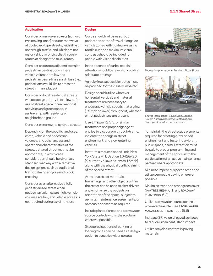
Pedestrian-priority zone: Fordham Plaza, Bronx
Shared intersection: Seven Dials, London (Credit: Aaron Naparstek/streetsblog.org) (Note: for illustrative purposes only)

66
Benefits
Promotes social interaction and builds neighborhood identity
Encourages pedestrian activity and associated health benefits
Catalyzes local economic development
Serves as a venue for a diverse range of community, cultural, and/or commercial events
Enhances safety by narrowing wide roadways and/or normalizing intersections
Considerations
The road segment’s relevance to the traffic network
Open-space needs
Surrounding land uses and site appropriateness
Anyone can apply to the Street Activity Permit Office (SAPO) to stage events on DOT plazas. To learn more about the event permitting process, contact SAPO by phone at (212) 788-7567 or visit www.nyc.gov/cecm
Advertising is not permitted in plazas
Generally requires a maintenance agreement
Application
Under-utilized, DOT-owned road segments and other city property
Locations with high crash rates
Neighborhoods that support repurposing streets for plazas
Design
Plaza designs should support year-round events and programs
See design guidance for PERMANENT
PLAZA (2.1.4a) and INTERIM PLAZA (2.1.4b)
Provide clear paths and tactile cues to accommodate people with disabilities
Furniture should accommodate people with disabilities; for example, providing space for knee clearance for people using mobility devices
GEOMETRY: ROADWAYS & LANES2.1.4 Plaza
Plaza
An area located fully within the roadway that is designated by DOT for use by pedestrians. The space may contain benches, tables, or other facilities. DOT builds both interim and permanent plazas. Many plazas are built through DOT’s Plaza Program, which aims to enhance the public realm. See Chapter 1: PROCESS for more information on how DOT projects are planned, designed, and implemented.
LEFT: Willoughby Plaza (permanent), Brooklyn
ABOVE: Fowler Square Plaza (interim), Brooklyn

67
Benefits
See benefits of PLAZA (2.1.4)
Considerations
See considerations for PLAZA (2.1.4)
Application
See application guidance for PLAZA (2.1.4)
Neighborhoods with active not-for-profit organizations that can serve as Partners to maintain and manage plazas
Areas with appropriate adjacent land uses, sufficient population density, proximity to transit, historic sites, significant view corridors
Design
Each permanent plaza is designed to reflect the character and context of its neighborhood. DOT and the Partner conduct a public process to develop an appropriate design that is responsive to the needs of the community
A consultant design team bases its plans on feedback from the public process
Sites smaller than 2,000 square feet are not encouraged
Plazas may include movable and/or formal and informal fixed seating; trees and plants (see TREE BEDS [6.1] and PLAZA PLANTINGS [6.4]); lighting; paving; information and wayfinding signage; subconcessions; public art (temporary and permanent); bicycle parking; and drinking-water fountains
Incorporate public art where feasible
All permanent public art must be coordinated through the Department of Cultural Affairs (DCA) Percent for Art Program and requires approval by the Public Design Commission (PDC). Permanent art may be completely integrated and functional (e.g., benches, tables, etc.), or it may be stand-alone art (e.g., a sculpture)
Temporary art can be installed as a one-time project or cycled through on a temporary basis at a designated space in the plaza. Temporary art must be coordinated through DOT’s Urban Art Program. For guidelines and to apply to the Urban Art Program, visit www.nyc.gov/urbanart
Minimize impervious paved areas and utilize permeable paving wherever possible
Incorporate trees and other green cover. See TREE BEDS (6.1) and PLAZA
PLANTINGS (6.4)
Utilize stormwater source controls wherever feasible
Increase SRI (solar reflective index) value of paved surfaces to reduce urban heat island impact
Utilize recycled content in paving materials
GEOMETRY: ROADWAYS & LANES 2.1.4a Permanent Plaza
A plaza built with Capital funds to be maintained and managed by a local not-for-profit organization (Partner) or another entity, such as the Department of Parks & Recreation (DPR). Such a project completely reconstructs the street segment, in whole or in part.
Completed in spring 2013, Willoughby Plaza features new trees and a flexible, open space that lends itself well to a wide range of events and programming, including the art displays shown here: Brooklyn
Permanent Plaza Usage: Limited
PLAZA
68
Benefits
See benefits of PLAZA (2.1.4)
Catalyzes community support for the space
DOT can study the interim plaza and incorporate its observations and feedback into the eventual capital design of the space
Tests maintenance partner’s capacity to maintain and program the plaza
Epoxy gravel or paint creates a more reflective surface, making the space feel safer at night
Cheaper and faster to design and install than a PERMANENT PLAZA
Considerations
See considerations for PLAZA (2.1.4)
Maintenance partner replaces elements over time as needed
Attention should be given to accommodation of and navigation by people with vision disabilities
Application
See application guidance for PLAZA (2.1.4)
Typically the phase prior to a PERMANENT PLAZA (2.1.4a), delivering community benefits quickly, and generating feedback for permanent design
As requested by a community and/or where a safety project provides a public-space opportunity
Design
See design guidance for PLAZA (2.1.4)
Geometry is engineered by DOT and is typically delineated with roadway markings and flexible reflective bollards
Detectable warning strips are required at pedestrian access routes or crossings where the transition from pedestrian space to roadway is flush, and should include high color contrast from the plaza surface
In the absence of a curb, granite blocks are to be placed next to crosswalks when feasible to provide directional guidance for pedestrians with vision disabilities
DOT places edge objects, such as planters, granite blocks and flexible delineators in and around the space to create a consistent boundary and sense of enclosure, and to buffer it from motor vehicle traffic. DOT also applies epoxy gravel or paint to distinguish it visually from the adjacent roadway
DOT and/or Partners provide publicly accessible furniture, such as moveable chairs and tables
Incorporate temporary public art where feasible. See guidance for temporary art in PERMANENT PLAZA (2.1.4a)
GEOMETRY: ROADWAYS & LANES2.1.4b Interim Plaza
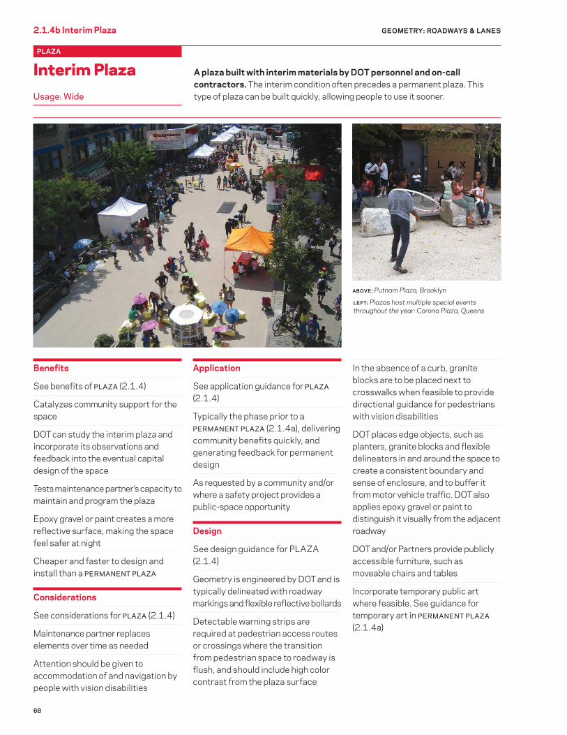
A plaza built with interim materials by DOT personnel and on-call contractors. The interim condition often precedes a permanent plaza. This type of plaza can be built quickly, allowing people to use it sooner.
ABOVE: Putnam Plaza, Brooklyn
Interim Plaza Usage: Wide
PLAZA
LEFT: Plazas host multiple special events throughout the year: Corona Plaza, Queens

69
Geometry Geometry 2.0 Introduction2.0 Introduction Geometry2.0 Introduction 2.2 Sidewalks & Raised MediansGEOMETRY
Sidewalks & Raised Medians

70
Benefits
Provides infrastructure for the most widely used mode of travel in New York City — walking
Creates linkages to transit, connects neighborhood destinations, and allows trip chaining
Support mobility for the majority of New Yorkers
Facilitates straight and unobstructed pedestrian movement, free of vehicle conflicts except at intersections and driveways
With adequate width, can provide space for “staying” activities such as relaxing, shopping, eating, and socializing
Considerations
Coordinate streetscape/utility work to minimize street cuts
Application
On both sides of all streets that are 22 feet wide or wider. Exceptions include SHARED STREETS (2.1.4), pedestrian-only, and streets in certain historic districts per LPC
Ribbon sidewalks are appropriate in R1-R6 zoning districts; full sidewalks are used elsewhere
Design
Sidewalks should always be provided on both sides of the street
See SIDEWALKS (3.1) in the Materials chapter for information on options for sidewalk materials
A park’s internal path located near a roadway does not substitute for a sidewalk
If the sidewalk is more than 25 feet wide, there should be a clear path adjacent to the building line and an 8-foot clear path adjacent to the curbside furnishing zone
Sidewalks (and planting strip, if applicable) should be as wide as possible appropriate to foot traffic and available street width
GEOMETRY: SIDEWALKS & RAISED MEDIANS2.2.1 Sidewalk
Sidewalk
That portion of a street, whether paved or unpaved, between the curb lines or the lateral lines of a roadway and the adjacent property lines intended for the use of pedestrians. Where it is not clear which section is intended for the use of pedestrians, the sidewalk will be deemed to be that portion of the street between the building line and the curb. In denser areas a FULL SIDEWALK (2.2.1a) reaching all the way to the curb is used, while in less built-up areas a RIBBON SIDEWALK (2.2.1b), with a vegetated or grass planting strip between the sidewalk and the roadway, can often be used.
Sidewalk with standard paving treatment: 11th Avenue, Manhattan

71
Sidewalks must conform to ADA requirements for minimum clear path width and provision of spaces where wheelchair users can pass one another or turn around
Provide an unobstructed clear path of 8 feet or one half the sidewalk width (whichever is greater) in commercial, high-density residential, and transit-adjacent areas
Sidewalks in low-rise residential areas should be at least 5 feet wide
Wherever possible, sidewalk cross-slope should not be greater than 2%
Sidewalks must meet load-bearing, friction, and other requirements per relevant standard specifications and regulations
ADA-compliant pedestrian ramps must be provided at all pedestrian crossings; separate ramps should be used aligned with each crosswalk and be centered on a continuation of the sidewalk
Color of detectable warning strip should contrast with surrounding pavement: dark gray in areas of light pavement and white in areas of dark pavement. See DOT Standard Details of Construction drawing H-1011
The area within 18 inches of the curb should be kept free of all obstructions
New York City Mayor’s Executive Order No.22 of 1995 (the “Clear Corner Policy”) states that to the maximum extent possible, structures and objects should not be placed in the corner quadrant
For recommended clearances between obstructions, see Revocable Consent Rules (Rules of the City of New York, Title 34, Chapter 7, Section 7-06(c)(5)), DOT Highway Rules (Rules of the City of New York, Title 34, Chapter 2, Section 2-10), DCA’s rules regarding newsstands (Rules of the City of New York, Title 6, Chapter 2, Subchapter G), and Proposed Accessibility Guidelines for Pedestrian Facilities in the Public Right of Way (US Access Board, 2011)
Include planted areas and stormwater source controls within sidewalks wherever possible when a maintenance partner is identified
If work includes tree planting, consider the location of utility infrastructure, including DEP sewers and water mains
Minimize impervious paved areas and utilize permeable paving wherever possible
Maximize trees and other green cover wherever clearance allows. See TREE
BEDS (6.1) and SIDEWALK PLANTINGS (6.3)
Utilize stormwater source controls wherever feasible
Increase SRI value of sidewalk materials to reduce urban heat island impact
Utilize recycled content in paving materials
GEOMETRY: SIDEWALKS & RAISED MEDIANS 2.2.1 Sidewalk
72
GEOMETRY: SIDEWALKS & RAISED MEDIANS2.2.1a Sidewalk: Full Sidewalk
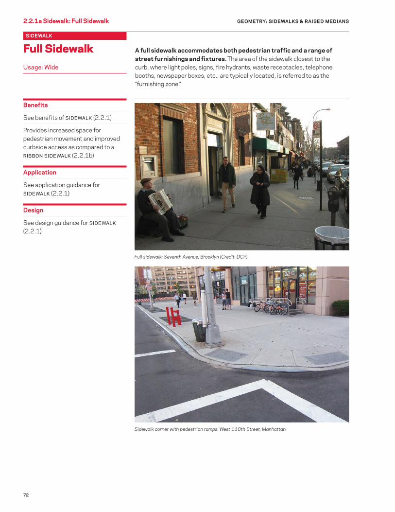
A full sidewalk accommodates both pedestrian traffic and a range of street furnishings and fixtures. The area of the sidewalk closest to the curb, where light poles, signs, fire hydrants, waste receptacles, telephone booths, newspaper boxes, etc., are typically located, is referred to as the “furnishing zone.”
Benefits
See benefits of SIDEWALK (2.2.1)
Provides increased space for pedestrian movement and improved curbside access as compared to a RIBBON SIDEWALK (2.2.1b)
Application
See application guidance for SIDEWALK (2.2.1)
Design
See design guidance for SIDEWALK
(2.2.1)
Sidewalk corner with pedestrian ramps: West 110th Street, Manhattan
Full sidewalk: Seventh Avenue, Brooklyn (Credit: DCP)
Full Sidewalk Usage: Wide
SIDEWALK

73
Benefits
See benefits of SIDEWALK (2.2.1)
Provides greater space for tree roots than a FULL SIDEWALK (2.2.1a) with INDIVIDUAL TREE BEDS (6.1.1a), improving long-term tree health
Provides a modest improvement in stormwater detention from the sidewalk and/or roadway as compared to a FULL SIDEWALK
Provides a more attractive streetscape in areas of low- to moderate-density residential land use
Application
Areas within zoning districts R1 through R6
Consider wherever pedestrian volumes can be accommodated and curbside activity is low
Design
See geometric design guidance for SIDEWALK (2.2.1) and materials guidance for SIDEWALKS (3.1)
Ribbon sidewalks should be at least 5 feet wide or as required to match the existing ribbon width in the immediate neighborhood; they should be wider along arterials and collector roads
Planting strips adjacent to ribbon sidewalks must be planted with groundcover vegetation for erosion control if a STORMWATER MANAGEMENT
PRACTICE (6.6) is not used; herbaceous plant material, preferably native or adapted species, should be used rather than grass wherever possible, as turf absorbs water from tree roots, has little benefit to habitat, and requires the use of pesticides, herbicides, fungicides, and lawnmowers that can potentially damage tree roots
Where there are fire hydrants in the planting strip adjacent to a ribbon sidewalk, a 5-foot-by-5-foot slab of 6-inch-thick concrete on 6-inch, crushed-stone base extending from the curb to the sidewalk is required
GEOMETRY: SIDEWALKS & RAISED MEDIANS 2.2.1b Sidewalk: Ribbon Sidewalk
A sidewalk that is separated from the roadway by a continuous, unpaved planting strip. Most existing ribbon sidewalks in the city have a lawn planting strip, more sustainable landscaping options should be utilized whenever possible. Alternatively, planting strips can be designed as pilot STORMWATER
MANAGEMENT PRACTICES (6.6.1) to help collect stormwater runoff.
Ribbon sidewalk with lawn planting strip: Ocean Parkway at Avenue C, Brooklyn
Ribbon Sidewalk Usage: Wide
SIDEWALK
Similar considerations apply to other elements, such as lampposts and signal posts
Where feasible, utilize STORMWATER
MANAGEMENT PRACTICE (6.6) within planting strip rather than groundcover vegetation alone to better manage stormwater

74
Benefits
Calms traffic by physically and visually narrowing the roadway
At a corner, slows turning vehicles and emphasizes the right-of-way of crossing pedestrians
Shortens crossing distance, reducing pedestrian exposure and minimum required signal time for crossing
Improves the ability of crossing pedestrians and drivers to see each other
Makes the crosswalk more apparent to drivers, encouraging them to stop in advance of the crosswalk, and reduces illegal parking within crosswalk
Reinforces lane discipline through intersection, preventing vehicle passing maneuvers in parking lane
Provides additional pedestrian space and reduces crowding, particularly for queuing at crossings and bus stops or when located at a subway entrance or other protrusion
Creates space that may be used to locate street furniture, bike parking, bus stop, public seating, street vendors, etc., potentially reducing sidewalk clutter
Keeps fire hydrant zone clear when located in front of a hydrant
Defines the ends of angle parking
Can discourage truck turns onto streets with No Truck regulations (See Rules of the City of New York, Title 34, Chapter 4, Section 4-13)
Considerations
May impact street drainage or require catch basin relocation
May impact underground utilities
May require loss of curbside parking
May complicate delivery access and garbage removal
May impact snow plows and street sweepers
GEOMETRY: SIDEWALKS & RAISED MEDIANS2.2.2 Curb Extension
Curb Extension
An expansion of the curb line into the lane of the roadway adjacent to the curb (typically a parking lane) for a portion of a block either at a corner or mid-block. Also known as neckdowns, curb extensions can enhance pedestrian safety by reducing crossing distances, can relieve sidewalk crowding, and can provide space for functional elements such as seating, plantings, and furniture. In addition, two curb extensions can be located on either side of a street to create a MID-BLOCK NARROWING (2.2.2 c) or at an intersection to create a GATEWAY (2.3.3).
RIGHT: Curb extension: Fifth Avenue, Brooklyn
ABOVE: Curb extension: Seventh Avenue, Manhattan
W
Corner Radius = 4'
5' (TYP)
Width of the parking lane minus 2 feet

75
Application
Only applicable within a curbside parking lane
Corners with marked pedestrian crosswalks in retail districts, directly adjacent to schools, at intersections with demonstrated pedestrian safety issues, on wide streets, or in areas of high foot traffic
At school crosswalks
At mid-block crossings (see MID-
BLOCK NARROWING 2.2.2c)
Intersections where a two-way road transitions to oncoming one-way operation so as to block wrong-way traffic from proceeding straight onto the one-way portion (a “blockbuster”)
Next to subway entrances or other sidewalk pinch points so as to increase pedestrian walking or queuing space
Near fire hydrants, to keep clear of parked vehicles
Consider at all corners and pedestrian crossings
Consider elongated curb extensions for some or most of a block (i.e., a widened sidewalk with lay-by areas) in areas where a full sidewalk widening would be desirable but some loading, drop-off, or parking access must be maintained
Cannot be used where curbside travel (including bus, bicycle, or general traffic) lane exists, such as those created through peak-period parking restrictions
Feasibility of curb extensions is evaluated based on engineer review of design-vehicle turning movements
Design
Curb extension width is typically two feet less than the width of the parking lane. Minimum curb extension length is typically equal to the full width of the crosswalk, however it can be longer when appropriate or necessary
A fire truck turning zone with a 50-foot outside radius should be maintained clear of physical obstructions (signs, planters, non-flexible bollards, trees)
When a curb extension conflicts with design vehicle turning movements, the curb extension should be reduced in size rather than eliminated wherever possible
At crossings that may have low pedestrian visibility, curb extension should be long enough to “daylight” the crossing, i.e., provide open sight-lines to the pedestrian crossing for approaching motorists; the additional curb extension space can be used to provide plantings (see CURB
EXTENSION [6.3.3]) or community facilities such as bicycle parking as long as visibility is not hindered
The design and placement of street furniture, trees, and plantings on a curb extension must not impede pedestrian flow, obstruct clear path, or interfere with “daylighting” the intersection, emergency operations, or sight lines
Pedestrian ramps should be aligned such that they serve as a continuation of the sidewalk, rather than within the radius of the curb extension, to accommodate direct pedestrian path
Curb extension must be designed so as to maintain drainage of stormwater from the gutter and not cause ponding; depending on site-specific grading conditions, this might include properly locating catch basins or utilizing design treatments that channel water through, around, or in
GEOMETRY: SIDEWALKS & RAISED MEDIANS 2.2.2 Curb Extension
between curb extension and the curbline
Where space permits, more functional curb extension designs, such as those with PLANTINGS (6.3), or COMMUNITY
FACILITIES (2.2.2a), such as seating or bicycle parking, should be used whenever possible
Vertical elements should be used to alert drivers and snow plow operators to the presence of the curb extension
To reduce the cost and implementation time of curb extension, trench drains can be considered instead of catch-basin relocation if a maintenance partner exists to clean the trench drain
When curb extension is used at a fire hydrant, the length of the curb extension should be equal to or greater than the No Parking zone (typically 15 feet in either direction) and the hydrant should be moved onto the curb extension
Paving on curb extension should match that of the surrounding sidewalks
Locate trees and/or plantings within curb extension where appropriate. See TREE BEDS (6.1) and CURB
EXTENSION (6.3.3)
Maximize permeable surface of curb extension
Where feasible, design planted areas within curb extension so as to capture stormwater according to current standards. See STORMWATER
MANAGEMENT PRACTICES (6.6)
Curb extensions shorten crossing distances. This is especially important for vulnerable users: Fifth Avenue, Brooklyn

76
Benefits
Provides safety and traffic calming benefits as described in CURB
EXTENSION (2.2.2)
Provides space for functional sidewalk elements outside of the sidewalk clear path, freeing sidewalk space for movement
Improves the public realm and creates useful public space, particularly in areas where public open space is in short supply
Allows limited street space to serve multiple functions, thereby increasing the performance of street infrastructure
May encourage mode shift to walking by creating a more comfortable and enjoyable walking environment
Considerations
Permits, revocable consents, and/or maintenance agreements may be required for certain elements
Bike racks must be standard DOT design unless a permit is obtained from DOT
GEOMETRY: SIDEWALKS & RAISED MEDIANS2.2.2a Curb Extension: Community Facilities
A CURB EX TENSION that provides space for community facilities such as bicycle parking, seating, and other street furniture. In areas with inadequate sidewalk width to accommodate needed functional sidewalk elements for the community, the extra space provided by a curb extension can be used for bike parking, seating, public art, gardens, plantings, or trees, alone or in combination. Similarly, all paved curb extensions can also provide space for consolidating basic sidewalk furnishings such as trash cans, newspaper racks, newsstands, and light or signal poles, where foot traffic permits.
RIGHT: Curb extension with trees and seating: 46th Street, Queens
Application
See application guidance for CURB
EXTENSION (2.2.2)
Areas without sidewalk crowding where demand exists for the community facilities and a committed partner is willing to maintain any elements that require maintenance, such as seating; a maintenance partner is not needed for a DOT bike rack
Design
See design guidance for CURB
EXTENSION (2.2.2)
Curb Extension: Community Facilities Usage: Wide
CURB EXTENSION
ABOVE: Curb extension with bike parking: North 7th Street, Brooklyn

77
GEOMETRY: SIDEWALKS & RAISED MEDIANS 2.2.2b Curb Extension: Bus Bulb
A CURB EX TENSION at a bus stop that avoids the need for buses to pull in and out of the moving lane to pick up and discharge passengers. Bus bulbs may also be designed to better support bus passengers through the inclusion of higher curbs, bus stop shelters, seating, pre-boarding payment equipment, and other bus-supportive facilities.
Benefits
Provides safety and traffic calming benefits as described in CURB
EXTENSION (2.2.2)
Speeds bus movement on streets with traffic congestion by eliminating the need for buses to maneuver in and out of the moving lane
Speeds bus movement by reducing the likelihood of bus stops being blocked by stopped vehicles
Discourages non-bus encroachment into bus-only lanes
Can allow faster bus passenger boarding
Can provide comfort and convenience to bus riders through dedicated waiting space and inclusion of bus-related amenities
When utilized at a bus stop under an elevated train line, where the bus does not pull over to the sidewalk, provides a safer space for passengers to wait, as many currently stand in the roadway
Allows additional on-street parking as compared to a standard bus stop
Application
See application guidance for CURB
EXTENSION (2.2.2)
At bus stops along bus routes where it has been determined by DOT and MTA NYCT that bus bulbs would enhance bus service
Design
For detailed design guidance, see Select Bus Service Station Design Guidelines (DOT & MTA NYCT, 2009)
See additional design guidance for CURB EXTENSION (2.2.2)
Bus bulbs should be long enough to encompass the front and rear doors of the buses that will be using it, and should extend the length of the bus stop whenever possible
Design BUS BULBS with care to accommodate accessibility needs, taking into account the full range of buses that might be using the stop
Bus bulb: First Avenue, Manhattan
A bus bulb under an “El” (elevated subway): Jerome Avenue, Bronx
Bus Bulb Usage: Wide
CURB EXTENSION
6–10.5" H6–8'
40–150'
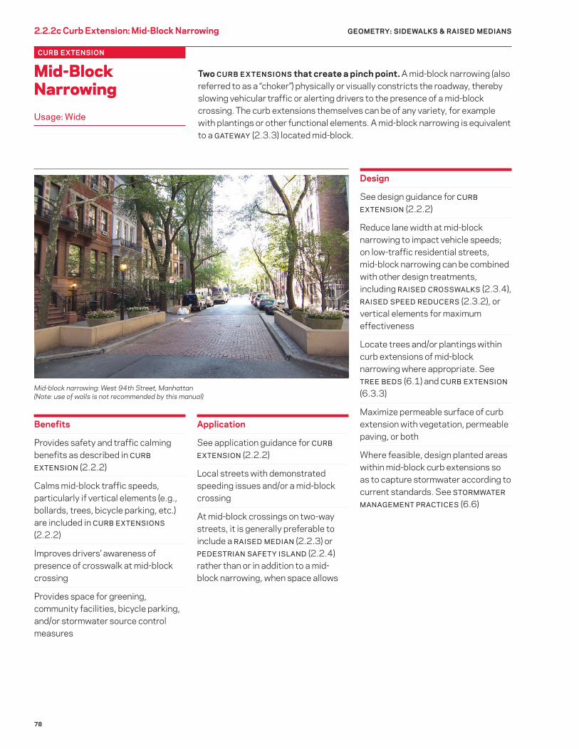
78
Benefits
Provides safety and traffic calming benefits as described in CURB
EXTENSION (2.2.2)
Calms mid-block traffic speeds, particularly if vertical elements (e.g., bollards, trees, bicycle parking, etc.) are included in CURB EXTENSIONS (2.2.2)
Improves drivers’ awareness of presence of crosswalk at mid-block crossing
Provides space for greening, community facilities, bicycle parking, and/or stormwater source control measures
Application
See application guidance for CURB
EXTENSION (2.2.2)
Local streets with demonstrated speeding issues and/or a mid-block crossing
At mid-block crossings on two-way streets, it is generally preferable to include a RAISED MEDIAN (2.2.3) or PEDESTRIAN SAFETY ISLAND (2.2.4) rather than or in addition to a mid-block narrowing, when space allows
Design
See design guidance for CURB
EXTENSION (2.2.2)
Reduce lane width at mid-block narrowing to impact vehicle speeds; on low-traffic residential streets, mid-block narrowing can be combined with other design treatments, including RAISED CROSSWALKS (2.3.4), RAISED SPEED REDUCERS (2.3.2), or vertical elements for maximum effectiveness
Locate trees and/or plantings within curb extensions of mid-block narrowing where appropriate. See TREE BEDS (6.1) and CURB EXTENSION (6.3.3)
Maximize permeable surface of curb extension with vegetation, permeable paving, or both
Where feasible, design planted areas within mid-block curb extensions so as to capture stormwater according to current standards. See STORMWATER
MANAGEMENT PRACTICES (6.6)
GEOMETRY: SIDEWALKS & RAISED MEDIANS2.2.2c Curb Extension: Mid-Block Narrowing
Two CURB EX TENSIONS that create a pinch point. A mid-block narrowing (also referred to as a “choker”) physically or visually constricts the roadway, thereby slowing vehicular traffic or alerting drivers to the presence of a mid-block crossing. The curb extensions themselves can be of any variety, for example with plantings or other functional elements. A mid-block narrowing is equivalent to a GATEWAY (2.3.3) located mid-block.
Mid-block narrowing: West 94th Street, Manhattan (Note: use of walls is not recommended by this manual)
Mid-Block Narrowing Usage: Wide
CURB EXTENSION
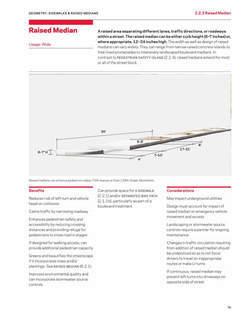
79
Benefits
Reduces risk of left-turn and vehicle head-on collisions
Calms traffic by narrowing roadway
Enhances pedestrian safety and accessibility by reducing crossing distances and providing refuge for pedestrians to cross road in stages
If designed for walking access, can provide additional pedestrian capacity
Greens and beautifies the streetscape if it incorporates trees and/or plantings. See RAISED MEDIAN (6.2.1)
Improves environmental quality and can incorporate stormwater source controls
Can provide space for a SIDEWALK (2.2.1) and/or SEPARATED BIKE PATH (2.1.1b), particularly as part of a boulevard treatment
GEOMETRY: SIDEWALKS & RAISED MEDIANS 2.2.3 Raised Median
Raised Median
Usage: Wide
A raised area separating different lanes, traffic directions, or roadways within a street. The raised median can be either curb height (6–7 inches) or, where appropriate, 12 – 24 inches high. The width as well as design of raised medians can vary widely. They can range from narrow raised concrete islands to tree-lined promenades to intensively landscaped boulevard medians. In contrast to PEDESTRIAN SAFETY ISLAND (2.2.4), raised medians extend for most or all of the street block.
Considerations
May impact underground utilities
Design must account for impact of raised median on emergency vehicle movement and access
Landscaping or stormwater source controls require a partner for ongoing maintenance
Changes in traffic circulation resulting from addition of raised median should be understood so as to not force drivers to travel on inappropriate routes or make U-turns
If continuous, raised median may prevent left turns into driveways on opposite side of street
Raised medians can enhance pedestrian safety: Fifth Avenue at East 138th Street, Manhattan
7–10'4'
17–21'
6–8'
35'
6–7" H
8'

80
Application
Two-way streets with two or more roadway travel lanes in total
Consider on all two-way multilane streets
On streets of limited width, it may be preferable in some situations to include other treatments (e.g., expanded sidewalks or dedicated transit or bicycle facilities) rather than a raised median if there is not adequate room for all treatments and travel lanes
Design
Raised medians should be wide enough to provide refuge to pedestrians at crossings: 5 feet minimum, 6 feet or greater preferred; when planted, 6 feet minimum. See RAISED MEDIANS (6.2.1)
Raised medians should extend beyond the crosswalk at intersections wherever possible, while accommodating vehicle turning movements; the “nose” of the raised median should include bollards to protect pedestrians from wayward vehicles
Provide a walkable path across the raised median at crossings. When the median is less than 17 feet wide, an 8 – 10-foot-wide cut-through, flush with the roadway, is appropriate. On medians wider than 17 feet, pedestrian ramps (1:12 grade with 5-foot landing areas) can be used to provide access
Provide a large pedestrian storage area at crossings to permit groups of pedestrians to safely wait to cross
Provide tactile cues for pedestrians with vision disabilities to indicate the border between the pedestrian refuge area and the motorized travel lanes
Include street trees, plantings, and unpaved or permeable surfaces wherever safe and feasible, using structural soil where appropriate. See TREE BEDS (6.1), RAISED MEDIAN
(6.2.1), and POROUS CONCRETE (3.1.13)
Grade roadways to direct stormwater towards raised medians if the raised medians include stormwater source controls, for example through the use of double or inverted roadway crown
If work includes tree planting, consider the location of utility infrastructure, including DEP sewers and water mains; also consider visibility for motorists, cyclists, and pedestrians
Raised medians must be designed so as to maintain drainage of stormwater and not cause ponding
Locate trees and/or plantings within raised median. See TREE BEDS (6.1) and RAISED MEDIAN (6.2.1)
Maximize permeable surface of raised median
Where feasible, design planted areas within raised median so as to capture stormwater according to current standards. See STORMWATER
MANAGEMENT PRACTICES (6.6)
2.2.3 Raised Median GEOMETRY: SIDEWALKS & RAISED MEDIANS
Median with Greenstreet and sidewalk: Carlton Avenue, Brooklyn

81
Benefits
Enhances pedestrian safety and accessibility by reducing crossing distances and providing refuge for pedestrians to cross road in stages
Calms traffic, especially left turns and through-movements, by narrowing roadway at intersection
Reduces risk of vehicle left-turn and head-on collisions at intersection
Can green and beautify the streetscape with trees and/or vegetation, potentially including stormwater source controls
Trees increase the visibility of the island, thereby usually improving safety
Considerations
May impact underground utilities
Landscaping or stormwater source controls require a partner for ongoing maintenance
Application
See application guidance for RAISED
MEDIAN (2.2.3)
Design
See design guidance for RAISED
MEDIAN (2.2.3)
Typical island accommodates two street trees and, where appropriate, bell bollards. See TREE BEDS (6.1) and RAISED MEDIAN (CURB HEIGHT)
(6.2.1a)
2.2.4 Pedestrian Safety IslandGEOMETRY: SIDEWALKS & RAISED MEDIANS
Pedestrian Safety Island Usage: Wide
A raised area located at crosswalks that serves as pedestrian refuge separating traffic lanes or directions, particularly on wide roadways. Also known as a “median refuge island” and “Green Refuge Island.” Used at pedestrian crossings when a full R AISED MEDIAN is not feasible. A pedestrian safety island confers most of the same benefits as full RAISED
MEDIANS at pedestrian crossings. Full RAISED MEDIANS should be used rather than pedestrian safety islands wherever possible.
LEFT: Pedestrian safety island: Crotona Avenue, Bronx
ABOVE: Pedestrian safety island: Hillside Avenue, Queens6–7" H
6–20'
Island tip alignswith curbs 35'
6-8'
Corner Radius = 3'4'
8'
7–10'

82
Benefits
Reduces or eliminates short-cut and cut-through traffic
When applied consistently to an area, reduces traffic speeds
Can green and beautify the streetscape with trees and/or vegetation, improving environmental quality and potentially incorporating stormwater source controls
Enhances safety at intersection by reducing potential vehicle movements and conflicts, particularly left turns
Reduces risk of vehicle head-on collisions
Reduces risk of motorists running a red light or stop sign when approaching from side street
Calms traffic on side street by requiring turn and on major street by narrowing roadway
Enhances pedestrian safety and accessibility by reducing crossing distances and providing refuge for pedestrians to cross the road in stages
Considerations
May impact street drainage or require catch basin relocation
May impact underground utilities
Emergency vehicle access needs must be accommodated
Landscaping or stormwater source controls require a partner for ongoing maintenance
2.2.5 Median Barrier GEOMETRY: SIDEWALKS & RAISED MEDIANS
Median Barrier Usage: Limited
A R AISED MEDIAN or PEDESTRIAN SAFET Y ISL AND extended through an intersection to prevent left turns and through-movements to and from the intersecting street. Pedestrian access can be maintained with pedestrian refuges and bicycle access with gaps in the median. As with typical RAISED
MEDIANS, trees or plantings can be included within the median barrier.
The raised median on Canal Street extends through the intersection with Washington Street: Manhattan.
If outfitted to capture stormwater, careful consideration must be given to design, overflow control, and plant species
Application
Consider on local streets with speeding or cut-through/short-cutting issues
One-way or two-way local streets at their intersections with two-way collector or arterial roadways
Design
Design traffic diversion devices to impact motor vehicle movement but not bicycle movement; utilize bike channels or similar design strategies to allow passage by bicyclists
Include planted areas and stormwater source controls within traffic diverters wherever possible when a maintenance partner is identified
If work includes tree planting, consider the location of utility infrastructure, including DEP sewers and water mains
Locate trees and/or plantings within diverter when appropriate. See TREE
BEDS (6.1) and RAISED MEDIAN (6.2.1)
Maximize permeable surface of diverter. See POROUS CONCRETE (3.1.13)
Design any planted areas within diverter so as to capture stormwater according to current standards
See additional design guidance for RAISED MEDIAN (2.2.3)

83
Geometry2.0 Introduction 2.3 Traffic CalmingGEOMETRY
Traffic Calming

84
Benefits
Reduces opportunities for speeding and aggressive driving, thereby decreasing the severity and frequency of crashes
Organizes the roadway to provide clearer instruction to drivers, cyclists, and pedestrians
Provides space for pedestrian refuge islands, assigned turn lanes, angle parking, wide parking lanes, bus lanes, bicycle lanes, expanded sidewalks/pedestrian space, or other uses
Considerations
Traffic conditions must be considered in planning lane removals; detailed analysis may be needed
Commercial loading and other uses should be considered in planning lane narrowing
Planned uses, such as bus lanes or bicycle lanes, should be taken into consideration
Effects of narrowings on turning movements should be tested
Application
Consider lane narrowings on corridors with excessively wide lanes
Multilane corridors with excess capacity (more traffic capacity than traffic volume) are excellent candidates for lane removal
Multi-lane corridors may be good candidates for lane removal in concert with other treatments, such as signal timing changes
Lane narrowing and removal should be prioritized on corridors with safety or speeding concerns, or where prioritization of non-general traffic is desirable
2.3.1 Lane Narrowing and Lane Removal
Lane Narrowing & Lane Removal Usage: Wide
Lane Narrowings remove excess width from existing moving lanes without changing the number of moving/traffic lanes. Lane Removals reassign underused traffic lanes to other functions. These design techniques, while not traffic-calming devices, have powerful traffic-calming benefits. Both may be accomplished by adding markings, turning lanes, pedestrian refuge islands, expanded pedestrian space, on-street or separated bicycle lanes, parking, or other functions.
Before: After two fatalities occurred at the same intersection in one year, DOT found that the roadway was over capacity: West 6th Street, Brooklyn
Design Guidelines
Lane narrowings and removals should result in standard-width lanes
When other treatments are included in a lane narrowing/removal, see specific guidelines for those treatments
CURB EXTENSION
After: DOT installed a "road diet" in 2010, resulting in a 25% reduction in crashes
GEOMETRY: TRAFFIC CALMING

85
GEOMETRY: TRAFFIC CALMING
Benefits
Compels drivers to travel at speeds no higher than the street’s design speed
A speed table can be used to provide a raised mid-block crossing in conjunction with a stop control
Considerations
Impacts emergency vehicle movement
Snow plows must be given advance warning
May generate additional noise
Application
Must be requested by a community, with approval based on a DOT field study of the location using speed survey, geometric, and street operations criteria
Avoid on streets that have any of the following characteristics:
o designated as “local” or “through” truck routes
o on MTA bus routes, tour-bus routes, or routes of any other bus operator
o emergency-vehicle response or snow emergency routes
o Fire Department house located on the block
o more than one moving lane per direction
o wider than 44 feet
The location can be investigated by DOT for a “Reduced School Speed Zone” if a speed reducer is not feasible but the street has an 85th percentile speed of 25 mph or higher and is near an eligible school
Design
Space raised speed reducers to maintain desired operating speeds
Appropriate warning signs and roadway markings should accompany raised speed reducers
Locate raised speed reducers in the middle of the roadway, with the gutters kept clear for proper road drainage
Use signage or other methods to alert operators of snow-clearing vehicles to the presence of raised speed reducers
While raised speed reducers (humps, tables, cushions) are an effective method to retrofit existing streets to reduce motor vehicle speeds in lieu of street reconstruction, all newly reconstructed streets should be comprehensively designed to achieve desired speeds, e.g., using appropriate roadway width and alignment, horizontal deflection, traffic controls, trees, and other traffic calming treatments
Utilize recycled content in paving materials
2.3.2 Raised Speed Reducer
Raised Speed Reducer Usage: Wide
A raised area of a roadway that deflects both the wheels and frame of a traversing vehicle with the purpose of reducing vehicle speeds. The two basic types of raised speed reducers are speed humps and speed tables. Both are typically raised 3 to 4 inches above the level of the roadway, and both have a proven speed-reducing track record in New York City. While a speed hump is relatively short in length (e.g., 13 feet long), a speed table is longer (e.g., 22 to 30 feet long), with a flat section in the middle, sometimes including a RAISED
CROSSWALK (2.3.4). SPEED CUSHION (2.3.2a) are a variation of speed humps designed to allow easier emergency vehicle, bus, or truck passage.
Speed hump: Bolton Avenue, Bronx

86
2.3.2a Raised Speed Reducer: Speed Cushion
Narrow speed humps that reduce traffic speeds without causing vertical displacement of vehicles with wide wheel bases (trucks, buses, and emergency vehicles). Wide vehicles can travel over speed cushions at moderate speed after aligning properly, making them potentially appropriate for use on streets with low- to moderate-frequency emergency, truck, or bus routes.
Benefits
See benefits of RAISED SPEED
REDUCERS (2.3.2)
Reduces motor vehicle speeds without hampering bus service or most commercial vehicles
Quieter than speed humps on commercial routes
Can be easily removed, relocated, or repositioned
Available as an off-the-shelf product
Considerations
Snow plows must be given advance warning
Application
See application guidance for RAISED
SPEED REDUCERS (2.3.2)
Streets that qualify for RAISED SPEED
REDUCERS, except for the presence of a truck, bus, or emergency vehicle route
Consider on non-arterial roadways with speeding concerns
Avoid on arterial roadways
Design
See design guidance for RAISED
SPEED REDUCERS (2.3.2)
Spacing and dimensions of speed cushions are typically similar to those of other RAISED SPEED REDUCERS
Speed Cushion Usage: Pilot
Speed cushions showing ease of bus passage: Vancouver, Canada (Credit: Richard Drdul) (Note: for illustrative purposes only)
Speed cushions showing impact on typical vehicles: Vancouver, Canada (Credit: Richard Drdul) (Note: for illustrative purposes only)
RAISED SPEED REDUCER
GEOMETRY: TRAFFIC CALMING

87
GEOMETRY: TRAFFIC CALMING
Benefits
Decreases vehicular speeds and discourages through-traffic without blocking or prohibiting vehicular access
Demarcates transitions to low-speed, SHARED STREET (2.1.3). or pedestrian-oriented areas
Provides pedestrians with priority movement across the treated leg of the intersection
Considerations
May impact street drainage or require catch basin relocation
May impact underground utilities
May require loss of curbside parking in some cases
Community facilities typically necessitate the presence of a maintenance partner
Many community facilities and sidewalk items require a permit or revocable consent from the city
If work includes tree planting, consider the location of utility infrastructure, including DEP sewers and water mains
Where feasible, design planted areas within gateway so as to capture stormwater according to current standards. See STORMWATER
MANAGEMENT PRACTICES (6.6)
If gateway includes PLANTED CURB
EXTENSIONS, see design guidance for PLANTED CURB EXTENSIONS (6.3.3)
2.3.3 Gateway
Gateway Usage: Limited
A combination of traffic-calming and visual measures used at the entrance to a low-speed street to slow entering vehicles and discourage through-traffic. Useful at all roadway transitions to slower-speed environments, gateways are especially suited to entrances to residential side streets and SHARED STREETS. The design elements of a gateway can include CURB EXTENSIONS (2.2.2), a RAISED CROSSWALK (2.3.4) or driveway treatment, a RAISED MEDIAN (2.2.3), landscaping or trees, and community facilities such as seating and public art.
LEFT: Gateway to residential street: West 11th Street at Seventh Avenue South, Manhattan
If gateway includes a RAISED
CROSSWALK (2.3.4), snow plows must be given advance warning
Application
Entrances to SHARED STREETS
Consider at entrances to streets with low vehicle volumes or speeds from streets with high vehicle volumes or speeds
Design
Include at a minimum CURB
EXTENSIONS (2.2.2) to narrow the roadway; preferably, vertical deflection should also be created using a RAISED CROSSWALK or ramped driveway treatment; if the street is two-way, a RAISED MEDIAN (2.2.3) or PEDESTRIAN SAFETY ISLAND (2.2.4) can be included, space permitting
Other design elements can “narrow” a street visually, including plantings, public art, bicycle parking, and community facilities such as seating
ABOVE: Gateway at transition from local residential street: Prospect Place, Brooklyn

88
GEOMETRY: TRAFFIC CALMING2.3.4 Raised Crosswalk
A marked pedestrian crosswalk at an intersection or a mid-block location constructed at a higher elevation than the adjacent roadway. A raised crosswalk is essentially a speed table, with the full width of the crosswalk contained within the flat portion of the table, usually 10- to 15-feet wide. It combines the benefits of a RAISED SPEED REDUCER (2.3.2) with enhanced visibility for the pedestrian crossing.
Raised Crosswalk
Usage: Limited
Benefits
Compels drivers to travel at speeds no higher than the street’s design speed
Improves drivers’ awareness of presence of pedestrian crossing, particularly at mid-block crossing locations
Used at street GATEWAYS (2.3.3), can alert drivers that they are entering a slower-speed, pedestrian-oriented street environment
Allows convenient pedestrian circulation between high foot traffic destinations on opposite sides of a street
Considerations
May impact street drainage or require catch basin relocation
Attention should be given to accommodation of and navigation by people with vision disabilities
Application
Existing stop-controlled crosswalks or other locations where demand exists for a stop-controlled pedestrian crossing that also meet the criteria for
RAISED SPEED REDUCERS (2.3.1)
Consider at areas of particularly high pedestrian crossing demand on narrower streets (maximum of two moving lanes), such as locations with pedestrian generators (e.g., major commercial or cultural destinations, transit entrances, parks) on opposite sides of the street
Consider as a more robust option for mid-block crossings
Consider on the outer roadways of multi-lane boulevards at crossings
Avoid on arterial roadways
Design
Appropriate warning signs and roadway markings should accompany raised crosswalk
Use signage or other methods to alert snow-clearing vehicle operators to the presence of raised crosswalk
Detectable warning strips with high color contrast from sidewalk surface should be provided at crosswalk location
Raised crosswalk: Paris, France (Note: for illustrative purposes only)
Raised crosswalk: London, United Kingdom (Note: for illustrative purposes only)
Use enhanced, high-visibility street materials to further draw attention to raised crosswalk
See design guidance for RAISED SPEED
REDUCERS (2.3.2)
Utilize recycled content in paving materials

89
Benefits
Forces drivers to drive more slowly and with greater awareness, particularly at mid-block locations
Can green and beautify the streetscape with trees and/or vegetation, improving environmental quality and potentially incorporating stormwater source controls
Considerations
May impact street drainage or require catch basin relocation
May impact underground utilities
May require loss of curbside parking
Landscaping or stormwater source controls require a partner for ongoing maintenance
If outfitted to capture stormwater, careful consideration must be given to design, overflow control, and plant species
May impact snow plows and street sweepers
Application
Consider on narrower, low-volume, local streets (maximum of two moving lanes) with demonstrated speeding issues
Avoid on bus routes, truck routes, and major bicycle routes
Design
The simplest and most basic approach to create a chicane is to alternate on-street parking (parallel or angled) from one side to the other; in this case, CURB EXTENSIONS (2.2.2) at the beginning and end of each grouping of parking
If utilizing CURB EXTENSIONS, see CURB EXTENSION section for general design considerations
Use vertical elements to alert drivers and snow plow operators to presence of chicanes
Locate trees and/or plantings within chicane curb extensions when appropriate. See TREE BEDS (6.1) and ROADWAY PLANTINGS (6.2)
Maximize permeable surface of chicane curb extensions
Where feasible, design planted areas within chicane curb extensions to capture stormwater according to current standards. See STORMWATER
MANAGEMENT PRACTICES (6.6)
GEOMETRY: TRAFFIC CALMING 2.3.5 Chicane
Chicane Usage: Pilot
A serpentine roadway alignment or series of staggered CURB EX TENSIONS
to encourage lower driving speeds through horizontal deflection. Chicanes discourage or make it impossible for drivers to drive in a straight line. This can reduce vehicular speeds.
LEFT: Chicane: Vancouver, Canada (Credit: Richard Drdul) (Note: for illustrative purposes only)
ABOVE: Chicane at entry to residential neighborhood: San Francisco, California (Credit: SF MTA) (Note: for illustrative purposes only)
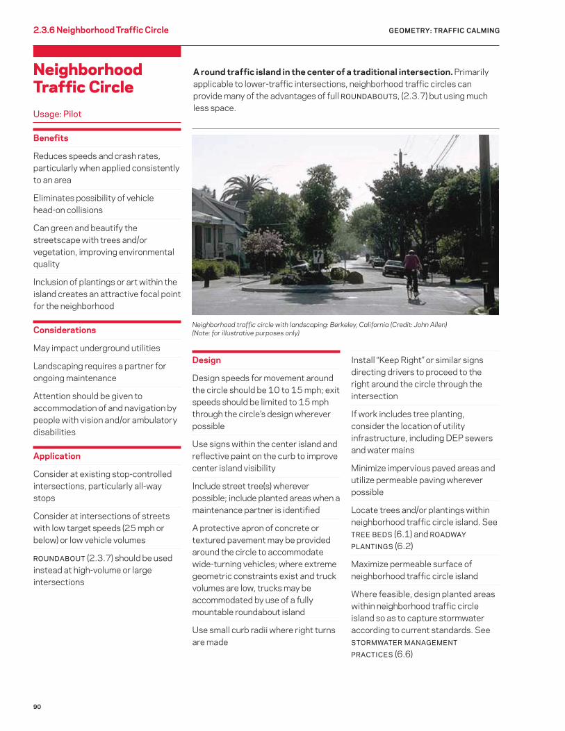
90
GEOMETRY: TRAFFIC CALMING2.3.6 Neighborhood Traffic Circle
A round traffic island in the center of a traditional intersection. Primarily applicable to lower-traffic intersections, neighborhood traffic circles can provide many of the advantages of full ROUNDABOUTS, (2.3.7) but using much less space.
Neighborhood Traffic CircleUsage: Pilot
Benefits
Reduces speeds and crash rates, particularly when applied consistently to an area
Eliminates possibility of vehicle head-on collisions
Can green and beautify the streetscape with trees and/or vegetation, improving environmental quality
Inclusion of plantings or art within the island creates an attractive focal point for the neighborhood
Considerations
May impact underground utilities
Landscaping requires a partner for ongoing maintenance
Attention should be given to accommodation of and navigation by people with vision and/or ambulatory disabilities
Application
Consider at existing stop-controlled intersections, particularly all-way stops
Consider at intersections of streets with low target speeds (25 mph or below) or low vehicle volumes
ROUNDABOUT (2.3.7) should be used instead at high-volume or large intersections
Design
Design speeds for movement around the circle should be 10 to 15 mph; exit speeds should be limited to 15 mph through the circle’s design wherever possible
Use signs within the center island and reflective paint on the curb to improve center island visibility
Include street tree(s) wherever possible; include planted areas when a maintenance partner is identified
A protective apron of concrete or textured pavement may be provided around the circle to accommodate wide-turning vehicles; where extreme geometric constraints exist and truck volumes are low, trucks may be accommodated by use of a fully mountable roundabout island
Use small curb radii where right turns are made
Install “Keep Right” or similar signs directing drivers to proceed to the right around the circle through the intersection
If work includes tree planting, consider the location of utility infrastructure, including DEP sewers and water mains
Minimize impervious paved areas and utilize permeable paving wherever possible
Locate trees and/or plantings within neighborhood traffic circle island. See TREE BEDS (6.1) and ROADWAY
PLANTINGS (6.2)
Maximize permeable surface of neighborhood traffic circle island
Where feasible, design planted areas within neighborhood traffic circle island so as to capture stormwater according to current standards. See STORMWATER MANAGEMENT
PRACTICES (6.6)
Neighborhood traffic circle with landscaping: Berkeley, California (Credit: John Allen) (Note: for illustrative purposes only)
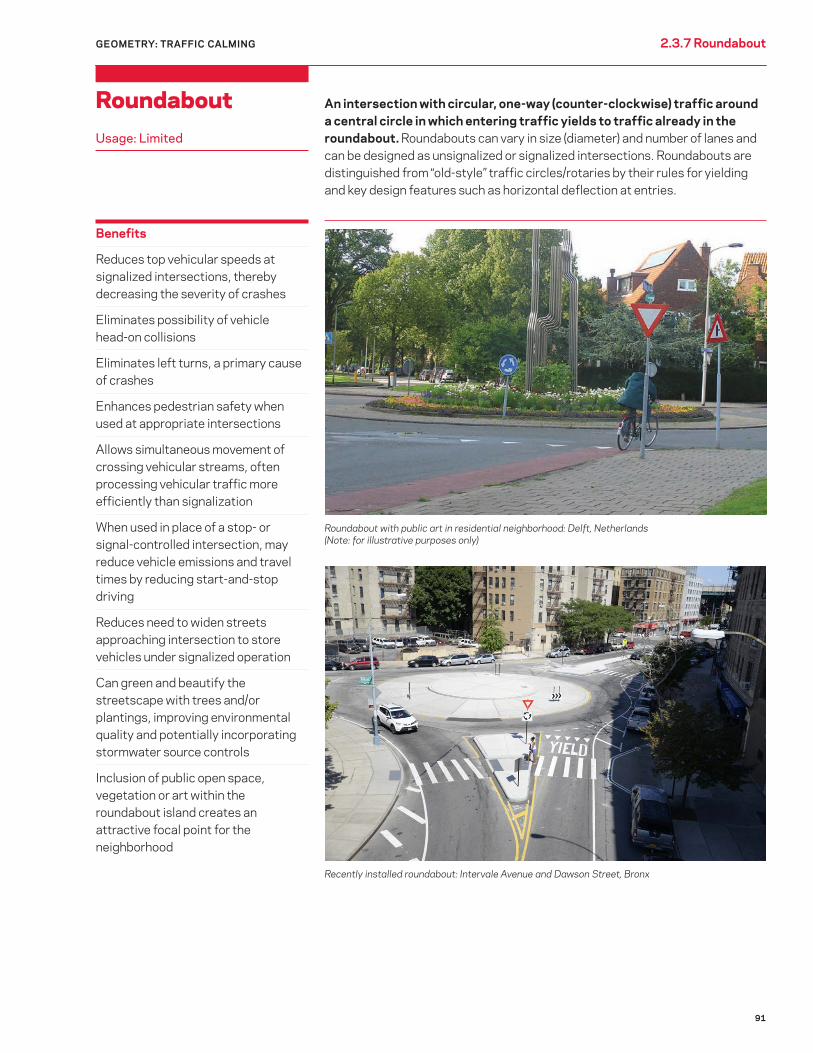
91
Benefits
Reduces top vehicular speeds at signalized intersections, thereby decreasing the severity of crashes
Eliminates possibility of vehicle head-on collisions
Eliminates left turns, a primary cause of crashes
Enhances pedestrian safety when used at appropriate intersections
Allows simultaneous movement of crossing vehicular streams, often processing vehicular traffic more efficiently than signalization
When used in place of a stop- or signal-controlled intersection, may reduce vehicle emissions and travel times by reducing start-and-stop driving
Reduces need to widen streets approaching intersection to store vehicles under signalized operation
Can green and beautify the streetscape with trees and/or plantings, improving environmental quality and potentially incorporating stormwater source controls
Inclusion of public open space, vegetation or art within the roundabout island creates an attractive focal point for the neighborhood
GEOMETRY: TRAFFIC CALMING 2.3.7 Roundabout
Roundabout Usage: Limited
An intersection with circular, one-way (counter-clockwise) traffic around a central circle in which entering traffic yields to traffic already in the roundabout. Roundabouts can vary in size (diameter) and number of lanes and can be designed as unsignalized or signalized intersections. Roundabouts are distinguished from “old-style” traffic circles/rotaries by their rules for yielding and key design features such as horizontal deflection at entries.
Roundabout with public art in residential neighborhood: Delft, Netherlands (Note: for illustrative purposes only)
Recently installed roundabout: Intervale Avenue and Dawson Street, Bronx
92
Considerations
May require increased spatial footprint for intersection, but not approaches
May impact street drainage or require catch basin relocation
May impact underground utilities
May require loss of curbside parking
Landscaping or stormwater source controls require a partner for ongoing maintenance
If outfitted to capture stormwater, careful consideration must be given to design, overflow control, and plant species
Attention should be given to accommodation of and navigation by people with vision and/or ambulatory disabilities
Application
Intersections with 1) no more than 80 – 90% of volume on the main facility and 2) having at least three approaches, high vehicle-turning volumes or percentages, or speeding issues
Consider at locations with poor safety records, or where signalization has led or may lead to operational issues for pedestrians or bicyclists
As a gateway treatment for low-speed (25 mph speed limit or less) or SHARED
STREETS (2.1.3)
2.3.7 Roundabout GEOMETRY: TRAFFIC CALMING
Design
Deflection should be created for entering vehicles to reinforce yielding behavior; at two-way legs of the intersection, use splitter islands to provide deflection as well as to allow pedestrians to cross in two segments
Detectable warning strips should be provided at all crosswalk locations with high color contrast from the sidewalk surface
Limit entry and exit speeds through deflection and/or raised crosswalks
Curves should accommodate the design vehicle; use an apron of textured paving around the central island to slow motor vehicle movements while accommodating larger vehicles such as trucks
To improve center island visibility, use reflective signs within the center island and reflective paint on the curb
Include street tree(s) wherever possible; include planted areas and stormwater source controls when a maintenance partner is identified
If work includes tree planting, consider the location of utility infrastructure, including DEP sewers and water mains
Minimize impervious paved areas and utilize permeable paving wherever possible
Locate trees and/or plantings within roundabout islands. See TREE BEDS (6.1) and ROADWAY PLANTINGS (6.2)
Maximize permeable surface of roundabout islands
Where feasible, design planted areas within roundabout islands so as to capture stormwater according to current standards. See STORMWATER
MANAGEMENT PRACTICES (6.6)

93
2.3.8 Raised IntersectionGEOMETRY: TRAFFIC CALMING
An entire intersection raised above the level of the surrounding roadways. The intersection is typically raised to sidewalk height.
Raised Intersection Usage: Pilot
Benefits
Vertical deflection at entry to intersection encourages reduced vehicle speeds
Improves drivers’ awareness of presence of crossings
Visually turns intersection into a pedestrian-oriented zone
Enhances access for people with disabilities
Considerations
May impact street drainage or require catch basin relocation
Snow plows must be given advance warning
Application
Stop-controlled intersections with a high volume of pedestrian crossings and low target vehicle speeds (e.g., 25 mph or below)
Stop-controlled intersections with a history of pedestrian crashes or speeding issues
Stop-controlled intersections where enhancing pedestrian movement is a major goal, such as transit stops or commercial areas
Avoid on truck routes and at other locations where RAISED SPEED
REDUCERS (2.3.2) are not appropriate
Design
Slope of entrance ramps for motorized traffic can be steep or shallow, depending on target speeds
Use enhanced, high-visibility street materials to further draw attention to raised intersection
Minimize impervious paved areas and utilize permeable paving wherever possible
Increase SRI value of paved surfaces to reduce urban heat island impact
Utilize recycled content in paving materials
Coordinate streetscape/utility work to minimize street cuts
LEFT: Raised intersection: Cambridge, Massachusetts (Credit: Cara Seiderman)
ABOVE: Raised intersection: London, United Kingdom (Note: for illustrative purposes only)