
STRATO EVO 40W LED DRIVER - efore.cdistore.com · • Programmable Output Current Settings •...
12
CONSTANT CURRENT, 0-10V DIMMABLE RTLD040-1400A-SA-RF STRATO EVO 40W LED DRIVER www.efore.com Page 1 DS1_RTLD040-1400A-SA-RF Rev 00, May 2018 PRELIMINARY APPLICATIONS AND BENEFITS STRATO EVO 40W is designed for directly powering LEDs in commercial & industrial lighting applications. The product’s extremely small form factor and high efficiency makes it suitable for integration into most light fixtures and standard electrical junction boxes. A host of integrated control features: • Simplify Light Fixture Design • Ease Safety Approval Cycles • Lower Fixture Complexity and Cost DESCRIPTION STRATO EVO 40W switch mode driver technology is designed to generate one constant current output from a wide range AC input. The size and performance of these products make them the ideal choice for LED lighting applications. KEY FEATURES • Wide Input Range: 120/220-240/277V AC • Constant Current Output • Flicker Free • Low dimming level (1%) • IP 64 • Low Standby power consumption <0.5W • High Efficiency up to 88% • Easily programmed via RFID (RF models) wireless or wired tools • Programmable Output Current Settings • Dimmable with 1-10V / 0-10V Dimmers. Dim to OFF (DTO) • Temperature sensor input (NTC) to protect the LED • Convection Cooled • Class 2 Output, Class II isolation • Wide Operating Temperature Range -30°C up to 90°C TC • 8-year warranty under useful life condition LED Module Temp Sensor NTC 10k or 100k AC Input STRATO EVO LED Driver +Dim - Dim + LED Ts - LED 0-10V/1-10V Dimmer or Variable Resistor ~ (1-10VDC) Source STRATO EVO’s versatile control features: • A Temperature sensor (NTC thermistor) protects the LED from over-temperature. The NTC can be either a 10kΩ or 100kΩ • A 2 wire Dimming input provides both output trimming, and 1 to 100% Iout Dimming function.
Transcript of STRATO EVO 40W LED DRIVER - efore.cdistore.com · • Programmable Output Current Settings •...

CONSTANT CURRENT, 0-10V DIMMABLE
RTLD040-1400A-SA-RF STRATO EVO 40W LED DRIVER
www.efore.com Page 1 DS1_RTLD040-1400A-SA-RF Rev 00, May 2018
PRELIMINARY
APPLICATIONS AND BENEFITS
STRATO EVO 40W is designed for directly powering LEDs in commercial & industrial lighting applications.
The product’s extremely small form factor and high efficiency makes it suitable for integration into most light fixtures and standard electrical junction boxes.
A host of integrated control features:
• Simplify Light Fixture Design
• Ease Safety Approval Cycles
• Lower Fixture Complexity and Cost
DESCRIPTION
STRATO EVO 40W switch mode driver technology is designed to generate one constant current output from a wide range AC input. The size and performance of these products make them the ideal choice for LED lighting applications.
KEY FEATURES
• Wide Input Range: 120/220-240/277VAC
• Constant Current Output
• Flicker Free
• Low dimming level (1%)
• IP 64
• Low Standby power consumption <0.5W
• High Efficiency up to 88%
• Easily programmed via RFID (RF models) wireless or wired tools
• Programmable Output Current Settings
• Dimmable with 1-10V / 0-10V Dimmers. Dim to OFF (DTO)
• Temperature sensor input (NTC) to protect the LED
• Convection Cooled
• Class 2 Output, Class II isolation
• Wide Operating Temperature Range -30°C up to 90°C TC
• 8-year warranty under useful life condition
LED Module
Temp Sensor NTC
10k or 100k
AC
Input
STRATO EVO
LED Driver
+Dim
- Dim
+ LED
Ts
- LED
0-10V/1-10V Dimmer
or Variable Resistor
~
(1-10VDC) Source STRATO EVO’s versatile control features:
• A Temperature sensor (NTC thermistor) protects the LED from over-temperature. The NTC can be either a 10kΩ or 100kΩ
• A 2 wire Dimming input provides both output trimming, and 1 to 100% Iout Dimming function.

CONSTANT CURRENT, 0-10V DIMMABLE
RTLD040-1400A-SA-RF STRATO EVO 40W LED DRIVER
www.efore.com Page 2 DS1_RTLD040-1400A-SA-RF Rev 00, May 2018
PRELIMINARY
MODEL CODING AND OUTPUT RATINGS
Model number Case Dimming RFID
Programming Pout Max
(W) Vout Min
(VDC) Vout Max
(VDC) Iout Programmable range
(mA) RTLD040-1400A-SA-RF S Case 0-10V Yes 39.2 20 43 200 1400 RTLD040-1400A-SA S Case 0-10V NO 39.2 20 43 200 1400
Table 1: Absolute Maximum Driver Ratings
OUTPUT RATING GRAPHS
Iout Programmable range

CONSTANT CURRENT, 0-10V DIMMABLE
RTLD040-1400A-SA-RF STRATO EVO 40W LED DRIVER
www.efore.com Page 3 DS1_RTLD040-1400A-SA-RF Rev 00, May 2018
PRELIMINARY
INPUT SPECIFICATION
Specification Test Conditions / Notes Min Nom Max Units
AC Input Voltage 120/220-240/277VAC Device starts and operates at 90VAC at all load conditions
90 120/220-240/277 305 VAC
Input Frequency 47 50/60 63 Hz
Input Current 120VAC Rated Load 230VAC Rated Load 277VAC Rated Load
- - -
- - -
0.39 0.20 0.17
A
Power Factor
120VAC Rated Load (30-100%) 230VAC Rated Load (50-100%) 277VAC Rated Load (60-100%)
0.9 0.9 0.9
0.98 0.97 0.94
- - -
THD 120VAC Rated Load (30-100%) 230VAC Rated Load (50-100%) 277VAC Rated Load (60-100%)
- - -
9 14 15
20 20 20
%
Inrush Current 120VAC Half Value time: 120µs 230VAC Half Value time: 95µs 277VAC Half Value time: 95µs
- - -
- - -
16 43 47
Apk
Efficiency 120VAC Rated Load 230VAC Rated Load 277VAC Rated Load
- - -
86 87 88
- - -
%
Harmonic Current Complies with EN-61000-3-2, Class C load >25W
OUTPUT SPECIFICATIONS
Specification Test Conditions / Notes Min Nom Max Units Output Power Rating - - 39.2 W
Output Voltage 20 - 43 V
Output Current Programmable range 200 - 1400 mA Minimum dimming level 3 6 9 mA Ripple Current_HF High frequency (@40kHz) IoutPk-pk/IoutRMS - - 10 % Ripple Current_LF Low frequency <1kHz ±1 % Stand by Power - - 0.5 W Output Regulation - ±5 %Iout Start-up time With no dimmer connected - 300 500 ms
PROTECTION FEATURES
Specification Test Conditions / Notes Min Nom Max Units Output Over Voltage Unit shuts Down and latches off after 4 attempts 110 - 130 %VMAX Output Short-Circuit Unit shuts Down and latches off after 4 attempts - - - - Over-Temperature Tc Power derating, auto Recovery if the PSU exceeds the rated Tc temperature 90 °C No Load Unit shuts Down and latches off after 4 attempts Isolation Primary-to-Secondary Reinforced/double Insulation meets IEC/EN61347-2-13 Class II

CONSTANT CURRENT, 0-10V DIMMABLE
RTLD040-1400A-SA-RF STRATO EVO 40W LED DRIVER
www.efore.com Page 4 DS1_RTLD040-1400A-SA-RF Rev 00, May 2018
PRELIMINARY
CONTROLS
Output Controls: Two dedicated inputs provide control and safety features. Dim: A dimming input can be used to adjust the output setting via a standard commercial wall dimmer, an external control voltage source (1 to 10VDC), or a variable resistor from 100% to 1% dimming. This permits active control of the driver dimming level. Ts: The Temperature input may be connected to a 100kΩ or 10kΩ NTC thermistor. The thermistor should be located on the LED assembly to monitor its temperature. If the temperature exceeds a predetermined set point, the output current of the module is automatically reduced to regulate the temperature of the LED at a safe level.
INRUSH CURRENT DATA
Due to its limited Inrush Current peak at power on, Strato EVO 40W LED driver makes easier the selection of overcurrent protection devices such as circuit breakers. Referring to the different kinds of Circuit Breakers available on the market, the maximum number of connectable Strato EVO 40W drivers is reported in the following table for each nominal input voltage.
Inrush Current Data # drivers for each Circuit Breaker
Vin Nominal
I peak (A)
Half Value Time (µs)
Type B
10A Type B
16A Type C
10A Type C
16A Type D
10A Type D
16A
120VAC 16.0 120 46 74 77 123 154 247
230VAC 42.5 100 21 34 35 56 70 113
277VAC 46.8 100 19 30 31 50 63 101
STAND-BY POWER CONSUMPTION
Strato EVO 40W LED Driver offers a low stand-by power consumption when the LEDs are switched off using the 0-10V dimmer option or the push dimmer option. When a DALI driver is used, the LEDs can be switched off from the DALI port (using the DALI off command). The Analog driver, programmed with 0-10V option, can switch off the LEDs when the dimmer voltage is below 0.8V. The typical stand-by power consumption is reported in the following table for each nominal input voltage.
Vin Nominal
Stand-by Power consumption
(W)
120VAC 0.25
230VAC 0.35
277VAC 0.45

CONSTANT CURRENT, 0-10V DIMMABLE
RTLD040-1400A-SA-RF STRATO EVO 40W LED DRIVER
www.efore.com Page 5 DS1_RTLD040-1400A-SA-RF Rev 00, May 2018
PRELIMINARY
LIFETIME VERSUS TOP CASE TEMPERATURE
The Strato EVO 40W has been designed to achieve 100kh of Life Time when operating at 75-80°C TC case, at full load, nominal line voltages. The maximum operating ambient temperature of the driver family is 60°C.
The following graphs are representative of the lifetime expectation for the Strato EVO 40W Led Driver Series. The curves have been evaluated in standard operative conditions.
RTLD040-1400A 120VAC Full/Half load
RTLD040-1400A 230VAC Full/Half load
RTLD040-1400A 277VAC Full/Half load

CONSTANT CURRENT, 0-10V DIMMABLE
RTLD040-1400A-SA-RF STRATO EVO 40W LED DRIVER
www.efore.com Page 6 DS1_RTLD040-1400A-SA-RF Rev 00, May 2018
PRELIMINARY
PROGRAMMABILITY
Strato EVO 40W provides 2 methods to program the output characteristics; wireless and wired. Similar features can be programmed through each method. Wireless: RFID technology is used to enable true wireless programming of the features without the need to energize or connect the driver to test equipment. A compatible RFID reader and EFORE software is required. Two pad reader options are available. A single driver pad reader is handheld and suitable to program individual drivers. The multiple driver pad reader will program a box of Strato EVO 40W LED Drivers simultaneously, without opening the box. Wired: All models can also be programmed with the Ozone Programming Tool (RSOZ070-PTOOL) for backward compatibility.
Single driver pad reader Order Code: ROALSET-Single
Multiple driver pad reader Order Code: ROALSET-Multi
Ozone Programming Tool Order Code: RSOZ070-PTOOL

CONSTANT CURRENT, 0-10V DIMMABLE
RTLD040-1400A-SA-RF STRATO EVO 40W LED DRIVER
www.efore.com Page 7 DS1_RTLD040-1400A-SA-RF Rev 00, May 2018
PRELIMINARY
OZONE PROGRAMMING TOOL (AVAILABLE AS OPTIONAL)
Strato EVO 40W can be easily set by the customer, for this reason they are extremely flexible and suitable for several applications. For this purpose, an external Module (Ozone Programming Tool) is available as optional and can be ordered separately specifying its Ordering Code7. This external module is designed to be connected to the Strato EVO LED Driver output. The Programming Tool is powered by a long-life battery; it is safe and easy to use; therefore, no particular technical skills are required to set the product. The Ozone Programming Tool allows you to set the output current value (Current Setting) and to enable other functionalities (Fade Time Setting, NTC Value 10kΩ or 100kΩ).
Note 7: The Ordering Code for the Ozone Programming Tool is RSOZ070-PTOOL. The 3-wire programming cable represented in the figure and a USB cable (for PC connection) are included with the Tool.
PROGRAMMING TOOL CONNECTION
The Ozone Programming Tool is easily connectable with Strato EVO LED Driver by the 3-wire cable provided together with the tool. The programming wires are identified by colored collars placed near the metal end terminals. Follow the connection table below for a correct programming connections correspondence between programming wires and Strato EVO outputs.
MECHANICAL DIMENSIONS AND BATTERY REPLACEMENT
Strato EVO Connection Programming Wire
TS orange RED collar wire -DIM grey BLACK wire +DIM purple WHITE collar wire
Table 2: Programming Tool Connection
Ozone Programming Tool (RSOZ070-PTOOL):
Dimensions: 80 x 55 x 19mm (3.15 x 2.16x0.75in)
Weight: 75gr (2.64oz)
3-wire Programming Cable length 750mm (29.5in)
CR1632 3V Lithium Battery Rated Capacity 125 mAh
USB connector
80mm
55mm
19mm Battery inside. Remove the plastic foil

CONSTANT CURRENT, 0-10V DIMMABLE
RTLD040-1400A-SA-RF STRATO EVO 40W LED DRIVER
www.efore.com Page 8 DS1_RTLD040-1400A-SA-RF Rev 00, May 2018
PRELIMINARY
CURRENT SETTING
The Current value can be easy set also by the customer using the Ozone Programming Tool, by moving 2 rotary switches (R1= Rotary 1, R2=Rotary 2), 10 positions each. The Table below shows the current set values (ISET) and the LED Driver Output Voltage Range, according to the positions of the Rotary Switches.
ISET Rotary VOUT Min VOUT Max ISET Rotary VOUT Min VOUT Max Notes
mA R1 - R2 VDC VDC mA R1 - R2 VDC VDC
0-0 600 5-0 20 43
STRATO EWO 40W is factory pre-set to the following values: ISET = 1400mA for RTLD040-1400A-SA-XX
0-1 610 5-1 20 43 0-2 620 5-2 20 43 0-3 630 5-3 20 43 0-4 640 5-4 20 43 0-5 650 5-5 20 43 0-6 660 5-6 20 43 0-7 670 5-7 20 43 0-8 680 5-8 20 43 0-9 690 5-9 20 43
200 1-0 20 43 700 6-0 20 43
210 1-1 20 43 710 6-1 20 43 220 1-2 20 43 720 6-2 20 43 230 1-3 20 43 730 6-3 20 43 240 1-4 20 43 740 6-4 20 43 250 1-5 20 43 750 6-5 20 43 260 1-6 20 43 760 6-6 20 43 270 1-7 20 43 770 6-7 20 43 280 1-8 20 43 780 6-8 20 43 290 1-9 20 43 790 6-9 20 43 300 2-0 20 43 800 7-0 20 43
310 2-1 20 43 810 7-1 20 43 320 2-2 20 43 820 7-2 20 43 330 2-3 20 43 830 7-3 20 43 340 2-4 20 43 840 7-4 20 43 350 2-5 20 43 850 7-5 20 43 360 2-6 20 43 860 7-6 20 43 370 2-7 20 43 870 7-7 20 43 380 2-8 20 43 880 7-8 20 43 390 2-9 20 43 890 7-9 20 43 400 3-0 20 43 900 8-0 20 43
410 3-1 20 43 910 8-1 20 43
420 3-2 20 43 920 8-2 20 42
430 3-3 20 43 930 8-3 20 42
440 3-4 20 43 940 8-4 20 41
450 3-5 20 43 950 8-5 20 41
460 3-6 20 43 960 8-6 20 40
470 3-7 20 43 970 8-7 20 40
480 3-8 20 43 980 8-8 20 40
490 3-9 20 43 990 8-9 20 39
500 4-0 20 43 1000 9-0 20 39
510 4-1 20 43 1050 9-1 20 37
520 4-2 20 43 1100 9-2 20 35
530 4-3 20 43 1150 9-3 20 34
540 4-4 20 43 1200 9-4 20 32
550 4-5 20 43 1250 9-5 20 31
560 4-6 20 43 1300 9-6 20 30
570 4-7 20 43 1350 9-7 20 29
580 4-8 20 43 1400 9-8 20 28
590 4-9 20 43 1400 9-9 20 28
Table 4: Rotary Switch settings combinations
CONSTANT CURRENT, 0-10V DIMMABLE
RTLD040-1400A-SA-RF STRATO EVO 40W LED DRIVER
www.efore.com Page 9 DS1_RTLD040-1400A-SA-RF Rev 00, May 2018
PRELIMINARY
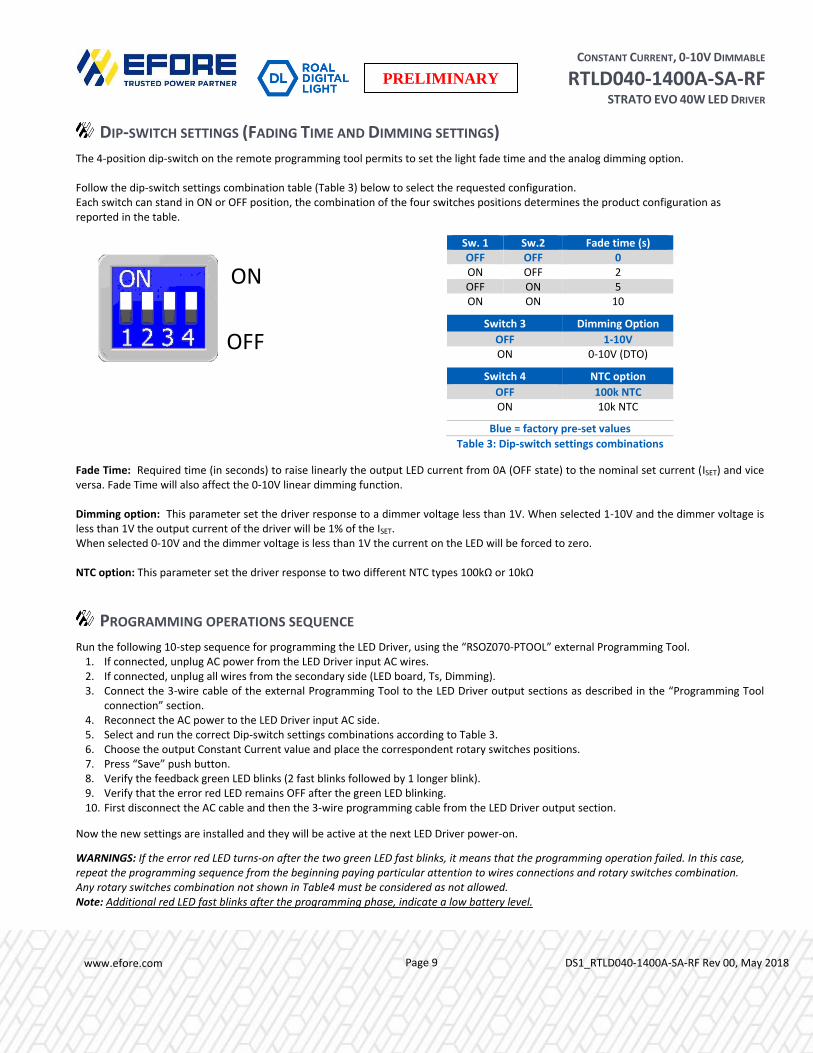
DIP-SWITCH SETTINGS (FADING TIME AND DIMMING SETTINGS)
The 4-position dip-switch on the remote programming tool permits to set the light fade time and the analog dimming option. Follow the dip-switch settings combination table (Table 3) below to select the requested configuration. Each switch can stand in ON or OFF position, the combination of the four switches positions determines the product configuration as reported in the table.
Fade Time: Required time (in seconds) to raise linearly the output LED current from 0A (OFF state) to the nominal set current (ISET) and vice versa. Fade Time will also affect the 0-10V linear dimming function. Dimming option: This parameter set the driver response to a dimmer voltage less than 1V. When selected 1-10V and the dimmer voltage is less than 1V the output current of the driver will be 1% of the ISET. When selected 0-10V and the dimmer voltage is less than 1V the current on the LED will be forced to zero. NTC option: This parameter set the driver response to two different NTC types 100kΩ or 10kΩ
PROGRAMMING OPERATIONS SEQUENCE
Run the following 10-step sequence for programming the LED Driver, using the “RSOZ070-PTOOL” external Programming Tool. 1. If connected, unplug AC power from the LED Driver input AC wires. 2. If connected, unplug all wires from the secondary side (LED board, Ts, Dimming). 3. Connect the 3-wire cable of the external Programming Tool to the LED Driver output sections as described in the “Programming Tool
connection” section. 4. Reconnect the AC power to the LED Driver input AC side. 5. Select and run the correct Dip-switch settings combinations according to Table 3. 6. Choose the output Constant Current value and place the correspondent rotary switches positions. 7. Press “Save” push button. 8. Verify the feedback green LED blinks (2 fast blinks followed by 1 longer blink). 9. Verify that the error red LED remains OFF after the green LED blinking. 10. First disconnect the AC cable and then the 3-wire programming cable from the LED Driver output section.
Now the new settings are installed and they will be active at the next LED Driver power-on.
WARNINGS: If the error red LED turns-on after the two green LED fast blinks, it means that the programming operation failed. In this case, repeat the programming sequence from the beginning paying particular attention to wires connections and rotary switches combination. Any rotary switches combination not shown in Table4 must be considered as not allowed. Note: Additional red LED fast blinks after the programming phase, indicate a low battery level.
Sw. 1 Sw.2 Fade time (s) OFF OFF 0 ON OFF 2 OFF ON 5 ON ON 10
Switch 3 Dimming Option
OFF 1-10V ON 0-10V (DTO)
Switch 4 NTC option
OFF 100k NTC ON 10k NTC
Blue = factory pre-set values
Table 3: Dip-switch settings combinations
ON
OFF

CONSTANT CURRENT, 0-10V DIMMABLE
RTLD040-1400A-SA-RF STRATO EVO 40W LED DRIVER
www.efore.com Page 10 DS1_RTLD040-1400A-SA-RF Rev 00, May 2018
PRELIMINARY
MECHANICAL DETAILS
Packaging: Polycarbonate (PC), UL94 V-0
Color: Black RAL 9005
I/O Connections: Flying leads
Input wires: n°2 wires 18 AWG 105°C rated (L/N), double insulation wire (Black/White), stranded, 152mm long
Output wires n°2 wires 18 AWG 105°C rated (LED+/LED-), stranded, 152mm long
Control wires n°3 wires 22 AWG 105°C rated (+DIM/-DIM/Ts), stranded, 152mm long
All wires are stripped by approximately 9.5mm and tinned.
Ingress Protection: IP64
Mounting Details: 2 mounting locations
OUTLINE DRAWINGS
Package: RTLD040 Box: Carton Box Dimensions: 78 x 40 x 27mm Dimensions: 32 x 26 x 7.5cm 3.07 x 1.57 x 1.06in 12.6 x 10.2 x 2.9in Volume: 84.2cm3, 5.1in3 Units per Box: 20 pcs Mass: 170g, (6.0oz) Mass: 3.8kg (83.77lb)

CONSTANT CURRENT, 0-10V DIMMABLE
RTLD040-1400A-SA-RF STRATO EVO 40W LED DRIVER
www.efore.com Page 11 DS1_RTLD040-1400A-SA-RF Rev 00, May 2018
PRELIMINARY
ENVIRONMENTAL SPECIFICATIONS
Specification Test Conditions / Notes Min Nom Max Units Top Case Temperature Range Top case temperature without derating -30 - 90 °C Ambient Temperature Range As long as Tc temperature is within the limits -30 - 60 °C Storage Temperature Relative Humidity 95% non-condensing -30 - 90 °C Operating Relative Humidity Non-condensing 5 - 95 % Surface Temperature Exposed surfaces temperature under all operating conditions - - 90 °C Cooling Convection cooled
Shock EN 60068-2-27 Operating: Half sine 30g/18ms, 3 axes, 6x each (3 positive and 3 negative) Non-Operating: Half sine, 50g/11ms, 3 axes, 6x each (3 positive and 3 negative)
Vibration EN 60068-2-64 Operating: 5-500Hz, 1gRMS (0.02 g2/Hz), 3 axes, 30 min Non-Operating: 5-500Hz, 2.46gRMS (0.0122 g2/Hz), 3 axes, 30 min
Vibration EN 60068-2-6 Operating Sine, 10-500Hz, 1g, 3 axes, 1 Oct/min., 60 min MTBF MAX Load, 40°C Ambient, Telcordia SR-332 Issue 2, D 80%. - 500k - Hours Useful Life Nominal 40°C Typical Nominal VAC, 75°C Tc Nominal Load - 100k - Hours
ELECTROMAGNETIC COMPATIBILITY (EMC) – EMISSIONS
Phenomenon Conditions / Notes Standard Performance Class Conducted Emission Test at 120VAC
Test at 230VAC Test at 277VAC
FCC CFR47- part 15 / Subpart B EN55015 FCC CFR47- part 15 / Subpart B
Class B -
Class A Radiated Emission Test at 120VAC
Test at 230VAC Test at 277VAC
FCC CFR47- part 15 / Subpart B EN55015 FCC CFR47- part 15 / Subpart B
Class B -
Class A Harmonic Current Emissions EN61000-3-2 Class C Voltage Changes, Fluctuation and Flicker EN61000-3-3
ELECTROMAGNETIC COMPATIBILITY (EMC) – IMMUNITY
Phenomenon Conditions / Notes Standard Note Equipment for general lighting purposes - EMC Immunity Requirements EN61547 ESD (Electrostatic Discharge) 8kV air, 4kV contact EN61000-4-2 Radiated Radio-Frequency electromagnetic field EN61000-4-3 Electric Fast Transient / Burst Level ±1.0kV L-L EN61000-4-4 Surge Level ±2.0kV L-L EN61000-4-5 Conducted disturbances induced by Radio-Frequency fields EN61000-4-6 Power Frequency Magnetic Field Test EN61000-4-8 Voltage Dips, short interruptions and Voltage Variations EN61000-4-11 Non-repetitive damped oscillatory transient, Ring wave 2.5kV ANSI C.62.41 Category A1

CONSTANT CURRENT, 0-10V DIMMABLE
RTLD040-1400A-SA-RF STRATO EVO 40W LED DRIVER
www.efore.com Page 12 DS1_RTLD040-1400A-SA-RF Rev 00, May 2018
PRELIMINARY
SAFETY AGENCY APPROVALS Certification Body Safety Standards
UL Recognized ANSI / UL8750, 1st Ed., CSA C22.2 No.250.0-08 Models with output voltages <60VDC include UL and CSA approval (cURus) as Class 2 output LED Driver suitable for dry and damp location
IEC/EN 62384 Electronic control gear for LED modules – Performance Requirements. IEC/EN, 61347-1, IEC/EN 61347-2-13 Electronic control gear for LED Modules – Safety
Directive 2014/35/EU (Electrical Safety: low-voltage electrical equipment- LVD) Directive 2014/30/EU (Electromagnetic Compatibility - EMC) Directive 2009/125/EC (EcoDesign) Commission Regulation(EU) No.1194/2012 Directive 2011/65/EU (RoHS 2) To obtain the “CE Declaration of Conformity” please contact [email protected]
IECEE CB Certified, IEC/EN, 61347-1, IEC/EN 61347-2-13 electronic control gear for LED Modules. All models are isolated control gears, SELV equivalent, with internal reinforced insulation as per IEC/EN 61347-2-13. Drivers to be incorporated in the luminaire
GB19510.1-2009, GB19510.14-2009, GB17625.1-2012, GB/T17743-2007
Reinforced/double Insulation meets IEC/EN61347-2-13 Class II
PRODUCT FAMILY INFORMATION
Specifications appearing in EFORE’s catalogues and brochures as well as any oral statements are not binding. All descriptions, drawings and other particulars (including dimensions, materials and performance data) given by EFORE are as accurate as possible but, being given for general information, and are not binding on EFORE. EFORE makes thus no representation or warranty as to the accuracy of such material. We assume no liability other than as agreed in the terms of the individual contracts and we reserve the right to make technical modifications in the course of our product development. Our product information solely describes our goods and services and is in no way to be construed or interpreted as a quality or condition guarantee. The aforesaid shall not relieve the customer of its obligation to verify the suitability of our Products for the use or application intended by the purchaser. Customers are responsible for their products and applications. EFORE assumes no liability from the use of its products outside of specifications. No license is granted to any intellectual property rights by this document.
MODEL NUMBER RATING
PR
OD
UC
T
SELE
CTI
ON
GU
IDE
Model OptionRFID
ProgramCase
Dimming
Option
Pout Max
(W)
Vout Min
(VDC)
Vout Max
(VDC)
Iout Min
(mA)
Iout Max
(mA)
RTLD040-900A -SA Blank or -RF S Case 0-10V 39.2 25 56 150 900
RTLD040-900A -DA -RF only D Case 0-10V & Push 39.2 25 56 150 900
RTLD040-900A -DD -RF only D Case DALI 39.2 25 56 150 900
RTLD040-1400A -SA Blank or -RF S Case 0-10V 39.2 20 43 200 1400
RTLD040-1400A -DA -RF only D Case 0-10V & Push 39.2 20 43 200 1400
RTLD040-1400A -DD -RF only D Case DALI 39.2 20 43 200 1400
RTLP040-24 -S Blank only S Case ON-OFF 36.0 - 24 - 1500
RTLP040-24 -D Blank only D Case ON-OFF 36.0 - 24 - 1500
RTLP040-48 -S Blank only S Case ON-OFF 36.0 - 48 - 750
RTLP040-48 -D Blank only D Case ON-OFF 36.0 - 48 - 750
CONSTANT CURRENT MODELS
CONSTANT VOLTAGE MODELS


![Syllabus - FCL/DTO/Programi... · Web viewThis syllabus, produced by DTO [enter name of DTO] for Balloon Pilot Licence (BPL), conforms to the requirements of the Part FCL. The purpose](https://static.fdocuments.in/doc/165x107/5eae8f25acd2b446175906e7/syllabus-fcldtoprogrami-web-view-this-syllabus-produced-by-dto-enter.jpg)


