Strategic plan for the facility for the next five years.
39
Future 7.iv pg. 1 7.iv. Strategic plan for the facility for the next five years. Executive Summary ............................................................................................................................................ 2 1) New Instrumentation Initiatives ..................................................................................................................... 4 a. Macromolecular Femtosecond Crystallography (MFX) Instrument in Hutch 4.5 ........................................... 4 b. Serial Sample Chamber (SSC) for CXI ........................................................................................................... 5 c. XCS Upgrade............................................................................................................................................... 6 d. Beam Sharing ............................................................................................................................................. 7 e. Detector Program....................................................................................................................................... 9 f. Rapid Data Analysis ................................................................................................................................... 11 2) New Beam Capabilities ................................................................................................................................. 13 a. Multi-Color X-Ray Beam Modes ................................................................................................................ 13 b. Soft X-Ray Self-Seeding............................................................................................................................. 17 c. Soft X-Ray Polarization.............................................................................................................................. 18 d. Electron Energy Stability........................................................................................................................... 19 e. XTCAV ...................................................................................................................................................... 20 3) Efficiency ..................................................................................................................................................... 22 a. Linac Infrastructure Mission Readiness ..................................................................................................... 22 b. Commonality of Controls/DAQ ................................................................................................................. 24 c. Prioritization Process, WBS Structure ........................................................................................................ 24 d. Cross Training of Staff .............................................................................................................................. 25 4) Support Facilities.......................................................................................................................................... 26 a. Laser ........................................................................................................................................................ 26 b. Sample Preparation.................................................................................................................................. 27 c. X-ray Optics Metrology Laboratory ........................................................................................................... 28 d. Other Laboratories ................................................................................................................................... 28 5) Science Initiatives......................................................................................................................................... 29 a. Roadmap to Single Particle Imaging .......................................................................................................... 29 b. Matter under Extreme Conditions and High Energy Density Science ......................................................... 29 6) Roadmap to LCLS-II Operations..................................................................................................................... 31 a. Definition of the Instrumentation Needs for LCLS-II Operations ................................................................ 31 b. Strategic R&D in Support of LCLS-II Operations ......................................................................................... 31 c. Construction and Implementation of Instrumentation in Support of LCLS-II Operations............................. 38
Transcript of Strategic plan for the facility for the next five years.

Future 7.iv pg. 1
7.iv. Strategic plan for the facility for the next five years.
Executive Summary ............................................................................................................................................ 2
1) New Instrumentation Initiatives ..................................................................................................................... 4
a. Macromolecular Femtosecond Crystallography (MFX) Instrument in Hutch 4.5 ........................................... 4
b. Serial Sample Chamber (SSC) for CXI ........................................................................................................... 5
c. XCS Upgrade ............................................................................................................................................... 6
d. Beam Sharing ............................................................................................................................................. 7
e. Detector Program....................................................................................................................................... 9
f. Rapid Data Analysis ................................................................................................................................... 11
2) New Beam Capabilities ................................................................................................................................. 13
a. Multi-Color X-Ray Beam Modes ................................................................................................................ 13
b. Soft X-Ray Self-Seeding............................................................................................................................. 17
c. Soft X-Ray Polarization .............................................................................................................................. 18
d. Electron Energy Stability ........................................................................................................................... 19
e. XTCAV ...................................................................................................................................................... 20
3) Efficiency ..................................................................................................................................................... 22
a. Linac Infrastructure Mission Readiness ..................................................................................................... 22
b. Commonality of Controls/DAQ ................................................................................................................. 24
c. Prioritization Process, WBS Structure ........................................................................................................ 24
d. Cross Training of Staff .............................................................................................................................. 25
4) Support Facilities .......................................................................................................................................... 26
a. Laser ........................................................................................................................................................ 26
b. Sample Preparation .................................................................................................................................. 27
c. X-ray Optics Metrology Laboratory ........................................................................................................... 28
d. Other Laboratories ................................................................................................................................... 28
5) Science Initiatives ......................................................................................................................................... 29
a. Roadmap to Single Particle Imaging .......................................................................................................... 29
b. Matter under Extreme Conditions and High Energy Density Science ......................................................... 29
6) Roadmap to LCLS-II Operations..................................................................................................................... 31
a. Definition of the Instrumentation Needs for LCLS-II Operations ................................................................ 31
b. Strategic R&D in Support of LCLS-II Operations ......................................................................................... 31
c. Construction and Implementation of Instrumentation in Support of LCLS-II Operations ............................. 38

Future 7.iv pg. 2
Executive SummaryThe world’s first hard X-ray free-electron laser (FEL), the Linac Coherent Light Source (LCLS), achievedlasing on April 10, 2009, started user assisted commissioning on October 1 of the same year, and becamea dedicated user facility in August 2010. Every six months a new instrument completed commissioningand by November 2012 all six instruments were in user operation. The science achieved at the LCLS wasextremely impressive from the very beginning, leading to a rapidly growing user demand. To keep pacewith this demand and to maximize the impact of these new science opportunities, LCLS chose a start-upstrategy of rapid growth in operations and a support mantra of ensuring the success of every experiment.
Last summer, a subcommittee of the Basic Energy Science Advisory Committee (BESAC) issued a reporton future X-ray Light Sources that was approved by the Basic Energy Science Advisory Committee onJuly 25. The report states that despite intense international competition, an exciting window ofopportunity exists for the U.S. to provide a revolutionary advance in X-ray science by developing andconstructing an unprecedented X-ray light source that should provide high repetition rate, ultra-bright,transform limited, femtosecond X-ray pulses over a broad photon energy range. To address theserecommendations, and in close dialogue with BES, SLAC proposed major modifications to the LCLS-IIupgrade. The modified LCLS-II project will include a new superconducting (SC) linac capable ofproducing intense electron pulses at up to 1 MHz repetition rate and energies up to 4 GeV. This SC linacwill feed a variable gap soft X-ray undulator producing high rep-rate X-ray pulses in the 0.2-1.2 keVrange. Also included in the project is a new variable gap tender/hard X-ray undulator that will replace theexisting LCLS undulator. When driven by the SC linac, it will serve an energy range of 1-5 keV at highrep-rate, and when driven by the existing 120 Hz Cu linac it will reach photon energies up to ~25 keV.
This upgrade puts LCLS on the path of continuing leadership as the premier XFEL facility and builds aplatform that will allow future capacity and capability increases in both high rep-rate and high peak powerXFEL science. As stated in the BESAC report, anticipated experiments include time-resolved physics andchemistry studies to record movies of how bonds break and form, how energy flows at the molecularlevel, how charge is transferred in nanoscale electronic devices, and how complex solids with correlatedelectrons function. Furthermore, the new LCLS sources will enable the exploration of new approaches tostudy ultrafast (magnetic) data storage devices, and pump-probe imaging of biological and other softmaterial systems that are critical to reveal mechanisms of energy (charge) transfer in biological moleculesand biomimetic systems.
With these tremendous opportunities, our goal can only be to keep LCLS at the forefront of FEL sciencefor the decades to come. In order to achieve this goal, LCLS will streamline user operation to a supportmodel that is efficient and scalable to LCLS-II. Under our plan the funding for core X-ray operations willbe reduced by ~20% over the next two years and the core accelerator operation funds will be reduced by~10% over three years. The funds made available by these reductions will be invested in strategic R&Dand improvements that set us on the path to operate LCLS-II once first light is achieved. In addition, wewill make major investments in accelerator operation mission readiness, a program that will replace someof the aging linac infrastructure to reduce the risk of failures and ensure long-term operation efficiencygains. In order to ensure continued scientific excellence we will invest in facility instrumentation andstandardized platforms, focus on efficiency gains by scheduling and cross training, increase LCLSdependence on user resources for experiment preparation and execution, and take advantage of growinguser experience and proficiency with XFEL experiments.

Future 7.iv pg. 3
To carry out both short-term and long-term strategic initiatives we are working in close collaboration withour constituents, in particular the scientific user community, the Department of Energy, SLAC, andStanford University. We ask for advice and feedback from our LCLS Scientific Advisor Committee(SAC) and the SLAC Science Policy Committee (SPC), and use our LCLS Proposal Review Panel (PRP)for the ranking of the user science proposals. SLAC has recently launched several initiatives to strengthenthe relationships of LCLS within the Laboratory, in particular with the Accelerator Directorate, SSRL andSLAC Photon Science. These working groups and retreats will help to identify areas of growth andstrategic hires important to LCLS. The annual SSRL/LCLS User Meeting and associated workshops areused to exchange ideas and information and engage the user community in the LCLS science strategy,and we will start the LCLS-II workshop series with a series of workshops in the week of September 22-26, 2014.
In the following we describe the initiatives and actions that we will undertake over the next 5 years.Specifically we will present our new instrumentation initiatives, new beam capabilities, efficiency,support facilities, science initiatives and finally the roadmap to LCLS-II operations. Under this 5-yearplan, LCLS will continue to improve operations and instrumentation to deliver high impact science in thenear term while we are building up the infrastructure to utilize the unique properties provided by LCLS-IIwith facilities matched to the grand challenge scientific questions in the long term. We believe this willensure that LCLS remains the leader in X-ray FEL science in the near term as well as the in the decadesto come.

Future 7.iv pg. 4
1) New Instrumentation Initiatives
Six instruments in separate hutches exist at LCLS. They have been serving a wide range of scientificareas since 2009 by allowing extreme flexibility and multiple configurations. As the LCLS facilitymatures, some scientific areas are arising as higher demand and higher impact. A quest for higherefficiency of operation and increased beamtime through multiplexing leads to the need for more hutcheswith more dedicated capabilities. The construction of new hutches and the development of moremultiplexing techniques are key to the future of LCLS.
a. Macromolecular Femtosecond Crystallography (MFX) Instrument in Hutch 4.5The Macromolecular Femtosecond Crystallography (MFX) instrument is planned to expand the uniquescientific capability of LCLS by building a new x-ray instrument inside a new hutch (Hutch 4.5) at theend of a dedicated new branch of the LCLS beam distribution system (for schematic layout see Fig.1.a.1). MFX addresses a growing need and demand in structural biology, especially in FemtosecondCrystallography, by delivering a flexible atmospheric pressure system capable of studying crystals ofvarious sizes using various sample delivery techniques.
LCLS will strategically invest in a new beam endpoint to enhance to the capabilities and functionality ofthe facility. Partnerships will be sought to fund an endstation capable of fully utilizing the beam deliveredby the new beamline.
The MFX beamline and endstation will augment the LCLS facility and its existing six instruments. TheMFX project, managed as an X-ray Improvement Project (XIP) under the LCLS directorate, will be builtover a period of 3 years, and will be phased into operation by FY17 if external funding arrives as planned.
The MFX instrument concepts have been developed based on the experience gained by LCLS operations,in consultation with external user groups, SLAC Photon Sciences and SSRL and was encouraged by theLCLS Science Advisory Committee. MFX will be optimized for hard x-ray diffraction and scatteringstudies of crystals and other samples at atmospheric pressure, addressing basic structural biologyproblems for radiation-sensitive samples as well as hard-to-crystallize macromolecules and complexes.
The MFX instrument will make use of the diffract-before-destroy technique primarily for structuralbiology studies where the extremely short pulses of LCLS will be used to obtain damage-free structuresof biological systems. The instrument is intended to be operated at atmospheric pressure with a versatileplatform for a variety of sample delivery techniques and experimental geometries. X-ray diffraction willbe the primary tool in MFX, but other techniques such as imaging and spectroscopy will also be possible.
Provisions will be made for the addition of a versatile pump laser system for the study of dynamics underlaser excitation. Other types of dynamics will also be ideally measured at MFX, with for example thestudy of rapid reactions using room temperature fast mixing sample delivery systems such as jets. Theinstrument design will emphasize versatility but within the context of an instrument optimized forstructural biology studies at atmospheric pressure.
Funding was provided by DOE-BER in April 2014 for the initiation of the MFX project. This fundingwas provided to Prof. Soichi Wakatsuki in the sum of $2,000,000 under FWP# 100203, entitled “SLAC

Future 7.iv pg. 5
Mesoscale Integrated Biology Pilot Project Concept Paper”. This funding was provided to “initiate thecreation of an integrated platform for research on complex biological phenomena related to developmentof the MFX station at the SLAC Linear Coherent Light Source (LCLS)”.
Fig. 1.a.1: Schematics of the planned MXF hutch located in a new hutch located in the downstream section of thecurrent XCS hutch.
b. Serial Sample Chamber (SSC) for CXIFor the majority of its experiments, the CXI instrument uses a detector with a central hole to measure theforward scattering patterns from weakly scattering samples. As a consequence, the majority of thephotons pass unchanged through the detector, only to terminate their course on some target such as aviewing screen or a beam dump. Effectively, CXI dumps 1012 photons into a beam dump 120 times persecond for most of its operating conditions. This feels like a bit of a waste of good photons.
To this end, an XIP project was undertaken to design, build and install a new sample chamber in an emptyspace between the two existing detector chambers utilizing the CXI 1 micron sample environment. Thespent beam from the existing chamber, after passing through the hole of the first detector, can berefocused using lenses into this new sample chamber. The beam can then be reused for a secondindependent experiment in a parasitic manner that does not affect the primary experiment. The design ofthis Serial Sample Chamber (SSC) is shown below.
This parasitic experimental system will allow for a significant increase in available beamtime. This isexpected to be particularly useful for expanding the user base for serial femtosecond crystallography by

Future 7.iv pg. 6
allowing for crystal screening runs with the spent beam, but it might also profit other instruments as CXIwill use the beam more efficiently. The Serial Sample Chamber (see Fig. 1.b.1) will also be an invaluabletool to develop techniques toward single particle imaging.
Fig. 1.b.1: The left of the schematics shows the serial sample chamber located downstream of the one-micron focussample chamber shown to the right.
c. XCS UpgradeAn ultrafast laser system will be installed on the XCS instrument to increase its portfolio of experimentsby performing optical-laser-x-ray pump-probe experiments. The system will provide short (35 fs andbelow) pulses that can take advantage of the time sorting techniques that are now available at LCLS. Theinitial system would comprise a compact version of the standard commercial oscillator and regenerativeamplifiers that are employed in the other hutches. This system would be capable of making 3.5 mJ, 30-35fs pulses that are synchronized to the x-rays using the standard SLAC timing-synchronization system.The laser would be installed in a separate laser room (see Figure 1). However, the space constraints in theFEH require a modification of the existing hutch to enable a laser room in the vicinity of the Hutch 4sample location (see Fig. 1.c.1 below). The diagonal wall near the XRT will be changed to a right-angleprotrusion to encapsulate the laser room in the original Hutch 4 area. The laser enclosure will retainspace for an optional fiber broadening system to compress the pulses to the sub-10 fs regime as well asfor a future OPA, laser beam diagnostics, and time-tool beam generation. Additionally, a time-toolchamber will be installed in the x-ray beamline to allow for time sorting down to sub-10 fs precision.

Future 7.iv pg. 7
This laser system will significantly expand research capabilities and dramatically increase scientificthroughput of the XCS instrument. This enhancement will allow a new class of pump probe experimentsat LCLS, namely those requiring large sample to detector distance in SAXS and WAXS geometry (high-resolution Bragg peak deformation, SAXS measurements in biomolecules or polymers, to name a few).Together with an x-ray split-and-delay (S&D), an optical laser would dramatically extend probe optionsat LCLS. It would for example, provide novel tools to study non-equilibrium/stimulated dynamics withinnanosecond to picosecond time windows, which is one of key areas in modern material science (glassydynamics, aging, stress/strain relaxation, etc.). Such unique combination of S&D type of XPCSexperiments with pump and probe techniques allows studying of dynamics in a length- and time-scaleregime not currently accessible anywhere.
Fig. 1.c.1: Location of the XCS (Hutch 4) laser room and laser system.
In addition to an ultrafast laser system, the XCS x-ray beam transport will be modified to permit thedelivery of “pink beam” into Hutch 4 along the identical beam trajectory as the large offsetmonochromator system. This will be accomplished via the addition of an offset mirror pair in the x-raytransport tunnel. This enhancement will increase scheduling flexibility, in particular to relieve the heavilyoversubscribed XPP instrument and in turn increase the amount of multiplexed experiments performed.
d. Beam SharingSince LCLS only has one undulator, it has historically operated in a serial manner. Efficient scheduling ofexperiments has been further complicated by the practical fact that removing the “pink beam” instrumentand pipe takes too much time therefore “pink beam” experiments in XPP must be scheduled opposite ofeither AMO or SXR experiments. In an effort to try and drive efficiency and provide more available beam

Future 7.iv pg. 8
time, we explored techniques for multiplexing the beam so that two or more experiments can be run at thesame time.
The first technique involved placing very thin diamond crystals in the XPP monochromotor. In this case,the required narrow spectral band of the FEL pulse is sent to the XPP experiment. About 80% of theremaining spectral power transmits through the crystal and can be used in one of the experiments in theFar Experimental Hall (FEH). This was first demonstrated when a monochromatic experiment wasperformed in XPP and an imaging experiment was performed in CXI simultaneously.
Another way of multiplexing the beam is related to the fact that the large laser systems and sometimescomplex target alignment schemes demand low repetition rate (1 shot every 7 minutes) operation. In thiscase, by rapidly moving the MEC mirror into and out of the beam, we can run experiments in XCS or inCXI during the 6 minutes between MEC shots. If the XPP instrument is in monochromatic mode, thismirror moving technique can be combined with the transmission through the mono thus allowing threeexperiments to be run at the same time. Both forms of multiplexing were made available to users in run 8and 20% of the experiments scheduled in run 9 received beam time because of this capability.
Both techniques require a reasonable amount of coordination between the mutiplexed experiments, as allexperiments must be at the same wavelength to within the FEL bandwidth. Furthermore, all experimentsare delivered the same temporal pulse width. While we intend to increase the level of multiplexing, thisrequired coordination of beam parameters makes it impossible to multiplex some experiments.
Another way to share the beam is related to CXI only. This involves re-collecting the non-scattered X-rays and re-focusing those X-rays into a second experimental chamber downstream of the main CXIchamber. This allows two imaging experiments to be run simultaneously in CXI as long as bothexperiments require the same beam parameters
In the future we want to make these multiplexing schemes even more capable by adding the thin crystalsto the XCS monochromator and adding a laser and the capability to get “pink beam” into XCS. This willmitigate the scheduling problems mentioned above related to “pink beam” experiments in XPP byallowing some of those experiments to be performed in XCS.
Finally, as discussed above, we are underway on a project to build an in air imaging station (MFX) in theback part of the XCS hutch. Beam to this instrument will be steered to this hutch using a mirror at thesame position as the MEC mirror which will allow this instrument to also be multiplexed.
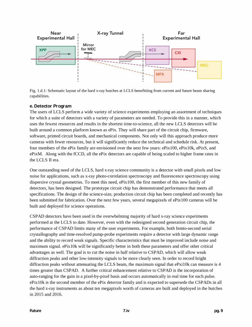
Fig. 1.d.1 below shows how the beam can be multiplexed once we have thin crystals in bothmonochromators and MFX on line. In this configuration, if there were two compatible mono experimentsin XPP and XCS, we could then use the mirror to quickly switch the remaining spectral components ofthe “pink beam” to MFX, CXI, and/or MEC.
Future 7.iv pg. 9
Fig. 1.d.1: Schematic layout of the hard x-ray hutches at LCLS benefitting from current and future beam sharingcapabilities.
e. Detector ProgramThe users of LCLS perform a wide variety of science experiments employing an assortment of techniquesfor which a suite of detectors with a variety of parameters are needed. To provide this in a manner, whichuses the fewest resources and results in the shortest time-to-science, all the new LCLS detectors will bebuilt around a common platform known as ePix. They will share part of the circuit chip, firmware,software, printed circuit boards, and mechanical components. Not only will this approach produce morecameras with fewer resources, but it will significantly reduce the technical and schedule risk. At present,four members of the ePix family are envisioned over the next few years: ePix100, ePix10k, ePixS, andePixM. Along with the fCCD, all the ePix detectors are capable of being scaled to higher frame rates inthe LCLS II era.
One outstanding need of the LCLS, hard x-ray science community is a detector with small pixels and lownoise for applications, such as x-ray photo-correlation spectroscopy and fluorescence spectroscopy usingdispersive crystal geometries. To meet this need, ePix100, the first member of this new family ofdetectors, has been designed. The prototype circuit chip has demonstrated performance that meets allspecifications. The design of the science-size, production circuit chip has been completed and recently hasbeen submitted for fabrication. Over the next few years, several megapixels of ePix100 cameras will bebuilt and deployed for science operations.
CSPAD detectors have been used in the overwhelming majority of hard x-ray science experimentsperformed at the LCLS to date. However, even with the redesigned second generation circuit chip, theperformance of CSPAD limits many of the user experiments. For example, both femto-second serialcrystallography and time-resolved pump-probe experiments require a detector with large dynamic rangeand the ability to record weak signals. Specific characteristics that must be improved include noise andmaximum signal. ePix10k will be significantly better in both these parameters and offer other criticaladvantages as well. The goal is to cut the noise in half relative to CSPAD, which will allow weakdiffraction peaks and other low-intensity signals to be more clearly seen. In order to record brightdiffraction peaks without attenuating the LCLS beam, the maximum signal that ePxi10k can measure is 4times greater than CSPAD. A further critical enhancement relative to CSPAD is the incorporation ofauto-ranging for the gain in a pixel-by-pixel basis and occurs automatically in real time for each pulse.ePix10k is the second member of the ePix detector family and is expected to supersede the CSPADs in allthe hard x-ray instruments as about ten megapixels worth of cameras are built and deployed in the hutchesin 2015 and 2016.

Future 7.iv pg. 10
Silicon drift detectors (SDDs) have been used in a few LCLS user experiments, but with mixed results atleast partially due to their very limited channel count, while at synchrotrons and in many other fieldsSDDs have proven to be a critical technology. ePixS, where the “S” is for spectroscopy is an adaptation ofePix100, that has larger pixels and lower noise. It will be capable of offering SSD-like energy resolution,but with hundreds to thousands of channels, essentially creating an SSD for FELs, where channel countand not count rate is the defining parameter. The cost per ePixS channel is expected to be 100 times lowerthan for SDDs.
LCLS has recently acquired a two-plane pnCCD system from the Max Planck Society, which has seenheavy use in four different hutches since its arrival in the fall of 2013. Given the supply of spare parts andthe historical rate of module damage, this camera is expected to be a mainstay of the LCLS soft x-rayprogram for two to three years before becoming non-functional. A pair of technologies is being pursuedas a replacement to the pnCCD and to complement its performance: ePixM and the fCCD from LBNL.ePixM is a monolithic CMOS sensor with a fully-depleted bulk, which is a technology first developed atStanford. ePixM will offer very low noise, very small pixels, and is expected to cost significantly less perpixel than detectors based on hybrid architectures or custom sensors. The second generation Fast CCDfrom LBNL has been used in one characterization experiment and one user experiment at the LCLS inearly 2014. Active discussions are underway to acquire a camera for dedicated use at LCLS and tocollaborate on future designs matched to the specific needs of the LCLS.
Pixel Pitch Chip Size(pixels)
FrameRate
Noise(r.m.s.)
MaximumSignal
Gains
CSPAD 110 m 185x194 120 Hz 1,100 eV 20 MeV 2ePix100 50 m 352x384 500 Hz 225 eV 800 keV 1ePix10k 100 m 176x192 1 kHz 650 eV 80 MeV 2 Auto RangingfCCD 30 1024x1024 120 Hz ~100 eV 200 keV
Table 1.e.1 Expected initial performance specifications of the existing detectors.
2D Electron/Ion DetectorOver the past two decades momentum resolving spectrometers have transformed electron and ionspectroscopy. Momentum spectroscopy has enabled a new class of experiments in both laser basedultrafast sciences, and x-ray spectroscopy. The fundamental concept of these spectrometers is that thearrival time and position of each fragment is measured. From this data the momentum vector of eachparticle can be calculated. Science examples requiring such a detector range from Coulomb explosionimaging of large molecules for supporting alignment information in diffractive imaging experiments totime-resolved photoelectron imaging of nanoscale targets. So far, there exists no suitable detectortechnology for this class of experiments with fourth generation light sources such as LCLS.

Future 7.iv pg. 11
Fig. 1.e.1: Basic detector design: The thin silicon sensor will be bump bonded to the ASIC readout logic.
We are developing a revolutionary detector for electron and ion spectroscopy based on silicontechnology. The concept of the new detector is that a charged particle impinging on the detector willcreate electron-hole pairs in a thin silicon sensor. The generated charges will be read out with high timingprecision. The basic detector design is shown in Fig. 1e.1. A thin silicon sensor will be bump bonded tofast read-out electronics based on an Application-Specific Integrated Circuit (ASIC). As the electronmobility in silicon is much higher than the hole mobility, the sensor will be designed so that the electronstravel through the sensor to the read-out electrode and the holes travel to the entrance electrode.
We have started designing a first prototype of the detector funded by the SLAC LDRD program. Theanticipated performance of the detector has a spatial resolution of 100 microns and a time resolution of afew hundred picoseconds. The prototype detector chip will have 48x48 pixels. The first prototype detectorshall have an array of 2x2 chips resulting more than 9000 particle detection channels. We anticipatehaving a first functional prototype in mid FY15. Test measurements and iterative improvements of thedetector chip are planned for FY15 and FY16. By the end of FY16 we will perform benchmarkexperiments showcasing the performance of the new detector with a science application. Upon successfuldemonstration of the new detector we are planning to apply for follow up funding and scale the system tolarger chip sizes. Further, we plan to concurrently deploy the new detector technology for LCLSexperiments were multi-hit capabilities are required.
f. Rapid Data AnalysisThe ability to rapidly process data is critical to the success of LCLS experiments and for the efficient useof beamtime. This is due to the various complexities associated with experiments at a free electron laser:x-ray pulse fluctuations, relatively small allocation of beamtime for each experiment, and samplemutation issues. Experimenters need the information obtained from data analysis to make an educateddecision on how to proceed with their experiment. The LCLS has developed two tools to accomplish thistask.
The first tool, the online Analysis and Monitoring Implementation (AMI), is a user-configurable, GUI-based analysis that does not require any user coding or preparation. The second tool is the interactivepsana (Photon Systems ANAlysis) software. The features of interactive psana include:
Support for both C++ and python;Command line interfaceAbility to capture commonly used algorithms in reusable “modules” that can be chained togetherin a serial fashion;Support for calibrating images using standard tools;

Future 7.iv pg. 12
A new Data Description Language (DDL) that allows automatic code generation for both C++and python data access;Ability to run the same software offline and online (with real-time plot display);Ability to analyze data parallelizing over events (up to thousands of cores).
The psana framework is becoming the main analysis framework for LCLS because of its uniqueadvantages: it is simple to use, free and open-source, able to use the same code for real-time monitoringand for offline analysis, and works both interactively and in batch mode. A few critical projects arerequired to make it widely adopted:
Increase the speed through local and Message Passing Interface (MPI) parallelizationIncrease the flexibility through XTC (online data file) indexingAdd the ability to display real-time plotsAdd more powerful algorithms driven by LCLS physics.User training by the instrument engineers in the use of ipsanAdoption of more general detector handling APIs with a reduced set of access functions
We will execute these projects in the next 2 years.

Future 7.iv pg. 13
2) New Beam Capabilities
In the following section we describe different beam modes that were developed over the last years. Thetechniques described here are in varying stages towards standard user operation and several LCLSscientists and users have started to employ these capabilities for their experimental programs. Activities tofully develop their operation will be conducted during MD times and priorities of those developments areset in the joint LCLS division meetings to reflect the scientific program identified by LCLS.
a. Multi-Color X-Ray Beam ModesDuring the past two years various methods were developed to deliver two color and two-bunch x-raybeams:
A method for SASE beams using two undulators is depicted in Fig. 2.a.1. Using this approach,the undulator system is split into two ‘independent’ systems that amplify the FEL pulses underslightly different conditions, thereby generating pulses with two different energies. It is possibleto tune the photon energy, pulse delay and pulse duration.A typical spectrum is shown in Fig. 2.a.2.The iSASE method interleaves the K values of alternating undulators (Fig. 2.a.3). It is therebypossible to generate a beam containing two distinct photon energies with zero delay with respectto each other.A dual photon energy pulse with adjustable delay can be generated using the double slotted foilwhich splits one electron beam pulse into two by spatially masking out a part of the electron pulseenergy spectrum in a high dispersive region. This method is illustrated in Fig.2.a. 4.A dual bunch can be generated using a double drive laser pulse at the photocathode that generatesthe FEL beam. This is accomplished using a pulse splitter/stacker as part of the drive lasersystem.
Multi-Color Schemes
Fig. 2.a.1: Generating dual pulses using undulators set to different K values. Color, pulse delay and duration aretunable.

Future 7.iv pg. 14
Fig. 2.a.2: Two-color beam on SXR spectrometer (18 fs pulse duration, 1.5 keV, 19 eV energy separation).
Fig. 2.a.3: Two-color generation using the iSASE method. Alternating K1 and K2, instead of simply detuning givesa Two-Color scheme instead of simple bandwidth reduction. For K1 = K2 it is the regular SASE. K1 K2 gives2,3,4 colors configurations, depending on the phase advance.
Fig. 2.a.4: Generating dual pulses using undulators set to different K values and slotted foil application. Color, pulsedelay and duration are tunable. The distance between slots controls the delay between pulses.

Future 7.iv pg. 15
Two color beam delivery using the HXRSS systemSome of these methods can be used in combination with HXRSS to deliver dual pulses which areseparated in time and/or energy. One particularly intriguing method is to take advantage of intersectingcrystallographic planes of the HXRSS diamond crystal that provides the opportunity to generate twoseeding energies by taking advantage of the relatively broad energy spectrum of SASE FEL beam that istransformed into the seed.
The hard x-ray self-seeding device was conceived to deliver a very narrow seeded spectrum using aparticular Bragg or Laue diffraction plane of a thin diamond crystal. The seeded photon energy iscontrolled by crystal pitch and the electron beam energy. Due to strong user interests in two-color FELoperation, the LCLS accelerator team used the crystal yaw angle to bring two diffraction planes within theSASE bandwidth (about 20 eV) at the photon energy 8.45 keV for simultaneous two-color seeding. Thecolor separation can be completely controlled by yaw angle alone without adjusting any other machineconfiguration (see figure below). The technique is scalable to any seeded photon energy ranging from 7.1keV to 9.5 keV.Fig. 2.a.5 illustrates the arrangement of the crystallographic planes of the diamond crystal, Fig. 2.a.6schematically displays the arrangement of the seeding crystal with respect to the FEL beam (left) andshows the dual energy pulses (right).
Fig. 2.a.5: Photon Energy as functions of diamond crystal yaw angle for accessible crystallographic planes.

Future 7.iv pg. 16
Fig. 2.a.6: Left: Orientation and rotational movements of the diamond crystal with respect to the FEL beam. Right:Dual photon energy pulse spectra for different crystal yaw angles.
Seeded Bunch FEL Operation for High-Intensity 2-Color X-RaysA recent development for the Hard X-ray Self Seeding beam program is the delivery of seeded 2 bunch –2 color X-rays (also for SASE operation). Two electron pulses are generated at the photocathode,accelerated and propagated through the undulator system and HXRSS systems. SASE or Seeded 2-colorpulses with adjustable delay have been achieved with peak power comparable to standard operation (thisis an improvement of 10 over other methods). This 2-color scheme enables new types of pump-probe andimaging experiments at hard x-rays! Typical energy separation of the two pulses is about 80 eV, withpulses of ~ 20 fs and 180 J per pulse. Figs. 2.a.7 and 2.a.8 show examples the seeded spectra. This newmode is currently transitioning to operations and we conducted a first successful user experiment.
Fig. 2.a.7: Spectrometer image of a seeded 2 – Bunch 2-Color x-Rays beam.

Future 7.iv pg. 17
Fig. 2.a.8: Integrated lineout of a seeded 2 – Bunch 2-Color x-Ray beam.
b. Soft X-Ray Self-SeedingThe goal of the SXRSS project was to design, construct, and test a FEL soft x-ray self-seeding device.Two institutions, SLAC and LBNL, contributed to the design, engineering, fabrication, and testing. Thedesign is similar to the HXRSS system. Instead of using a crystal, a ruled grating provides the capabilityof diffracting the incoming x-ray beam to select the seeding wavelength (Fig. 2.b.1). The design providesa wavelength range of 500 eV to 1 keV for seeding in the soft x-ray photon energy range with a designresolving power of 5000.
Fig. 2.b.1: Soft x-Ray Self seeding System (M1, M2, M3: X-Ray Mirrors, G: Grating, lower part illustrates thearrangement of the electron chicane bending magnets).

Future 7.iv pg. 18
Recently, the R&D phase of the project came to completion. Seeding at 860 eV has been demonstratedwith a relative bandwidth of less than 2x10⁻⁴. The optimization has been done at this photon energy. Inadditional seeding was observed across the design wavelength range (0.5-1keV).
Currently, work is performed to transition the SXRSS system to normal operation to prepare forupcoming user demands. The goal is to be able to provide seeded beams in the Soft x–ray range to userwith the beginning of the upcoming run 10 (October 2014). Main tasks are streamlining the operation ofthe system, optimization of seeding across the entire design energy range and increasing the peakbrightness at all energies. We expect to expand the energy range up to 1200 eV and possibly as low as300 eV. A part of the performance optimization is to develop effective undulator tapering strategies,which are also required to increase pulse energies towards the terawatt goal.
To aid all of these studies as well as the user program, a new shot-by-shot soft x-ray spectrometer is understudy. In the longer term (3-5 years), we are considering the possibility of two-color soft x-ray self-seeding, which will require additional hardware (for timeline see Table 2.b.1).
Time Project Phase
FY14 Transition to Operation
FY15 Expansion of energy range (300 eV - 1200 eV)
FY16-FY17 Development of two-color soft x-ray self-seeding
FY18 and beyond Adopt system to LCLS-II parameters
Table 2.b.1: Planned timeline of the Soft X-Ray Self Seeding program at LCLS
c. Soft X-Ray PolarizationA polarizing undulator (Delta undulator) and an up-beam phase shifter will be installed at the end of theLCLS undulator line in place of U33 and commissioned by the end of CY2014. The LCLS FEL producesintense x-ray radiation from a high energy electron beam with fixed, linear polarization. The addition willbe compact, similar to the existing LCLS undulator segments, but can be operated in one of three modesto either produce fully tunable polarized x-ray FEL beams, or boost fundamental or second harmoniclinearly polarized FEL output. Controlling the polarization state of FEL radiation has broad applicationsfor probing valence charge, spin, bonding dynamics, phonons and emergent phenomena on fundamentaltime and spatial scales. The 3.2-m-long Delta undulator is expected to produce polarized radiationintensities at the GW-level with degrees of circular polarization close to the 90% level at soft x-rayphoton energies up to about 1.5 keV. Fig. 2.c.1 shows performance estimates for the basic setup. Thedegree of polarization can be further enhanced by reverse tapering of the LCLS planar undulators and/orthrough collimation of the linear polarized light from the LCLS planar undulators. The system will beoperational from early FY15 until the decommissioning of the LCLS facility. With the phase shifter theDELTA undulator can be used to investigate the so-called cross-undulator configuration in order toprovide rapid polarization switch. Shot-by-shot polarization diagnostics will be developed and installed in

Future 7.iv pg. 19
the LCLS. The Delta undulator will later be used, together with up to 2 additional undulators of the sametype, as polarizers for the LCLS-II SXR beamline (for timeline see Table 2.b.2).
Time Project Phase
FY14 R&D Phase
FY15 Commissioning and Transition to Operations
FY16-FY18 Routine Operation
Table 2.b.2: Timeline of the planned Soft X-Ray Polarization program at LCLS.
Fig. 2.c.1: Estimated LCLS Delta Polarized Radiation Properties.
d. Electron Energy StabilityLCLS beam energy stability was previously found to be outside the acceptable limits for stable operationof seeded FEL operation. Following recent linac configuration changes and regular maintenance, theenergy stability is now found to meet or approach the requirements to stabilize self-seeded FEL intensityto the empirically nominal 20% RMS level. The maximum relative RMS energy jitter requirements arefound to be 2.5e-3 for HXRSS and ~5e-3 to 6e-3 for SXRSS. As shown in Fig. 2.c.2, RMS energy jitterfor hard x-ray operation has been reduced from >5e-3 to 2.4e-3, reducing the HXRSS power fluctuationsfrom >72% to 20%, as expected. The impact of energy jitter (< 7e-3) on the recently developed SXRSS isstill being evaluated.

Future 7.iv pg. 20
In the short term (3 months), efforts will be concentrated on ensuring regular delivery and verification ofthe optimized setup. This includes the deployment of newly developed linac jitter analysis tools foroperations to quickly identify maintenance issues, as well as modifying controls to allow the increasedflexibility required to regularly apply the new linac phasings used to further reduce jitter.
As the above corrections leave zero tolerance for general linac performance, hardware improvements arestill recommended in the long term (1-2 years), both to relax operational constraints and to furtherimprove general performance. Prior pulse forming network upgrades have shown mixed results and arebeing evaluated. High-level RF correction via fast feedback through LLRF modulation is beingalternatively considered.
Fig. 2.c.2: Two-dimensional histograms (top) of the LCLS seeded FEL pulse energy, less SASE contributions,versus relative beam energy with one-dimensional histograms (bottom) of relative beam energy. Plots shown forHXRSS at 8.3 keV in May 2012 (left) and April 2014 (right) demonstrating a factor of >2 reduction of energy jitter.
e. XTCAVAn X-band transverse deflecting cavity (XTCAV) was installed downstream of the LCLS undulatorbeamline and tested in early 2014 for user operation. This device measures the electron bunch time-energy phase space distribution. Since it is located after the undulator, time-resolved FEL lasing effects(electron energy loss and energy spread increase) can be measured. By comparing images between FEL-on and FEL-off conditions, we can reconstruct the X-ray temporal profile for each lasing shot withoutinterrupting FEL operation. A schematic depiction of the system is given in Fig. 2.e.1.

Future 7.iv pg. 21
Fig. 2.e.1: Diagnostics layout of the X-ray temporal measurement.
The deflector and camera can work at 120 Hz so each shot can be recorded. Presently the number ofpixels in the energy (vertical) direction is limited to < 350 pixels at this rate. This is acceptable for hardX-ray modes where the full vertical range is not required. For soft X-rays, to avoid image truncation, thefull ROI is preferred, but the camera must be acquired at 60Hz or less for beam-synchronous acquisition.The best temporal resolution measured is about 1 fs rms for soft X-rays (800 eV), and about 4 fs rms forhard X-rays (8 keV). As an example, the temporal profile reconstruction of soft X-ray pulses is illustratedin figure 2.e.2. The electron beam energy is 4.7 GeV with FEL operating at a resonant photon energy of1.0 keV. We first suppressed the lasing process by perturbing the electron horizontal trajectory at thebeginning of the undulator and then recorded hundreds of what we refer to as ‘lasing-off’ or ‘baseline’longitudinal phase space images on the screen. Panel a in figure 2.e.2 shows a typical single-shot baselineimage. Its projection onto time gives the electron bunch current profile. Next, we restored the electrontrajectory and recorded the ‘lasing-on’ images for normal operation (a single shot is shown in panel b).On comparing panel b with a in Fig. 2.e.2, one can clearly see the time-resolved energy loss and energyspread growth due to the lasing process.
Fig. 2.e.2: Temporal profile reconstruction. The electron bunch charge is 150 pC with an energy of 4.7 GeV toproduce photons at 1.0 keV. The measured single-shot longitudinal phase space images are shown in a: ‘lasing off’and b: ‘lasing on’. Comparing the ‘lasing-off’ with the ‘lasing-on’ images, we reconstruct the X-ray power profile asshown in c from the time-dependent energy loss (blue curve) and energy spread growth (red curve). The electroncurrent profile (green-dashed line) is also shown in c. The example shown here is measured just after saturation witha total X-ray pulse energy of 1.5 mJ. The bunch head is to the left in these plots and throughout.
To record XTCAV data from the user side, in each machine configuration, MCC needs to performcalibrations and also suppress lasing for the user to record baseline (non-lasing) images. A configurationfor the LCLS DAQ system is currently being finalized at which point more detailed documentation ondata acquisition procedure and analysis will also be posted. A detailed summary of the XTCAV system isdescribed in a recent publication by Behrens et al. in the journal Nature Communications.

Future 7.iv pg. 22
3) Efficiency
a. Linac Infrastructure Mission ReadinessThe Mission Readiness (MR) program was developed during the past year to address acceleratoroperational issues such as high maintenance cost, obsolescence, operational and safety risks. It focusseson SLAC’s infrastructure that serves the LCLS Accelerator and FEL. The high level goal is to ensure thatthe accelerator and associated infrastructure is capable to deliver the x-ray beam to the LCLS users and tooptimally enable the LCLS science program while ensuring maintenance of the accelerator can be doneefficiently. We anticipate completing the proposed plan within an 8-10 year time frame. Priorities wereestablished based on risk and anticipated Return of Investment. The ‘Return of Investment’ is defined asreduced operational cost of system and the prevention of future exponential cost growth typical for themaintenance of end of life systems. Added benefits are improved performance and new capabilities thatare typically associated with modern equipment.
To develop the Mission Readiness Program, the critical accelerator infrastructure has been evaluated toidentify high risk items. Each item has been assigned a number of risk levels in a variety of categories:program, cost, ES&H, technical and likelihood of failure. A relative ranking of all items was performedby combining all risk categories. Additional ranking was established by evaluating the Return ofInvestment.
Project Mitigated risk
FY14 FY15 FY16 FY17 FY18
Klystron Modulator Upgrade 1.8 3.0 Addresses maintainability and performance ofklystron modulators, future maintenanceprogram uses significantly less staff.
Beam Switch Yard PumpStation Replacement
1.8 1.7 Removes risk of unrepairable failures, reducesrequired staff for repairs and maintenance, andaddresses oil leaks into vacuum system.
PPS System Upgrades, I/Odevices and cables
0.9 3.0 0.1 Significant reduction of failure rate, reducedmaintenance staff, ensures compatibility withfuture LCLS expansion.
Linac LLRF System Phase 1 0.25 1.75 Replacement of obsolete, maintenanceintensive LLRF system with modernelectronics, reduces labor effort formaintenance and repair. Use of commercialequipment to replace mix of SLAC built andobsolete commercial hardware.
VMDD CNC Mill 0.32 Replacement of inoperable machine, supportof LCLS mission, reduced personnel effort tocarry out manufacturing program (benefitsmechanical and klystron support program)
HPRF Test Stands 0.3 0.1 2.1 0.5 Current high power RF test stands are at theend of life, appropriate repairs frequentlyimpossible due to unavailable obsolete

Future 7.iv pg. 23
hardware. Upgraded system allow automationof test procedures, thereby reducing requiredstaff for operation.
Brazing furnace rebuild 0.25 Preserves unique SLAC capability for brazinglarge structures
METS Pit Furnace 0.6 Replaces furnace chamber
Klystron Solenoid PowerSupplies
2.5 2.5 Mopdern implementation of power supply andcontrols distribution, eliminates single point offailure.
Klystron Modulator PFNUpgrade
2.5 1.7 Replacement of End of Life components.
Linac LLRF System Phase 2 1.2 2.1 1.5 Replacement of obsolete, maintenanceintensive LLRF system with modernelectronics, reduces labor effort formaintenance and repair. Use of commercialequipment to replace mix of SLAC built andobsolete commercial hardware.
PPS Relays and Interlooks 0.8 1 Significant reduction of failure rate, reducedmaintenance staff, ensures compatibility withfuture LCLS expansion.
BSY Cold Cathode Gauges 1 Replace existing obsolete hardware after pumpstations are upgraded.
BSY Fast Valves 1 Replacement of obsolete device.
Acc. Cooling Water System 3.0 Replacement of many decades old watercooling components that are corroding anddeteriorating.
Linac Control System Camacreplacement
2.3 Replacement of obsolete controls hardwarewith modern TCA standard equipment.
Totals 5.37 9.8 9.6 9.8 5.8
Table 3.a.1: Five Year Mission Readiness Plan to address high and medium risk items.
During the past year, we conducted a number of reviews of the proposed plan, both external and internal.Recommendations were implemented as appropriate. All projects were assigned a responsible engineer todevelop cost, detailed scope and schedule. We now begun to implement a number of these projects usingour well established Accelerator Improvement Project formalism.
The total budget to complete all identified projects is approximately M$ 55. In FY2014, we plan to spendabout M$ 5 to launch the highest ranking projects. During the following years, this effort will ramp up to

Future 7.iv pg. 24
~ M$10 (FY15-17) and subsequently ramp down annually until completion. Table 3.a.1 provides anoverview of our current plan for the next 5 years.
To fund this effort, priority decisions are being made both in the Accelerator and LCLS Directorate. Bothdirectorates are developing a strategy to reduce the core operational cost by implementing measures toimprove overall efficiencies. A significant fraction of realized saving will be made available to conductthe MR projects. No additional funding beyond the overall LCLS operational budget is available for thiswork. The MR Return of Investment will allow SLAC to fund strategic Research and Developmentactivities that are needed to ensure the success of future light source projects at SLAC.
b. Commonality of Controls/DAQThe LCLS Photon Controls and Data Systems (PCDS) department provides a common platform forcontrols, data acquisition, data format and data analysis across all LCLS instruments, with twoexceptions.
The first exception is the fragmentation of the Python scripts developed by the various instruments tointerface to the EPICS slow controls framework. Existing systems originated from a central code base buthave diverged over time, with many improvements in different areas that could have been better unifiedacross instruments. This is currently being addressed through an operational improvement project (OIP)to unify the various interactive Python tools, to prevent future duplication of effort when makingimprovements to such tools. The OIP is on track to complete this effort by the end of the summershutdown in FY14.
The second exception is the fragmentation of analysis tools (psana, pyana, Matlab, CASS, AMI) adoptedby the different experiments. LCLS has created a working group, composed of PCDS staff, beamlinescientists, and instrument engineers, to help guide the process of making the LCLS data analysis systemsmore user friendly. One of the key goals of this group is to identify the analysis tools that should besupported in the long term. The working group has proposed that the interactive psana (ipsana)framework become the main development focus of the LCLS data analysis team. Significant effort hasalready been devoted to expanding the capabilities of the interactive psana framework, up to the point thatthis tool is already capable of replacing CASS and much of AMI functionality. Two additional OIPs, oneto add indexing capability to the raw data files in order to increase data access speed, and one to addparallel processing capabilities in order to optimize CPU usage, will complete the effort of making ipsanathe main LCLS analysis tool by the end of FY14.
The DAQ system currently provides two user interfaces to manage data acquisition: a Python API,invoked by the Python command line, and a Graphical User Interface. The former is mainly used by XPP,XCS and MEC instruments, and the latter by AMO, SXR and CXI instruments. Both interfaces have theirrespective advantages and therefore both will continue to be supported by PCDS.
c. Prioritization Process, WBS StructureLCLS has created a process for identifying potential enhancements to LCLS capabilities. In particular theprocess consists of creating proposals for enhancement projects with defined scope, schedule, and budget;socializing and evaluating the proposals; approving enhancement projects and capturing them within theLCLS Work Breakdown Structure; and tracking the progress of these projects. All enhancements toLCLS capabilities take place within this process.

Future 7.iv pg. 25
Enhancement proposals are created by LCLS staff (beamline and laser scientists, instrument engineers,detector scientists, PCDS staff, etc.). These proposals are formally presented to LCLS department headsat the Joint Divisions Meeting, where they are discussed and prioritized. Approved projects are enteredinto the LCLS WBS with a charge number, a CAM and WBS manager, and a project leader, who isresponsible for the project. The CAM and the leader work together during the planning, implementation,and completion phases of the project.
d. Cross Training of StaffTechnical staff to reduce total size, improve capabilities, and broaden coverageControls and DAQ to help support experimentsLaser scientists to help support experimentsBeamline scientists to reduce dependence on specialized support staff
o Controls - install and control motors, user equipment, trouble shoot, etc.o Laser - setup and configure basic schemes, trouble shoot, etc.
Users to reduce dependence on LCLS staffo Train on basic controls interfaceo Analysiso Basic mech/vac

Future 7.iv pg. 26
4) Support Facilities
a. Laser
NEHThe core NEH laser systems are stable and require only routine maintenance and incremental upgradessuch as replacing older hardware, e.g. to improve timing jitter performance, and adding new or improveddiagnostics. The mid-IR OPA setup on the general use table has been very successful in reducing set-uptime and providing consistent output and diagnostics of the mid-IR source. Similar mobile, well-definedconfigurations will be developed for the optical THz source and for the <10 fs hollow fiber source.Further improvements in THz conversion efficiency by cryogenic cooling of LiNbO3 crystals is beingdeveloped in the RLL, and this will be engineered for deployment in the LCLS hutches.
FEHAn increasing number of experiments in CXI require higher pulse energy and changes in wavelengthusing OPAs. Currently each of these configurations must be set up from scratch and disassembled afterthe experiment. To increase operational efficiency, we will develop stable, mobile configurations (alongthe lines of the mid-IR setup) for a multipass amplifier and an OPA stage.
In MEC, a second phase of upgrade to the femtosecond laser system is planned for late FY14. The outputof the nanosecond laser system will be used to pump a large aperture Ti:sapphire crystal configured as anadditional amplifier for the existing femtosecond laser. This is expected to increase the compressed pulseenergy to >8 J in 40 fs, for >200 TW peak power. Such high energy beams are subject to beam qualitydegradation, and a commercial deformable mirror and wavefront sensor will be used to increase the Strehlratio of the focused beam on target. The nanosecond laser will still be able to be used to drive shocks intargets. To improve the energy stability and the beam profile, we propose to replace the flashlamppumped Nd:YLF front end with a diode-pumped amplifier chain. LCLS also will evaluate improvementsin the temporal shaping of the fiber seed to provide more flexibility and operational efficiency in settingthe temporal shape of the nanosecond pulses. Numerous improvements in the diagnostics and controls ofboth laser systems are planned or underway.
XCS and XPP have similar X-ray focusing and diagnostic capabilities. XPP is one of the two most over-subscribed hutches at LCLS, and there would be a considerable operational advantages to move some ofthe XPP experiments to XCS to avoid the beam-pipe changeover required to switch between XPP and theFEH hutches. The majority of XPP experiments use optical lasers, so a laser system is needed in XCS toenable this program of offloading XPP experiments. The XCS laser system would require the same basicperformance as the oscillator/regen system in CXI, but will need to fit into a smaller footprint due tospace constraints. Eventually it is anticipated that this system will be upgraded with a multipass amplifierand all of the wavelength conversion systems used in other hutches.
Finally the planned “hutch 4.5” MFX instrument is being designed with space reserved for an opticallaser system, but to date the requirements for this system are still being defined.
TimingThe existing optical timing distribution has been very successful in maintaining low jitter and drift for theoptical pulses delivered to the LCLS. There are some challenges maintaining the system without directinvolvement by collaborators at LBNL, and some components of the system have no readily availablespares. Furthermore there is no backup system to switch to in case of a catastrophic failure. To address

Future 7.iv pg. 27
these issues, the LCLS timing group has developed a timing distribution and synchronization systembased on RF distribution rather than fiber. This system is currently in use for the two LCLS photoinjectorlasers and is currently undergoing commissioning at MEC and XPP. It is being installed in parallel withthe LBNL fiber system for redundancy and cross-checking of timing drift. During FY14-15 this systemwill be installed in parallel at the rest of the LCLS hutches (CXI, AMO, SXR, XCS in that order). So farthe SLAC system has shown improved timing jitter (<50 fs RMS).
Optical Setup LaboratoryThe existing RLL is being repurposed as a cleanroom for the assembly of beamline components. Topartially replace the RLL, a new optical setup laboratory in B950 is nearly complete, and it will have theLCLS-standard oscillator/regen/multipass, identical to those used for hutch operations. This lab will servethe same purpose as as the RLL of providing laser light to test users’ samples and detectors prior tobeamtime. In addition the lab has been configured to allow further engineering and development of themid-IR source and the engineered version of the optically-pumped THz source. Additional laser lab spacein B750 is being refurbished to provide space for R&D efforts on optical sources, such as the cryo-cooledTHz source, <10 fs sources, short-pulse UV sources, HHG sources, etc.
b. Sample PreparationOur level of understanding of sample injectors is now advanced enough that we may communicate ourspecific needs to potential manufacturers. Standard etched microfluidic device construction, hardlithography, 3D printing and micro injection molding are all actively being pursued with the expectationof commercial availability by at least one of these methods in a 1 to 2 year time frame. Submicron dropaerosolizers can also be produced in-house for use in single particle imaging, SPI,experiments. However, if LCLS is to eventually be able to image single molecules, a new type of injectorthat produces even smaller droplets, under 100nm will be required.
A “FEL simulator” station consisting of an optical laser and hit rate counter, will be added to the ICL bysummer 2015 for off-line testing of liquid jets and gas phase injection. In order for users to gainexperience with the same sample delivery system as is used at the beamlines, a second sample deliverysystem will be installed in the ICL in the near term. Scheduled remote access will allow users to operatethe ICL sample delivery system from their home institutions.
In addition to the ICL, the Sample Characterization Lab, SCL, will also assist users with off-linepreparation. The SCL is still in the planning phase. The location, general layout and equipment needshave been agreed upon; architectural drawings will be the next step. When completed, the SCL willhouse the equipment necessary to characterize a sample and evaluate that sample’s potential to provideuseful data at the FEL.The Soft X-ray Department, SXD, and the in-air station hutch 4.5, will present the highest demand fornew sample delivery equipment in the near to mid-term and FEL upgrades and expansions will continuethat demand in the long term. As an example, all six endstations presently need some type of liquid targetinjector; three have similar or shared LCLS equipment available, MEC is pursuing one throughcollaboration, SXR has one available through collaboration with an outside group, and AMO does not yethave any liquid injector. We will gain efficiency by bringing equipment in-house and integrating it with astandard set of hardware and controls for similar tasks. LCLS II will bring new challenges for sampledelivery -high speed pulsed injectors will be desired to match the high X-ray rep rate. This is currently indevelopment as a collaboration with Stanford University.
Pulsed sample delivery will also be the enabling step for some types of experiments to be runremotely. Pulsed sources will use far less sample and will allow users to screen very many submicroliter

Future 7.iv pg. 28
sample volumes to find optimal conditions for extended runs to collect full data sets. Both screening andregular beamtime may then require little on-site handling and could possibly be run remotely from theuser’s home institution. A similar remote mode of operation is employed at synchrotron proteincrystallography beamlines and eventually will be the norm for most structural protein crystallographyruns at LCLS.
c. X-ray Optics Metrology LaboratoryLCLS requirse state of the art optics to deliver a variety of photon beam capabilities while preserving thecharacteristic properties of the XFEL. In order to realize the necessary upgrades to the existing opticsystems as well as develop the instrumentation capabilities for the LCLS-II source, LCLS will build anoptical metrology lab in the clean room facilities currently under construction in the NEH. The lab willstart with the basic instrumentation to properly characterize and install the upgrade of the Hard X-RayOffset Mirrors (HOMS) and eventually contain the full suite of tools to measure across the full PSD.
d. Other LaboratoriesSample prep/wet lab in 757FEH mezzanine sample prep/wet labSet - up space in FEH
Controls Training LabIn order to increase the capabilities and independence of users, LCLS will build an offline controlstraining center. The center will contain a full control system infrastructure and hutch interface that willprovide users the opportunity to familiarize themselves with controls and DAQ interfaces as well as setupand operate common functions.
CleanroomIn order to develop and support the broad suite instrumentation at the LCLS, large clean assembly spacewith a range of specification is required.

Future 7.iv pg. 29
5) Science InitiativesThe MFX instrument described in section in Section 1 is the result of a collaborative science initiativethat was created at SLAC with the formation of the Bio-Imaging Working Group headed by SoichiWakatsuki. Besides members from LCLS, the Bio-Imaging Working Group includes members from theStructural Molecular Biology (SMB) Division at SSRL, the SLAC Photon Science Directorate andStanford University. In the following we list two other science initiatives that will result in newinstrumentation and/or science programs at LCLS.
a. Roadmap to Single Particle ImagingSince its inception, the LCLS has been recognized as an x-ray source with the potential to supporttransformative techniques for structure determination. The goal of imaging single particles has long beenheld as one of the most important such advances. To date, a number of impressive studies have beenconducted and LCLS now seeks to accelerate the process of refining this technique and supporting itsroutine application by a broad user community interested in applications ranging from materials scienceto biology.
In March 2014, the LCLS and SLAC hosted a workshop that brought a wide cross-section of the usercommunity together with local experts to determine a suitable path toward the fulfillment of this goal.With the support of the LCLS user community, the facility will pursue a program of open-access,precompetitive aimed at the development of instrumentation, algorithms, and software that will enableadvanced imaging experiments to occur more rapidly and reliably.
We anticipate that this program will last between three and five years, meeting technical milestones thatwill be selected in conjunction with input from the user community to support key user science cases.The program will begin during the LCLS’s 10th user experiment run with input from the user communityprovided during the 2014 LCLS Users’ Meeting.
b. Matter under Extreme Conditions and High Energy Density ScienceThe Matter under Extreme Conditions (MEC) Instrument receives funding from both Fusion EnergySciences and Basic Energy Sciences. The MEC short pulse laser system is undergoing an upgrade from 4to 25 TW in phase 1 and then to 200 TW in phase 2. At these higher pulse energies, investigations of highintensity laser-matter interactions will become feasible. This project includes the construction of threemultipass amplifiers and cross-polarized wave generation (XPW) as well as the procurement of a newpump laser and deformable mirror. In addition, radiation safety activities are required because the lasersystem will be able to generate high energy electrons and x-rays. A radiation interlock system willexclude personnel from the hutch when high intensity laser beams are present in the target chamber. Inaddition, there will be measurements of the radiation inside and outside the MEC hutch first at 1019 andthen at 1020 W/cm2. In the present status, the phase one upgrade has been constructed and is now undercommissioning.
A formal program for optical-laser-only beamtime has started. An announcement was made at the SLACHigh Power Laser Workshop, October 1 and 2, 2013. After the first call for proposals, 6 proposals werereceived. The proposals are reviewed by a subset of the MEC proposal review panel (PRP). During theLCLS accelerator shutdown from early August to mid-October, 2014, three optical-laser-only beamtimeswill take place. It is anticipated that there will be a call for optical-laser-only proposals once a year. Theoptical-laser-only experiments will occur during each LCLS accelerator shutdown and potentially during

Future 7.iv pg. 30
the LCLS runs. This program will be especially valuable during the extended shutdowns necessary forLCLS-II installation.
The highest pressure achievable at MEC is limited by the pulse energies provided by the nanosecond lasersystem. These drive laser pulses result in a pressure of about 1.5 Mbar. In principle, the optical beams canbe focused tightly, but members of the MEC PRP have been skeptical about whether the shocks underthese conditions are sufficiently uniform. A project will be initiated to characterize and improve thenanosecond laser foci and the uniformity of the shock waves generated by these laser beams.Measurements will be made of the wavefront errors in the nanosecond laser beams, and corrections madeto the optical wavefronts. In addition, Velocity Interferometer System for Any Reflector (VISAR)observations will be made of the shock waves produced by the different drive laser conditions.
Phase contrast imaging has the potential to provide sub-micron resolution imaging of materials underdynamic compression. In collaboration with the University of Dresden, an optimized phase contrastimaging setup will be constructed. The MEC department is contributing engineering effort as well asprocuring a detector for this project. For two years, this new assembly for phase contrast imaging willstay at MEC instrument. After that, the components paid for by the University of Dresden will be shippedto the European X-FEL. Replacement components will then be fabricated for the MEC Instrument.
While the 200 TW upgrade to the MEC short pulse laser is currently underway, the MEC sciencecommunity has already begun a push for even higher peak intensities. This idea was presented andreceived strong support at the High Power Laser workshop at the 2013 LCLS Users Meeting. As a result,a White Paper was developed and presented to FES that discussed the scientific possibilities and some ofthe possible scenarios for getting PW peak power laser pulses and the LCLS X-ray pulses onto the sametarget. Because PW lasers are large and capable of generating significant amounts of hazardous radiationwhen interacting with a target, the two biggest issues to resolve when considering the PW upgrade are:where is there space for the laser and how can people be shielded from the radiation hazard. There arenumerous possible solutions to these two problems, but all require either new or modified conventionalfacilities. LCLS is currently planning an engineering study to better determine the cost and scheduleimplications of the various possible solutions during FY15. Further workshops will also be held to betterdefine the scope of such a project, including a determination of which type of PW laser system, highenergy (>250 J, <250 fs) or short pulse (>40J, <40fs), would provide the greatest scientific reach.

Future 7.iv pg. 31
6) Roadmap to LCLS-II OperationsThe LCLS-II project will include a new superconducting (SC) linac capable of producing intense electronpulses at up to 1 MHz repetition rate and energies up to 4 GeV. This SC linac will feed a variable gap softX-ray undulator producing high-rep-rate X-ray pulses in the 0.2-1.2 keV range. Also included in theproject is a new variable gap tender/hard X-ray undulator that will replace the existing LCLS undulator.When driven by the SC linac, it will serve an energy range of 1-5 keV at high rep rate, and when drivenby our existing 120 Hz Cu linac it can reach photon energies up to ~25 keV.
The six LCLS instruments will undergo modifications and enhancements to operate with the enhancedbeam properties delivered by the LCLS-II project. The definition and execution of the changes to theLCLS scientific instruments will follow a three step process:
1. Definition of the instrumentation needs2. Conducting strategic research and development activities to enable the technologies for
instrumentation3. Construction and implementation of enhanced instrumentation
The following sections outline the tactics associates with these steps.
a. Definition of the Instrumentation Needs for LCLS-II OperationsLCLS-II will expand the scientific capabilities of the LCLS facility with higher repetitions rates andincreased photon energy. This will both better serve the current scientific community and engage newusers at LCLS. Alignment between the community’s needs and the facility’s instrumentation is criticalfor enabling the best science. This alignment requires dialogue. A weeklong series of workshops willtake place September 22-26, 2014 to introduce the possibilities of LCLS-II to the scientific communityand define instrumentation development priorities.
Each daylong workshop will be co-organized by members of specific scientific communities and anassociated LCLS staff scientist. The workshops include:
Dynamics of atomic and molecular systems excited by both optical and x-ray radiation.Chemical dynamics and reactivity on surfaces and in solution phase systems.Dynamics of electronic structure of materials with element specificity and spin and orbitalsensitivityHigh energy x-rays for probing bulk materials and short range structureBiology using both scattering and spectroscopic probes to study the structure of biologicalsystemsNon-linear interactions of x-rays with matter enabled by ultrahigh intensity x-ray pulses fromLCLS-II
b. Strategic R&D in Support of LCLS-II OperationsWe have identified four areas of strategic R&D in support of LCLS-II operations: x-raydetectors, x-ray data systems, optical lasers and superconducting undulator technology. Thespecific details of these R&D initiatives will be honed following the LCLS-II instrumentationworkshops. Nevertheless, generic tactics of these areas can be formulated. The followinginitiatives will be conducted over the next 3 years:

Future 7.iv pg. 32
X-ray detector developmentsThe properties of the new LCLS-II source, in particular the high repetition rate (up to 1 MHz) andextended photon energy range (250 eV - 25 keV), will provide a means to address important scientificquestions in a broad range of disciplines. Experimenters will use various x-ray scattering andspectroscopic techniques and this in turn will drive a wide range of detector requirements. When onecompounds to this fact the need to span two orders of magnitude in photon energy, it becomes evidentthat a suite of detectors is needed. The following goals will serve as the criteria driving the developmentof this detector suite:
Meet the specifications defined by the scientific needsMinimize development costs of the detector suiteMinimize the resources and costs to operate and maintain the detector suite to ensure asustainable operations model
We envision the suite to include two ‘flavors’ of detectors (spectroscopy, imaging) for each of threephoton energy regimes [soft (250–1250 eV), tender/hard (1–15 keV) and very hard (15-25 keV)]. Thisleads to a total of 6 tailored detector systems.
Spectroscopic detectors:The key characteristics of spectroscopic detectors is very low-noise performance, good quantumefficiency and high spatial resolution. X-ray spectrometers are typically operative in a dispersivegeometry, mapping photon energy onto a spatial dimension. For this reason, there is a coupling of thedetector spatial resolution and the achieved energy resolution. In addition, the detected x-ray patterns areweak and detecting single photons that may be shared across multiple pixels is crucial. Theserequirements are particularly challenging in the soft x-ray regime.
Imaging detectorsIn contrast to spectroscopic detectors, imaging detectors are intended to resolve patterns with a widerange of intensity distribution, which can include very intense and very weak Bragg peaks. This class ofdetectors is characterized by large pixel well depths, modest spatial resolution and low noise. Imagingdetectors are large in size, i.e. many megapixels, to sample a large range of reciprocal space.
All of the abovementioned detectors can operate in two modes: ‘accumulating’ and ‘pulse-by-pulse’. Inthe first category the experimental parameters do not change over the accumulation time that is longcompared to the pulse-to-pulse time. These include: timing jitter between pump and probe, sample state,FEL intensity, etc. Therefore detectors sought to work in ‘accumulating’ mode can be read out at a speedslower than the machine repetition rate but have to provide stable performance over the accumulationtime and large dynamic range. In the second category the experimental parameters change on a pulse-by-pulse basis requiring detectors with a readout speed matched to the machine repetition rate and fastfeedback from beam diagnostic for data sorting and binning. These detectors should implement thepossibility to work on ‘Region of Interest’ (ROI) mode as well as triggering and veto mechanisms.
In order to minimize development costs and ensure efficient operations of the detector suite, a modularapproach will be used to maximize the commonality between systems. The detector systems will bedivided into 3 sub-components: sensor and front-end electronics, readout electronics, andcommunications firmware. We will develop a common framework that standardizes the readout

Future 7.iv pg. 33
electronics and communications firmware. This approach will minimize development costs and ensureefficiency in the integration and operation. The sensors and front-end electronics will be tailored for eachapplication. In some cases, different technologies will be explored. For example, CCD and CMOStechnology for soft x-rays, hybrid pixel arrays for tender/hard x-rays and high-Z material based hybridpixel arrays for very hard x-rays.
Partner laboratories will be pursued for the development of various sensors and front-end electronics.These partnerships will be explored and defined over the next 18 months.
X-ray data systemsThe high repetition rate (1-MHz) and, above all, the potentially very high data throughput (100GB/s)generated by LCLS-II requires sophisticated data acquisition and storage system and increased dataprocessing and data management capabilities. The main challenge will be developing high density, high-throughput, peta-scale storage systems that allow concurrent access from thousands of user submittedjobs. Additional critical capabilities include the deployment of a trigger/veto system, upgrading the SLACnetwork connection to the DOE Energy Sciences Network (ESNet), and expanding bandwidth andcapacity of the long-term tape archive.
Data AcquisitionTwo main modifications to the current system will be required for operating at high repetition rates:moving the event builder from online to offline and adding the ability to aggregate contributions frommultiple events in the readout nodes. These changes are required for running at 1-kHz or above,independent of throughput. Changes necessitated by increase in data throughput are: network linkupgrades (from 10Gb Ethernet to Infiniband or to 40Gb Ethernet) and online cache upgrades. Bothchanges are discussed later in the storage and network sections.
The deployment of a trigger/veto system for LCLS-II may be required. While the benefit of vetoingevents based on the event data is potentially very large (factors 10-100 are common for single particleimaging and nanocrystallography experiments), it will be challenging to implement an effectivetrigger/veto system. Vetoing based on beam parameters is not effective, as most x-ray pulses are of goodquality. Setting veto parameters based on the event quality for a given experiment is difficult becauseusers themselves often do not know which online feedback parameters might determine event quality, andare very suspicious of anything that could filter their data on-the-fly. In addition, a veto system is uselessfor experiments with hit rates close to 100%, which may very well represent the majority of future LCLS-II experiments.
Data StorageThe primary limitation for high-throughput experiments at LCLS-II will be storage technology: theexisting technology is too slow, and even a simple analysis task for one experiment would take weeks tocomplete. Spindle-based systems will become cheaper and denser, but not much faster or easier tomanage. Solid state systems will also become cheaper, but the current trend for commercial systems is tooptimize IOPS instead throughput and scalability, which are the two key aspects for a system hostingLCLS-II science data. In addition, current commercial systems come with a significant premium on thecost of the flash memory, making a multi-petabyte system prohibitively expensive. The SLAC tapesystem is approaching its limits in both overall storage capacity (~20+PB) and throughput. We are already

Future 7.iv pg. 34
seeing limitations when handling data from ongoing experiments and concurrent users’ requests to restorefiles from tape.
Data NetworkThe secondary limitation is network technology. LCLS would greatly benefit from having a 100Gbpsconnection between SLAC and ESNet. The primary usage for such a link would be the ability to offloadpart of the LCLS science data processing to some of the large DOE computing centers. For example,current LCLS data acquisition rates are up to 5 times the 10Gb link between SLAC and the NationalEnergy Research Scientific Computing Center at LBL (NERSC). It would take weeks before users areable to analyze, at NERSC, data they acquired at LCLS. With regard to the local network, Infinibandwould be superior to Ethernet for building a high throughput network for LCLS-II, especially under highcongestion conditions, but Infiniband has limitations due to its short maximum distance and its cost. It ismore expensive than Ethernet to connect devices that are not within 10m of each other, and significantlymore expensive to connect devices that are separated by more than 300m.
Data ManagementLCLS has developed a powerful data management system that handles both the automatic workflows ofthe data from the online cache to the various storage layers, and the users’ requests (e.g. restoring datafrom tape) through a web portal. Some aspects of the current system, such as checksum calculations,HPSS interface, and lack of prioritization, will become bottlenecked at higher data volumes and will needto be upgraded.
Data ProcessingThe increase of data processing capabilities doesn't present any particular challenge on the hardware side,even when considering the deployment of hybrid processing solutions (e.g. GPUs). The addition ofparallel capabilities to the analysis frameworks is already being developed for LCLS-I.
Data FormatLCLS DAQ is currently writing the raw data as XTC and users can request that their data be translated toHDF5. The translation step will become bottlenecked in the future and LCLS-II should target only onedata format for standardization. HDF5 is becoming the de-facto standard for storing science data at lightsource facilities, but, in order to effectively replace XTC in LCLS, a couple of critical format features arerequired. These features, namely the ability to read while writing and the ability to consolidate multiplewriters into a consistent virtual data set are currently missing in HDF5, however, the HDF group claimsthat these features could be added, given enough development resources.
SummaryThis is a summary of the critical projects required to build a data system able to handle the LCLS-IIrequirements:
1. Move the event builder from the online to the offline and introduce the ability to aggregatecontributions from multiple events in the readout nodes. Both changes are software-only, areincremental from what is currently in operation, and are required for running at 1kHz or above,independently of throughput. The online monitoring framework (AMI) and the offline framework(psana) will need to be adapted to the new paradigm.
2. Develop a custom, solid state, online cache (DAQ recorders) and offline storage (users dataanalysis) to solve the storage challenge. No vendor is currently offering high density, petascale,

Future 7.iv pg. 35
solid state storage solutions. SLAC has previously worked on peta scale flash-based systems andwe believe it's possible to build scalable, peta scale, solid state storage by aggregatingcommercial off-the-shelf components. This project presents medium risk with significant R&Dand development effort. The same technology could be used to build custom recorders for boththe online cache and the fast feedback system. The prototype of this project would be aninexpensive, high density (>100TB per rack unit), fast (10GB/s per 100TB), flash-based storagechassis.
3. Upgrade the LCLS local area network. The current system uses 10Gb Ethernet from the readoutnodes to the online cache and Infiniband (IB) from the online cache to the offline and within theoffline system. Introducing IB or 40Gb Ethernet from the readout nodes to the online cachewould be investigated. The final solution will be based on actual space constraints.
4. Add data management capabilities at high throughput. This includes upgrading the tape system,since we already see limitations when handling data from ongoing experiments and concurrentuser requests to restore files from tape. The data management framework should also beupgraded, because the current checksum calculations, HPSS interface and lack of prioritizationare destined to become bottlenecked at higher data volumes.
5. Increase data processing capabilities. This includes improving the parallel capabilities of theanalysis frameworks, introducing a different mechanism for generating HDF5 files, anddeploying a hybrid processing solution (e.g. GPUs or many-core solutions).
6. Develop a new timing system. The existing EVG/EVR system was not designed for MHzoperations and a new system will be required. Competency exists for this effort at SLAC and dueto the flexibility required over time, especially on the experiment side, this system should beprovided by SLAC, ideally through an RED/ICD collaboration.
7. Investigate a veto system. A veto signal could be delivered to the front-end electronics (EuXFELapproach), to the readout nodes, to the online cache or in the fast feedback layer. In general, aveto in the front-end electronics reduces the throughput requirements on the DAQ components,while a veto in the deeper layers provides cheaper/larger buffers and more time to reach adecision.
8. Investigate replacing POSIX-compliant file systems (currently Lustre and Gluster). This requiresexploring easier to maintain, easier to scale up, faster technologies. Big Data industry has beenmoving to distributed storage models. Large particle physics experiments have moved toXROOTD but that may not be the right solution for LCLS, because of the lack of strong securityfeatures and the inability to operate with HDF5.
The following projects were implemented by partnerships between SLAC and other institutions:
1. HDF5 upgrade: Some critical features are missing from the HDF5 API. The HDF group believesthese features are useful in general, not just for LCLS, and that they could, and should, be addedto the API. The group needs additional resources to work on these features.
2. Offline computing: Data centers built towards data intensive systems could help offload theLCLS/SLAC offline computing system. General support for LCLS offline analysis would require,at a minimum, ~50 PB tape storage, a dedicated ~10 PB of disk storage and ~100 teraflopprocessing farm with an aggregate throughput to the storage above 10 GB/s per PB. Other keyrequirements would be the ability for LCLS users to manage their data through the LCLS toolsand workflows, and the ability to use their SLAC account (or a federated account).
3. ESNet link upgrade: The ability to offload computing capabilities assumes an upgrade to a faster100Gbps connection between SLAC and ESNet.

Future 7.iv pg. 36
Optical Laser SystemsSignificant needs for laser R&D will be driven by the requirements of LCLS-II, principally thedevelopment of MHz, kW-class ultrafast lasers for pump-probe experiments and relativistic beamconditioning. Such laser sources would have immediate application in laboratory-based experiments inmaterial and chemical science, and enable technology for other areas of DOE mission interests such asaccelerator stewardship. Furthermore, kW-class lasers would drive fundamental and applied researchrelevant to the Stanford faculty, in areas such as the production of unique micro- and nano-structuredmaterials, high precision metrology, and XUV photonics, enabling SLAC to expand its scope of scientificresearch through new and strengthened collaboration with campus groups.
The existing LCLS has required significant laser engineering to maintain its high level of uptime andreliability, expert scientific support of complex experiments, and innovative development efforts toprovide unique wavelengths and delivery systems. LCLS-II will require these same capabilities alongwith the considerably challenging requirement of operation at high repetition rate, up to 1MHz for thephotoinjector and 100kHz to 1MHz for the experimental beamlines. To fully realize the potential ofLCLS- II, significant R&D will be required to develop appropriate laser sources. The two initial laserdevelopment objectives for LCLS-II are for the photoinjector lasers systems and for pump-probeexperimental laser systems.
The key features of the photoinejctor laser will be 1 MHz rep-rate with variable rep-rate capability, >50Waverage power in the IR to produce >5 W in the UV, with a flat top spatial profile, flat top temporalprofiles with varying duration over 10s of picseconds, and variable timing of individual pulses for beamspreader, >98% uptime. No commercially available lasers exist that can meet all of the requirements ofthe LCLS-II photoinjector, and the LS&T group will either develop an appropriate system at SLAC orwork with a commercial laser company to develop lasers systems to our specifications. Operating at 1MHz with ~50 J pulse energy, this laser system also would have immediate applications inphotoemission spectroscopy applications in chemical and material science as well as applications forSSRL pump/probe experiments.
The majority of experiments at LCLS involve a millijoule level pump/probe laser. While mostexperiments do not need such high energy pulses directly on sample, many do require nonlinearconversion to wavelengths that cover the range from VUV through THz. These conversion processes areinherently inefficient and require mJ level pulses to generate nJ to J level pulses at the sample asrequired by most experiments. To achieve comparable capabilities to realize the full potential of LCLS-II,R&D is required to develop lasers capable of providing mJ level, 10 fs pulses at up to 100 kHz forpump/probe experiments. Similar efforts are underway at DESY for pump/probe lasers for FLASH-II andthe European XFEL, and we will leverage these developments in our efforts for LCLS-II.
A 100 kHz, kW-class laser with fs laser pulses represents a two orders-of-magnitude increase in theaverage power of existing commercial ultrafast laser systems. Such a laser would become a key asset forSLAC, both for conducting further R&D for LCLS-II, e.g. through the development of wavelengthextensions (UV, THz, mid-IR, etc.) for this system, and by enabling numerous other research programs inPSD, AD, and other programs on Stanford campus. Just as with the conventional ultrafast lasers used inLCLS, access to this new high-rep-rate kW laser will benefit users and beamline scientists by enablingthem to test samples, detectors, and optical techniques in preparation for LCLS-II beamtimes.

Future 7.iv pg. 37
Superconducting Undulator TechnologyUndulators serve as the primary source of radiation for modern storage rings (SR) and Free-ElectronLaser (FEL) light sources. The advent of permanent magnet undulators (PMU) in the early 1980’sushered in an era of 3rd generation light sources, and since then improvements in undulator technologyhave served to continually enhance the flux and brightness provided to experiments by SR and FELbeamlines. A comparison of different undulator technologies clearly shows superconducting undulator(SCU) technologies, with much higher magnetic fields, as the leading candidates for future FEL-based x-ray sources (see Fig. 6.b.3).
In addition, SCUs have no permanent magnet material, and therefore are orders of magnitude lesssensitive to radiation dose, which is a serious risk for PMUs using a high-power electron beam. Inaddition, with the very high peak fields available, SCUs will offer more compact and more efficient FELdesigns in the future, clearly surpassing cryogenic permanent magnet undulators (CPMUs) and in-vacuumdevices with similar beam stay-clear dimensions.
This project is in collaboration with SLAC, ANL, and LBNL, and will demonstrate the viability ofsuperconducting undulator (SCU) technology for FELs, by building, measuring, testing, and correctingtwo 1.5-m long prototype SCU’s using two different technologies. The first technology is based onconductors of NbTi, the chosen technology at ANL, and the second is Nb3Sn, the choice at LBNL. TheNb3Sn conductor holds promise for the highest fields, but high-temperature processing of the conductoradds some technical risk. We will conduct independent cryogenic tests on each of the two undulatorsusing the same 2-m long cryostat, designed and built at ANL and based on an article installed at the APS,verifying the magnetic performance of each undulator using the same cryostat and magnet measurementbench. The FEL-specific undulator parameters, such as the magnetic field strength for the chosen periodand gap, and the magnetic field quality, field integrals, and FEL phasing over the undulator, must bedemonstrated.
Fig. 6.b.3: Peak magnetic fields vs. undulator period length for four different technologies (blue-solid: PM-NdFeB,cyan-dotted: PM-NdFeB-in-vacuum, green-dashed: SCU-NbTi, red-dash-dotted: SCU-Nb3Sn). All have the same5.7-mm vacuum chamber gap for comparison and a 7.5-mm magnetic gap, except the “in-vacuum” gap at 5.7 mm.

Future 7.iv pg. 38
A magnetic tuning technique will be developed and applied to each undulator as needed. The projectdesign and execution will rely heavily on already well-established designs of the undulator cryostat,undulator magnet core, and magnetic measurement systems developed and implemented for shorterundulators at the APS. It will also employ a unique magnetic tuning approach developed at LBNL. TheAPS SCU magnetic measurement system incorporates Hall-probe and rotating coils sensors modified forthe smaller vacuum pipe diameter; the system will furthermore incorporate a pulsed-wire techniquedeveloped at LBNL. The project deliverable, in 1.5 years (i.e., July 2015) from project start, will be twofully functional superconducting undulators that meet LCLS-II Hard X-Ray FEL undulator specificationsand demonstrate this enabling technology for long-term use in future light source projects, and possibly asa replacement for the LCLS-II PMU baseline design, if time allows. Prototype undulator parameters arelisted in Table 1, showing the slightly different period for each technology, based on the LCLS-II FELparameters.
Parameter Symbol NbTi Nb3Sn Unit
Undulator magnetic full gap gm 8.0 mmVacuum chamber full gap (internal) gvc 5.7 mmPrototype undulator segment length Lseg 1.5 mUndulator period u 21 19 mmPeak magnetic field Bmax 1.7 1.9 T
Table 6.b.1: SCU prototype parameters for each technology.
c. Construction and Implementation of Instrumentation in Support of LCLS-II Operations
The LCLS instrumentation suite will undergo enhancements to make optimal use of the new sourcesrealized with the LCLS-II project. The specific details of these enhancements will be defined in the seriesof workshops described above. However, generic needs in the following areas are identified already:
X-ray optics and safety systems: enhanced to handle high average power.Optical lasers: high repetition rate systems.X-ray detectors: high repetition rate and accumulating systems.Data systems: increased throughput to accommodate high repetition rate detectors.Controls systems: updated triggering system for high repetition rate operation.
As detailed previously, some of these areas require research and development before construction andimplementation of the respective instrumentation can occur. The activities should conclude in the 2-3 yeartime frame. Subsequent to this, LCLS will pursue an aggressive implementation of these technologies.This implementation is planned for the FY16-FY20 time frame as shown in Table 6.c.1.

Future 7.iv pg. 39
Table 6.c.1: Implementation plan for improvement programs for LCLS-II operations.