Strain-Based Deisgn Model for FRP-Confined Concrete Columns...
18
1011 SP-230—57 Strain-Based Design Model for FRP-Confined Concrete Columns by N. Saenz and C.P. Pantelides Synopsis: Synopsis: Synopsis: Synopsis: Synopsis: A constitutive strain-based confinement model is developed herein for circular concrete columns confined with fiber reinforced polymer (FRP) composites. A series of relationships were developed from experimental data, which facilitated the establishment of the strain-based model. The FRP-confined concrete constitutive model calculates the internal damage of the column by using the radial strain. The radial and axial strains at zero volumetric strain were used to mark the beginning of effective dilation response of the FRP composite jacket. The secant concrete modulus was used in the model and expressed as a function of the secant modulus softening rate, which depends on the ultimate radial to axial strain ratio. The experimental relationship for the ultimate radial to axial strain ratio is a function of the normalized effective confining stiffness. The secant modulus softening rate is constant throughout the plastic stress-strain response until failure. The FRP-confined concrete constitutive model evaluates the ultimate radial strain, which was related to the FRP composite effectiveness. The FRP-confined concrete model predicts the stress-strain response accurately for any normalized effective confinement stiffness. Keywords: confinement; constitutive model; stress-strain relationships
Transcript of Strain-Based Deisgn Model for FRP-Confined Concrete Columns...
1011
SP-230—57
Strain-Based Design Model forFRP-Confined Concrete Columns
by N. Saenz and C.P. Pantelides
Synopsis:Synopsis:Synopsis:Synopsis:Synopsis: A constitutive strain-based confinement model is developed herein forcircular concrete columns confined with fiber reinforced polymer (FRP) composites. Aseries of relationships were developed from experimental data, which facilitated theestablishment of the strain-based model. The FRP-confined concrete constitutivemodel calculates the internal damage of the column by using the radial strain. Theradial and axial strains at zero volumetric strain were used to mark the beginning ofeffective dilation response of the FRP composite jacket. The secant concrete moduluswas used in the model and expressed as a function of the secant modulus softeningrate, which depends on the ultimate radial to axial strain ratio. The experimentalrelationship for the ultimate radial to axial strain ratio is a function of the normalizedeffective confining stiffness. The secant modulus softening rate is constant throughoutthe plastic stress-strain response until failure. The FRP-confined concrete constitutivemodel evaluates the ultimate radial strain, which was related to the FRP compositeeffectiveness. The FRP-confined concrete model predicts the stress-strain responseaccurately for any normalized effective confinement stiffness.
Keywords: confinement; constitutive model; stress-strainrelationships

1012 Saenz and PantelidesNicolas Saenz is a structural engineer for Walter P. Moore, Las Vegas, Nevada. He
received his Ph.D. and M.Sc. from the University of Utah, and his M.E. and B.Sc.
degrees from the Escuela Colombiana de Ingenieria, Colombia. His research interests
include strengthening of concrete with FRP composites, and performance of concrete
externally reinforced with FRP composites under extreme environmental conditions.
Chris P. Pantelides is a professor of civil and environmental engineering at the
University of Utah. He is a member of ACI Committee 374, Performance-Based Seismic
Design of Concrete Buildings. His research interests include seismic design, evaluation,
and rehabilitation of reinforced concrete building and bridge construction.
INTRODUCTION
Seismic design of reinforced concrete (RC) columns in bridges requires careful
reinforcement detailing, so that potential plastic hinge regions are able to ensure
reasonable plastic rotation capacity and energy dissipation. This is accomplished by
enabling higher compressive stresses and strains, which develop in the compression zone
before failure in large earthquakes. Moment-curvature analysis of RC columns can be
performed accurately if an adequate stress-strain relationship for the FRP-confined
concrete is used. Research on FRP-confined concrete circular columns has shown that
use of externally applied FRP composites to concrete is very effective for improving
strength and ductility capacity.
FRP composite jacketing curtails the dilation tendency of confined concrete
(Mirmiran and Shahawy1
), thereby controlling the extent of internal damage due to the
kinematic restraint provided by the FRP composite. Furthermore, damage or loss of
concrete stiffness is influenced by its microstructural properties (Pantazopoulou and
Mills2
), which is best represented by the amount of damage or expansion of the concrete
core area resisting the axial load. Internal damage is best represented by using the radial
strain to account for lateral dilation of confined concrete, and the corresponding loss of
stiffness of FRP-confined concrete circular columns. Despite the clear relationship of
radial strain to internal damage, stress-based FRP-confined concrete models are more
common than strain-based models.
FRP-confined concrete stress-strain models are typically based on the following
stress-strain philosophies: Models based on the Richart, Brandtzaeg, and Brown3
stress
theory; the Mander, Priestley, and Park4
steel stress-based model; the Richard and
Abbott5
stress-strain equation; and a combination of the above along with the
Pantazopoulou and Mills2
concrete strain-based model. The Richart, Brandtzaeg, and
Brown 3
stress-based model uses a mathematical expression to develop regression
approximations, making it valid only for the experimental database considered. The
Mander, Priestley, and Park 4
model is a stress-based steel model that uses an energy
balance approach neglecting the lateral strain energy. The Richard and Abbott5
stress-
strain equation fits a polynomial approximation between two straight lines and can
replicate stress-strain curves exhibiting strain softening. However, it does not provide
physical insight into the confined concrete mechanical behavior. The Pantazopoulou and

FRPRCS-7 1013Mills
2
strain-based concrete model determines the material stiffness and damage of the
concrete core by the magnitude of the radial strain, which represents the amount of
internal microcracking with respect to the initial microstructural properties of concrete.
This constitutive model provides a physical and fundamental interpretation of the
mechanical behavior of concrete. However, its central role in FRP-confined concrete has
not been developed yet in a strain-based fundamental FRP-confinement model.
Mirmiran and Shahawy1
; Spoelstra and Monti6
; Moran and Pantelides7
; and
other researchers realized the importance of radial strain in the stress-strain relationships.
However, the radial strain is used to modify stress-based models that do not represent
directly the observed fundamental mechanical behavior. A constitutive strain-based
model for FRP-confined circular concrete columns is developed herein, which is based
on the Pantazopoulou and Mills2
formulation for concrete and experimental relationships
for FRP-confined concrete.
RESEARCH SIGNIFICANCE
A constitutive strain-based confinement model is developed herein for circular
concrete columns confined with FRP composites, where evaluation of internal damage of
the column as the imposed axial strain increases is estimated by using radial strain. The
authors believe that a pure strain-based confinement model is obtained, which provides
physical insight into the confinement mechanical behavior.
FUNDAMENTAL BEHAVIOR OF FRP-CONFINED CONCRETE
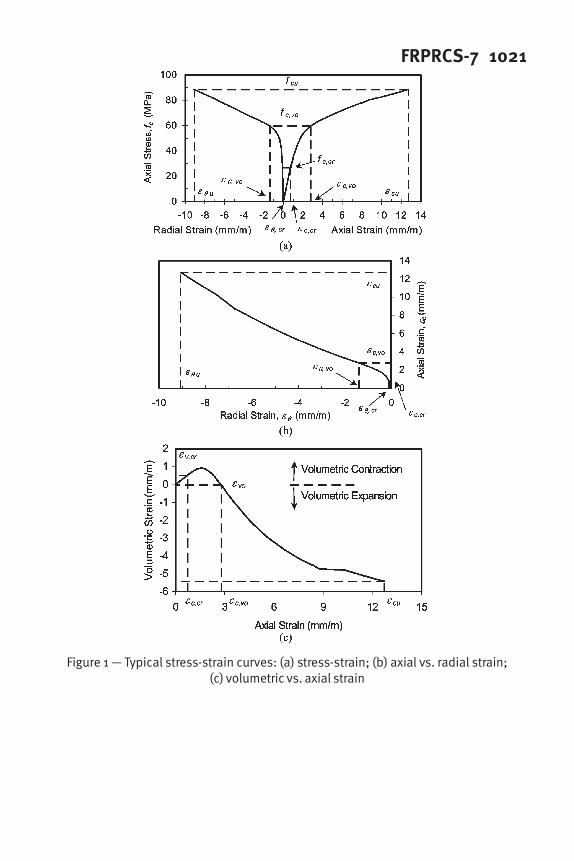
The typical uniaxial stress-strain behavior of concrete circular columns confined
by transverse FRP composite reinforcement is shown in Figure 1. Figure 1a describes the
overall stress versus axial and radial strain response to monotonically increasing axial
compressive strain, induced under displacement control. Figure 1b describes the axial
strain versus radial strain relationship in which the sign convention used is that
compressive stress and strain are positive and tensile radial strain is negative. Figure 1c
shows the volumetric strain εv of Eq. (1) versus axial strain,
θεεε 2+=
cv
(1)
where εc = axial compressive strain; and ε
θ = radial strain. From Figure 1, three stress-
strain regimes are identified.
Linear Elastic Response Regime
The initial response of FRP-confined concrete follows a similar behavior to
unconfined concrete since radial expansion of the concrete core is insignificant
(Mirmiran and Shahawy1
; Xiao and Wu8
) and the FRP composite jacket does not change
substantially the column stiffness. As the imposed axial strain increases, microcracking
of the concrete core starts to accumulate and radial strain increases faster than axial
strain. Therefore, the nonlinear response deviates from elastic theory. This regime is
valid for a radial strain range 0 ≤ |εθ
| ≤ |εθ,cr
| and corresponding axial compression strain

1014 Saenz and Pantelidesrange 0 ≤ ε
c ≤ ε
c,cr. It is limited by initiation of microcracking in the concrete, which
occurs at a radial strain of εθ,cr
= -0.1 mm/m (Saenz9
). Consequently, in the linear elastic
response regime the stress-strain response can be calculated using Eqs. 2 to 5.
crc
cr
c
,
,
ε
ε
ν
θ
−= (2)
( )ccv
ενε 21−= (3)
cccEf ε= (MPa) (4)
'
5700ccfE = (MPa) (5)
where vc = Poisson’s ratio; ε
c,cr = axial compressive strain at ε
θ,cr = -0.1 mm/m; f
c = axial
compressive stress; f’
c = concrete compressive strength; and E
c = concrete modulus of
elasticity. For normal weight concrete the Poisson’s ratio is in the range of 0.15-0.25,
which in this paper it is assumed as vc = 0.20. The initial stress-strain relationship of Eq
.4 is found using Hooke’s Law for the linear elastic response regime.
Transition Regime
The second or transition regime is valid for a radial strain range |εθ,cr
| ≤ |εθ
| ≤
|εθ,vo
| and corresponding axial compression strain range εc,cr
≤ εc ≤ ε
c,vo. In this regime
the FRP composite jacket starts to counteract the stiffness degradation of the concrete
core in which the volumetric strain response is reversed from volumetric contraction to
volumetric expansion or dilation, as shown in Figure 1c. As the imposed axial strain
increases, damage starts to accumulate, thus increasing the radial expansion at a higher
rate than the imposed axial strain. As a result, the initial volumetric contraction is
reversed until it becomes zero, as shown in Figure 2.
The fundamental and physical stress-strain behavior within the transition regime
can be described using Eqs. 6 to 8.
c
crcvoc
crcc
voc
c
cc
−
−
−
−−=
,,
,
,
2
21
εε
εε
ε
ν
ενεθ
(6)
β
εθ
2
1
1
sec
+
=c
EE (7)
cc
Ef εsec
= (8)
where c = rate of unstable volumetric growth with increasing axial compressive strain,
which for normal weight concrete is approximately c = 2; Esec
= secant concrete
modulus, defined in Figure 3; and β = secant modulus softening rate.
Pantazopoulou and Mills2
proposed that internal damage in the concrete could
be measured by estimating the volumetric growth of concrete, or the amount of expansion

FRPRCS-7 1015of the concrete core area resisting the uniaxial load. This concept is adopted herein to
reflect quantitatively the softening resistance of FRP-confined concrete as a function of
the area strain (εa = 2ε
θ), as defined in Eqs. 6 and 7. As the imposed axial strain
increases, the volumetric strain becomes zero, identified as εvo
in Figure 1c and Figure 2,
and marks the beginning of volumetric expansion or effective dilation response of the
FRP composite jacket.
Ultimate Axial Stress-Radial Strain Regime
In the third regime, the axial stress versus radial strain behavior up to failure is
controlled by the lateral kinematic restraint of the FRP composite jacket until the ultimate
radial strain is reached. In terms of the axial stress versus radial strain relationship, it is
mostly linear, as shown in Figure 1a. This regime is valid for a radial strain range |εθ,vo
|
≤ |εθ
| ≤ | εθu
|, and the corresponding axial compression strain range εc,vo
≤ εc ≤ ε
cu.
This regime depends on the ultimate radial to axial strain ratio, defined in Eq. 9,
which is a function of the normalized effective confining stiffness of the FRP composite
jacket, defined in Eq. 10
2
1
C
je
cu
u
pKC
−
=−=
ε
ε
µ
θ
(9)
'
2
c
ff
je
fD
Et
K = (10)
where µp = ultimate radial to axial strain ratio; C
1 and C
2 = experimental constants; K
je =
normalized effective confining stiffness; tf = total thickness of FRP composite jacket
reinforcement; Ef = FRP composite tensile modulus; and D = concrete column diameter.
The significance of Eq. 9 is that knowing the ultimate radial strain of the FRP
composite, which is related to the mechanical properties of the FRP composite laminate,
the ultimate axial compressive strain could be calculated. In both the transition and the
ultimate axial stress-radial strain regimes, the degree of damage is best represented by the
amount of radial expansion of the concrete caused by microcracking. Since the FRP
composite jacket is essentially a linear elastic material, the kinematic restraint of the
concrete is linearly controlled by the amount of deformation in the FRP composite jacket.
This is valid until failure or rupture of the FRP composite reinforcement is reached,
which determines the ultimate radial strain of the FRP-confined concrete column.
Therefore, Eq. 8 could again be used to calculate the ultimate compressive axial stress of
the FRP-confined concrete circular column at εc = ε
cu corresponding to ε
θ = ε
θu.
In order to determine the complete third stress-strain regime response, the axial
stress-radial strain relationship is obtained from experiments and is found to be linear
(Saenz9
), as shown in Figure 4. The axial compressive stress for radial strain in the range
|εθ,vo
| ≤ |εθ| ≤ | ε
θu| is:

1016 Saenz and Pantelides( )
vocvotc
fEf,,,
+−=θθθ
εε (11)
uvo
voccu
t
ff
E
θθ
θ
εε −
−
=
,
,
(12)
where fcu
= ultimate compressive axial stress; fc,vo
= axial stress at εθ,vo
, calculated using
Eq. 8; and Eθt
= tangent radial modulus. Finally, the axial compressive strain can be
found by using Eq. 8.
PHYSICAL SIGNIFICANCE OF VARIABLES
The physical and experimental evaluation of variables is based on 108 FRP-
confined concrete circular column tests in which epoxy and urethane resin-matrix,
utilizing carbon and glass fibers were applied (Saenz9
).
Radial and Axial Strain at Zero Volumetric Strain
The radial strain and corresponding axial strain at zero volumetric strain mark
the effective dilation response of the FRP composite jacket. Pantazopoulou and Mills2
found that porosity, which is an indicator of voids in the microstructure of solid concrete,
as well as strain-induced damage, could be represented by radial strain dilation and secant
modulus softening, as shown in Eqs. 6 and 7. The specific value of the axial strain
corresponding to zero volumetric strain (εc,vo
in Figure 1a) should decrease with
mechanically induced loading. On the other hand, εc,vo
should increase for high-strength
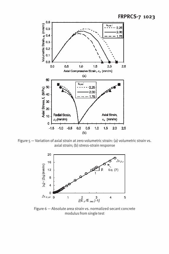
concrete which is characterized by its low porosity. Figure 5a compares the volumetric
versus axial strain for different values of εc�vo
, and Figure 5b compares the corresponding
stress-strain response. Both figures are calculated assuming that the other important
variables are constant and are only plotted for the first and second regimes in the range 0
≤ εc ≤ ε
c,vo. It can be observed that the lower the value of ε
c�vo the lower the stress-strain
response, meaning that mechanically induced cracking could accelerate the degree of
internal concrete damage. Notice that in Figure 5a, the dark symbols show the exact
location of εc,vo
for the three values, and in Figure 5b the dark symbols show the
corresponding values of axial strain, radial strain and axial stress.
Based on experimental results, the average axial strain at zero volumetric strain
is found to be εc,vo
= 2.06 mm/m (Saenz9
). This result agrees with Imran and
Pantazopoulou10
, who found that εc,vo
, which is equal to the axial compressive strain at
the corresponding peak stress εco
, for unconfined concrete, was between 1.5 mm/m to 3.5
mm/m. The significance of this result is that the initial stiffness of the concrete column
controls the degree of damage, until the FRP composite reinforcement jacket is fully
engaged.
Ultimate Radial to Axial Compressive Strain Ratio
The ultimate radial to axial compressive strain ratio µp defined in Eq. 9. The
experimental constants C1 and C
2 were found based on experiments (Saenz
9
) as:

FRPRCS-7 1017
63.0
21.6
−
=
jepKµ (13)
The physical significance of this relationship is that knowing the normalized
effective confinement stiffness and the ultimate radial strain εθu
, which is a function of
the FRP composite laminate mechanical properties, the ultimate axial strain can be
determined. Moran and Pantelides11
derived an equivalent expression by using a
different set of experimental data from the literature, where experimental constants C1
and C2 in Eq. (13) were found as follows: C
1 varied between 4.635 and 5.50 and C
2 =
-0.67.
Ultimate Radial Strain
The ultimate radial strain of the FRP-confined circular concrete column is
reached when failure or rupture of the FRP composite jacket occurs. Since the FRP
composite jacket is essentially a linear elastic material, the kinematic restraint of the
concrete is linearly controlled by the amount of deformation in the FRP composite jacket.
Based on 108 experiments of 150 x 300 mm FRP-confine concrete cylinders (Saenz9
), the
ultimate radial strain εθu
was found to be smaller than the ultimate tensile strain of FRP
tensile coupons εfu
. Therefore, εθu
could be expressed as:
fufu
εξεθ
= 0.10 ≤≤f
ξ (14)
where ξf = FRP composite effectiveness. Based on the same experimental study, carbon-
epoxy resin FRP composites have an average ξf,CE
= 0.66; carbon-urethane and glass-
urethane resin FRP composites have an average ξf,U
= 0.85.
Secant Modulus Softening Rate
The secant modulus softening rate β, represents the slope of the area strain
versus the normalized secant concrete modulus, as shown in Figure 6. The secant
concrete modulus decreases with increasing void area ratio, meaning that the rate of
change of the secant concrete modulus is applicable for the entire stress-strain response,
as shown in Eq. 7 and Figure 3. This is attributed to the continuous growth of cracks
with increased imposed axial compressive strains. The increase in void area ratio or area
strain εa is limited by the ultimate radial strain as shown in Eq. (9). From Figure 7 it can
be observed that µp decreases as the normalized effective confining stiffness K
je
increases. Therefore, by knowing the ultimate radial to axial compressive strain ratio µp
and secant modulus softening rate relationship β, the second and third stress-strain
regimes can be described. Based on experimental results, the following expression was
found (Saenz9
):
( )3
1044.141.3
−
×+−=p
µβ (15)
The physical significance of Eq. 15 is that the rate of void area ratio or softening
of the secant concrete stiffness depends on the normalized effective confinement stiffness
Kje. The higher the value of K
je the smaller the ultimate radial to axial compressive strain

1018 Saenz and Pantelidesµ
p, and the higher the secant modulus softening rate β. Hence, by knowing the initial
mechanical properties of the materials, the entire stress-strain curve could be described.
Figure 8 compares the theoretical stress-strain response for three different
normalized effective confinement stiffness values. It is evident from Figure 8a that
within the transition zone, the lower the value of Kje the higher is the axial compression
stress. This phenomenon is the result of early FRP jacket effective dilation, which
rapidly counteracts concrete stiffness degradation. Therefore, the area strain increases at
a much greater rate than the imposed uniaxial strain because of the lower Kje. For axial
strains beyond the transition zone and for a fixed axial strain, a much lower radial strain
response is obtained as Kje increases, as shown in Figure 8b. From Figure 8c it can be
observed that the lower the value of Kje, the more severe the internal damage in the
confined concrete. In addition, for high values of Kje, the volumetric dilation or
expansion could be reversed and volumetric contraction could be achieved once again at
high axial compressive strains. This phenomenon is the result of high plastic strain
ductility, meaning that the axial compressive strain increases at a higher rate than the
radial strain, so that the volumetric strain defined in Eq. 1 would become positive once
again. Furthermore, for high values of Kje the typical failure mode is a brittle-explosive
type caused by the high degree of pore collapse or compaction of the porous concrete
structure, and the high lateral strain confinement restraint due to the passive action of the
FRP jacket.
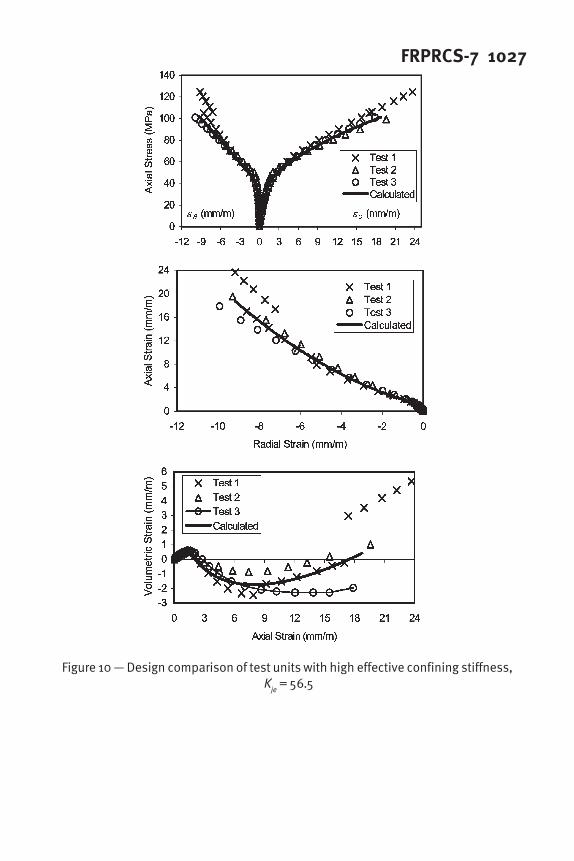
CONFINEMENT MODEL ASSESSMENT
Assessment of the confinement model for moderate and high normalized
effective confinement stiffness Kje is presented in Figures 9 and 10, and compared with
experimental results (Saenz9
). Figure 9 shows the calculated stress-strain response for
specimens with moderate normalized effective confinement stiffness (Kje = 27.2); and
Fig. 10 shows the calculated stress-strain response for specimens with high normalized
effective confinement stiffness (Kje = 56.5). For each value of K
je three test units are
compared with the proposed confinement model. Clearly, variability of the experimental
data exits when tested under the same conditions, but the confinement model captures the
characteristics of the behavior in a satisfactory manner.
CONCLUSIONS
A constitutive strain-based confinement model for FRP-confined circular
concrete columns was developed, which is well suited for analysis and design because it
does not depend on the level of axial stress directly. The FRP composite confined
concrete stiffness and internal damage are determined from the radial strain, which
represents the amount of internal microcracking with respect to the initial properties of
concrete. The radial and corresponding axial strain at zero volumetric strain, mark the
beginning of the effective dilation response of the FRP composite jacket. The secant
modulus softening rate and ultimate radial to axial strain relationship were developed,
and were found to be functions of the normalized effective confining stiffness. The
ultimate radial strain of the FRP-confined concrete column is expressed as a function of

FRPRCS-7 1019the FRP composite effectiveness. The entire stress-strain response was determined and
found to be in good agreement with experiments results.
ACKNOWLEDGMENTS
The writers acknowledge the financial support of the National Science Foundation under
Grant No. CMS 0099792. They also acknowledge the assistance of Professor Lawrence
D. Reaveley and graduate students at the University of Utah. The writers acknowledge
Sika Corporation; Air Logistics Corporation and Eagle Precast Inc. for in-kind support.
NOTATION
The following symbols are used in this paper:
c = rate of unstable volumetric growth
D = concrete column diameter
Ec = concrete modulus of elasticity
Ef = FRP composite tensile modulus
Esec
= secant concrete modulus
Eθt
= tangent radial modulus
f’c = concrete compressive strength
fc = axial compressive stress
fc,vo
= axial stress at εθ,vo
fcu
= ultimate compressive axial stress
Kje = normalized effective confining stiffness
tf = total thickness of FRP composite jacket reinforcement
β = secant modulus softening rate
εa = area strain
εc = axial compressive strain
εc,cr
= concrete cracking axial compressive strain
εc,vo
= axial strain at zero volumetric strain
εcu
= ultimate axial compressive strain
εfu
= ultimate FRP tensile strain
εv = volumetric strain
εθ,cr
= concrete cracking radial strain
εθu
= ultimate radial strain
εθ= radial strain
εθ�vo
= radial strain at zero volumetric strain
µp = ultimate radial to axial strain ratio
νc = Poisson’s ratio
ξf = FRP composite effectiveness

1020 Saenz and PantelidesREFERENCES
1. Mirmiran, A., and Shahawy, M. (1997), “Behavior of Concrete Columns Confined by
Fiber Composites,” Journal of Structural Engineering., ASCE, 123(5), 583-590.
2. Pantazopoulou, S. J., and Mills, R. H. (1995), “Microstuctural Aspects of the
Mechanical Response of Plain Concrete.” ACI Materials Journal, 92(6), 605-616.
3. Richart, R. D., Brandtzaeg, A., and Brown, R. L. (1929), “The Failure of Plain and
Spiral Reinforced Concrete in Compression.” Engineering Experiment Station Bulletin
No. 190, University of Illinois, Urbana.
4. Mander, J. B., Preistley, M. J. N., and Park, R. (1988), “Theoretical Stress-Strain
Model For Confined Concrete.” Journal of Structural Engineering., ASCE, 114(8),
1804-1826.
5. Richard, R. M., and Abbott, B. J. (1975), “Versatile Elastic-Plastic Stress-Strain
Formula.” Journal of the Engineering Mechanics, ASCE, 101(EM4), 511-515.
6. Spoelstra, M. R., and Monti, G. (1999), “FRP Confined Concrete Model,” Journal of
Composites for Construction, ASCE, 3(3), 143-150.
7. Moran, A. D., and Pantelides, C. P. (2005), “Damage-Based Stress-Strain Model for
Fiber-Reinforced Polymer-Confined Concrete.” ACI Structural Journal, 102(1), 54-61.
8. Xiao, Y., and Wu, H. (2000), “Compressive Behavior of Concrete Confined by
Carbon Fiber Composite Jackets.” Journal of Materials in Civil Engineering, ASCE,
12(2), 139-146.
9. Saenz, N. (2004), “Durability and Design of Fiber Reinforced Polymer Composites
for Concrete Confinement.” Ph.D. Dissertation, Dept. of Civil & Envir. Eng., University
of Utah, Salt Lake City, Utah.
10. Imran, I., and Pantazopoulou, S. J. (1996), “Experimental Study of Plain Concrete
Under Triaxial Stress.” ACI Materials Journal, Vol. 93, No. 6, November, 589-601.
11. Moran, A. D., and Pantelides, C. P. (2002), “Variable Strain Ductility Ratio for
Fiber-Reinforced Polymer Confined Concrete.” Journal of Composites for Construction,
ASCE, 6(4), 224-232.
FRPRCS-7 1021
Figure 1 — Typical stress-strain curves: (a) stress-strain; (b) axial vs. radial strain;(c) volumetric vs. axial strain

1022 Saenz and Pantelides
Figure 2 — Typical volumetric vs. radial strain curve
Figure 3 — Concrete modulus and secant concrete modulus definition
Figure 4 — Tangent radial modulus of elasticity from single test
FRPRCS-7 1023
Figure 5 — Variation of axial strain at zero volumetric strain: (a) volumetric strain vs.axial strain; (b) stress-strain response
Figure 6 — Absolute area strain vs. normalized secant concretemodulus from single test

1024 Saenz and Pantelides
Figure 7 — Ultimate radial to axial compressive strain ratio vs. normalized effectiveconfining stiffness

FRPRCS-7 1025
Figure 8 — Normalized effective stiffness variation response: (a) stress-strain curve;(b) axial vs. radial strain curve; (c) volumetric vs. axial strain curve

1026 Saenz and Pantelides
Figure 9 — Design comparison of test units with moderate effective confining stiffness,K
je = 27.2
FRPRCS-7 1027
Figure 10 — Design comparison of test units with high effective confining stiffness, K
je = 56.5

1028 Saenz and Pantelides


![State-of-the-art Studies on the FRP-confined Concrete · FRP-confined concrete from the various confinement parameters, such as confinement methods, geometry properties, and ... [11]](https://static.fdocuments.in/doc/165x107/60cd06c9d99279430362b3c7/state-of-the-art-studies-on-the-frp-confined-concrete-frp-confined-concrete-from.jpg)
![MECHANICAL BEHAVIOUR OF FRP-CONFINED ......It was found in [1] that the ultimate hoop strain values from the confined specimen tests is significantly lower than the values obtained](https://static.fdocuments.in/doc/165x107/60cd06c9d99279430362b3c9/mechanical-behaviour-of-frp-confined-it-was-found-in-1-that-the-ultimate.jpg)


![Behaviour of frp confined normal and high strength concrete [autosaved]](https://static.fdocuments.in/doc/165x107/55a39ede1a28ab931f8b45d2/behaviour-of-frp-confined-normal-and-high-strength-concrete-autosaved.jpg)