STRAIGHT EJECTOR PINS - th.misumi-ec.com · STRAIGHT EJECTOR PINS -L DIMENSION DESIGNATION...
1
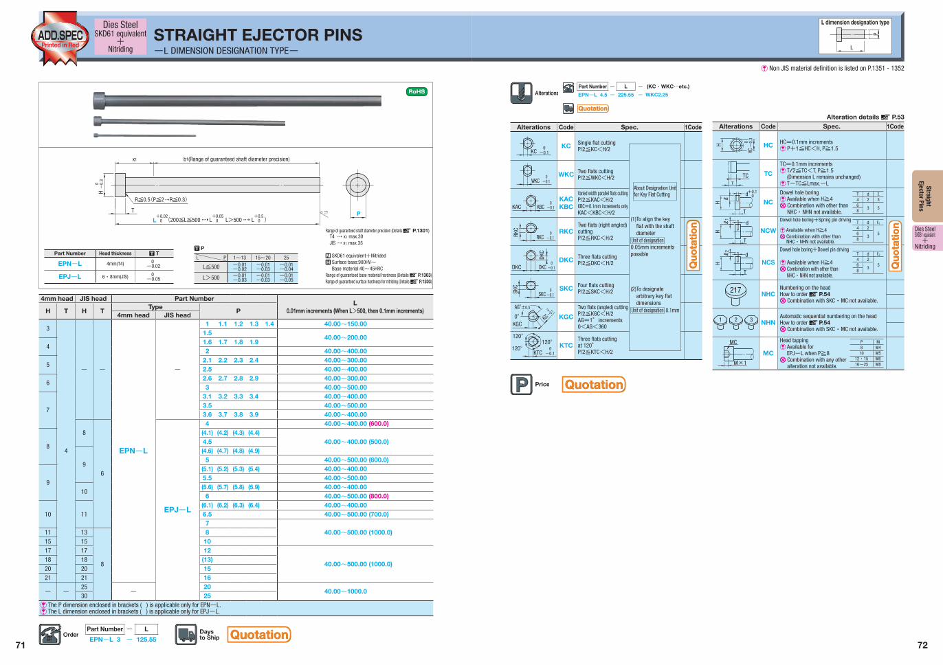
71 72 Straight Ejector Pins Dies Steel SKD61 equivalent + Nitriding STRAIGHT EJECTOR PINS -L DIMENSION DESIGNATION TYPE- R SKD61 equivalent+Nitrided Q Surface base:900HV~ Base material:40~45HRC Range of guaranteed base material hardness (Details X P.1303) Range of guaranteed surface hardness for nitriding (Details X P.1303) Part Number - L EPN-L 3 - 125.55 L P L dimension designation type 4mm head JIS head Part Number L 0.01mm increments (When L>500, then 0.1mm increments) H T H T Type P 4mm head JIS head 3 4 - - EPN-L - 1 1.1 1.2 1.3 1.4 40.00~150.00 1.5 40.00~200.00 4 1.6 1.7 1.8 1.9 2 40.00~400.00 5 2.1 2.2 2.3 2.4 40.00~300.00 2.5 40.00~400.00 6 2.6 2.7 2.8 2.9 40.00~300.00 3 40.00~500.00 7 3.1 3.2 3.3 3.4 40.00~400.00 3.5 40.00~500.00 3.6 3.7 3.8 3.9 40.00~400.00 8 6 EPJ-L 4 40.00~400.00 (600.0) 8 (4.1) (4.2) (4.3) (4.4) 40.00~400.00 (500.0) 4.5 9 (4.6) (4.7) (4.8) (4.9) 5 40.00~500.00 (600.0) 9 (5.1) (5.2) (5.3) (5.4) 40.00~400.00 5.5 40.00~500.00 10 (5.6) (5.7) (5.8) (5.9) 40.00~400.00 6 40.00~500.00 (800.0) 10 11 (6.1) (6.2) (6.3) (6.4) 40.00~400.00 6.5 40.00~500.00 (700.0) 7 40.00~500.00 (1000.0) 11 13 8 8 15 15 10 17 17 12 40.00~500.00 (1000.0) 18 18 (13) 20 20 15 21 21 16 - - 25 - 20 40.00~1000.0 30 25 V The P dimension enclosed in brackets ( ) is applicable only for EPN-L. V The L dimension enclosed in brackets ( ) is applicable only for EPJ-L. Dies Steel SKD61 equivalent + Nitriding Alterations Code Spec. 1Code KC 0 -0.1 KC Single flat cutting P/2≦KC<H/2 WKC 0 -0.1 WKC Two flats cutting P/2≦WKC<H/2 KAC KBC 0 -0.1 KAC KBC Varied width parallel flats cutting P/2≦KAC<H/2 KBC=0.1mm increments only KAC<KBC<H/2 RKC RKC 0 -0.1 RKC Two flats (right angled) cutting P/2≦RKC<H/2 DKC DKC DKC 0 -0.1 DKC Three flats cutting P/2≦DKC<H/2 SKC SKC 0 -0.1 SKC Four flats cutting P/2≦SKC<H/2 ±0.5 0° KGC AG° 0 -0.1 KGC KGC Two flats (angled) cutting P/2≦KGC<H/2 AG=1°increments 0<AG<360 KTC 0 120° 120° -0.1 120° KTC Three flats cutting at 120° P/2≦KTC<H/2 Part Number - L - (KC・WKC…etc.) EPN-L 4.5 - 225.55 - WKC2.25 About Designation Unit for Key Flat Cutting (1)To align the key flat with the shaft diameter Unit of designation 0.05mm increments possible (2)To designate arbitrary key flat dimensions Unit of designation 0.1mm Alterations Code Spec. 1Code H HC 0 -0.3 HC HC=0.1mm increments V P+1≦HC<H, P≧1.5 T TC TC TC=0.1mm increments V T/2≦TC<T, P≧1.5 (Dimension L remains unchanged) V T-TC≦Lmax.-L H T +0.1 0 d ℓ NC Dowel hole boring V Available when H≧4 U Combination with other than NHC・NHN not available. ℓ 1 H T d NCW Dowel hole boring+Spring pin driving V Available when H≧4 U Combination with other than NHC・NHN not available. ℓ 2 H T d NCS Dowel hole boring+Dowel pin driving V Available when H≧4 U Combination with other than NHC・NHN not available. 217 NHC Numbering on the head How to order X P.54 U Combination with SKC・MC not available. 2 1 3 NHN Automatic sequential numbering on the head How to order X P.54 U Combination with SKC・MC not available. M×1 MC MC Head tapping V Available for EPJ-L when P≧8 U Combination with any other alteration not available. T d ℓ1 4 2 5 6 3 8 T d ℓ2 4 2 5 6 3 8 P M 8 M4 10 M5 12・15 M6 16~25 M8 T d ℓ 4 2 3 6 3 5 8 Alteration details X P.53 P 1.6 x1 T L +0.02 0 (200≦L≦500 L>500 ) L +0.05 0 L +0.5 0 H 0 -0.3 R≦0.5 (P≦2 R≦0.3) b1(Range of guaranteed shaft diameter precision) Part Number Head thickness T T EPN-L 4mm(T4) 0 -0.02 EPJ-L 6・8mm(JIS) 0 -0.05 L P 1~13 15~20 25 L≦500 -0.01 -0.02 -0.01 -0.03 -0.01 -0.04 L>500 -0.01 -0.03 -0.01 -0.03 -0.01 -0.05 T P Range of guaranteed shaft diameter precision (Details X P.1301) T4 W x1 max.30 JIS W x1 max.35 Quotation Quotation Quotation Quotation Quotation Quotation Quotation Quotation Quotation Quotation V Non JIS material definition is listed on P.1351 - 1352
Transcript of STRAIGHT EJECTOR PINS - th.misumi-ec.com · STRAIGHT EJECTOR PINS -L DIMENSION DESIGNATION...
71 72
Straight Ejector Pins
Dies SteelSKD61 equivalent
+Nitriding
STRAIGHT EJECTOR PINS-L DIMENSION DESIGNATION TYPE-
R SKD61 equivalent+Nitrided Q Surface base:900HV~
Base material:40~45HRCRange of guaranteed base material hardness (Details X P.1303)Range of guaranteed surface hardness for nitriding (Details X P.1303)
Part Number - L
EPN-L 3 - 125.55
L
P
L dimension designation type
4mm head JIS head Part Number L
0.01mm increments (When L>500, then 0.1mm increments)H T H TType
P4mm head JIS head
3
4
- -
EPN-L
-
1 1.1 1.2 1.3 1.4 40.00~150.00 1.5
40.00~200.00 4
1.6 1.7 1.8 1.92 40.00~400.00
52.1 2.2 2.3 2.4 40.00~300.00 2.5 40.00~400.00
62.6 2.7 2.8 2.9 40.00~300.00 3 40.00~500.00
7
3.1 3.2 3.3 3.4 40.00~400.00 3.5 40.00~500.00 3.6 3.7 3.8 3.9 40.00~400.00
8
6
EPJ-L
4 40.00~400.00 (600.0)
8
(4.1) (4.2) (4.3) (4.4)40.00~400.00 (500.0)4.5
9
(4.6) (4.7) (4.8) (4.9)5 40.00~500.00 (600.0)
9
(5.1) (5.2) (5.3) (5.4) 40.00~400.00 5.5 40.00~500.00
10(5.6) (5.7) (5.8) (5.9) 40.00~400.00
6 40.00~500.00 (800.0)
10 11(6.1) (6.2) (6.3) (6.4) 40.00~400.006.5 40.00~500.00 (700.0)7
40.00~500.00 (1000.0)11 13
8
815 15 1017 17 12
40.00~500.00 (1000.0)18 18 (13)20 20 1521 21 16
- -25
-20
40.00~1000.030 25
V The P dimension enclosed in brackets ( ) is applicable only for EPN-L.V The L dimension enclosed in brackets ( ) is applicable only for EPJ-L.
Dies SteelSKD61 equivalent
+Nitriding
Alterations Code Spec. 1Code
KC0-0.1
KC Single flat cuttingP/2≦KC<H/2
WKC0-0.1
WKC Two flats cuttingP/2≦WKC<H/2
KAC KBC0-0.1
KACKBC
Varied width parallel flats cuttingP/2≦KAC<H/2KBC=0.1mm increments onlyKAC<KBC<H/2
RKC
RKC0-0.1
RKCTwo flats (right angled) cuttingP/2≦RKC<H/2
DKC
DKC
DKC0-0.1
DKC Three flats cuttingP/2≦DKC<H/2
SKC
SKC0-0.1
SKC Four flats cuttingP/2≦SKC<H/2
±0.5
0°KGC
AG°0-0.1
KGC KGC
Two flats (angled) cuttingP/2≦KGC<H/2AG=1°increments0<AG<360
KTC0120°
120°
-0.1
120° KTCThree flats cuttingat 120°P/2≦KTC<H/2
Part Number - L - (KC・WKC…etc.)
EPN-L 4.5 - 225.55 - WKC2.25
About Designation Unit for Key Flat Cutting
(1) To align the key flat with the shaft diameter
Unit of designation0.05mm increments possible
(2) To designate arbitrary key flat dimensions
Unit of designation 0.1mm
Alterations Code Spec. 1Code
H
HC0-
0.3
HC HC=0.1mm incrementsV P+1≦HC<H, P≧1.5
T
TC TC
TC=0.1mm incrementsV T/2≦TC<T, P≧1.5
(Dimension L remains unchanged)V T-TC≦Lmax.-L
H
T
+0.10d
ℓ NC
Dowel hole boringV Available when H≧4U Combination with other than
NHC・NHN not available.
ℓ1
H
T
dNCW
Dowel hole boring+Spring pin driving
V Available when H≧4U Combination with other than
NHC・NHN not available.
ℓ2
H
T
dNCS
Dowel hole boring+Dowel pin driving
V Available when H≧4U Combination with other than
NHC・NHN not available.
217 NHCNumbering on the headHow to order X P.54U Combination with SKC・MC not available.
21 3 NHNAutomatic sequential numbering on the headHow to order X P.54U Combination with SKC・MC not available.
M×1
MC
MC
Head tappingV Available for
EPJ-L when P≧8U Combination with any other
alteration not available.
T d ℓ1
4 256
38
T d ℓ2
4 256
38
P M8 M4
10 M512・15 M616~25 M8
T d ℓ4 2 36
3 58
Alteration details X P.53
P1.6
x1
T
L+0.02 0 (200≦L≦500 L>500 )L
+0.05 0 L
+0.5 0
H
0-
0.3
R≦0.5(P≦2 R≦0.3)
b1(Range of guaranteed shaft diameter precision)
Part Number Head thickness T T
EPN-L 4mm(T4) 0-0.02
EPJ-L 6・8mm(JIS) 0-0.05
L P 1~13 15~20 25
L≦500 -0.01-0.02
-0.01-0.03
-0.01-0.04
L>500 -0.01-0.03
-0.01-0.03
-0.01-0.05
T P
Range of guaranteed shaft diameter precision (Details X P.1301)T4 W x1 max.30JIS W x1 max.35
QuotationQuotation
QuotationQuotation
QuotationQuotation
Quo
tati
on
Quo
tati
on
Quo
tati
on
Quo
tati
on
V Non JIS material definition is listed on P.1351 - 1352