STR91xFA in-application programming (IAP) over Ethernet
24
February 2008 Rev 1 1/24 AN2675 Application note STR91xFA in-application programming (IAP) over Ethernet Introduction The STR912 is an ideal microcontroller for applications running on a network. With its Ethernet MAC interface and the capability to operate at 96 MHz, it provides a high performance solution for network-embedded applications. This application note demonstrates how to use In-Application Programming (IAP) through the Ethernet interface. Two solutions are provided, the first using the TFTP protocol and the second using the HTTP protocol. www.st.com
Transcript of STR91xFA in-application programming (IAP) over Ethernet

February 2008 Rev 1 1/24
AN2675Application note
STR91xFA in-application programming (IAP) over Ethernet
IntroductionThe STR912 is an ideal microcontroller for applications running on a network. With itsEthernet MAC interface and the capability to operate at 96 MHz, it provides a highperformance solution for network-embedded applications.
This application note demonstrates how to use In-Application Programming (IAP) throughthe Ethernet interface. Two solutions are provided, the first using the TFTP protocol and thesecond using the HTTP protocol.
www.st.com
Contents AN2675
2/24
Contents
1 Theory of operation . . . . . . . . . . . . . . . . . . . . . . . . . . . . . . . . . . . . . . . . . 3
1.1 IAP overview . . . . . . . . . . . . . . . . . . . . . . . . . . . . . . . . . . . . . . . . . . . . . . . 3
1.2 IAP using Ethernet on STR9 . . . . . . . . . . . . . . . . . . . . . . . . . . . . . . . . . . . 3
1.2.1 Ethernet interface . . . . . . . . . . . . . . . . . . . . . . . . . . . . . . . . . . . . . . . . . . 3
1.2.2 IAP using Ethernet . . . . . . . . . . . . . . . . . . . . . . . . . . . . . . . . . . . . . . . . . . 3
1.2.3 Application layer . . . . . . . . . . . . . . . . . . . . . . . . . . . . . . . . . . . . . . . . . . . . 4
2 IAP using TFTP . . . . . . . . . . . . . . . . . . . . . . . . . . . . . . . . . . . . . . . . . . . . . 6
2.1 TFTP protocol overview . . . . . . . . . . . . . . . . . . . . . . . . . . . . . . . . . . . . . . . 6
2.2 DHCP protocol overview . . . . . . . . . . . . . . . . . . . . . . . . . . . . . . . . . . . . . . 7
2.3 IAP method . . . . . . . . . . . . . . . . . . . . . . . . . . . . . . . . . . . . . . . . . . . . . . . . 8
2.4 Running the IAP application . . . . . . . . . . . . . . . . . . . . . . . . . . . . . . . . . . . 11
2.4.1 User project configuration . . . . . . . . . . . . . . . . . . . . . . . . . . . . . . . . . . . 11
2.4.2 PC configuration . . . . . . . . . . . . . . . . . . . . . . . . . . . . . . . . . . . . . . . . . . 11
2.4.3 How to start IAP operation . . . . . . . . . . . . . . . . . . . . . . . . . . . . . . . . . . . 13
2.5 Driver description . . . . . . . . . . . . . . . . . . . . . . . . . . . . . . . . . . . . . . . . . . . 15
3 IAP using HTTP . . . . . . . . . . . . . . . . . . . . . . . . . . . . . . . . . . . . . . . . . . . . 16
3.1 HTTP overview . . . . . . . . . . . . . . . . . . . . . . . . . . . . . . . . . . . . . . . . . . . . . 16
3.2 Request methods . . . . . . . . . . . . . . . . . . . . . . . . . . . . . . . . . . . . . . . . . . . 16
3.3 Uploading files with HTTP . . . . . . . . . . . . . . . . . . . . . . . . . . . . . . . . . . . . 16
3.4 IAP method . . . . . . . . . . . . . . . . . . . . . . . . . . . . . . . . . . . . . . . . . . . . . . . 17
3.5 Running the IAP application . . . . . . . . . . . . . . . . . . . . . . . . . . . . . . . . . . . 20
3.5.1 User project configuration . . . . . . . . . . . . . . . . . . . . . . . . . . . . . . . . . . . 20
3.5.2 How to start IAP operation . . . . . . . . . . . . . . . . . . . . . . . . . . . . . . . . . . . 20
3.6 Driver description . . . . . . . . . . . . . . . . . . . . . . . . . . . . . . . . . . . . . . . . . . . 22
4 Revision history . . . . . . . . . . . . . . . . . . . . . . . . . . . . . . . . . . . . . . . . . . . 23
AN2675 Theory of operation
3/24
1 Theory of operation
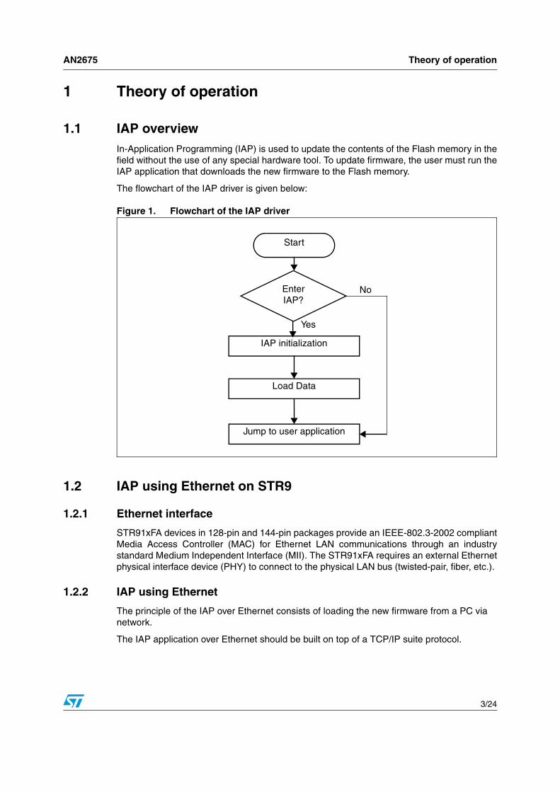
1.1 IAP overviewIn-Application Programming (IAP) is used to update the contents of the Flash memory in thefield without the use of any special hardware tool. To update firmware, the user must run theIAP application that downloads the new firmware to the Flash memory.
The flowchart of the IAP driver is given below:
Figure 1. Flowchart of the IAP driver
1.2 IAP using Ethernet on STR9
1.2.1 Ethernet interface
STR91xFA devices in 128-pin and 144-pin packages provide an IEEE-802.3-2002 compliantMedia Access Controller (MAC) for Ethernet LAN communications through an industrystandard Medium Independent Interface (MII). The STR91xFA requires an external Ethernetphysical interface device (PHY) to connect to the physical LAN bus (twisted-pair, fiber, etc.).
1.2.2 IAP using Ethernet
The principle of the IAP over Ethernet consists of loading the new firmware from a PC via network.
The IAP application over Ethernet should be built on top of a TCP/IP suite protocol.
Start
Enter IAP?
IAP initialization
Load Data
Jump to user application
No
Yes

Theory of operation AN2675
4/24
Figure 2. IAP using Ethernet
The full TCP/IP suite consists of numerous protocols, ranging from the low level protocol tothe application level protocol.
The TCP/IP suite uses encapsulation to provide abstraction of protocols and services.Generally, a protocol at a higher level uses a protocol at a lower level to help it fulfil itspurpose.
Figure 3. Example of TCP/IP encapsulation
The control of the physical layer is performed by the ENET FWLib, which is the Ethernetdriver developed by STMicroelectronics for the STR91xFA MAC/DMA controller (ENET). Formore information please refer to STR91xFA ENET Firmware Library User Manual(UM0248).
1.2.3 Application layer
The Application Layer is in charge of loading the file. The TCP/IP stack provides dedicatedsolutions for file loading over network, such as the Trivial File Transfer Protocol (TFTP)which is a very simple file transfer protocol.
This protocol transfers files from a server following a request. Therefore, you must haveTFTP server on the network to perform file loading.
Binary file of the new firmware
STR912F board
PC
TCP/IP
Application Data
TCP/UDP header
IP header
Ethernet header
Application Data
TCP Segment
IP Datagram
Physical Encapsulation
Ethernet frame
FCS

AN2675 Theory of operation
5/24
Another way to load data, without using a server, is to use the HyperText Transfer Protocol(HTTP). HTTP provides file uploading solutions using HTML forms.
Both IAP methods, using the TFTP and HTTP protocols, are described in the next sections.

IAP using TFTP AN2675
6/24
2 IAP using TFTP
This method uses dynamic IP address assignment. A DHCP server is needed for thispurpose. The following sections give an introduction to the TFTP and DHCP protocols.
2.1 TFTP protocol overviewTrivial File Transfer Protocol (TFTP) is a very simple file transfer protocol, with thefunctionality of a very basic form of FTP. Since it is so simple, it is easy to implement in avery small amount of memory, an important consideration for embedded applications.
A transfer begins with a request to read a file, which also serves to request a connection. Ifthe server grants the request, the connection is opened and the file is sent in fixed lengthblocks of 512 bytes. Each data packet contains one block of data, and must beacknowledged by an acknowledgment packet before the next packet can be sent. A datapacket of less than 512 bytes signals the termination of a transfer.
TFTP supports five types of packets, all of which have been mentioned above:
The TFTP header of a packet contains the opcode associated with that packet.
Table 1. TFTP opcode packet
Opcode Operation
1 Read request (RRQ)
2 Write request (WRQ)
3 Data
4 Acknowledgment (ACK)
5 Error
AN2675 IAP using TFTP
7/24
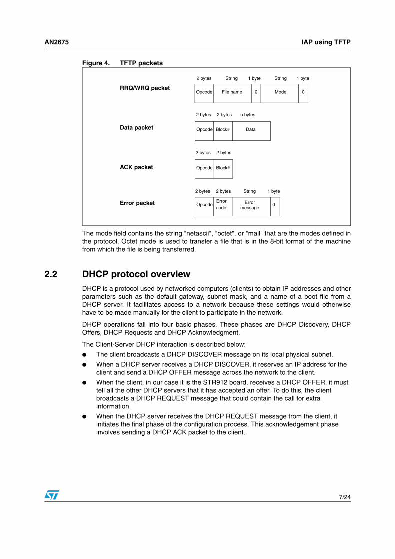
Figure 4. TFTP packets
The mode field contains the string "netascii", "octet", or "mail" that are the modes defined inthe protocol. Octet mode is used to transfer a file that is in the 8-bit format of the machinefrom which the file is being transferred.
2.2 DHCP protocol overviewDHCP is a protocol used by networked computers (clients) to obtain IP addresses and otherparameters such as the default gateway, subnet mask, and a name of a boot file from aDHCP server. It facilitates access to a network because these settings would otherwisehave to be made manually for the client to participate in the network.
DHCP operations fall into four basic phases. These phases are DHCP Discovery, DHCPOffers, DHCP Requests and DHCP Acknowledgment.
The Client-Server DHCP interaction is described below:
● The client broadcasts a DHCP DISCOVER message on its local physical subnet.
● When a DHCP server receives a DHCP DISCOVER, it reserves an IP address for the client and send a DHCP OFFER message across the network to the client.
● When the client, in our case it is the STR912 board, receives a DHCP OFFER, it must tell all the other DHCP servers that it has accepted an offer. To do this, the client broadcasts a DHCP REQUEST message that could contain the call for extra information.
● When the DHCP server receives the DHCP REQUEST message from the client, it initiates the final phase of the configuration process. This acknowledgement phase involves sending a DHCP ACK packet to the client.
2 bytes String 1 byte String 1 byte
Opcode File name 0 Mode 0
Opcode Block# Data
2 bytes 2 bytes n bytes
2 bytes 2 bytes
Opcode Block#
2 bytes 2 bytes String 1 byte
OpcodeErrorcode
Error message
0
RRQ/WRQ packet
Data packet
ACK packet
Error packet

IAP using TFTP AN2675
8/24
Figure 5. DHCP header
2.3 IAP methodThe STR912 client must connect to a TFTP server and request a binary file of the newfirmware. To connect to a server, a client must have an IP address on the network. TheDHCP provides to a client an IP address and a file path.
To implement DHCP and TFTP servers in the PC we have chosen the Tftpd32, which is afreeware package copyrighted 1998-2006 by Philippe Jounin and downloadable from thewebsite: http://tftpd32.jounin.net.
Note: The presence of more than one DHCP server causes incorrect behavior in the application. So make sure that you have only one DHCP server on the network.
Opcode Hardware Type Hardware Addr. Length
Hop Count
Transaction ID
Number of seconds Flags
Client IP Address
Your IP Address
Server IP Address
Gateway IP Address
Client Hardware Address (16 Bytes)
Server Hostname (64 Bytes)
Boot Filename (128 Bytes)
Vendor specific information (64 Bytes)

AN2675 IAP using TFTP
9/24
Figure 6. IAP communication state diagram
DHCP Discover
DHCP Request
TFTP Request
TFTP ACK
End of transmission
TFTP Error
DHCP Offer
DHCP ACK Data received
Data size < 512B
No offer
No ACK
Timeout
Timeout
Timeout
Timeout
Data received
No Data

IAP using TFTP AN2675
10/24
Figure 7. Flowchart of IAP using TFTP
Start
Joystick position in?
IAP initialization
DHCP communication
success
Erase needed sectors
Data received
TFTP Request
Jump to user application
Send ACK
Load Data into Flash memory
TFTP ERROR
No
No
No
No
Yes
Data received <
512B
Yes

AN2675 IAP using TFTP
11/24
2.4 Running the IAP application
2.4.1 User project configuration
● The user application to be loaded must be built at address 0x80000 which is the location of Bank0 if it has been remapped. There is no need to remap Bank0 and Bank1 as this has already been done in the IAP software.
● In the file 91x_fmi.h, uncomment the line "#define Remap_Bank_1" to be compatible with the bank remapping.
An example is provided with this application to show the project settings of a user program which can be loaded in the STR91xFA internal Flash using IAP.
2.4.2 PC configuration
If your local network already supports DHCP and TFTP, you can skip this part and use yourexisting installation.
To implement both DHCP and TFTP servers we will use the Philippe Jounin's TFTPD32software.
● Install and start the TFTPD32. It should look like this:
Figure 8. Tftd32 main dialog box
● Click on the button labeled Settings. This will open a new dialog box.
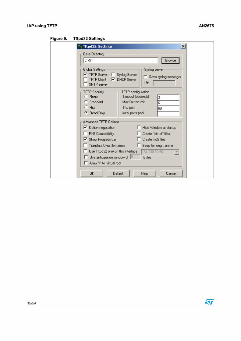
● The Base Directory is the subdirectory of the file to upload. Select your own subdirectory using the browser.
IAP using TFTP AN2675
12/24
Figure 9. Tftpd32 Settings

AN2675 IAP using TFTP
13/24
Figure 10. DHCP Server configuration
● The IAP application has to request an IP address from the DHCP pool. Enter the IP pool starting address and the number of available addresses in the pool. The sample above offers IP addresses from 192.168.0.01 up to and including 192.168.0.07.
● The boot file is the name of the raw binary image of the application you want to upload to the STR912 Flash memory.
● There's no need to specify a WINS/DNS server address or default router unless your IAP application requires direct Internet access. Make sure that the network mask and the IP pool addresses fit your local network configuration.
● Additional Option is used to define the size of the file to download. For this put 13 in the first blank that is the number of the size file option and insert the size of the file in term of 512 bytes in the second, i.e. if the file size is 4 Kbytes you will put 8.
● Finally press Save to let TFTPD32 store the values in the Windows registry and select the TFTP Server tab to return to the initial window.
2.4.3 How to start IAP operation
At reset, the position of the joystick button selects if IAP operation is started or not:
● If the joystick button is pressed in, the IAP starts.
● Else, the system jumps to the user application stored in Bank0.
To use the IAP driver efficiently, please use the following procedure:

IAP using TFTP AN2675
14/24
1. 1. Using the CAPS tool, remap the banks of the Flash memory like this:
Bank 1 at 0x00 and make it the boot bank at power up.
Bank 0 at 0x80000.
2. Using JTAG, load the IAP driver into Bank1.
3. On the host PC, start TFTPD32 and make sure that the configuration is as described in Section 2.4.2: PC configuration.
4. Place the binary file of the new firmware to be loaded in the Base Directory, selected in the TFTPD32, and make sure that the project configuration described Section 2.4.2: PC configuration was respected.
5. Enter the size of the file in number of 512bytes in the option field of the dialog box.
6. Connect the STR912 board to a PC using a crossover Ethernet cable or through an Ethernet switch.
7. If you are using a firewall application, you will need to disable it.
8. Press the reset button while holding the joystick button pressed in to start the IAP process.
9. Finally, if you want to reset your application you have just to press the reset button.

AN2675 IAP using TFTP
15/24
2.5 Driver descriptionIAP using the TFTP driver is built with the same architecture as the TCP/IP model.
The interface Network/Application is composed of layers, which are managed by files takenfrom the Ethernut software.
Ethernut is an open source hardware and software project for building tiny embeddedEthernet devices. For more information please refer to: www.ethernut.de/
The framework of the whole application is implemented in the main file.
Table 2 describes the various files that make up the IAP driver:
In addition, the driver includes the ENET FWLib, which is the driver of the STR91xFA ENET, and some files of the STR91xFA standard library.
Figure 11. Implementation of TCP/IP layers
Table 2. IAP driver description
File name Description
main.c A framework of the IAP application.
util.cContains functions that configure and control the joystick, the delay and the Flash erase tasks.
lcd.c LCD driver.
tftp.cImplementation of the TFTP protocol with function for load in Flash memory.
dhcp.c Implementation of the DHCP protocol.
udp.c Implementation of the UDP protocol.
ip.c Implementation of the IP protocol.
arp.c Implementation of the ARP protocol.
ether.cIncludes the functions that interface the Physical Layer and the TCP/IP stack.
DHCP: dhcp.c
UDP: udp.c
IP: ip.c ARP: arp.c
Ethernet: ether.c & ENET FWLib
TFTP: tftp.cApplication
Transport
Internet
Network Interface

IAP using HTTP AN2675
16/24
3 IAP using HTTP
3.1 HTTP overviewHyperText Transfer Protocol is the underlying protocol used by the World Wide Web. HTTPdefines how messages are formatted and transmitted, and what actions Web servers andbrowsers should take in response to various commands.
The HTTP protocol is a request/response protocol. Most HTTP communication is initiated by a user agent and consists of a request to be applied to a resource on the origin server. In the simplest case, this may be accomplished via a single connection between the user agent and the origin server.
3.2 Request methodsHTTP Requests are primarily requests sent by the client browser to the web serversoftware. These requests are coded into the packet as plain text. They inform the Webserver what the client is looking for and indicate how the server should go about deliveringthe content or service requested.
A request message from a client to a server includes, within the first line of that message,the method to be applied to the resource, the identifier of the resource, and the protocolversion in use.
HTTP defines eight methods indicating the desired action to be performed on the identifiedresource.
3.3 Uploading files with HTTPThe HTTP protocol offers the possibility to upload files using HTML forms that allow theproducer of the form to submit files of data requested from the user reading the form.
Table 3. HTTP request methods
Method Description
GET Requests a representation of the specified resource.
HEADAsks for the response identical to the one that would correspond to a GET request, but without the response body.
POSTSubmits data to be processed (e.g. from an HTML form) to the identified resource.
PUT Uploads a representation of the specified resource.
DELETE Deletes the specified resource.
TRACEEchoes back the received request, so that a client can see what intermediate servers are adding or changing in the request.
OPTIONSReturns the HTTP methods that the server supports. This can be used to check the functionality of a web server.
CONNECT For use with a proxy that can change to being an SSL tunnel.

AN2675 IAP using HTTP
17/24
The HTML code to include in the web page in order to request a file from a user is as fol-lows:
<FORM action="_URL_" METHOD=POST ENCTYPE="multipart/form-data"><h2>Select a file to upload : </h2><INPUT type=”file” name=”userfile”><BR><BR><INPUT type=”submit” value="Send File" name=”button”> </FORM>
That will give the form below:
Figure 12. Upload File Form
Selecting the “Browse” button would cause the browser to enter into a file selection modeappropriate for the platform.
When the user completes the form, and selects the SUBMIT element, the browser shouldsend the form data and the content of the selected files.
3.4 IAP methodWith this method, the file upload user interface uses an HTML form.
The client, in this case a PC that contains the binary file of the new firmware, must connectto the STR912 board, which include an embedded Web server, and ask for the directorycontaining the file to be uploaded.
The client first asks for the home page that contains a file upload form by sending a GETRequest. Then it submits the file to upload.
The communication between the HTTP server, in this case the IAP application, and theHTTP client, a PC, is shown in Figure 13.
NO

IAP using HTTP AN2675
18/24
Figure 13. IAP using HTTP transfers
ServerGET
HTTP data
POST
TCP ACK
Client
HTTP data
TCP ACK
HTTP data
GET Request
Home page receiving
POST Request
Start receiving the file
File submission
End of file transmission

AN2675 IAP using HTTP
19/24
Figure 14. Flowchart of the IAP using HTTP
Start
Joystick
position in?
IAP initialization
Client connected
Display a home page
POST message
Erase needed Flash memory sectors
Receiving and loading data
End of
file
Jump to user application
No
No
No
Yes
Yes
Yes
No
Yes
IAP using HTTP AN2675
20/24
3.5 Running the IAP application
3.5.1 User project configuration
● The user application to be loaded must be built at address 0x80000 which is the location of Bank0 if it has been remapped. There is no need to remap Bank0 and Bank1 as this has already been done in the IAP software.
● In the file 91x_fmi.h, uncomment the line "#define Remap_Bank_1" to be compatible with the bank remapping.
An example is provided with this application to show the project settings of a user program which can be loaded in the STR91xFA internal Flash using IAP.
3.5.2 How to start IAP operation
At reset, the position of the joystick button selects if IAP operation is started or not:
● If the joystick button is pressed in, the IAP starts.
● Else, the system jumps to the user application stored in Bank0.
To use the IAP driver efficiently, please use the following procedure:
1. 1. Using the CAPS tool, remap the banks of the Flash memory like this:
Bank 1 at 0x00 and make it the boot bank at power up.
Bank 0 at 0x80000.
2. Using JTAG, load the IAP driver into Bank1.
3. Connect the STR912 board to a PC using a crossover Ethernet cable or through an Ethernet switch.
4. If you are using a firewall application, you will need to disable it.
5. Press the reset button while holding the joystick button pressed in to start the IAP process.
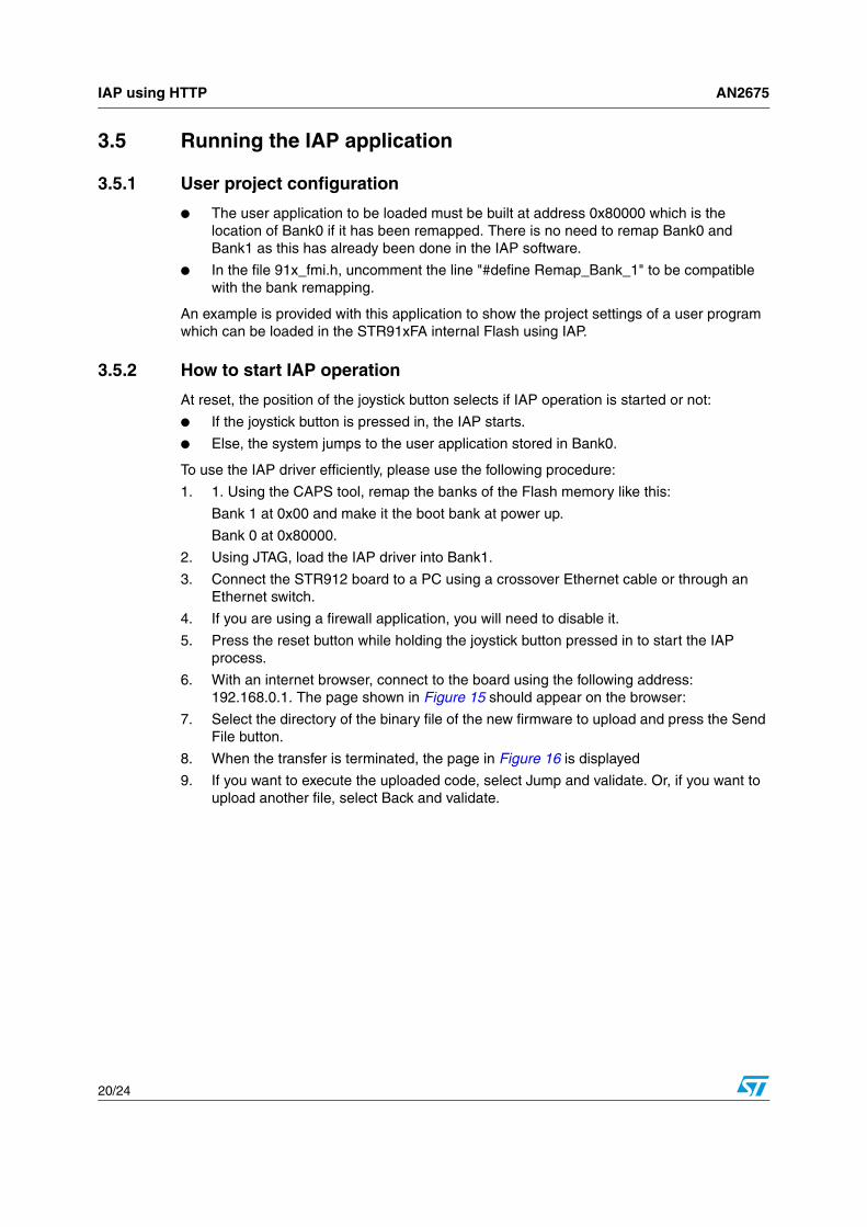
6. With an internet browser, connect to the board using the following address: 192.168.0.1. The page shown in Figure 15 should appear on the browser:
7. Select the directory of the binary file of the new firmware to upload and press the Send File button.
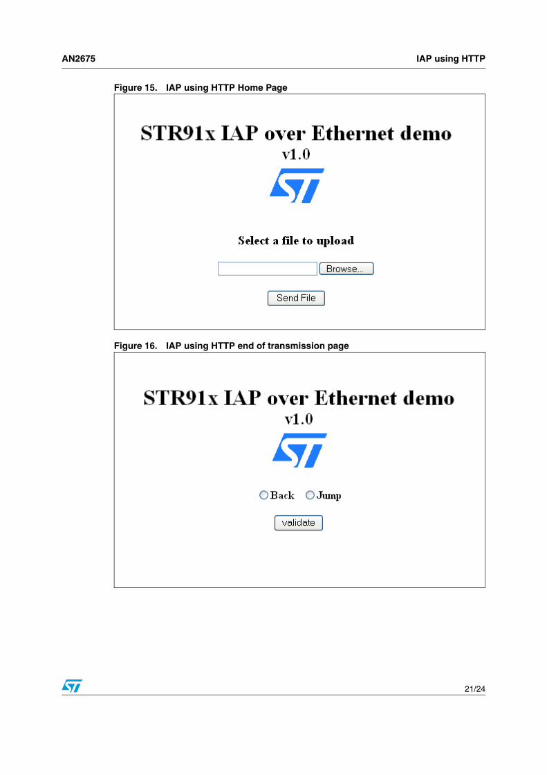
8. When the transfer is terminated, the page in Figure 16 is displayed
9. If you want to execute the uploaded code, select Jump and validate. Or, if you want to upload another file, select Back and validate.
AN2675 IAP using HTTP
21/24
Figure 15. IAP using HTTP Home Page
Figure 16. IAP using HTTP end of transmission page

IAP using HTTP AN2675
22/24
3.6 Driver descriptionThe IAP using HTTP application is a mini web server that offers possibility to upload files. Itis based on the uIP stack that manages all TCP/IP traffic. uIP is a free TCP/IP stackdesigned originally for 8-bit/16-bit microcontrollers. For more details about the uIP stackplease refer to: www.sics.se/~adam/uip/.
The Application Layer is controlled by functions included in the "httpd.c" file.
In addition, there are some configuration and control functions included in the file “util.c”, theENET FWLib folder, which is the driver of the STR91xFA ENET, and some files from theSTR91xFA Standard library.

AN2675 Revision history
23/24
4 Revision history
Table 4. Document revision history
Date Revision Changes
04-Feb-2008 1 Initial release.

AN2675
24/24
Please Read Carefully:
Information in this document is provided solely in connection with ST products. STMicroelectronics NV and its subsidiaries (“ST”) reserve theright to make changes, corrections, modifications or improvements, to this document, and the products and services described herein at anytime, without notice.
All ST products are sold pursuant to ST’s terms and conditions of sale.
Purchasers are solely responsible for the choice, selection and use of the ST products and services described herein, and ST assumes noliability whatsoever relating to the choice, selection or use of the ST products and services described herein.
No license, express or implied, by estoppel or otherwise, to any intellectual property rights is granted under this document. If any part of thisdocument refers to any third party products or services it shall not be deemed a license grant by ST for the use of such third party productsor services, or any intellectual property contained therein or considered as a warranty covering the use in any manner whatsoever of suchthird party products or services or any intellectual property contained therein.
UNLESS OTHERWISE SET FORTH IN ST’S TERMS AND CONDITIONS OF SALE ST DISCLAIMS ANY EXPRESS OR IMPLIEDWARRANTY WITH RESPECT TO THE USE AND/OR SALE OF ST PRODUCTS INCLUDING WITHOUT LIMITATION IMPLIEDWARRANTIES OF MERCHANTABILITY, FITNESS FOR A PARTICULAR PURPOSE (AND THEIR EQUIVALENTS UNDER THE LAWSOF ANY JURISDICTION), OR INFRINGEMENT OF ANY PATENT, COPYRIGHT OR OTHER INTELLECTUAL PROPERTY RIGHT.
UNLESS EXPRESSLY APPROVED IN WRITING BY AN AUTHORIZED ST REPRESENTATIVE, ST PRODUCTS ARE NOTRECOMMENDED, AUTHORIZED OR WARRANTED FOR USE IN MILITARY, AIR CRAFT, SPACE, LIFE SAVING, OR LIFE SUSTAININGAPPLICATIONS, NOR IN PRODUCTS OR SYSTEMS WHERE FAILURE OR MALFUNCTION MAY RESULT IN PERSONAL INJURY,DEATH, OR SEVERE PROPERTY OR ENVIRONMENTAL DAMAGE. ST PRODUCTS WHICH ARE NOT SPECIFIED AS "AUTOMOTIVEGRADE" MAY ONLY BE USED IN AUTOMOTIVE APPLICATIONS AT USER’S OWN RISK.
Resale of ST products with provisions different from the statements and/or technical features set forth in this document shall immediately voidany warranty granted by ST for the ST product or service described herein and shall not create or extend in any manner whatsoever, anyliability of ST.
ST and the ST logo are trademarks or registered trademarks of ST in various countries.
Information in this document supersedes and replaces all information previously supplied.
The ST logo is a registered trademark of STMicroelectronics. All other names are the property of their respective owners.
© 2008 STMicroelectronics - All rights reserved
STMicroelectronics group of companies
Australia - Belgium - Brazil - Canada - China - Czech Republic - Finland - France - Germany - Hong Kong - India - Israel - Italy - Japan - Malaysia - Malta - Morocco - Singapore - Spain - Sweden - Switzerland - United Kingdom - United States of America
www.st.com
![IAP antagonists sensitize murine osteosarcoma cells to ... · IAP activity within cells can be reduced by Smac/ Diablo, a natural IAP antagonist protein [14, 15]. A number of “IAP](https://static.fdocuments.in/doc/165x107/5c25d3f409d3f28d198c1460/iap-antagonists-sensitize-murine-osteosarcoma-cells-to-iap-activity-within.jpg)