Story of the TCUBED (T3) project (Bringing a T1 back to ...
15
Story of the TCUBED (T 3 ) project... (Bringing a T1 back to life) March 2010 Being a big Rush fan I always wanted a set of Taurus 1 bass synthesizer pedal’s but they were always out of reach…In the 90’s, the Bass player in my band had a set of T2’s that I played at our shows. I wanted my own Taurus pedals, so, in November of 2007, I tried to get a T2 and ended up getting a Moog Rogue off of eBay ($580USD). I de-gooed it, re-capped it, replaced the KB bushings and installed a Synhouse MIDIJack to allow MIDI triggering from a set of PK-5A MIDI Pedals….this kept me excited for a while but I still wanted a set of T1’s. Before the announcement of the reissue of the new Moog Taurus 3, to finally quench my thirst for the T1, I purchased a ‘scrap’ Moog Taurus 1 main-board on eBay ($300USD) from timevoyagemusic.com (Allen Brunelle) in April of 2008.
Transcript of Story of the TCUBED (T3) project (Bringing a T1 back to ...

Story of the TCUBED (T3) project... (Bringing a T1 back to life) March 2010
Being a big Rush fan I always wanted a set of Taurus 1 bass synthesizer pedal’s but they were always out
of reach…In the 90’s, the Bass player in my band had a set of T2’s that I played at our shows.
I wanted my own Taurus pedals, so, in November of 2007, I tried to get a T2 and ended up getting a
Moog Rogue off of eBay ($580USD).
I de-gooed it, re-capped it, replaced the KB bushings and installed a Synhouse MIDIJack to allow MIDI
triggering from a set of PK-5A MIDI Pedals….this kept me excited for a while but I still wanted a set of
T1’s.
Before the announcement of the reissue of the new Moog Taurus 3, to finally quench my thirst for the
T1, I purchased a ‘scrap’ Moog Taurus 1 main-board on eBay ($300USD) from timevoyagemusic.com
(Allen Brunelle) in April of 2008.
It was a board that had been sacrificed to repair other Taurus 1’s and was sold as-is. From the pictures of
the board it didn’t look like there were too many parts missing and I do like a good challenge. I banked on
my background in electronics engineering to take on this project when I envisioned a table-top unit with
the switches and sliders mounted on a sloped chassis with MIDI implementation. Originally, my plan was
to re-create the Taurus around this one component. I was thinking a rack-mount unit, but the main-board
was longer than 19 inches. When I received the main-board, I was pretty excited except for broken preset
slider handles, missing transistors, missing op amps, missing capacitors, a few holes in the PCB that
weren’t supposed to be there and a ‘scrap’ notation written in magic marker.
Here’s how I tackled the project…
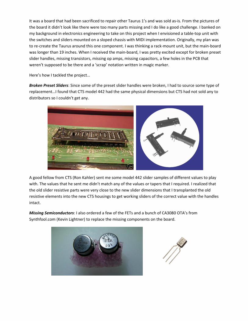
Broken Preset Sliders: Since some of the preset slider handles were broken, I had to source some type of
replacement…I found that CTS model 442 had the same physical dimensions but CTS had not sold any to
distributors so I couldn’t get any.
A good fellow from CTS (Ron Kahler) sent me some model 442 slider samples of different values to play
with. The values that he sent me didn’t match any of the values or tapers that I required. I realized that
the old slider resistive parts were very close to the new slider dimensions that I transplanted the old
resistive elements into the new CTS housings to get working sliders of the correct value with the handles
intact.
Missing Semiconductors: I also ordered a few of the FETs and a bunch of CA3080 OTA’s from
Synthfool.com (Kevin Lightner) to replace the missing components on the board.

T1 Power Supply: Since I only had the T1 main-board to work with, I had to build my own power supply.
Wanting to be as accurate as possible to the original power supply, I scanned the Power Supply PCB
layout from the T1 manual, I sourced all of the components and recreated the PCB and from scratch.
I purchased a Hammond 30 VAC centre-tapped Torroid transformer as opposed to an open-frame style
for the power transformer.
The Voltage Regulator, (SG1468N), was the hardest to find. Luckily, a local parts distributor had one
MC1468L in new old stock. Works like a charm. This power supply provides +15, -15 and +5 VDC to the T1
Main-board.
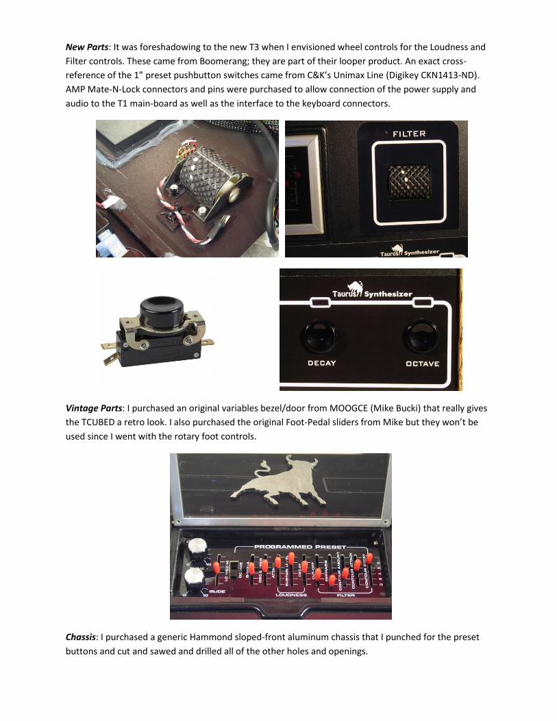
New Parts: It was foreshadowing to the new T3 when I envisioned wheel controls for the Loudness and
Filter controls. These came from Boomerang; they are part of their looper product. An exact cross-
reference of the 1” preset pushbutton switches came from C&K’s Unimax Line (Digikey CKN1413-ND).
AMP Mate-N-Lock connectors and pins were purchased to allow connection of the power supply and
audio to the T1 main-board as well as the interface to the keyboard connectors.
Vintage Parts: I purchased an original variables bezel/door from MOOGCE (Mike Bucki) that really gives
the TCUBED a retro look. I also purchased the original Foot-Pedal sliders from Mike but they won’t be
used since I went with the rotary foot controls.
Chassis: I purchased a generic Hammond sloped-front aluminum chassis that I punched for the preset
buttons and cut and sawed and drilled all of the other holes and openings.
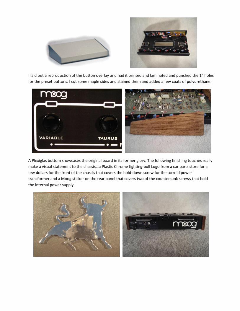
I laid out a reproduction of the button overlay and had it printed and laminated and punched the 1” holes
for the preset buttons. I cut some maple sides and stained them and added a few coats of polyurethane.
A Plexiglas bottom showcases the original board in its former glory. The following finishing touches really
make a visual statement to the chassis…a Plastic Chrome fighting-bull Logo from a car parts store for a
few dollars for the front of the chassis that covers the hold-down screw for the torroid power
transformer and a Moog sticker on the rear panel that covers two of the countersunk screws that hold
the internal power supply.
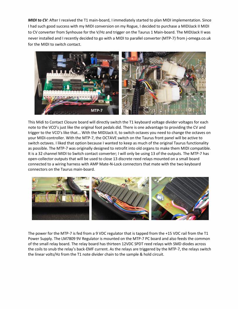
MIDI to CV: After I received the T1 main-board, I immediately started to plan MIDI implementation. Since
I had such good success with my MIDI conversion on my Rogue, I decided to purchase a MIDIJack II MIDI
to CV converter from Synhouse for the V/Hz and trigger on the Taurus 1 Main-board. The MIDIJack II was
never installed and I recently decided to go with a MIDI to parallel converter (MTP-7) from j-omega.co.uk
for the MIDI to switch contact.
This Midi to Contact Closure board will directly switch the T1 keyboard voltage divider voltages for each note to the VCO’s just like the original foot pedals did. There is one advantage to providing the CV and trigger to the VCO’s like that... With the MIDIJack II, to switch octaves you need to change the octaves on your MIDI-controller. With the MTP-7, the OCTAVE switch on the Taurus front panel will be active to switch octaves. I liked that option because I wanted to keep as much of the original Taurus functionality as possible. The MTP-7 was originally designed to retrofit into old organs to make them MIDI compatible. It is a 32 channel MIDI to Switch contact converter; I will only be using 13 of the outputs. The MTP-7 has open-collector outputs that will be used to close 13 discrete reed relays mounted on a small board connected to a wiring harness with AMP Mate-N-Lock connectors that mate with the two keyboard connectors on the Taurus main-board.
The power for the MTP-7 is fed from a 9 VDC regulator that is tapped from the +15 VDC rail from the T1 Power Supply. The LM7809 9V Regulator is mounted on the MTP-7 PC board and also feeds the common of the small relay board. The relay board has thirteen 12VDC SPDT reed relays with SMD diodes across the coils to snub the relay’s back-EMF current. As the relays are triggered by the MTP-7, the relays switch the linear volts/Hz from the T1 note divider chain to the sample & hold circuit.
MTP-7
Troubleshooting the T1 Main-board
The following outline of what was done seems like just a small amount of time, but, the actual time spent
probing the board with a scope and measuring voltages, as well as analyzing the schematic and board
layout, easily adds up to over 20 Hours.
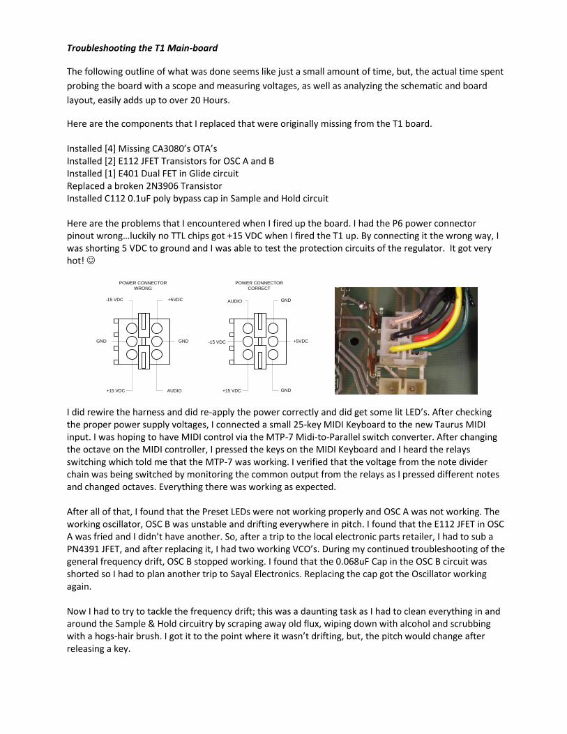
Here are the components that I replaced that were originally missing from the T1 board. Installed [4] Missing CA3080’s OTA’s Installed [2] E112 JFET Transistors for OSC A and B Installed [1] E401 Dual FET in Glide circuit Replaced a broken 2N3906 Transistor Installed C112 0.1uF poly bypass cap in Sample and Hold circuit Here are the problems that I encountered when I fired up the board. I had the P6 power connector pinout wrong…luckily no TTL chips got +15 VDC when I fired the T1 up. By connecting it the wrong way, I was shorting 5 VDC to ground and I was able to test the protection circuits of the regulator. It got very hot!
I did rewire the harness and did re-apply the power correctly and did get some lit LED’s. After checking the proper power supply voltages, I connected a small 25-key MIDI Keyboard to the new Taurus MIDI input. I was hoping to have MIDI control via the MTP-7 Midi-to-Parallel switch converter. After changing the octave on the MIDI controller, I pressed the keys on the MIDI Keyboard and I heard the relays switching which told me that the MTP-7 was working. I verified that the voltage from the note divider chain was being switched by monitoring the common output from the relays as I pressed different notes and changed octaves. Everything there was working as expected. After all of that, I found that the Preset LEDs were not working properly and OSC A was not working. The working oscillator, OSC B was unstable and drifting everywhere in pitch. I found that the E112 JFET in OSC A was fried and I didn’t have another. So, after a trip to the local electronic parts retailer, I had to sub a PN4391 JFET, and after replacing it, I had two working VCO’s. During my continued troubleshooting of the general frequency drift, OSC B stopped working. I found that the 0.068uF Cap in the OSC B circuit was shorted so I had to plan another trip to Sayal Electronics. Replacing the cap got the Oscillator working again. Now I had to try to tackle the frequency drift; this was a daunting task as I had to clean everything in and around the Sample & Hold circuitry by scraping away old flux, wiping down with alcohol and scrubbing with a hogs-hair brush. I got it to the point where it wasn’t drifting, but, the pitch would change after releasing a key.
GNDAUDIO
POWER CONNECTOR
CORRECT
GND
+5VDC
+15 VDC
-15 VDCGND
AUDIO
POWER CONNECTOR
WRONG
GND
+5VDC
+15 VDC
-15 VDC

At this point I decided to do a full alignment/ tuning. There were no problems with the alignment as I had a scope and a strobe tuner to adjust the proper frequencies and my ears to zero beat the oscillators. After the alignment the Taurus came to life! All of the sounds were there! This was all well and good, but, I needed to tackle the slight pitch change when releasing a key. I noticed that I could stabilize the pitch change when I pressed on the circuit board in the area around the sample and hold circuit. I also pulled up on C112 and could stabilize the VCO that way as well. I decided to replace C112 and everything went haywire. The presets were distorting and the VCO’s were ramping up to a high frequency; what a mess. I did more cleaning and scraping to no avail. On the circuit board, capacitor C112 is mounted on the top side of the PCB and soldered on the back side. This assumes that solder will wick from the bottom of the PCB to the signal traces underneath the capacitor on the top side. A simple ohm check proved that one end of the cap was not grounded. I pulled C112 and did something weird. I soldered the cap on the back side which ensured a good connection by ensuring good soldering on top and allowing cleaning of all of the excess flux that de-stabilizes the Sample and Hold Circuit.
After putting it all back together, I had a stable Taurus! There was no need for a re-alignment as the pitch change problem that I corrected had no effect on the alignment. In order to be completely happy, I had to repair the logic for the Preset LED’s. When the LED for the BASS Preset was connected, it killed the sound and the LED would not stay on. I left the Bass LED disconnected until I found that two of the 7410’s had no GND potential on pin 7. I found that a decoupling capacitor lead, that is supposed to bridge ground from the top to the bottom of the board to feed the two 7410’s, had a cold solder joint. I reflowed the joint and everything started working properly with the Preset LED’s. One more thing was bothering me… the Glide switch didn’t seem to be de-bounced properly. A single press wouldn’t turn the Glide on/off, I would have to press the Glide switch quickly a few times to activate and de-activate the Glide. Knowing that something like this would drive the perfectionist in me crazy, I went ahead and tried to fix the switch problem. I logic probed the circuitry around IC909 and IC910 and found clean pulses until I got to the output of IC910. This is where the intermittent pulses were starting. Not much to this part of the circuit beside the Flip-Flop, capacitor, LED and resistor. On a hunch, I paralleled the 0.01uF capacitor with a 100uF electrolytic. This was a crowbar solution that fixed the problem completely! I thought to myself… “I think I’m Finished”… and I was! It was around 11:00PM, close to my bed time, but, I spent the next 10 minutes through a Bass Amplifier auditioning the sounds and adjusting the beat frequencies.

The following morning was spent connecting my Roland PK-5A MIDI Pedals, to control the T1 via MIDI,
and connecting the audio out to a small PA. Due to the common Voltage Divider resistor chain, this
sucker has no warm up time and is always in tune and stays in tune. I couldn’t believe it… I finally had a
Taurus Synthesizer! And it’s a custom unit with MIDI functionality.
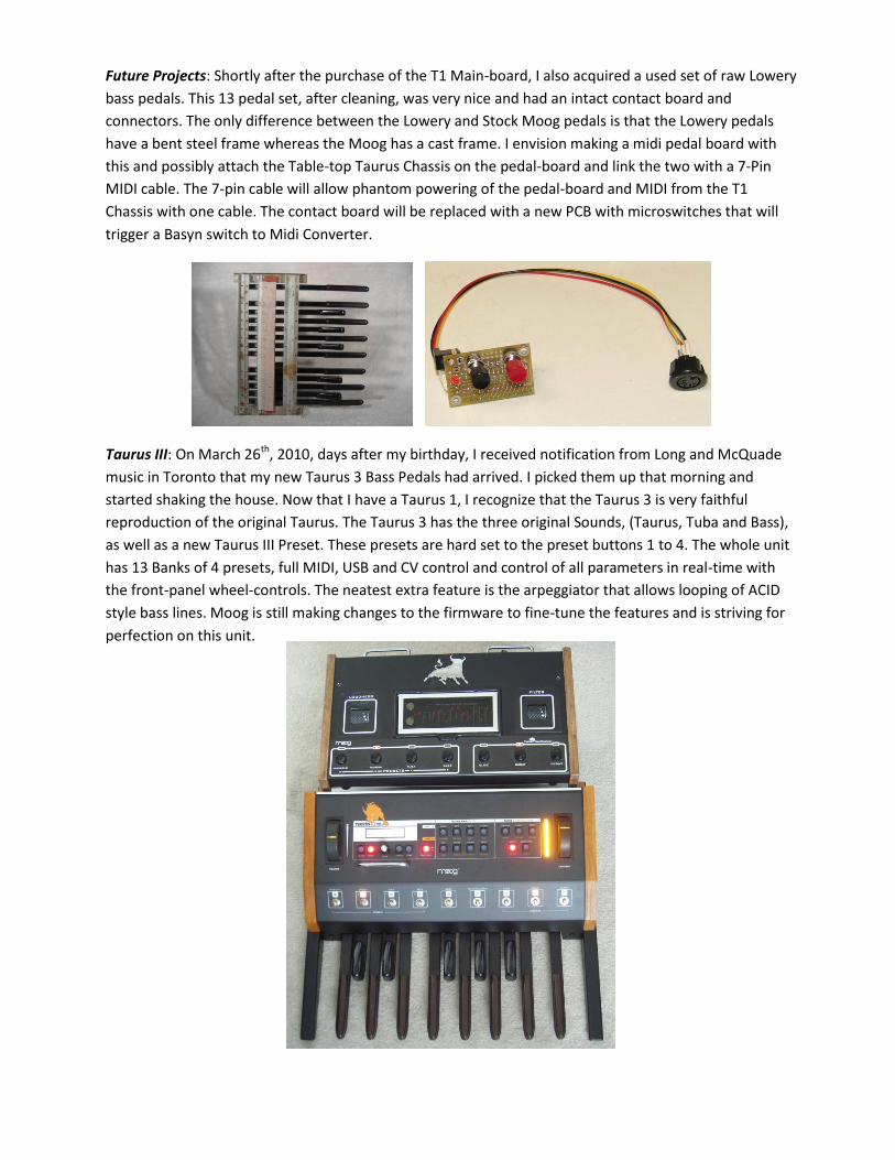
Future Projects: Shortly after the purchase of the T1 Main-board, I also acquired a used set of raw Lowery
bass pedals. This 13 pedal set, after cleaning, was very nice and had an intact contact board and
connectors. The only difference between the Lowery and Stock Moog pedals is that the Lowery pedals
have a bent steel frame whereas the Moog has a cast frame. I envision making a midi pedal board with
this and possibly attach the Table-top Taurus Chassis on the pedal-board and link the two with a 7-Pin
MIDI cable. The 7-pin cable will allow phantom powering of the pedal-board and MIDI from the T1
Chassis with one cable. The contact board will be replaced with a new PCB with microswitches that will
trigger a Basyn switch to Midi Converter.
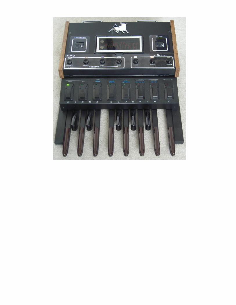
Taurus III: On March 26th, 2010, days after my birthday, I received notification from Long and McQuade
music in Toronto that my new Taurus 3 Bass Pedals had arrived. I picked them up that morning and
started shaking the house. Now that I have a Taurus 1, I recognize that the Taurus 3 is very faithful
reproduction of the original Taurus. The Taurus 3 has the three original Sounds, (Taurus, Tuba and Bass),
as well as a new Taurus III Preset. These presets are hard set to the preset buttons 1 to 4. The whole unit
has 13 Banks of 4 presets, full MIDI, USB and CV control and control of all parameters in real-time with
the front-panel wheel-controls. The neatest extra feature is the arpeggiator that allows looping of ACID
style bass lines. Moog is still making changes to the firmware to fine-tune the features and is striving for
perfection on this unit.

An interesting story about the T1 Note Divider Chain…
When I first received my Taurus I had visions of the possibility of using my Lowery foot pedals to trigger
the Taurus main-board. I understood how important the Note Divider Chain of Resistors was to create
the proper exponential voltages for the Volt/Hz oscillators. The Note Divider Chain is a custom resistor
pack with 13 close tolerance resistors designed and manufactured by CTS.
I tried to measure the actual resistances on the chip and it looked like my Resistor network was partially
damaged, and I would have to calculate the missing sections to create the proper voltages
Now I had to find the actual resistances of all of the resistors (including the damaged ones).
In the manual, the resistors are based on a progression…this was very cryptic. Amos at Moog gave
me some insight on the . He mentioned that the calculation is based on = 1.059463094.
This was the number that was going to help me. It helped me find the exact Tap Voltages for each note
and I calculated it like this…
Since I knew that the C1 Tap should be at 5V, I calculated all of the subsequent tap voltages using the
twelfth root of 2, [ ], [1.059463094]
C1 = 5V,
B = C x 1.059463094 = 5 x 1.059463094 = 5.2973V,
A# = B x 1.059463094 = 5.2973V x 1.059463094 = 5.6123V and so on to 10 V at the C2 tap.
The measurements that I made on the resistors in the top half of the chain, (including the averaged
guesses of the damaged resistors), came to 20897 Ohms…I rounded that off to 20900 Ohms. That would
mean that the bottom half of the chain would have to be 20900 Ohms as well…the actual CTS chip
resistance for the bottom resistor is about 20450 Ohms. That makes sense because there is a 1000 Ohm
"Scale" Trimmer for fine-tuning to the 20900 Ohms. So the Total resistance in the Chain can be assumed
to be 41800 Ohms.
Note 2' 4' 8' 16'
C2 10 5 2.5 1.25
C# 9.4387 4.7194 2.3597 1.1798
D 8.9090 4.4545 2.2272 1.1136
D# 8.4090 4.2045 2.1022 1.0511
E 7.9370 3.9685 1.9843 0.9921
F 7.4915 3.7458 1.8729 0.9364
F# 7.0711 3.5355 1.7678 0.8839
G 6.6742 3.3371 1.6685 0.8343
G# 6.2996 3.1498 1.5749 0.7875
A 5.9460 2.9730 1.4865 0.7433
A# 5.6123 2.8062 1.4031 0.7015
B 5.2973 2.6487 1.3243 0.6622
C1 5 2.5 1.25 0.625
OCTAVE
RESISTOR LADDER TAP VOLTAGES
12 2
12 2 12 2
12 2

Now that we have the Top Divider Voltage and the Total Chain Resistance, we can calculate the Total
Chain Current.
Chain Current = (Top Divider Voltage) divided by (Total Divider Resistance)
= 10 / 41800
= 0.000239234 Amps
Then, I calculated the discrete resistance values using ohms law again. I used the following formula: Using the F Note as an example…
"Total required resistance" to F = (Tap voltage) divided by the (full chain current)
= 7.4915 / 0.000239234
= 31314.62 Ohms
Now that I had the Resistance values to each Note’s TAP, to get the discrete resistor value, I took the
"total required resistance" and subtracted from the previous resistance value to get the difference.
Using the F Note Resistor as an example…
Discrete F Resistor Value = Resistance to F TAP - Resistance to F# TAP
= 31314.62 - 29557.06
= 1757.55 Ohms
I repeated this in the above Spreadsheet to get all of values of the discrete resistors. My calculations
were very close to the actual ohm meter measured resistances so I knew that I had succeeded.
After all of the useful and time consuming calculations, I found that the CTS Network was not actually
damaged...there was a cold-solder joint on the circuit board.
C 10.0000 41800.00 2346.05 Damaged 1 13-14
C# 9.4387 39453.95 2214.38 2211 2 12-13
D 8.9090 37239.57 2090.10 2091 3 11-12
D# 8.4090 35149.47 1972.79 1974 4 10-11
E 7.9370 33176.68 1862.06 1862 5 9-10
F 7.4915 0.000239234 31314.62 1757.55 1756 6 8-9
F# 7.0711 29557.06 1658.91 1657 7 7-8
G 6.6742 27898.15 1565.80 1565 8 6-7
G# 6.2996 26332.35 1477.92 1477 9 5-6
A 5.9460 24854.43 1394.97 1395 10 4-5
A# 5.6123 23459.46 1316.68 1320 11 3-4
R-Chain - Top Half B 5.2973 22142.78 1242.78 1243 12 2-3
20900 C 5.0000 20900.00 20900.00 20460 13 1-2
20900
R-Chain - Bottom Half 2 Root 12 1.059463094
Discrete
Resistors [ohms]
[= Resistance to
Tap - Lower Tap
Resistance]
Full Chain
Current [A]
[=Top Voltage /
R Chain
top+bottom]
CTS Pin
Numbers
Resistor
Number
Voltage [V]
[=Previous
Voltage x
1.059463]NOTEResistor Chain [Ohms]
Actual Ohm
Meter
Measured
[ohms]
Resistance To
Tap [ohms]
[=Tap Voltage
/ Full Chain
Current]

TAURUS I MIDI IMPLEMENTATION
BLUE
GND GLIDE C2
B A A#C1C#D
F D#
E
F#GG#
BROWNREDORANGE
YELLOW
GREEN
VIOLETGREYWHITE
BROWN/ST PINKGREEN/ST
BLUE/STShielded
Wire
KEYBOARD CONNECTORS
RELAY BOARD
SCALE TRIM
IC105
FROM
OCTAVE
DIVIDER
CHAIN
NOTE DIVIDER CHAIN
[CUSTOM CTS
RESISTOR NETWORK]
R118 to R129 Total
Resistance is 20900
Ohms
1000 W
2' = 10VDC
4' = 5VDC
8' = 2.5VDC
16' = 1.25VDC
G
F#
F
E
D#
C2
B
A#
A
G#
D
C1
C#
TO GLIDE AND
TRIGGER
CIRCUIT
MTP-7
MIDI IN
+15 VDC7809
+9
+9
+9
+9
+9
+9
+9
+9
+9
+9
+9
+9
+9
1
2
3
4
5
6
7
8
9
10
11
12
13
1757.55 W
1658.91 W
1565.80 W
1477.92 W
1394.97 W
2346.05 W
2214.38 W
2090.10 W
1972.79 W
1862.06 W
1316.68 W
1242.78 W
20450 W
10.000
9.438
8.909
8.409
7.937
7.492
7.071
6.674
6.299
5.946
5.612
5.297
5.000
TAP
VOLTAGE
MID
I T
O P
AR
AL
LE
L
PINK
BLUE/ST
GREEN/ST
BROWN
RED
ORANGE
YELLOW
GREEN
BLUE
VIOLET
GREY
WHITE
BROWN/ST
RED/ST
NO NC
R123
R124
R125
R126
R127
R118
R119
R120
R121
R122
R128
R129
R130
1
2
3
4
5
6
7
8
9
10
11
12
13
14

This Article is Slash Approved