Samuel Danso, Eric Atwell, Owen Johnson, Augustinus H - icame

Marco RV Resort
Stormwater Pump Station (PS B)
Prepared for: Atwell, LLC Two Towne Square, Suite 700 Southfield, MI 48076
Prepared by: Stantec
MARCO RV RESORT
Table of Contents
LIST OF EXHIBITS ............................................................................................................................ I
1.0 INTRODUCTION ............................................................................................................. 1.1
2.0 SITE VISIT ........................................................................................................................ 2.1 2.1 PUMP STATION B (EXISTING CONDTIONS) ..................................................................... 2.1
3.0 DESIGN CRITERIA .......................................................................................................... 3.1 3.1 PROPOSED FACILITIES ....................................................................................................... 3.1 3.2 DESIGN FLOW .................................................................................................................... 3.2 3.3 PUMP SELECTION .............................................................................................................. 3.2 3.4 FUEL CONSUMPTION ........................................................................................................ 3.2 3.5 WETWELL DESIGN ................................................................................................................. 1 3.6 PUMP REMOVAL .................................................................................................................. 1 3.7 MINIMUM ELEVATION REQUIREMENTS .............................................................................. 2 3.8 OUTFALL DESIGN .................................................................................................................. 2
4.0 ELECTRICAL ...................................................................................................................... 2 4.1 SERVICE ................................................................................................................................. 2 4.2 DISTRIBUTION......................................................................................................................... 2 4.3 PUMP CONTROL PANEL ...................................................................................................... 3

MARCO RV RESORT
i
List of Exhibits
1. SITE MAP
2. HYDRAULIC CALCULATIONS
2.1 DIESEL SUCTION PUMP CALCULATIONS
2.2 ELECTRIC PUMP CALCULCATIONS
3. PUMP DATA TABLES
4. CYCLE TIME CALCULATIONS
4.1 DETENTION STORAGE CALCULATION
5. PUMP MANUFACTURER INFORMATION
5.1 PUMP MANUFACTURER (DIESEL)
5.2 PUMP MANUFACTURER (ELECTRIC)
5.3 DIESEL FUEL CONSUMPTION CALCULATIONS
6. BUOYANCY CALCULATIONS
7. FEMA FLOOD MAP
8. PUMP REMOVAL TRUCK
MARCO RV RESORT
bv \\us1521-f01\workgroup\1773\active\215614127\reports\permit\report_marco park rv naples_permit.docx 3.1
1.0 INTRODUCTION
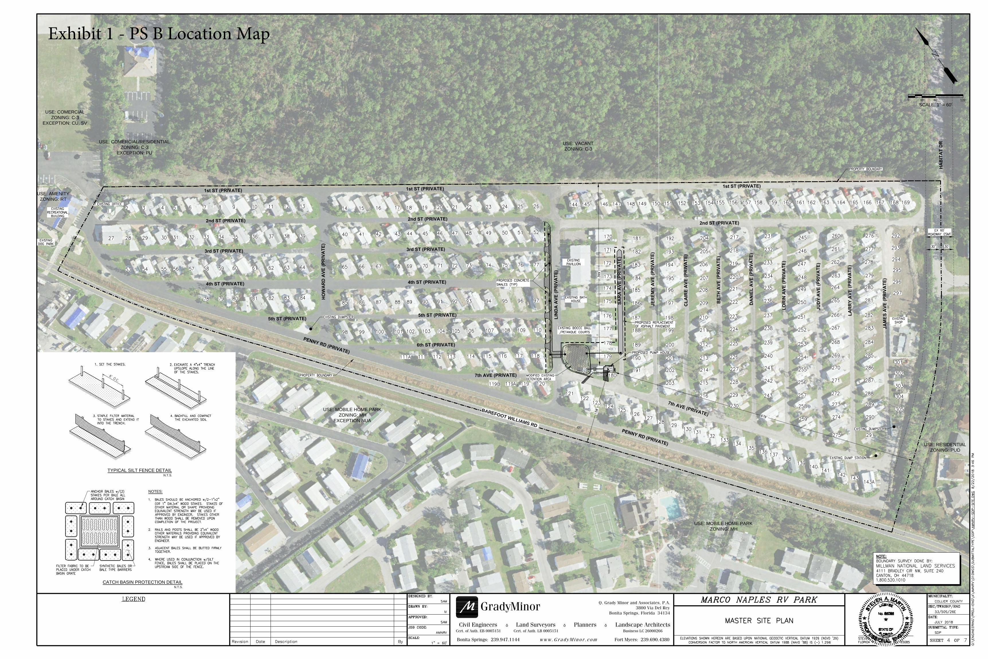
Stantec was contracted to provide engineering services for the design of a stormwater pump station at the Marco RV Resort. The pump station upgrades will be part of a neighborhood wide drainage improvement plan. This report will include the design criteria and proposed elements for Pump Station B located on the north corner of the 7th Avenue/Sara Avenue intersection.
2.0 SITE VISIT
On August 24, 2017 Stantec visited the project site to evaluate the existing conditions and assess the existing pump stations. The existing drainage system relies on a piped conveyance system, drainage ponds, and (2) discharge pump stations which outfall into Barefoot Williams Road’s roadside swale. The stations are identified as Pump Station A, and Pump Station B (See Exhibit 1 – Location Map).
2.1 PUMP STATION B (EXISTING CONDTIONS)
Pump station B is equipped with a gasoline operated pump, and an automated electric submersible pump. This station has a suction side located inside a drainage pond and discharges into the roadside swale (via an existing buried discharge pipe). The electric power is serviced by a nearby 120/240V single phase panelboard.
The maintenance staff provided Stantec with history of the drainage issues, performance of the existing stations, and future upgrade considerations. This information was used to evaluate potential design concepts. The concepts were to consider the potential maintenance staff upgrades, the requested capacity of each pump station, the electrical power availability, and the scope of the original project.
3.0 DESIGN CRITERIA
3.1 PROPOSED FACILITIES
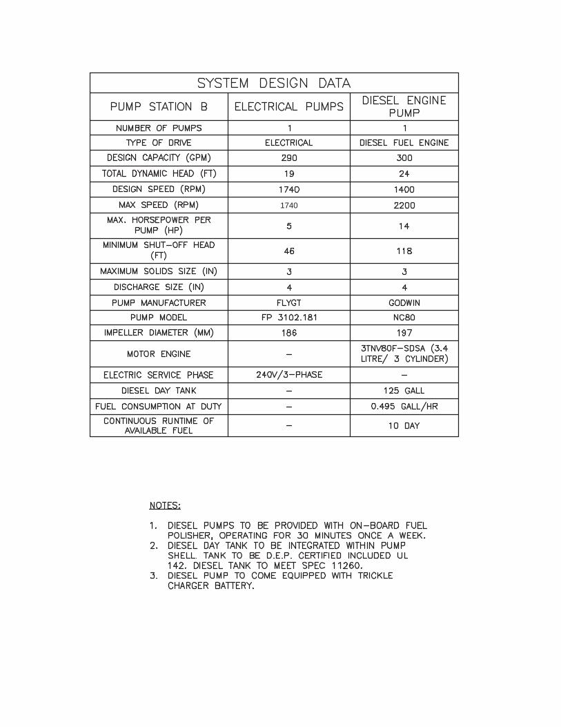
Pump Station B: • New 6-foot (inside diameter) wet well • 4-inch and 6-inch piping • (1) New Godwin NC80 Dri-Prime Pumps with 3TNV80F-SDSA, 3-Cylinder Engine
o Integrated 125-gallon UL 142 Diesel Fuel Day tank • (1) New Flygt FP 3102 LT 3 ~494 Electric Pump with Cutting Impellers • New concrete structure with trash rack • New concrete energy dissipater device
MARCO RV RESORT
bv \\us1521-f01\workgroup\1773\active\215614127\reports\permit\report_marco park rv naples_permit.docx 3.2
3.2 DESIGN FLOW
PS A and PS B both discharge to Barefoot Williams Road’s roadside swale which has an allowable capacity discharge of 6 cfs (2,700 gpm) set by Collier County. This discharge rate was used to determine the operating points for each pump station. PS A requires greater flood relief requiring larger pumps, this station will be designed in the future with an approximate rate flow of at least 2,000 gpm. PS B discharges from a small pond, therefore, a design rate of 300 gpm was considered.
3.3 PUMP SELECTION
Pump Station B was designed to meet a design discharge rate of 300 gpm. The piping configuration of 4-inches provides a velocity of 7.66 ft/s and connecting to an existing 6-inch force main with a calculated velocity of 3.4 ft/s.
Pump station B has a 120/240V service nearby which allows for an electric pump for primary and an engine pump for backup.
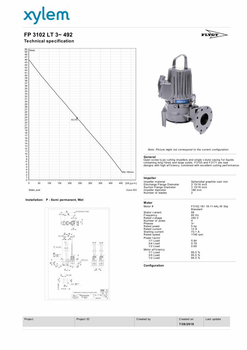
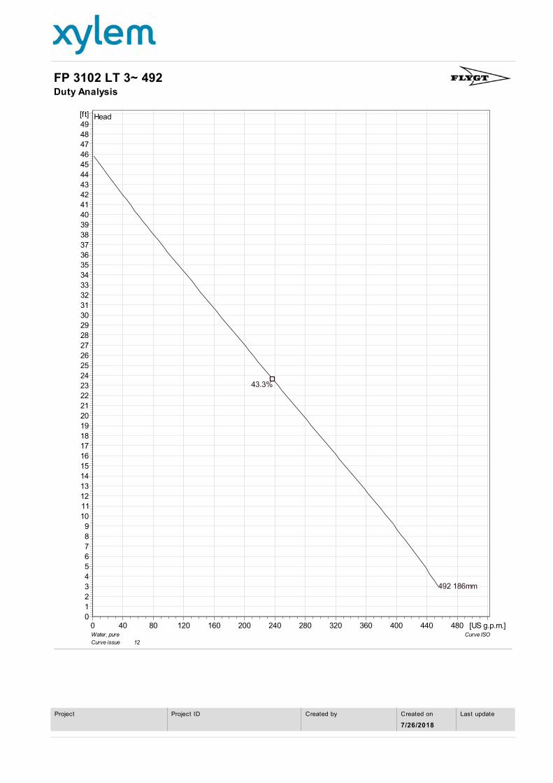
Primary pump – PS B will run with an electric pump as a primary option. The Flygt FP 3102 LT3 model has been selected for this application. This pump is rated at 5HP, 240V, 1740 rpm, and 3-phases. The pump is equipped with 186 mm impellers and open screw type cutters installed in its volute to help chop down debris. Its design operating point is 290 gpm at 90-ft of TDH, see Exhibit 2.2 – Hydraulic Calcs (Electric).
The electric pump will be serviced by a nearby 120/240V service.
Backup pump – For emergency scenarios, including power outage, a diesel fuel pump has been selected. The Godwin NC80 Di-Prime with 213mm impellers and 9 HP running at 1,400 rpm, or equal will meet the operating design point at 300 gpm with 24-ft of TDH, see Exhibit 2.1 – Hydraulic Calcs (Diesel). The engine for this pump will be a 3-Cylinder/3.4-Litre Yanmar Diesel Fuel Engine, model number 3TNV80F.
A pump data table has been included to summarize the pump characteristics, See Exhibit 3 – Pump Data Table.
3.4 FUEL CONSUMPTION
The Godwin diesel pump will have an integrated diesel fuel 125-gallon tank. At an operating point of 300 gpm, the Godwin diesel pump consumes fuel at a rate of 0.495 gal/hr; a total of 119-gallons is consumed when considering 10-days of continuous run time. The design includes one (1) 125-gallon tank which stores fuel for 10 consecutive days, an equivalent of five (5) 2-day storms, in case of power outage. See Exhibit 5.2 – Fuel Consumption Calculations.
3.5 WETWELL DESIGN
Following the established criteria for sizing the wet well, considering 50% of the the upstream storage capacity at the dry-detention pond, and setting the High Water Level (HWL) and Low Water Level (LWL) (Start Pump and Pumps-Off Levels, respectively), the design pump rate of results in a required operating depth of 1-feet. This operation keeps the pump cycle time to > or equal to 10 minutes for PS B. See Exhibit 4 – Cycle Time Calculations
In setting LWL, it was considered desirable that it be kept as high as possible in order to provide allowable submergence and provide the pump suction with the highest NPSH possible. The October Water Table was also considered to avoid an excessive groundwater drawdown conditions; this allows the LWL to be set at (+) 3.50. Likewise, the HWL is set at elevation (+) 4.50, this allows the pumps to begin pumping before the dry-detention pond overflows and maintains an operating depth of 1-feet.
The ‘ALL PUMPS OFF’ level is set at (+) 3.50 for PS B, this maximizes the NPSH available and provides enough NPSH for the selected pumps. See Exhibit 2.1 – Hydraulic Calculations (Diesel).
The diesel fuel pump is setup to turn on at elevation (+)5.00. This will occur when the electric pump is overwhelmed or not functioning, or when there is power failure.
The pump station structure was evaluated for flotation. Buoyancy forces were evaluated to determine the concrete wall thickness and bottom slab. The wet well structure for PS B will have 8-inch walls and a 1-foot thick bottom slab in order to overcome buoyant forces with a minimum safety factor of 1.10, the top slab was not included in the buoyancy calculations. See Exhibit 6 – Buoyancy Calculations.
3.6 PUMP REMOVAL
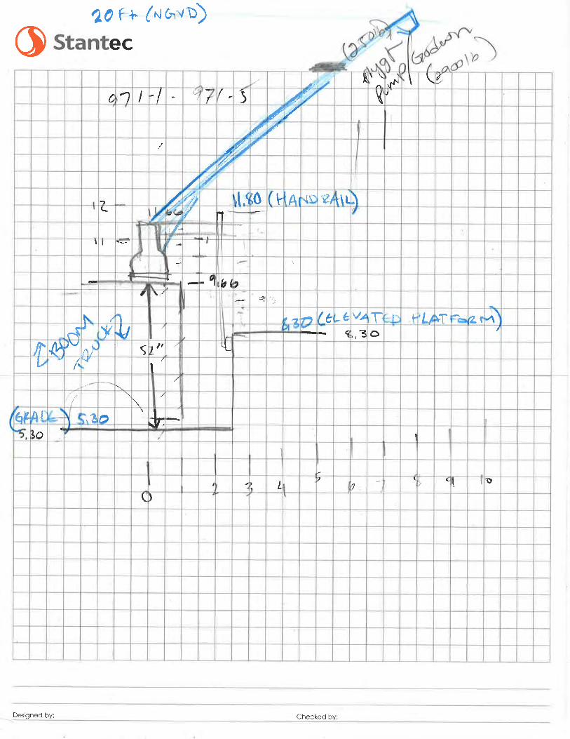
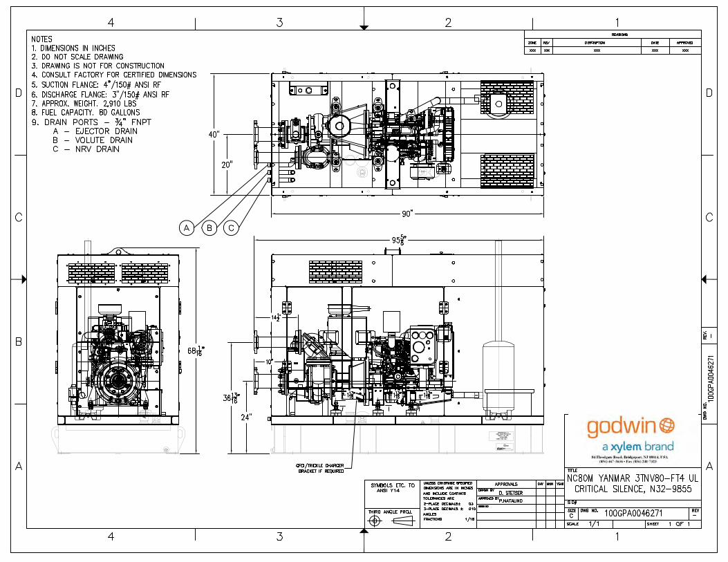
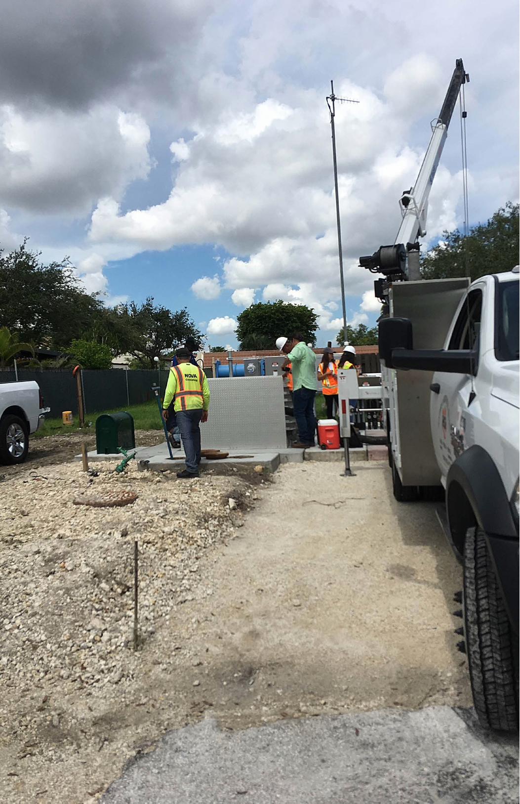
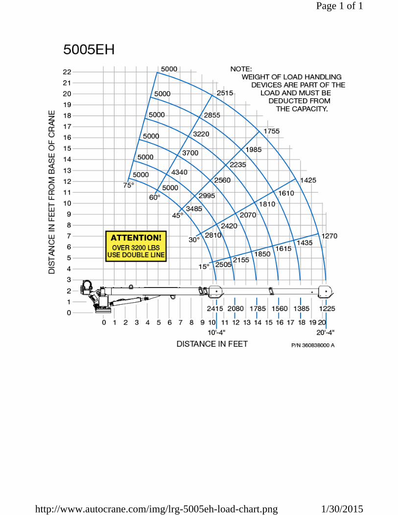
In order to facilitate the maintenance of the Flygt F3102 electrical pump, the top slab of the wet well is equipped with a 36”x36” access hatch to allow for its removal. The Godwin NC80 Di-Prime diesel pump sits outside the wet well on a concrete slab. The Flygt pump has a weight of 215 lbs, while the Godwin pump has a weight of 2,910 lbs, see Exhibit 5 – Pump Manufacturer. The proposed design includes a 10-foot wide gravel driveway for truck access. A typical crane truck used to remove submersible pumps typically have a loading capacity of 5,000 lbs, depending on the radius of the lift-arm. Both the electrical and diesel pump were placed in locations that will facilitate their removal during maintenance. The Flygt pump is 7-ft away from gravel driveway and about a 9-foot vertical distance from the lifting hook of the Flygt pump, a typical crane truck has sufficient capacity to remove the electric pump, see Exhibit 8 – Pump Removal.
The diesel pump will likely be installed by a regular crane due to its weight. Since the pump is skid mounted, maintenance work will be done on the platform. If the pump is ever needed to be removed a regular crane will need to be used.
3.7 MINIMUM ELEVATION REQUIREMENTS
The design elevation for the wet well structure, and concrete pad was designed to comply with the minimum flood criteria established in Chapter 11C, Florida Building Code and Chapter 62-604, FAC. Pump Station B lies within an AE zone with a Base Flood Elevation of 7.00 ft (NAVD 88), as per FEMA Community Number 120067, Panel Number 0604, Suffix H, Map No. 12021C0604H. Therefore, the minimum elevation criteria is BFE plus 1 foot of freeboard, the minimum elevation is 9.3 ft. Flood map elevations are based on the North American Vertical Datum of 1988 (NAVD 88) to convert to National Geodetic Vertical Datum of 1929 (NGVD 29), a factor of 1.26 ft is added to 7.00 ft, providing a BFE elevation of 8.3 ft (NGVD 29). Proposed electrical equipment and the diesel fuel tank are all installed with 1-ft of free board, clearing a minimum elevation of 9.30 (NGVD 29).
3.8 OUTFALL DESIGN
To reduce velocities at the outfall’s discharge point an energy dissipator structure is to be installed at the outfall location for PS B. The structure is designed to take the impact of the force main’s velocity and greatly reduce the discharge velocity into the roadside swale.
4.0 ELECTRICAL
4.1 SERVICE
The station will have a new, independent 120/240V single phase service. The service will be supplied by a nearby pole mounted transformer. The meter will be located on a new electrical equipment rack on the new elevated concrete pad.
4.2 DISTRIBUTION
The power will be distributed from a new service entrance rated panelboard, housed in a NEMA 4X stainless steel enclosure. This panelboard will be the source of power for all electrical equipment associated with the pump station. The main panelboard will include 3 breakers to feed the pump control panel, a GFCI convenience receptacle (to be mounted below the panelboard), and the diesel pump skid. The diesel pump skid, will include a load center that will distribute power to all electrical equipment that is mounted to the diesel pump skid (battery charger, fuel polisher, etc.). All electrical equipment will be installed in weatherproof stainless-steel enclosures. Exposed conduit will be rigid aluminum, underground conduit shall be PVC.
4.3 PUMP CONTROL PANEL
The pump control panel will be supplied by the pump manufacturer. It will include all the equipment necessary to start/stop the electric pump and provide visual alarm (alarm light) for high-high water level and low-low water level conditions. The control panel will include a Hand-Off-Auto switch to operate the pump manually, or automatically. In automatic control, the electric pump will be controlled using float switches (Low-Low Alarm, Stop Float, Start Float, High-High Alarm). The electric pump will be used for the primary means of draining the wet well. Therefore, the pump start float will be set lower than the diesel pump control floats. All buttons, switches, and breakers will be mounted to a dead-front panel, that sits behind the control panel outer door. The outer door will be lockable to prevent unauthorized tampering with the controls.
The pump control panel will require a 120/240V single phase power source but will output 3-phase power to the electrical pump. Conversion of power from single phase to 3-phase will be performed by a Variable Frequency Drive (VFD), mounted inside the control panel. The VFD will allow the pumps to be controlled at user adjustable speeds. The VFD will be set to operate the electric pump at full speed by default.
A junction box will be installed below the control panel. This junction box will house terminals for easy disconnect of the pumps and wet well instrumentation. The conduits between the junction box and control panel will be sealed to prevent gasses and moisture from traveling form the wet well, into the control panel enclosure.
4.4 DIESEL PUMP CONTROL
The diesel pump will be controlled completely independent from the electric pump. The diesel pump will be controlled using a controller provided by the diesel pump manufacturer. This controller will be mounted in the diesel pump skid. The controller will use independent floats, supplied by the pump manufacturer to start and stop the pump. These floats will be mounted higher than the floats used to control the electric pump, so the diesel pump will only be called to run when the electric pump fails to maintain wet well level (typically during atypical storm conditions and power failure).

EXHIBIT 1
1st ST (PRIVATE)
HA
BIT
AT
D
R
LIN
DA
A
VE
(P
RIV
AT
E)
SA
RA
A
VE
(P
RIV
AT
E)
JE
RE
MY
A
VE
(P
RIV
AT
E)
CL
AIR
E A
VE
(P
RIV
AT
E)
BE
TH
A
VE
(P
RIV
AT
E)
DA
NIE
L A
VE
(P
RIV
AT
E)
LO
RIN
A
VE
(P
RIV
AT
E)
JU
DY
A
VE
(P
RIV
AT
E)
JA
ME
S A
VE
(P
RIV
AT
E)
2nd ST (PRIVATE)
7
t
h
A
V
E
(
P
R
IV
A
T
E
)
2nd ST (PRIVATE)
3rd ST (PRIVATE)
4th ST (PRIVATE)
5th ST (PRIVATE)
6th ST (PRIVATE)
7th AVE (PRIVATE)
1st ST (PRIVATE)
P
E
N
N
Y
R
D
(
P
R
IV
A
T
E
)
LA
RR
Y A
VE
(P
RIV
AT
E)
HO
WA
RD
A
VE
(P
RIV
AT
E)
P
E
N
N
Y
R
D
(
P
R
IV
A
T
E
)
2nd ST (PRIVATE)
3rd ST (PRIVATE)
4th ST (PRIVATE)
1st ST (PRIVATE)
5th ST (PRIVATE)
GradyMinor
Civil Engineers ● Land Surveyors ● Planners ● Landscape Architects
Cert. of Auth. EB 0005151 Cert. of Auth. LB 0005151 Business LC 26000266
Q. Grady Minor and Associates, P.A.
3800 Via Del Rey
Bonita Springs, Florida 34134
Bonita Springs: 239.947.1144 www.GradyMinor.com Fort Myers: 239.690.4380
0
60' 120'30'
SCALE: 1" = 60'
USE: VACANT
ZONING: C-3
USE: RESIDENTIAL
ZONING: PUD
USE: MOBILE HOME PARK
ZONING: MH
USE: AMENITY
ZONING: RT
USE: COMERCIAL/RESIDENTIAL
ZONING: C-3
EXCEPTION: PU
USE: COMERCIAL
ZONING: C-3
EXCEPTION: CU, SV
USE: MOBILE HOME PARK
ZONING: MH
EXCEPTION NUA
B
A
R
E
F
O
O
T
W
IL
L
IA
M
S
R
D
TYPICAL SILT FENCE DETAIL
N.T.S.
CATCH BASIN PROTECTION DETAIL
N.T.S.
NOTES:
Exhibit 1 - PS B Location Map

EXHIBIT 2.1

EXHIBIT 2 - Hydraulic Calculations - Suction Diesel PumpsProject: RV PARK - Pump Station BAddress: Collier County, FL
Variables:NPSH = Net Positive Suction HeadNPSH = ha - hvpa - hst - hfsha = absolute pressure (in feet of liquid) on the surface of the liquid supply levelhvpa = head in feet corresponding to the vapor pressure of the liquid at the temperature being pumpedhst = static suction height in feet that the liquid supply level is above or below the pump centerline or impeller eyehfs = all suction line losses (in feet) including entrance losses and friction losses through pipe, valves and fittings, etc.hdis = static discharge in feet that the liquid supply level is above or below the pump centerline or impeller eyehfd = all discharge line losses (in feet) including entrance losses and friction losses through pipe, valves and fittings, etc.TDsH = Total Dynamic suction HeadTDdH = Total Dynamic discharge HeadTDH = Total Dynamic Head
1.0 Total Dynamic Suction Head
A) FIND hsthst = height in feet from pumps off to pump centerlineTop of Slab El. = 9.3 ft
Pump CL Dimension = 24 in2.00 ft
Pump Centerline El. = 11.30 ft
All Pumps Off = 3.50 fthst = All Pumps On - All Pumps Offhst = 7.80 ft
B) FIND hfshfs = friction loss at QFind Pipe Equivalent LengthsSee Sheet D-102 of Plan SetAssumption: 4" DIP for all pipes and fittings
Tag No. Description Diam. (in)Equiv.
Length (ft)
1) D.I. Suction Bell 4 42) D.I. Suction Force Main 4 173) D.I. 90 Deg. Bend (FLG.) (LR) 4 5.37
TOTAL 26.37 ft
Use Hazen-Williams Equation to find hfshfs = (10.44*L*(Q^1.85))/(C^1.85)*(d^4.87))Where:
C = 100 (Assumption)Qdesign = 300 gpm (Design flow)L = 26.37 ft (Equivalent length calculated)d = 4 in (Given for HDPE DR 17)
hfs = 2.46 ft
C) FIND Total Dynamic suction Head (hfs + hst)TDsH = 10.26 ft
2.0 Total Dynamic Discharge Head
A) FIND hdis
Top of Slab El. = 9.3 ft
Pump CL Dimension = 24 in2.00 ft
Pump Centerline El. = 11.30 ft
Outfall Discharge CL El. = 4.50 ft
hdis = -6.80 ft ASK GODWIN
1
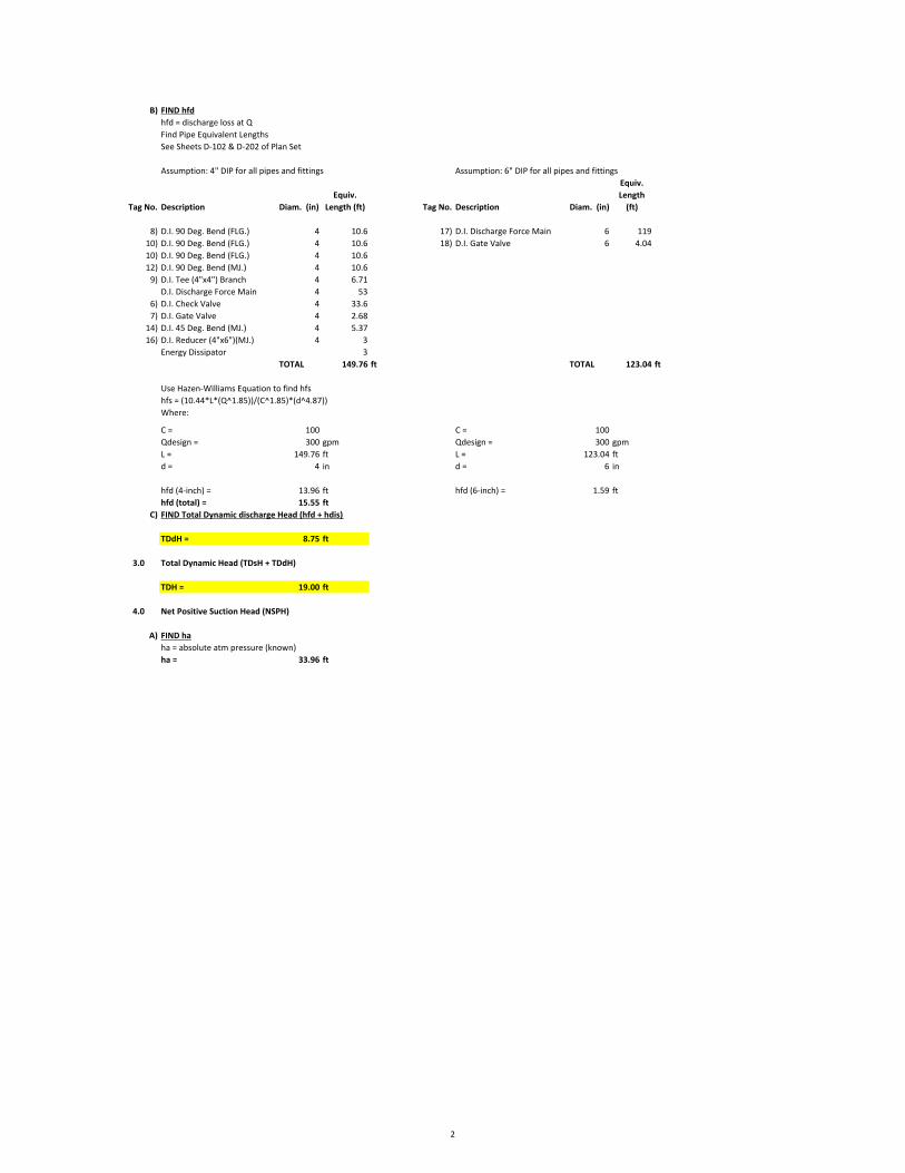
B) FIND hfdhfd = discharge loss at QFind Pipe Equivalent LengthsSee Sheets D-102 & D-202 of Plan Set
Assumption: 4" DIP for all pipes and fittings Assumption: 6" DIP for all pipes and fittings
Tag No. Description Diam. (in)Equiv.
Length (ft) Tag No. Description Diam. (in)
Equiv. Length
(ft)
8) D.I. 90 Deg. Bend (FLG.) 4 10.6 17) D.I. Discharge Force Main 6 11910) D.I. 90 Deg. Bend (FLG.) 4 10.6 18) D.I. Gate Valve 6 4.0410) D.I. 90 Deg. Bend (FLG.) 4 10.612) D.I. 90 Deg. Bend (MJ.) 4 10.6
9) D.I. Tee (4"x4") Branch 4 6.71D.I. Discharge Force Main 4 53
6) D.I. Check Valve 4 33.67) D.I. Gate Valve 4 2.68
14) D.I. 45 Deg. Bend (MJ.) 4 5.3716) D.I. Reducer (4"x6")(MJ.) 4 3
Energy Dissipator 3TOTAL 149.76 ft TOTAL 123.04 ft
Use Hazen-Williams Equation to find hfshfs = (10.44*L*(Q^1.85))/(C^1.85)*(d^4.87))Where:
C = 100 C = 100Qdesign = 300 gpm Qdesign = 300 gpmL = 149.76 ft L = 123.04 ftd = 4 in d = 6 in
hfd (4-inch) = 13.96 ft hfd (6-inch) = 1.59 fthfd (total) = 15.55 ft
C) FIND Total Dynamic discharge Head (hfd + hdis)
TDdH = 8.75 ft
3.0 Total Dynamic Head (TDsH + TDdH)
TDH = 19.00 ft
4.0 Net Positive Suction Head (NSPH)
A) FIND haha = absolute atm pressure (known)ha = 33.96 ft
2

B) FIND hpvahvpa = absolute vapor pressureSee Saturated Water Vapor Pressure vs. Temperature Table @ 75 degrees Fahrenheit
hpva = 0.435 psiaConvert pressure (psia) to head (ft)head = (pressure*2.31)/SGSG for Water = 1hpva = (0.43485*2.31)/1hpva = 1.00 ft
C) Calculate NPSHa @ Design Flow (Available)
NPSHa = ha - hvpa - hst - hfsNPSHa = 22.70 ft
D) Calculate NPSHr @ Design Flow (Required)
NPSHr = 6.5 ft (From Mfg. Curve - Feet of loss at rated flow)
E) FIND NPSH Excess AvailableNPSH Excess = NPSHa - NPSHrNPSH Excess Available = 16.20 ft
5.0 DETERMINE Priming Lift
Priming Lift (max) = 25 ft (Determined by pump manufacturer)
Priming Lift (PS A) = Pump CL - High Liquid Level High Liquid Level = 4.5 ftPriming Lift = 6.80 ft
Priming Lift Analasis: OK (Ok, if Pump Mafg. Priming lift is greater than project's.
3

6.0 DETERMINE System Curves-6.80
C = 100 C = 100 C = 100D = 4 in D = 4 in D = 6 in
0.33 ft 0.33 ft 0.50 ftTDH
Q V hfs NPSHa TDsH V hfd TDdH V hfd TDdH TDH(gpm) (ft/s) (ft) (ft) (ft) (ft/s) (ft) (ft) (ft/s) (ft) (ft) (ft)
0 0.00 0.00 25.16 7.80 0.00 0.00 0.00 0.29 0.00 0.00 1.0050 1.28 0.09 25.07 7.89 1.28 0.51 0.51 0.64 0.06 0.06 1.65
100 2.55 0.32 24.83 8.12 2.55 1.83 1.83 0.63 0.21 0.21 3.36150 3.83 0.68 24.47 8.48 3.83 3.87 3.87 0.62 0.44 0.44 5.99200 5.11 1.16 23.99 8.96 5.11 6.59 6.59 0.61 0.75 0.75 9.50250 6.38 1.75 23.40 9.55 6.38 9.96 9.96 0.60 1.14 1.14 13.85300 7.66 2.46 22.70 10.26 7.66 13.96 13.96 0.58 1.59 1.59 19.00350 8.94 3.27 21.89 11.07 8.94 18.56 18.56 0.56 2.12 2.12 24.95400 10.21 4.18 20.97 11.98 10.21 23.76 23.76 0.54 2.71 2.71 31.66450 11.49 5.20 19.95 13.00 11.49 29.55 29.55 0.51 3.37 3.37 39.12500 12.77 6.32 18.83 14.12 12.77 35.91 35.91 0.48 4.09 4.09 47.32550 14.04 7.54 17.61 15.34 14.04 42.83 42.83 0.45 4.88 4.88 56.25600 15.32 8.86 16.30 16.66 15.32 50.31 50.31 0.42 5.74 5.74 65.90
7.0 Manufacturer Curves
Pump: Godwin Dri-Prime NC80RPM: 1400 1600 1800
Q NPSHrQ TDH TDH TDH (gpm) (ft)
(gpm) (ft) (ft) (ft) 0 60 48.00 63 79 50 6
50 45.00 58 75 100 6100 40.00 55 70 150 6150 37.00 50 65 200 6200 32.00 45 58 250 6250 27.00 38 54 300 6.5300 20.00 32 46 350 7350 15.00 26 38 400 7.5400 9.00 19 32450 12 24500 16550600
8.0 Final Performance Curve
9.0 Final NPSH Curve
hdis =
TOTAL DYNAMIC suction HEAD TOTAL DYNAMIC discharge HEAD
Performance CurveNPSHr Curve
TOTAL DYNAMIC discharge HEAD
0.00
10.00
20.00
30.00
40.00
50.00
60.00
70.00
80.00
90.00
0 50 100 150 200 250 300 350 400 450 500 550 6001400 RPM System Curve 1600rpm 1800rpm
OPERATING POINT
0
5
10
15
20
25
30
0 50 100 150 200 250 300 350 400
NPSHr NPSHa
NPSH = 16 FT @ 300 GPM
4

EXHIBIT 2.2
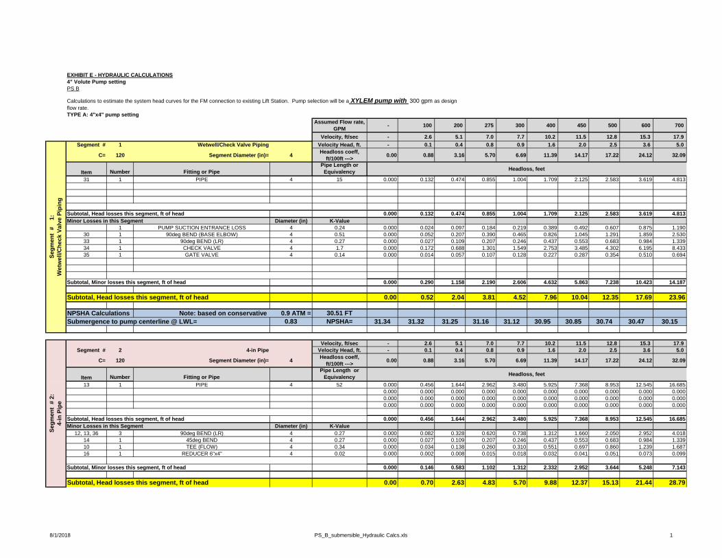
EXHIBIT E - HYDRAULIC CALCULATIONS4" Volute Pump settingPS B
TYPE A: 4"x4" pump settingAssumed Flow rate,
GPM - 100 200 275 300 400 450 500 600 700
Velocity, ft/sec - 2.6 5.1 7.0 7.7 10.2 11.5 12.8 15.3 17.9 Segment # 1 Wetwell/Check Valve Piping Velocity Head, ft. - 0.1 0.4 0.8 0.9 1.6 2.0 2.5 3.6 5.0
C= 120 Segment Diameter (in)= 4 Headloss coeff, ft/100ft ---> 0.00 0.88 3.16 5.70 6.69 11.39 14.17 17.22 24.12 32.09
Item Number Fitting or PipePipe Length or
Equivalency31 1 PIPE 4 15 0.000 0.132 0.474 0.855 1.004 1.709 2.125 2.583 3.619 4.813
Subtotal, Head losses this segment, ft of head 0.000 0.132 0.474 0.855 1.004 1.709 2.125 2.583 3.619 4.813Minor Losses in this Segment Diameter (in) K-Value
1 PUMP SUCTION ENTRANCE LOSS 4 0.24 0.000 0.024 0.097 0.184 0.219 0.389 0.492 0.607 0.875 1.19030 1 90deg BEND (BASE ELBOW) 4 0.51 0.000 0.052 0.207 0.390 0.465 0.826 1.045 1.291 1.859 2.53033 1 90deg BEND (LR) 4 0.27 0.000 0.027 0.109 0.207 0.246 0.437 0.553 0.683 0.984 1.33934 1 CHECK VALVE 4 1.7 0.000 0.172 0.688 1.301 1.549 2.753 3.485 4.302 6.195 8.43335 1 GATE VALVE 4 0.14 0.000 0.014 0.057 0.107 0.128 0.227 0.287 0.354 0.510 0.694
Subtotal, Minor losses this segment, ft of head 0.000 0.290 1.158 2.190 2.606 4.632 5.863 7.238 10.423 14.187
Subtotal, Head losses this segment, ft of head 0.00 0.52 2.04 3.81 4.52 7.96 10.04 12.35 17.69 23.96
NPSHA Calculations Note: based on conservative 0.9 ATM = 30.51 FTSubmergence to pump centerline @ LWL= 0.83 NPSHA= 31.34 31.32 31.25 31.16 31.12 30.95 30.85 30.74 30.47 30.15
Velocity, ft/sec - 2.6 5.1 7.0 7.7 10.2 11.5 12.8 15.3 17.9 Segment # 2 4-in Pipe Velocity Head, ft. - 0.1 0.4 0.8 0.9 1.6 2.0 2.5 3.6 5.0
C= 120 Segment Diameter (in)= 4 Headloss coeff, ft/100ft ---> 0.00 0.88 3.16 5.70 6.69 11.39 14.17 17.22 24.12 32.09
Item Number Fitting or PipePipe Length or
Equivalency13 1 PIPE 4 52 0.000 0.456 1.644 2.962 3.480 5.925 7.368 8.953 12.545 16.685
0.000 0.000 0.000 0.000 0.000 0.000 0.000 0.000 0.000 0.0000.000 0.000 0.000 0.000 0.000 0.000 0.000 0.000 0.000 0.0000.000 0.000 0.000 0.000 0.000 0.000 0.000 0.000 0.000 0.000
Subtotal, Head losses this segment, ft of head 0.000 0.456 1.644 2.962 3.480 5.925 7.368 8.953 12.545 16.685Minor Losses in this Segment Diameter (in) K-Value
12, 13, 36 3 90deg BEND (LR) 4 0.27 0.000 0.082 0.328 0.620 0.738 1.312 1.660 2.050 2.952 4.01814 1 45deg BEND 4 0.27 0.000 0.027 0.109 0.207 0.246 0.437 0.553 0.683 0.984 1.33910 1 TEE (FLOW) 4 0.34 0.000 0.034 0.138 0.260 0.310 0.551 0.697 0.860 1.239 1.68716 1 REDUCER 6"x4" 4 0.02 0.000 0.002 0.008 0.015 0.018 0.032 0.041 0.051 0.073 0.099
Subtotal, Minor losses this segment, ft of head 0.000 0.146 0.583 1.102 1.312 2.332 2.952 3.644 5.248 7.143
Subtotal, Head losses this segment, ft of head 0.00 0.70 2.63 4.83 5.70 9.88 12.37 15.13 21.44 28.79
Calculations to estimate the system head curves for the FM connection to existing Lift Station. Pump selection will be a XYLEM pump with 300 gpm as design flow rate.
Headloss, feet
Headloss, feet
Segm
ent
# 2:
4-
in P
ipe
Segm
ent
#
1:
Wet
wel
l/Che
ck V
alve
Pip
ing
8/1/2018 PS_B_submersible_Hydraulic Calcs.xls 1
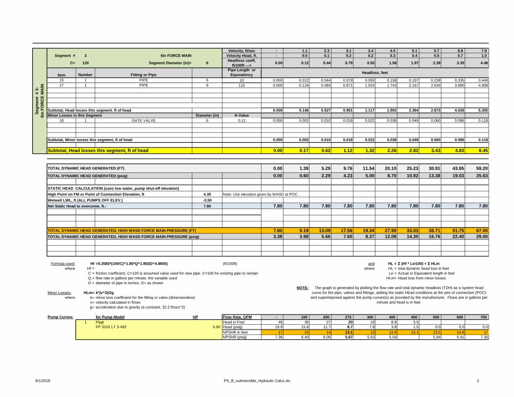
Velocity, ft/sec - 1.1 2.3 3.1 3.4 4.5 5.1 5.7 6.8 7.9 Segment # 3 6in FORCE MAIN Velocity Head, ft. - 0.0 0.1 0.2 0.2 0.3 0.4 0.5 0.7 1.0
C= 120 Segment Diameter (in)= 6 Headloss coeff, ft/100ft ---> 0.00 0.12 0.44 0.79 0.93 1.58 1.97 2.39 3.35 4.46
Item Number Fitting or PipePipe Length or
Equivalency15 1 PIPE 6 10 0.000 0.012 0.044 0.079 0.093 0.158 0.197 0.239 0.335 0.44617 1 PIPE 6 110 0.000 0.134 0.484 0.871 1.024 1.743 2.167 2.634 3.690 4.908
Subtotal, Head losses this segment, ft of head 0.000 0.146 0.527 0.951 1.117 1.902 2.364 2.873 4.026 5.355Minor Losses in this Segment Diameter (in) K-Value
18 1 GATE VALVE 6 0.12 0.000 0.002 0.010 0.018 0.022 0.038 0.049 0.060 0.086 0.118
Subtotal, Minor losses this segment, ft of head 0.000 0.002 0.010 0.018 0.022 0.038 0.049 0.060 0.086 0.118
Subtotal, Head losses this segment, ft of head 0.00 0.17 0.62 1.12 1.32 2.26 2.82 3.43 4.83 6.45
TOTAL DYNAMIC HEAD GENERATED (FT) 0.00 1.39 5.29 9.76 11.54 20.10 25.23 30.91 43.95 59.20TOTAL DYNAMIC HEAD GENERATED (psig) 0.00 0.60 2.29 4.23 5.00 8.70 10.92 13.38 19.03 25.63
STATIC HEAD CALCULATION (uses low water, pump shut-off elevation)High Point on FM or Point of Connection Elevation, ft 4.30 Note: Use elevation given by WASD at POCWetwell LWL, ft (ALL PUMPS OFF ELEV.) -3.50Net Static Head to overcome, ft.: 7.80 7.80 7.80 7.80 7.80 7.80 7.80 7.80 7.80 7.80 7.80
TOTAL DYNAMIC HEAD GENERATED, HIGH WASD FORCE MAIN PRESSURE (FT) 7.80 9.19 13.09 17.56 19.34 27.90 33.03 38.71 51.75 67.00TOTAL DYNAMIC HEAD GENERATED, HIGH WASD FORCE MAIN PRESSURE (psig) 3.38 3.98 5.66 7.60 8.37 12.08 14.30 16.76 22.40 29.00
Formula used: Hf =0.2083*(100/C)^1.85*Q^1.85/(D^4.8655) (ft/100ft) and HL = Σ (Hf * Le/100) + Σ HLmwhere Hf = where HL = total dynamic head loss in feet
C = friction coefficient, C=120 is assumed value used for new pipe, C=100 for existing pipe to remain Le = Actual or Equivalent length in feetQ = flow rate in gallons per minute, the variable used HLm= Head loss from minor lossesD = diameter of pipe in inches, D= as shown
NOTE:Minor Losses: HLm= k*(v^2)/2g
where k= minor loss coefficient for the fitting or valve (dimensionless)v= velocity calculated in ft/secg= acceleration due to gravity (a constant, 32.2 ft/sec^2)
Pump Curves: for Pump Model HP Flow Rate, GPM - 100 200 275 300 400 450 500 600 700 1 Flygt Head in Feet 46 36 27 20 18 8.8 3.5
FP 3102 LT 3-492 5.00 Head (psig) 19.9 15.6 11.7 8.7 7.8 3.8 1.5 0.0 0.0 0.0NPSHR in feet 17 15 14 13.1 13 12.8 13.1 13.5 14.8 17NPSHR (psig) 7.36 6.49 6.06 5.67 5.63 5.54 5.84 6.41 7.36
Headloss, feet
The graph is generated by plotting the flow rate and total dynamic headloss (TDH) as a system head curve for the pipe, valves and fittings, adding the static HEad conditions at the pint of connection (POC)
and superimposed against the pump curves(s) as provided by the manufacturer. Flows are in gallons per minute and head is in feet.
Segm
ent
# 3:
6in
FOR
CE
MA
IN
8/1/2018 PS_B_submersible_Hydraulic Calcs.xls 2

0.00
10.00
20.00
30.00
40.00
50.00
60.00
70.00
80.00
- 100 200 300 400 500 600 700 800
Tota
l Dyn
amic
Hea
d, ft
Flow Rate, gpm
HIGH WASD PRESSURE
Flygt FP 3102 LT 3 ~494(5 HP)
290 GPM @ 19 ft TDH
Flygt FP 3102 LT3 ~ 492
0.00
5.00
10.00
15.00
20.00
25.00
30.00
35.00
- 100 200 300 400 500 600 700 800
Tota
l Dyn
amic
Hea
d, ft
Flow Rate, gpm
NPSH Values
NPSHA @ LWL NPSHr-FLYGT
Adequate NPSH provided, 13'
8/1/2018 PS_B_submersible_Hydraulic Calcs.xls 1

EXHIBIT 3
1740

EXHIBIT 4

EXHIBIT 4 - CYCLE TIME CALCULATIONS
RV PARK WET WELL STORAGE CALCULATIONS PS-B
Parameters of Wet well:
Diameter, D( ):
D 6 ft⋅:=
Area, A ( 2):
A π
D2
2⋅:=
A 28.274 ft2⋅=
Effec ve Wetwell Volume, V 1 (gal) :
H1 1.0 ft⋅:= Where H1 = "Lead Pump On" eleva on - "All Pumps Off" eleva on
V1 A H1⋅7.48 gal⋅
1 ft3⋅⋅:=
V1 211.492 gal⋅=
Cycle Time, T (min.):
Q 300galmin
:= V2 15755gal:= Vtotal V1 V2+:=
Vtotal 1.597 104× gal⋅=Where T = Cycle Time (min.)V1 = Wetwell Volume (gal.)Q = Design Peak Flow (GPM)V2 = Deten on Area (gal.)
TVtotal
Q:=
T 53.222 min⋅=
Pump Starts per Hour, Ps:
Ps2 60min
T⋅:= Ps2 1.127= Ps1
Ps22
:= Ps1 0.564=
The pump station demonstrates 0.79 starts per hour; but each pumpalternates and starts 0.39 times per hour (<6, OK).
V:\2156\active\215614127\calcs\Permit\Wet Well Storage Calculations_permit.xmcd

EXHIBIT 4.1

Exhibit 4.1

Total Drainage System Storage Volume
Project: Marco Naples RV Park Drainage ImprovementsProject No.: 215614127
By: MJMLast Updated: 08/01/18
Basin Structure No. Dia. (in.) Area (s.f.) Length (ft.) Volume (c.f.) GallonsV(P-1) 24 3.142 64 201 1504V(P-2) 24 3.142 82 258 1927V(P-3) 24 3.142 65 204 1527V(P-4) 24 3.142 65 204 1527V(P-5) 24 3.142 34 107 799V(P-6) 24 3.142 76 239 1786
V(DA-2) - 2691 1 2691 20129V(DA-2) - 618 0.5 309 2311
TOTAL: 388 4,213 31,511TOTAL: 0 0.0
TOTAL VOLUMES OF STORAGECF GALL.
Pipe + Detention
Area 4,212.65 31,510.66Effective
Storage (50%)2106.33 15755.33
PROP. PIPES
PROP. DETENTION
AREA

B
A
R
E
F
O
O
T
W
IL
L
IA
M
S
R
D
1st ST (PRIVATE)
HA
BIT
AT
D
R
LIN
DA
A
VE
(P
RIV
AT
E)
SA
RA
A
VE
(P
RIV
AT
E)
JE
RE
MY
A
VE
(P
RIV
AT
E)
CL
AIR
E A
VE
(P
RIV
AT
E)
BE
TH
A
VE
(P
RIV
AT
E)
DA
NIE
L A
VE
(P
RIV
AT
E)
LO
RIN
A
VE
(P
RIV
AT
E)
JU
DY
A
VE
(P
RIV
AT
E)
JA
ME
S A
VE
(P
RIV
AT
E)
2nd ST (PRIVATE)
7
t
h
A
V
E
(
P
R
IV
A
T
E
)
2nd ST (PRIVATE)
3rd ST (PRIVATE)
4th ST (PRIVATE)
5th ST (PRIVATE)
6th ST (PRIVATE)
7th AVE (PRIVATE)
1st ST (PRIVATE)
P
E
N
N
Y
R
D
(
P
R
IV
A
T
E
)
LA
RR
Y A
VE
(P
RIV
AT
E)
GradyMinor
Civil Engineers ● Land Surveyors ● Planners ● Landscape Architects
Cert. of Auth. EB 0005151 Cert. of Auth. LB 0005151 Business LC 26000266
Q. Grady Minor and Associates, P.A.
3800 Via Del Rey
Bonita Springs, Florida 34134
Bonita Springs: 239.947.1144 www.GradyMinor.com Fort Myers: 239.690.4380
0
40' 80'20'
SCALE: 1" = 40'
B
7
A
7

EXHIBIT 5.1
Picture3
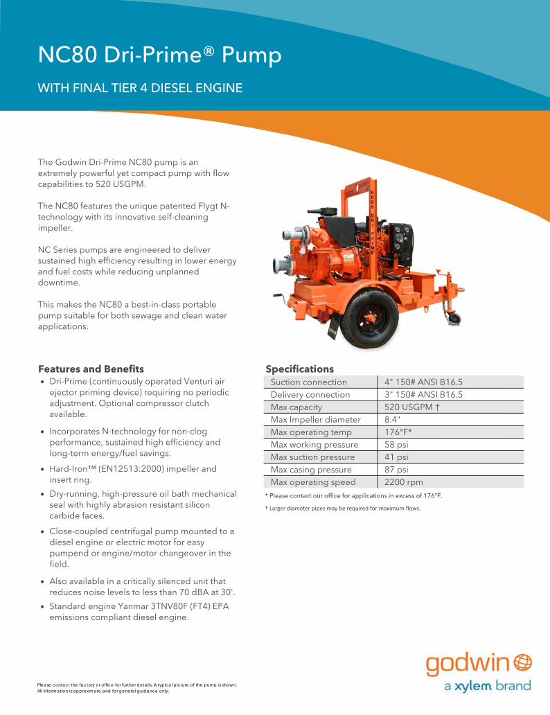
Features and Benefits Specifications Suction connection 4" 150# ANSI B16.5
Delivery connection 3" 150# ANSI B16.5Max capacity 520 USGPM †Max Impeller diameter 8.4"
Max operating temp 176°F*Max working pressure 58 psiMax suction pressure 41 psi
Max casing pressure 87 psiMax operating speed 2200 rpm
* Please contact our office for applications in excess of 176°F.
† Larger diameter pipes may be required for maximum flows.
Picture 101
Please contact the factory or office for further details. A typical picture of the pump is shown.All information is approximate and for general guidance only.
The Godwin Dri-Prime NC80 pump is an extremely powerful yet compact pump with flow capabilities to 520 USGPM.
The NC80 features the unique patented Flygt N-technology with its innovative self-cleaning impeller.
NC Series pumps are engineered to deliver sustained high efficiency resulting in lower energy and fuel costs while reducing unplanned downtime.
This makes the NC80 a best-in-class portable pump suitable for both sewage and clean water applications.
Dri-Prime (continuously operated Venturi air ejector priming device) requiring no periodic adjustment. Optional compressor clutch available.
Incorporates N-technology for non-clog performance, sustained high efficiency and long-term energy/fuel savings.
Hard-Iron™ (EN12513:2000) impeller and insert ring.
Dry-running, high-pressure oil bath mechanical seal with highly abrasion resistant silicon carbide faces.
Close-coupled centrifugal pump mounted to a diesel engine or electric motor for easy pumpend or engine/motor changeover in the field.
Also available in a critically silenced unit that reduces noise levels to less than 70 dBA at 30'.
Standard engine Yanmar 3TNV80F (FT4) EPA emissions compliant diesel engine.
NC80 Dri-Prime® PumpWITH FINAL TIER 4 DIESEL ENGINE

Performance Curve Materials
Engine option 1 Engine option 2Yanmar, 3TNV80F (FT4), 18 HP @ 2200 rpm #N/A
Impeller diameter 8.4" -
Pump speed 2200 rpm Pump speed 2200 rpm
Suction Lift Table Suction Lift Table
Total Delivery Head (feet) Total Delivery Head (feet)
20 52 69 79 92 20 52 79 92
Output (USGPM) Output (USGPM)
10 377 266 184 131 49 10 377 266 131 49
15 361 246 148 105 - 15 361 246 105 -
20 341 213 131 82 - 20 341 213 82 -
25 295 197 98 66 - 25 295 197 66 -
Fuel capacity: 30 US Gal Fuel capacity: 30 US Gal
Max Fuel consumption @ 2200 rpm: 1.2 US Gal/hr #N/A
Max Fuel consumption @ 1800 rpm: 0.7 US Gal/hr #N/A
Weight (Dry): 1,900 lbs Weight (Dry): 00 lbs
Weight (Wet): 2,120 lbs Weight (Wet): 00 lbs
Dimensions: (L) 102" x (W) 54" x (H) 70" -
Drawing1
Picture 10284 Floodgate Road Reference number : 200GPA0000163Bridgeport, NJ 08014 USA Date of issue : (856) 467-3636 . Fax (856) 467-4841 Issue : -
69
Total Suction
Head (feet)
Total Suction
Head (feet)
Pump casing & suction cover
Cast iron BS1561:1997
WearplatesFront - Hard Iron EN12513:2000Rear - Cast Iron BS1561:1997 0
Pump Shaft Carbon steel BS970:1991 817M40T
Impeller Hard Iron EN12513:2000
Non-return Valve body
Cast iron BS1561:1997
Mechanical SealSilicon carbide face; Viton elastomers; Stainless steel body
November 3, 2015
www.godwinpumps.com© 2015 Xylem, Inc. All rights reserved. Godwin is a trademark of Xylem Dewatering Solutions, Inc., a wholly-owned subsidiary of Xylem Inc. Specifications and illustrations are subject to revision without notice. Xylem makes no representation regarding the completeness or accuracy of this information and is not liable for any direct or indirect damages arising from or relating to this information or its use.
184
148
131
98
Performance data provided in tables is based on water tests at sea level and 20°C ambient. All information is approximate and for general guidance only. Please contact the factory or office for further details.
Performance data provided in tables is based on water tests at sea level and 20°C ambient. All information is approximate and for general guidance only. Please contact the factory or office for further details.
2200 rpm
2000 rpm
1800 rpm
1600 rpm
1400 rpm
1200 rpm 27%
20%28%
35%
41%
45%
46%
43%
36%
0
4
8
12
16
20
24
28
32
0 13 26 39 52 65 78 91 104 117 130
0
20
40
60
80
100
0 65 130 195 260 325 390 455 520
Hea
d (m
eter
s)
Flow (m³/hr)
Hea
d (f
eet)
Flow (USGPM)

Suction Lift: 7 ft Assumption
Suction Pipe: 15 ft 4" DIP, (1)90°, (1)Ent Loss Assumption
Discharge Head: 0 ft Assumption
Discharge Pipe: ?
Performance - 197 mm Impeller | Variable Speed Curve
Power
NPSHr
GODWIN PUMPS OF AMERICA, 84 FLOODGATE ROAD, BRIDGEPORT, NJ, 08014. Tel - 856-467-3636. Fax - 856-467-4841. godwinpumps.com
GODWIN DRI-PRIME® NC80ONE (1) VARIABLE SPEED PUMP | SYSTEM CURVE
RV RESORT STORMWATER PUMP STATIONFLORIDA
NC
80
2200 rpm
2000 rpm
1800 rpm
1600 rpm
1400 rpm
0
2
4
6
8
10
0 20 40 60 80 100 120 140
0
5
10
15
0 50 100 150 200 250 300 350 400 450 500 550 600 650
Po
wer
(kW
)
Per Unit Flow (m^3/hr)
Po
wer
(h
p)
Per Unit Flow (USGPM)
0
2
4
6
8
0 20 40 60 80 100 120 140
0
10
20
30
0 50 100 150 200 250 300 350 400 450 500 550 600 650
NP
SH
r (m
etre
s)
Per Unit Flow (m^3/hr)
NP
SH
r (F
ee
t)
Per Unit Flow (USGPM)
2000 rpm
1800 rpm
1600 rpm
1400 rpm
35%40%
45%
51%
45%
40%35%
31%25%
minimum capacity
2200 rpm
0
5
10
15
20
25
30
35
0 20 40 60 80 100 120 140
0
10
20
30
40
50
60
70
80
90
100
110
120
130
0 50 100 150 200 250 300 350 400 450 500 550 600 650
Hea
d (
met
res)
System Flow (m^3/hr)
Hea
d (
Fee
t)
System Flow (USGPM)
1 Pump Performance Curve
System
400-GPM @ 21-ft TDH
NC80.18036.bjc.RV Resort Stormwater Pump Station.xlsm 7/25/2018

EXHIBIT 5.2
Open screw ty pe cutting impellers and single v olute casing f or liquidscontaining long f ibres and large solids. F3153 and F3171 are newdesigns with high ef f iciency combined with excellent cutting perf ormance.
Head
492 186mm
43.3%
0123456789
10111213141516171819202122232425262728293031323334353637383940414243444546474849[ft]
0 50 100 150 200 250 300 350 400 450 [US g.p.m.]
Impeller
Frequency
Motor
Rated v oltage
-
Rated power
Rated speed
Number of poles
Rated current
240 V60 Hz
5 hp
4
1740 rpm
13 A
FP 3102 LT 3~ 492
Motor #
3~
Suction Flange Diameter
Weight
7"
10"
Ø4"
18"
2"
11"
4"
8"
Z Z
Z Z
FP 3102 LT
STD. CL ASS 1 2 5C.I. FL ANGE(NOM . SIZE)
2"
B OLT
GUIDE BARS
80
DischP ump
(lbs)
240
538 63 00 B
5399
88 0127Pn i EGC
4 "/4 "
DIME NS ION TO E NDS OF GUIDE B A RS*
V IE WCL
OF D
ISC
H
RE F.LINE
RE F.LINE
(TO FURTHE S T P OINT)
MIN
MIN LE V E L
RE F.LINE
caleS
Dr awn
Reg no
Dat ebyChec k ed
by
DRAW ING
AUTOCAD
Denom inat ion
Dimensional drwg
338 16"
114
4916
153 4
*101 4
234
241 2
23 4
1734
3714
2612
712
53 4 71 2
612
234
978
Ø34
(4x)
Impeller diameter 186 mmNumber of blades 2
F3102.181 18-11-4AL-W 5hp
Stator v ariant 68
Phases
Starting current 73.1 A
Technical specification
Note: Picture might not correspond to the current configuration.
Power f actor
Motor ef f iciency
1/1 Load3/4 Load1/2 Load
1/1 Load3/4 Load1/2 Load
0.840.790.69
85.0 %85.5 %84.5 %
3 15/16 inchCurve ISO
P - Semi permanent, WetInstallation:
Configuration
Impeller material Spherodial graphite cast iron
General
Discharge Flange Diameter 3 15/16 inch
Water, pure
Standard
Last updateCreated on
7/26/2018
Created byProject IDProject

Head
Pump efficiency
Overall eff iciency
Pow er input P1
Shaft pow er P2
492 186mm
43.3%
492 186mm492 186mm
492 186mm (P2)
492 186mm (P1)
0
4
8
12
16
20
24
28
32
36
40
44
[ft]
0
5
10
15
20
25
30
35
40
[%]
0.0
0.5
1.0
1.5
2.0
2.5
3.0
3.5
4.0
[hp]
0 40 80 120 160 200 240 280 320 360 400 440 480 [US g.p.m.]
Motor #
60 Hz
Phases 3~
240 VNumber of poles 4
Rated power 5 hp
Starting currentRated current 13 A
Rated speed 1740 rpm
F3102.181 18-11-4AL-W 5hp
Stator variantNumber of blades 2
Power factor
FP 3102 LT 3~ 492
Suction Flange Diameter
Performance curve
Pump
Impeller diameter 75/16"
Motor
Rated voltage
73.1 A
Motor efficiency
1/1 Load
3/4 Load
1/2 Load
1/1 Load
3/4 Load
1/2 Load
Frequency68
0.84
85.0 %
0.79
0.69
85.5 %
84.5 %
100 mm
Curve ISO
Discharge Flange Diameter 3 15/16 inch
Water, pure
Last updateCreated on
7/26/2018
Created byProject IDProject
Head
492 186mm
43.3%
0
1
2
3
4
5
6
7
8
9
10
11
12
13
14
15
16
17
18
19
20
21
22
23
24
25
26
27
28
29
30
31
32
33
34
35
36
37
38
39
40
41
42
43
44
45
46
47
48
49
[ft]
0 40 80 120 160 200 240 280 320 360 400 440 480 [US g.p.m.]
FP 3102 LT 3~ 492Duty Analysis
Curve ISOWater, pure
Curve issue 12
Last updateCreated on
7/26/2018
Created byProject IDProject
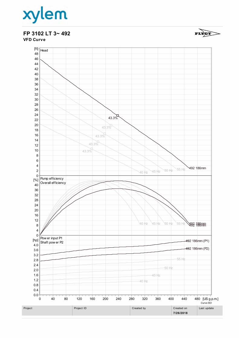
Head
Pump efficiency
Overall eff iciency
Pow er input P1
Shaft pow er P2
55 Hz
43.3%
50 Hz
43.3%
45 Hz
43.3%
40 Hz
43.3%
492 186mm
43.3%
55 Hz50 Hz45 Hz40 Hz 492 186mm492 186mm
55 Hz
50 Hz
45 Hz
40 Hz
492 186mm (P2)
492 186mm (P1)
0
2
4
6
8
10
12
14
16
18
20
22
24
26
28
30
32
34
36
38
40
42
44
46
48
[ft]
0
4
8
12
16
20
24
28
32
36
40
[%]
0.0
0.4
0.8
1.2
1.6
2.0
2.4
2.8
3.2
3.6
4.0
[hp]
0 40 80 120 160 200 240 280 320 360 400 440 480 [US g.p.m.]
FP 3102 LT 3~ 492VFD Curve
Curve ISO
Last updateCreated on
7/26/2018
Created byProject IDProject
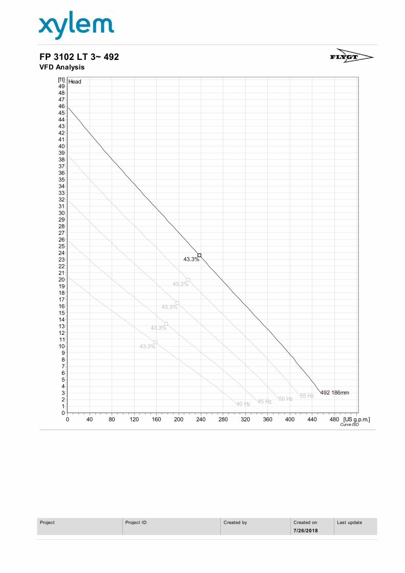
Head
55 Hz
43.3%
50 Hz
43.3%
45 Hz
43.3%
40 Hz
43.3%
492 186mm
43.3%
0123456789
10111213141516171819202122232425262728293031323334353637383940414243444546474849[ft]
0 40 80 120 160 200 240 280 320 360 400 440 480 [US g.p.m.]
FP 3102 LT 3~ 492VFD Analysis
Curve ISO
Last updateCreated on
7/26/2018
Created byProject IDProject
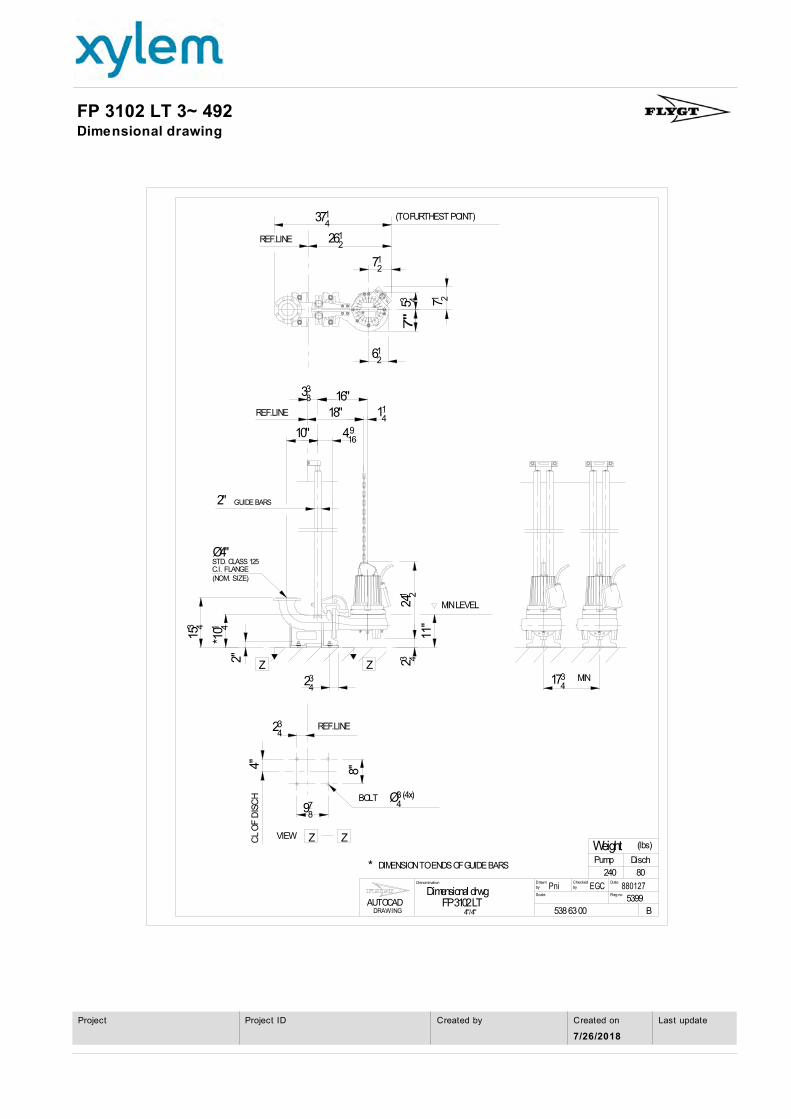
FP 3102 LT 3~ 492Dimensional drawing
Weight
7"
10"
Ø4"
18"
2"
11"
4" 8"
Z Z
Z Z
FP 3102 LT
STD. CLASS 125C.I. FLANGE(NOM. SIZE)
2"
BOLT
GUIDE BARS
80
DischPump
(lbs)
240
538 63 00 B
5399
880127Pni EGC
4"/4"
DIMENSION TO ENDS OF GUIDE BARS*
VIEWCL
OF
DIS
CH
REF.LINE
REF.LINE
(TO FURTHEST POINT)
MIN
MIN LEVEL
REF.LINE
caleS
Drawn
Reg no
DatebyChecked
by
DRAWINGAUTOCAD
Denomination
Dimensional drwg
338 16"
114
4916
153 4
*101 4
234
241 2
23 4
1734
3714
2612
712
53 4 71 2
612
234
978
Ø34 (4x)
Last updateCreated on
7/26/2018
Created byProject IDProject

EXHIBIT 5.3

Exhibit 5.3
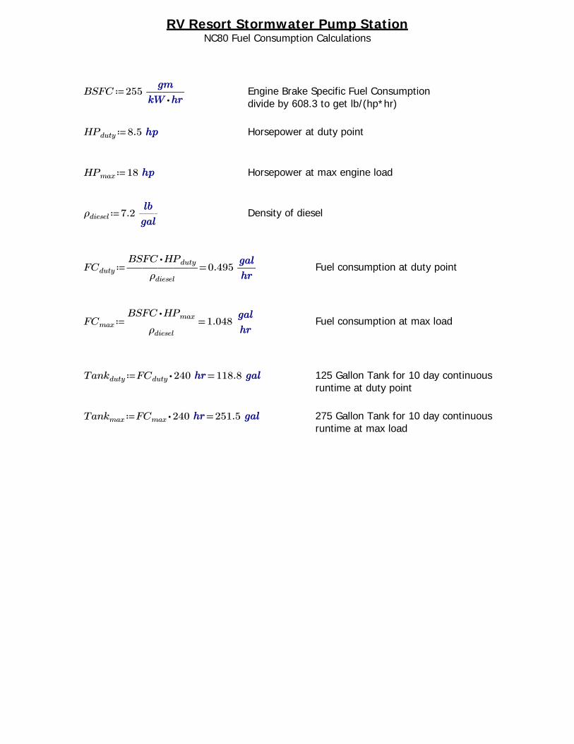
RV Resort Stormwater Pump StationNC80 Fuel Consumption Calculations
≔BSFC 255 ―――⋅
Engine Brake Specific Fuel Consumption divide by 608.3 to get lb/(hp*hr)
≔HPduty 8.5 Horsepower at duty point
≔HPmax 18 Horsepower at max engine load
≔ρdiesel 7.2 ―― Density of diesel
≔FCduty =―――――⋅BSFC HPduty
ρdiesel
0.495 ―― Fuel consumption at duty point
≔FCmax =―――――⋅BSFC HPmax
ρdiesel
1.048 ―― Fuel consumption at max load
≔Tankduty =⋅FCduty 240 118.8 125 Gallon Tank for 10 day continuous runtime at duty point
≔Tankmax =⋅FCmax 240 251.5 275 Gallon Tank for 10 day continuous runtime at max load

Lubrication System3.4L Capacity Shallow Oil Pan
Electrical System12V, 40A Alternator
Fuel SystemIn-line ML Fuel Injection Pump
Cooling SystemWater Pump, Belt-driven
Power Take OffFWH: SAE #5 t=124FW: SAE 7.5"
SPECIFICATIONEspecificacion
SDSA
CYLINDERS Cilindros
3
BORE X STROKE Diametro x Carrera
DISPLACEMENTCilindrada
80 x 84 (mm)3.14 x 3.31 (in)
1267 (cc)77.3 (ci)
COMBUSTION TYPETipo de Combustion
Indirect InjectionInyeccion Indirecta
ASPIRATIONAspiracion
Naturally AspiratedAspiracion Natural
GOVERNOR TYPETipo de Gobernador
MechanicalMecanico
INDUSTRIAL / ENGINES / TNV SERIES
Dimensions, Performance Data & Quick Specs 3TNV80F-SDSANET INTERMITTENT POWER (kW/hp)Potencia Neta Intermitente
16.4 / 21.9
RATED SPEED (RPM)Velocidad de Regimen
3000
LENGTH (w/fan) (in/mm)Longitud
22.4 / 570
WIDTH (in/mm)Ancho
17.4 / 443
HEIGHT (in/mm)Altura
22.6 / 574
DRY WEIGHT (lbs/kg)Peso en Seco
286 / 130
INDUSTRIAL / ENGINES / TNV SERIES
Final Tier 4Building off the proven TNV design, Yanmar has achieved superior exhaust emissions by improving the combustion chamber and increasing the displacement and compression ratio. Yanmar engines meet the strict NTE and NRTC test requirements for 2014 Final Tier 4.
Better Fuel Efficiency, Fewer EmissionsYanmar continues its reputation for superior starting characteristics by refining the combustion process to assure more precise fuel delivery and control. The result is reduced emissions, improved performance over a wide range of applications and increased fuel economy.
Now Even More ReliableThe new line of Final Tier 4 engines continues to build upon the legendary reliability of the Yanmar TNV line with a focus on vibration reduction and higher-strength materials. The result is an engine more than capable of handling the most demanding applications.
© 2014 Yanmar America Corp.Engine photo may not reflect actual specifications. IE-3TNV80F-SDSA-SS0114
35
30
25
20
15
10
5
0
Gro
ss O
utp
ut
To
rque
B.S
.F.C
.
N • m
g/kWh
1200 1400 1600 1800 2000 2200 2400 2600 2800 3000 3200 3400
Engine Speed min-1
125
100
75
50
25
0
360
340
320
300
280
260
240 kW
Torque
Output
B.S.F.C

EXHIBIT 6

123456789
1011121314151617181920212223242526272829303132333435363738
39404142434445464748495051
5253545556575859606162
A B C D E F G H IBUOYANCY CALCULATIONS FOR CIRCULAR DRAINAGE PUMP STATION
Checked by: Paul R. Duquette, PE
Site DataWater Elevation (ft) = 8.30 *Assume worst case of water at top of slabSoil Type = LimestoneSpecific Weight of Water, lb/ft^3 = 62.40
Structure DataTop of Well Elevation, ft (inside) = 8.30Bottom of Well Elevation, ft (Inside) = -2.00Elevation Diff. Water Elev. And Top of Well, ft = 0.00 =(F16-E11)Specific Weight of Concrete, lb/ft^3 = 135.00
Specific Weight of Submerged Limestone, lb/ft^3 = 63.00
Geometry
interior diameter A, ft = 6.00wall thickness B, ft = 0.83 10" Min. Pre-Cast, 12" Cast-in-Placebottom slab dimension C, ft = 8.67top slab thickness D, ft = 1.00bottom slab thickness E, ft = 1.00interior height F, ft = 10.30 =F16-F17exterior depth L, ft = 11.30 =C30+C28
Mod. E, ft = 1.00 =D27+G47
OutputVolume of Water Displaced, ft^3 = 521.56 =PI()*((C23/2)+C24)^2*(C29-F18)
Upward Force, ton = 16.27 =G35*62.4/2000
Structure Concrete Volume, ft^3 = 281.73=(C27*PI()*(C25/2)^2)+(C24*(2*PI()*((
C23/2)+C24)*C28))
Downward Force, ton = 21.13 =G38*150/2000
Downward Force DEFICIT, ton = 4.86 =G41-G37
Depth of Concrete Cast Inside, ft = 0.00
Force Due to Concrete Cast Inside, ton = 0.00 =G45*PI()*(C23/2)^2*135/2000
Increase in E Dimension (Base Slab Thickness, If Needed), ft = 0.00 0.00
Downward Force Due to Increased E Dimension, ton = 0.00 =G47*PI()*(D25/2)^2*135/2000
Downward Force Due to weight of soil on Bottom Slab Lip, ton = 7.15
=[(C25/2)^2)*3.14*C28)-(C23+2*C24)/2)^2)*3.14*C28)]*F20)/2000*0.5
Modified Downward Force Due to Increased E Dimension, ton = 28.28 =G41+G47+G51+G52
Modified Downward Force DEFICIT, ton = -12.01 =G37-G53BUOYANCY FAIL (YES/NO)? NO =IF(G55<0,"NO","YES")
Notes: FACTOR OF SAFETY= 1.74
1. Top slab/pump house not included in calculations.2. Downward Force DEFICIT is the force required to overcome buoyancy.3. Concrete Cast Inside includes interior walls and fillets.
Prepared By: Marlon J. Medina, PEComments: The October Water Table in this area is approximately 3.5', Stantec assumed a conservative approach of 8.30'.
Project: RV PARK - PS BProject No: 215614127
Date: August 1, 2018
V:\2156\active\215614127\calcs\Permit\RV PARK_Buoyancy Calcs.xlsRV PARK_Buoyancy Calcs.xls

EXHIBIT 7


EXHIBIT 8

Page 1 of 1
1/30/2015http://www.autocrane.com/img/T50-84_TALL-52_560740001.png
Page 1 of 1
1/30/2015http://www.autocrane.com/img/lrg-5005eh-load-chart.png