StorEdge Solution Applications (North America) · StorEdge Solution Applications Connection and...
63
SolarEdge StorEdge Solution Applications Connection and Configuration Guide For North America Version 1.2
Transcript of StorEdge Solution Applications (North America) · StorEdge Solution Applications Connection and...

SolarEdge
StorEdge Solution Applications
Connection and Configuration Guide
For North America
Version 1.2
Introduction
1
StorEdgeTM Solution Applications – Connection and Configuration
(North America)
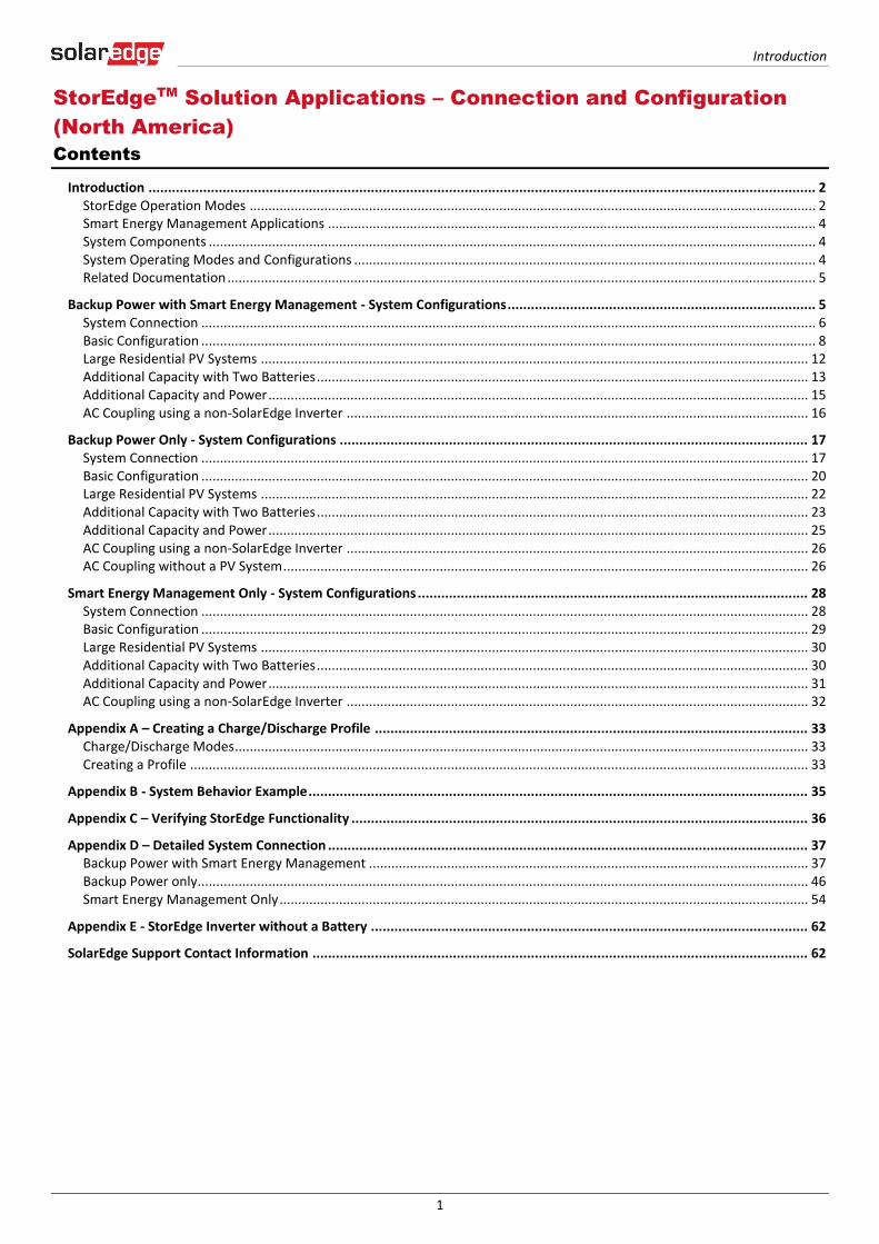
Contents
Introduction ........................................................................................................................................................................... 2 StorEdge Operation Modes ........................................................................................................................................................ 2 Smart Energy Management Applications ................................................................................................................................... 4 System Components ................................................................................................................................................................... 4 System Operating Modes and Configurations ............................................................................................................................ 4 Related Documentation .............................................................................................................................................................. 5
Backup Power with Smart Energy Management - System Configurations ............................................................................... 5 System Connection ..................................................................................................................................................................... 6 Basic Configuration ..................................................................................................................................................................... 8 Large Residential PV Systems ................................................................................................................................................... 12 Additional Capacity with Two Batteries .................................................................................................................................... 13 Additional Capacity and Power ................................................................................................................................................. 15 AC Coupling using a non-SolarEdge Inverter ............................................................................................................................ 16
Backup Power Only - System Configurations ........................................................................................................................ 17 System Connection ................................................................................................................................................................... 17 Basic Configuration ................................................................................................................................................................... 20 Large Residential PV Systems ................................................................................................................................................... 22 Additional Capacity with Two Batteries .................................................................................................................................... 23 Additional Capacity and Power ................................................................................................................................................. 25 AC Coupling using a non-SolarEdge Inverter ............................................................................................................................ 26 AC Coupling without a PV System ............................................................................................................................................. 26
Smart Energy Management Only - System Configurations .................................................................................................... 28 System Connection ................................................................................................................................................................... 28 Basic Configuration ................................................................................................................................................................... 29 Large Residential PV Systems ................................................................................................................................................... 30 Additional Capacity with Two Batteries .................................................................................................................................... 30 Additional Capacity and Power ................................................................................................................................................. 31 AC Coupling using a non-SolarEdge Inverter ............................................................................................................................ 32
Appendix A – Creating a Charge/Discharge Profile ............................................................................................................... 33 Charge/Discharge Modes .......................................................................................................................................................... 33 Creating a Profile ...................................................................................................................................................................... 33
Appendix B - System Behavior Example ................................................................................................................................ 35
Appendix C – Verifying StorEdge Functionality ..................................................................................................................... 36
Appendix D – Detailed System Connection ........................................................................................................................... 37 Backup Power with Smart Energy Management ...................................................................................................................... 37 Backup Power only.................................................................................................................................................................... 46 Smart Energy Management Only .............................................................................................................................................. 54
Appendix E - StorEdge Inverter without a Battery ................................................................................................................ 62
SolarEdge Support Contact Information ............................................................................................................................... 62
Introduction
2
Introduction
SolarEdge’s StorEdge Solution can be used for various applications that enable energy independence for system owners, by
utilizing a battery to store power and supply power as needed. The StorEdge Solution is based on and managed by the StorEdge
Inverter with Backup (referred to as “StorEdge inverter” or “inverter” throughout the document) for both PV and battery
management, and is compatible with the Tesla Powerwall Battery.
This document describes the main operating modes and applications of the StorEdge Solution with Backup.
NOTE
The StorEdge inverter requires CPU version 3.18xx and above. If an upgrade is required contact SolarEdge support for
an upgrade file and instructions.
StorEdge Operation Modes
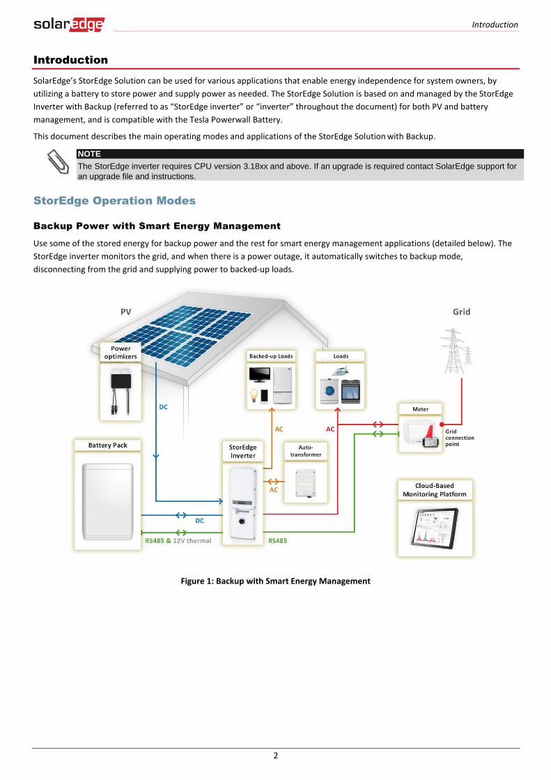
Backup Power with Smart Energy Management
Use some of the stored energy for backup power and the rest for smart energy management applications (detailed below). The
StorEdge inverter monitors the grid, and when there is a power outage, it automatically switches to backup mode,
disconnecting from the grid and supplying power to backed-up loads.
Figure 1: Backup with Smart Energy Management
Introduction
3
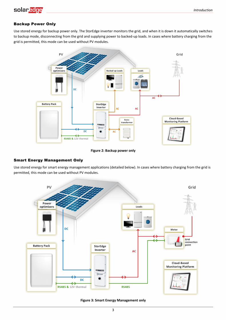
Backup Power Only
Use stored energy for backup power only. The StorEdge inverter monitors the grid, and when it is down it automatically switches
to backup mode, disconnecting from the grid and supplying power to backed-up loads. In cases where battery charging from the
grid is permitted, this mode can be used without PV modules.
Figure 2: Backup power only
Smart Energy Management Only
Use stored energy for smart energy management applications (detailed below). In cases where battery charging from the grid is
permitted, this mode can be used without PV modules.
Figure 3: Smart Energy Management only
Introduction
4
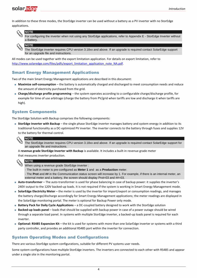
In addition to these three modes, the StorEdge inverter can be used without a battery as a PV inverter with no StorEdge
applications.
NOTE
For configuring the inverter when not using any StorEdge applications, refer to Appendix E - StorEdge Inverter without
a Battery.
NOTE
The StorEdge inverter requires CPU version 3.18xx and above. If an upgrade is required contact SolarEdge support
for an upgrade file and instructions.
All modes can be used together with the export limitation application. For details on export limitation, refer to
http://www.solaredge.com/files/pdfs/export_limitation_application_note_NA.pdf.
Smart Energy Management Applications
Two of the main Smart Energy Management applications are described in this document:
Maximize self-consumption – the battery is automatically charged and discharged to meet consumption needs and reduce
the amount of electricity purchased from the grid.
Charge/discharge profile programming – the system operates according to a configurable charge/discharge profile, for
example for time of use arbitrage (charge the battery from PV/grid when tariffs are low and discharge it when tariffs are
high).
System Components
The StorEdge Solution with Backup comprises the following components:
StorEdge Inverter with Backup – the single phase StorEdge inverter manages battery and system energy in addition to its
traditional functionality as a DC-optimized PV inverter. The inverter connects to the battery through fuses and supplies 12V
to the battery for thermal control.
NOTE
The StorEdge inverter requires CPU version 3.18xx and above. If an upgrade is required contact SolarEdge support for
an upgrade file and instructions.
A revenue grade StorEdge Inverter with Backup is available. It includes a built-in revenue grade meter
that measures inverter production.
NOTE
When using a revenue grade StorEdge inverter :
- The built-in meter is pre-configured as Meter 1 and as a Production meter.
- The Prot and ## in the Communication status screen will increase by 1. For example, if there is an internal meter, an
external meter and a battery, the screen should display Prot=03 and ##=03.
Auto-transformer – The auto-transformer is used for phase balancing in case of backup power: it supplies the inverter’s
240V output to the 120V backed-up loads. It is not required if the system is working in Smart Energy Management mode.
SolarEdge Electricity Meter – the meter is used by the inverter for import/export or consumption readings, and manages
the battery charge/discharge accordingly for Smart Energy Management applications; the meter readings are displayed in
the SolarEdge monitoring portal. The meter is optional for Backup Power only mode.
Battery Pack for Daily Cycle Applications – a DC-coupled battery designed to work with the StorEdge solution
Backed-up loads panel – loads that should be supplied with backup power in case of a power outage should be wired
through a separate load panel. In systems with multiple StorEdge inverter, a backed-up loads panel is required for each
inverter.
Optional: RS485 Expansion Kit – the kit is used for systems with more than one SolarEdge inverter or systems with a third
party controller, and provides an additional RS485 port within the inverter for connection.
System Operating Modes and Configurations
There are various StorEdge system configurations, suitable for different PV systems user needs.
Some system configurations have multiple StorEdge inverters. The inverters are connected to each other with RS485 and appear
under a single site in the monitoring portal.
Backup Power with Smart Energy Management - System Configurations
5
The next chapters describe each of these configurations for each of the three modes described above, and the required system
setup via the inverter LCD and internal buttons and via the monitoring portal (where applicable).
Backup Power with Smart Energy Management - System Configurations, page 5.
Backup Power Only - System Configurations, page 17.
Smart Energy Management Only - System Configurations, page 28.
Related Documentation
For detailed installation and configuration instructions of the system components, refer to the following installation guides:
StorEdge inverter and auto-transformer: http://www.solaredge.com/files/pdfs/storedge_backup_installation_guide_NA.pdf
SolarEdge Electricity Meter: http://www.solaredge.com/files/pdfs/solaredge-meter-installation-guide-na.pdf
RS485 Expansion Kit: http://www.solaredge.com/files/pdfs/RS485_expansion_kit_installation_guide.pdf
Backup Power with Smart Energy Management - System Configurations
In this mode, some of the battery energy is reserved for backup power and the rest can be used for Smart Energy Management
applications. In case of a power outage, the inverter automatically switches to backup mode, disconnecting from the grid and
supplying power to backed-up loads.
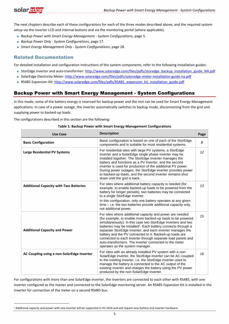
The configurations described in this section are the following:
Table 1: Backup Power with Smart Energy Management Configurations
Use Case Description Page
Basic Configuration Basic configuration is based on one of each of the StorEdge components and is suitable for most residential systems.
8
Large Residential PV Systems For residential sites with large PV systems, a StorEdge inverter and a SolarEdge single phase inverter may be installed together. The StorEdge inverter manages the battery and functions as a PV inverter, and the second inverter is used for production of the additional PV power. During power outages, the StorEdge inverter provides power to backed-up loads, and the second inverter remains shut down until the grid is back.
12
Additional Capacity with Two Batteries For sites where additional battery capacity is needed (for example, to enable backed-up loads to be powered from the battery for longer periods), two batteries may be connected to a single StorEdge inverter.
In this configuration, only one battery operates at any given time – i.e. the two batteries provide additional capacity only, not additional power.
13
Additional Capacity and Power
For sites where additional capacity and power are needed (for example, to enable more backed-up loads to be powered simultaneously). In this case two StorEdge inverters and two batteries may be installed1. Each battery connects through a separate StorEdge Inverter, and each inverter manages the battery and the PV connected to it. Backed-up loads are connected to each inverter through separate load panels and auto-transformers. The inverter connected to the meter operates as the system manager.
15
AC Coupling using a non-SolarEdge Inverter For sites with an already installed PV system with a non-SolarEdge inverter, the StorEdge inverter can be AC-coupled to the existing inverter, i.e. the StorEdge inverter used to manage the battery is connected to the AC output of the existing inverter and charges the battery using the PV power produced by the non-SolarEdge inverter.
16
For configurations with more than one SolarEdge inverter, the inverters are connected to each other with RS485, with one
inverter configured as the master and connected to the SolarEdge monitoring server. An RS485 Expansion Kit is installed in the
inverter for connection of the meter on a second RS485 bus.
1 Additional capacity and power with one inverter will be supported in H2 2016 and will require new battery and inverter hardware.

Backup Power with Smart Energy Management - System Configurations
6
System Connection
The following diagram illustrates the connection of the system components when using the basic configuration for backup
power with Smart Energy Management: one StorEdge inverter, one auto-transformer, one meter and one battery. For enlarged
segments of this diagram, refer to Appendix D – Detailed System Connection.
NOTE
Install the GFDI (Ground-Fault Detector Interrupter) in accordance with applicable local standards and directives.
Figure 4: Backup Power with Smart Energy Management - Basic Configuration
The following diagram shows the RS485 termination switch location on the inverter communication board (SW7) and on the
RS485 Expansion Kit (RS485 module).
Figure 5: RS485 termination switch location
L1 L2
MainDistribution Panel
CT
CT
CB
CB
15A CB
40A CB
CB 40A CB
Neutral bus-bar
L1_GridN_Grid
L2_Grid
20ACB
20ACB
20ACB
20ACB
Backed-up Loads Distribution Panel
BU_L1BU_L2
Connection to utility meter
25ACB
25ACB
BU_N
L1NL2
1" Conduit
Backup Neutral bus-bar
3 Meter AC [L1, L2, N], 12-16 AWG
8 ft twisted pair supplied with the CT Meter is required only for Smart Energy Managment
RS485 [A,B,G], 24 AWG (16-24 AWG), Shielded twisted pair, 600V insulated
3 Inverter AC Grid [L1, L2, N], 6 AWG (4-20 AWG)
3
3 Inverter AC Backup [L1, L2, N], 6 AWG (4-20 AWG)
Backup Panel Main
Breaker
Backed-up Loads Breakers
Type B for main circuit breakers
Battery HV DC+, 10 AWG (8-12 AWG), 600V insulatedBattery HV DC- , 10 AWG (8-12 AWG), 600V insulated
+-
V+V-
2 Thermal [V+, V-], 16AWG (12-16 AWG), Shielded pair, 600V insulated
PWRV+G
5 Control [V+, G, En, A+, B-], 24AWG (16-24 AWG), Shielded twisted pairs, 600V insulated
RTNEnA+B-
ENPN
Auto-transformer
3/4" Conduit
3/4" ConduitL1_A.T.N_A.T.
L2_A.T.T1T2
L1_A.T.N_A.T.L2_A.T.
T1T2
Auto-transformer AC [L1, L2, N], 8 AWG (6-20 AWG)3
2 Temp. sense [T1, T2], 24AWG (16-24 AWG), 600V insulated
RS485
SolarEdge Meter
A -B+G
NØL1ØL2ØL3
L1 CT
L2 CT
L3 CT
Main Breaker
To the backed-up loads
3/4" Conduit
PV DC+, 10 AWG (4-20 AWG), 600V insulated
PV DC- , 10 AWG (4-20 AWG), 600V insulated
22
StorEdge Inverter
BATIN
Fuses
12A
CBCB
CBCB
CBCB
CBCB
CBCB
CBCB
15A CBCB
NotesNote 1: Recommended Fuses in StorEdge Inverter: 12A 600VDC Quick-Acting, 10 x 38 mm Solar Midget Fuses
(Example: Littelfuse P/N 0SPF012)
Note 2: Auto-transformer connection: 6ft max Vertical mounting only (conduit connection from the bottom) Use 10 AWG wire for grounding
Note 3: Battery connection: 35ft max Distance larger than 5ft requires installation of external DC
safety switch on the battery side Control [B-,A+] must be twisted pair Note 4: Install type B 2-pole 25A main circuit breaker to ensure the 25A phase limit imbalance is maintained at all times.
Notes 1
Notes 2
Notes 3L1_BUL2_BU
N_BU
RS485-1 TerminationsMove up the left switch
Notes 41/2" Conduit
3/4" Conduit
Battery
Battery switches settings:
RS485
Backup Power with Smart Energy Management - System Configurations
7
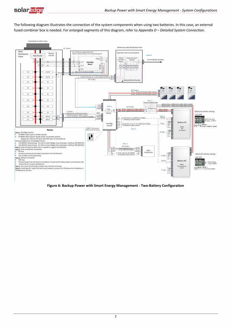
The following diagram illustrates the connection of the system components when using two batteries. In this case, an external
fused combiner box is needed. For enlarged segments of this diagram, refer to Appendix D – Detailed System Connection.
Figure 6: Backup Power with Smart Energy Management - Two-Battery Configuration
20ACB
20ACB
20ACB
20ACB
Backed-up Loads Distribution Panel
BU_L1BU_L2
25ACB
25ACB
BU_NBackup Neutral bus-bar
3 Meter AC [L1, L2, N], 12-16 AWG
3 Inverter AC Backup [L1, L2, N], 6 AWG (4-20 AWG)
Backup Panel Main
Breaker
Backed-up Loads Breakers
RS485
SolarEdge Meter
A -B+G
NØL1ØL2ØL3
L1 CT
L2 CT
L3 CT
To the backed-up loads
Notes 4
3/4" Conduit
L1 L2
MainDistribution Panel
CT
CT
RS485
CB
CB
15A CB
15A CBCB
40A CB
CB 40A CB
Neutral bus-bar
L1_GridN_Grid
L2_Grid
Connection to utility meter
L1NL2
3
3
1/2" Conduit
Main Breaker
3/4" Conduit
1" Conduit
RS485 [A,B,G], 24 AWG (16-24 AWG), Shielded twisted pair, 600V insulatedInverter AC Grid [L1, L2, N], 6 AWG (4-20 AWG)
PV DC+, 10 AWG (4-20 AWG), 600V insulated
PV DC- , 10 AWG (4-20 AWG), 600V insulated
Batt. HV DC+, 10AWG (10-12 AWG), 600V ins.Batt. HV DC-, 10AWG (10-12 AWG), 600V ins.
+-
V+V-
2
PWRV+G
5RTN
EnA+B-
ENPN
Thermal [V+, V-], 16AWG (12-16 AWG), Shielded pair, 600V insulated
Control [V+, G, En, A+, B-], 24AWG (16-24 AWG), Shielded pair, 600V insulated
+-
PWRRTNENPN
12A/600V fuses
Fused combiner box
1st port
2nd port
1st port
Thermal
Battery #1
RS485 Not
Terminated
Thermal
Battery HV DC+, 10AWG (10-12 AWG), 600V insulatedBattery HV DC- , 10AWG (10-12 AWG), 600V insulated
Battery HV DC+Battery HV DC-
PWR
ENPN
RTN
Battery #2
RS485Terminated and
biasedRTNENPN
2nd port
Battery #1 switches settings:
Battery #2 switches settings:
3/4" Conduit
StorEdge Inverter
Auto-transformer
3/4" ConduitL1_A.T.N_A.T.
L2_A.T.T1T2
Auto-transformer AC [L1, L2, N], 8 AWG (6-20 AWG)
3
2 Temp. sense [T1, T2], 24AWG (16-24 AWG), 600V insulated
L1_A.T.N_A.T.L2_A.T.
T1T2
L1_BUL2_BU
N_BU
CBCB
CBCB
CBCB
CBCB
CBCB
CBCB
NotesNote 1: StorEdge Inverter: SE7600A-USS0 supports double capacity SE7600A-USS2 supports double power and double capacity
- Replace the internal 12A fuses with 25A fuses for two batteriesRecommended Fuses in StorEdge Inverter: 12A 600VDC Quick-Acting, 10 x 38 mm Solar Midget Fuses (Example: Littelfuse P/N 0SPF012) 25A 600VDC Quick-Acting, 10 x 38 mm Solar Midget Fuses (Example: Littelfuse P/N 0SPF025)Note 2: External fused combiner box is needed to support two batteries. Note 3: Auto-transformer connection: 6ft max Vertical mounting only (conduit connection from the bottom) Use 10 AWG wire for groundingNote 4: Battery connection: 35ft max Distance larger than 5ft requires installation of external DC safety switch on the battery side Control [B-,A+] must be twisted pairNote 5: Use a twin-wire ferrules to daisy chain the thermal wiringNote 6: Install type B 2- pole 25A main circuit breaker to ensure the 25A phase limit imbalance is maintained at all times.
Note 1
Note 3
Note 4
Note 2
Note 5
RS485-1 TerminationsMove up the left switch
BATIN
Fuses
12A/25A
8 ft twisted pair supplied with the CT Meter is required only for Smart Energy Managment
Type B for main circuit breakers

Backup Power with Smart Energy Management - System Configurations
8
Basic Configuration
This configuration is based on one of each of the StorEdge components and is suitable for most residential systems.
Figure 7: Backup Power with Smart Energy Management - Basic configuration
► To configure the meter and the battery:
1 Terminate the battery connected on the RS485 bus:
2 Set the battery’s dip switches to ID 24: Move all dip switches to position 0 (to the right):
3 Make sure the wiring is connected according to the diagram above.
4 Upgrade the inverter firmware using the card supplied with the StorEdge Inverter. This will also configure the meter and the battery.
Backup Power with Smart Energy Management - System Configurations
9
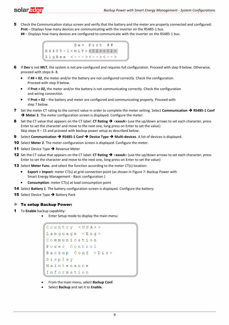
5 Check the Communication status screen and verify that the battery and the meter are properly connected and configured: Prot – Displays how many devices are communicating with the inverter on the RS485-1 bus. ## – Displays how many devices are configured to communicate with the inverter on the RS485-1 bus.
6 If Dev is not MLT, the system is not pre-configured and requires full configuration. Proceed with step 9 below. Otherwise, proceed with steps 6- 8.
If ## < 02, the meter and/or the battery are not configured correctly. Check the configuration. Proceed with step 9 below.
If Prot < 02, the meter and/or the battery is not communicating correctly. Check the configuration and wiring connection.
If Prot = 02 – the battery and meter are configured and communicating properly. Proceed with step 7 below.
7 Set the meter CT rating to the correct value in order to complete the meter setting. Select Communication RS485-1 Conf Meter 2. The meter configuration screen is displayed. Configure the meter:
8 Set the CT value that appears on the CT label: CT Rating <xxxxA> (use the up/down arrows to set each character, press Enter to set the character and move to the next one, long press on Enter to set the value) Skip steps 9 – 15 and proceed with backup power setup as described below.
9 Select Communication RS485-1 Conf Device Type Multi-devices. A list of devices is displayed.
10 Select Meter 2. The meter configuration screen is displayed. Configure the meter:
11 Select Device Type Revenue Meter
12 Set the CT value that appears on the CT label: CT Rating <xxxxA> (use the up/down arrows to set each character, press Enter to set the character and move to the next one, long press on Enter to set the value)
13 Select Meter Func. and select the function according to the meter CT(s) location:
Export + Import: meter CT(s) at grid connection point (as shown in Figure 7: Backup Power with Smart Energy Management - Basic configuration )
Consumption: meter CT(s) at load consumption point
14 Select Battery 1. The battery configuration screen is displayed. Configure the battery:
15 Select Device Type Battery Pack
► To setup Backup Power:
1 To Enable backup capability:
Enter Setup mode to display the main menu:
From the main menu, select Backup Conf.
Select Backup and set it to Enable.

Backup Power with Smart Energy Management - System Configurations
10
2 To set a minimum battery charge level, so that the battery will always have energy stored in case backup power is needed, do the following:
Select Power Control Energy Manager Storage Control. The following is displayed:
Select Backup RSVD and set the required level as percentage of the battery capacity. Set %PV according to user requirement.
3 After configuring the meter, the battery and backup power, proceed with Smart Energy Management application configuration for maximize self-consumption or for charge/discharge profile programming.
► To set up Maximize Self-consumption:
1 Select Power Control Energy Manager Energy Ctrl Max Self-Consume.
► To set up Charge/Discharge Profile Programming:
1 Select Power Control Energy Manager Energy Ctrl Time of Use.
2 Profile loading can be done remotely from the monitoring portal or locally from the inverter using a micro-SD card. Refer to Appendix A – Creating a Charge/Discharge Profile on page 33 for information on creating a charge/discharge profile file.
3 For remote loading:
In the monitoring portal, click the Admin icon and select the Energy Manager tab.
Select Set profile from server and from the drop down list select a profile. If no available profile is suitable, contact SolarEdge support.
Press Save and in the pop-up window select Yes to apply the profile. The profile will be loaded to the inverter upon next connection (normally within 5 minutes; if communications are down it will be uploaded when communications are restored)
NOTE
If the system is connected to the server with a GSM modem and with a SolarEdge data plan, loading can take place up
to 4 hours after applying from portal.
Figure 8: Profile programming screen
4 For local loading using a micro-SD card:
Select Energy Manager Set Calendar.
Insert the card with the profile file to the slot on the inverter communication board.
Select Load SD.
5 If the charge/discharge profile includes battery charge from the AC grid, this must be enabled, either from the inverter or as part of the profile file. Refer to the Appendix A – Creating a Charge/Discharge Profile for information on enabling this as part of the file.
NOTE
Use battery charge from AC grid only if permitted by local regulations.
► To enable from the inverter:
1 Select Energy Manager Storage Control.
Backup Power with Smart Energy Management - System Configurations
11
2 Select AC Charge Enable.
3 Select AC Charge Lim Limit Type and set one of the limits:
4 Set %PV to enter a limit as a percentage of year-to-date energy production.
5 Set kWh to enter a fixed annual energy limit.
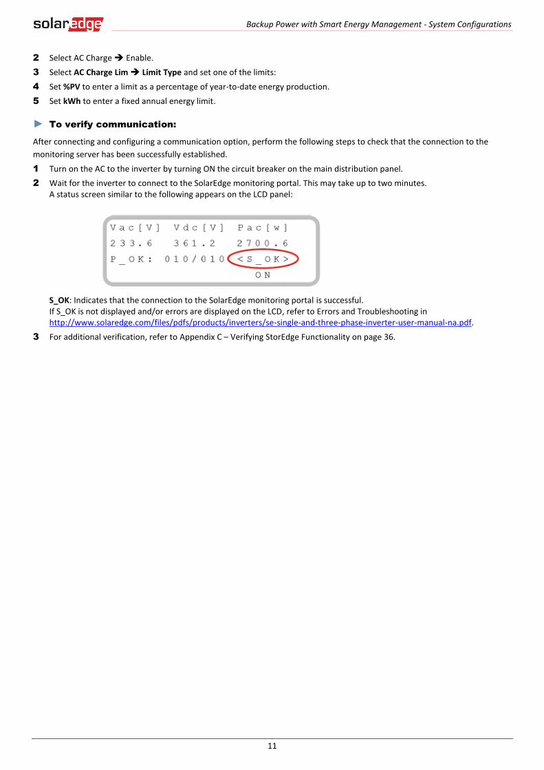
► To verify communication:
After connecting and configuring a communication option, perform the following steps to check that the connection to the
monitoring server has been successfully established.
1 Turn on the AC to the inverter by turning ON the circuit breaker on the main distribution panel.
2 Wait for the inverter to connect to the SolarEdge monitoring portal. This may take up to two minutes. A status screen similar to the following appears on the LCD panel:
S_OK: Indicates that the connection to the SolarEdge monitoring portal is successful. If S_OK is not displayed and/or errors are displayed on the LCD, refer to Errors and Troubleshooting in http://www.solaredge.com/files/pdfs/products/inverters/se-single-and-three-phase-inverter-user-manual-na.pdf.
3 For additional verification, refer to Appendix C – Verifying StorEdge Functionality on page 36.

Backup Power with Smart Energy Management - System Configurations
12
Large Residential PV Systems
For residential sites with large PV systems, a StorEdge inverter and a SolarEdge single phase inverter may be installed together.
The StorEdge inverter manages the battery and functions as a PV inverter, and the second inverter is used for production of the
additional PV power. During power outages, the StorEdge inverter provides power to backed-up loads, and the second inverter
remains shut down until the grid is back.
An RS485 Expansion Kit (available from SolarEdge) is installed in the inverter connected to the battery.
Figure 9: Backup Power with Smart Energy Management - Large residential PV systems
► To configure inverter RS485 Communication:
1 Install the RS485 Expansion Kit in the StorEdge inverter.
2 Connect the StorEdge inverter RS485 Expansion port the second inverter’s RS485-1 port using an RS485 twisted pair cable. Terminate both sides. From the StorEdge inverter:
3 Select Communication RS485-E Conf Enable. Press Enter to continue.
4 Select Protocol Master
5 Select Slave Detect. Verify that the inverter reports the correct number of slaves.
The second inverter does not require communication configuration.
► To configure the system:
1 Configure the meter, battery and backup power of the StorEdge inverter as described in the Basic Configuration on page 8.
2 Configure the second inverter as described in http://www.solaredge.com/files/pdfs/products/inverters/se-single-and-three-phase-inverter-user-manual-na.pdf.
► To set up Smart Energy Management:
After configuring the meter, battery and backup power, proceed with maximizing self-consumption or charge/discharge profile
programming on StorEdge inverter as described in the Basic Configuration on page 10.
► To verify communication:
Verify communication as described in the Basic Configuration on page 11.

Backup Power with Smart Energy Management - System Configurations
13
Additional Capacity with Two Batteries
For sites where additional battery capacity is needed (for example, to enable backed-up loads to be powered from the battery for longer periods), two batteries may be connected to a single StorEdge inverter.
In this configuration, only one battery operates at any given time – i.e. the two batteries provide additional capacity only, not additional power.
The DC connection of the two batteries to the StorEdge Inverter is done in parallel through an external fused combiner box (not provided by SolarEdge), with a fuse rating of 12A/600V.
The control and thermal connection of the second battery is daisy chained to that of the first battery.
Figure 10: Backup Power with Smart Energy Management - Additional capacity with two batteries
► To configure the system:
For battery RS485 settings:
Battery 1 is not terminated with ID: 24 and
Battery 2 is terminated with ID: 25
1 Terminate the battery which is connected last on the RS485 bus (battery 2), and make sure the other battery (battery 1) is not terminated:
Battery 1 - Unterminated battery: Battery 2 - Terminated battery:
Backup Power with Smart Energy Management - System Configurations
14
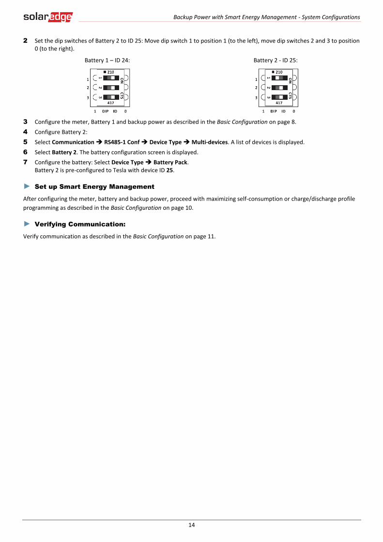
2 Set the dip switches of Battery 2 to ID 25: Move dip switch 1 to position 1 (to the left), move dip switches 2 and 3 to position 0 (to the right).
Battery 1 – ID 24: Battery 2 - ID 25:
3 Configure the meter, Battery 1 and backup power as described in the Basic Configuration on page 8.
4 Configure Battery 2:
5 Select Communication RS485-1 Conf Device Type Multi-devices. A list of devices is displayed.
6 Select Battery 2. The battery configuration screen is displayed.
7 Configure the battery: Select Device Type Battery Pack. Battery 2 is pre-configured to Tesla with device ID 25.
► Set up Smart Energy Management
After configuring the meter, battery and backup power, proceed with maximizing self-consumption or charge/discharge profile
programming as described in the Basic Configuration on page 10.
► Verifying Communication:
Verify communication as described in the Basic Configuration on page 11.
Backup Power with Smart Energy Management - System Configurations
15
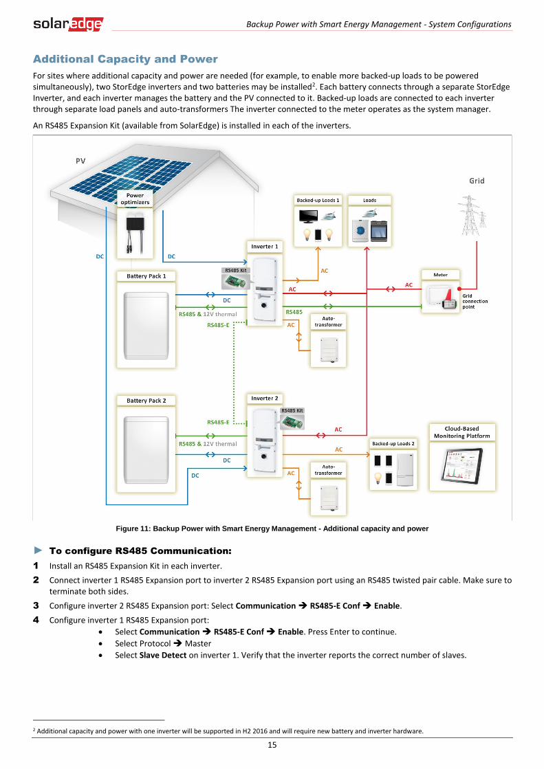
Additional Capacity and Power
For sites where additional capacity and power are needed (for example, to enable more backed-up loads to be powered simultaneously), two StorEdge inverters and two batteries may be installed2. Each battery connects through a separate StorEdge Inverter, and each inverter manages the battery and the PV connected to it. Backed-up loads are connected to each inverter through separate load panels and auto-transformers The inverter connected to the meter operates as the system manager.
An RS485 Expansion Kit (available from SolarEdge) is installed in each of the inverters.
Figure 11: Backup Power with Smart Energy Management - Additional capacity and power
► To configure RS485 Communication:
1 Install an RS485 Expansion Kit in each inverter.
2 Connect inverter 1 RS485 Expansion port to inverter 2 RS485 Expansion port using an RS485 twisted pair cable. Make sure to terminate both sides.
3 Configure inverter 2 RS485 Expansion port: Select Communication RS485-E Conf Enable.
4 Configure inverter 1 RS485 Expansion port:
Select Communication RS485-E Conf Enable. Press Enter to continue.
Select Protocol Master
Select Slave Detect on inverter 1. Verify that the inverter reports the correct number of slaves.
2 Additional capacity and power with one inverter will be supported in H2 2016 and will require new battery and inverter hardware.
Backup Power with Smart Energy Management - System Configurations
16
► To configure the system:
1 Configure the meter, battery and backup power of inverter 1 as described in the Basic Configuration on page 8.
2 Configure the battery and backup power of inverter 2 as described in the Basic Configuration on page 8.
3 Make sure that the meter is not configured on inverter 2:
Select Communication RS485-1 Conf Device Type Multi-devices.
Select Meter2 Meter Type None.
► To set up Smart Energy Management:
After configuring the meter, battery and backup power, proceed with maximizing self-consumption or charge/discharge profile
programming as described in the Basic Configuration on page 10. Repeat this configuration for each of the inverters.
► To verify communication:
Verify communication of both inverters as described in the Basic Configuration on page 11.
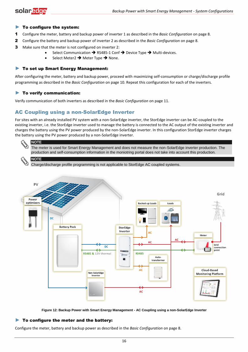
AC Coupling using a non-SolarEdge Inverter
For sites with an already installed PV system with a non-SolarEdge inverter, the StorEdge inverter can be AC-coupled to the existing inverter, i.e. the StorEdge inverter used to manage the battery is connected to the AC output of the existing inverter and charges the battery using the PV power produced by the non-SolarEdge inverter. In this configuration StorEdge inverter charges the battery using the PV power produced by a non-SolarEdge inverter.
NOTE
The meter is used for Smart Energy Management and does not measure the non-SolarEdge inverter production. The
production and self-consumption information in the moniotring portal does not take into account this production.
NOTE
Charge/discharge profile programming is not applicable to StorEdge AC coupled systems.
Figure 12: Backup Power with Smart Energy Management - AC Coupling using a non-SolarEdge Inverter
► To configure the meter and the battery:
Configure the meter, battery and backup power as described in the Basic Configuration on page 8.
Backup Power Only - System Configurations
17
► To set up Smart Energy Management:
After configuring the meter, battery and backup power, proceed with maximizing self-consumption as described in the Basic
Configuration on page 10.
► To verify communication:
Verify communication as described in the Basic Configuration on page 11.
Backup Power Only - System Configurations
In this mode, stored energy is used for backup power only. In case of a power outage, the inverter automatically switches to
backup mode, disconnecting from the grid and supplying power to backed-up loads.
A backup power only system can be upgraded to support Smart Energy Management applications by installing a SolarEdge
Electricity Meter and reconfiguring the system as described in Backup Power with Smart Energy Management - System
Configurations on page 5.
The configurations described in this section are the same as the configurations described above; system diagrams and
configuration details are for backup power only (for full descriptions of each configuration refer to Table 1: Backup Power with
Smart Energy Management Configurations page 5):
Basic Configuration
Large Residential PV Systems
Additional Capacity with Two Batteries
Additional Capacity and Power
AC Coupling using a non-SolarEdge Inverter
Error! Reference source not found.
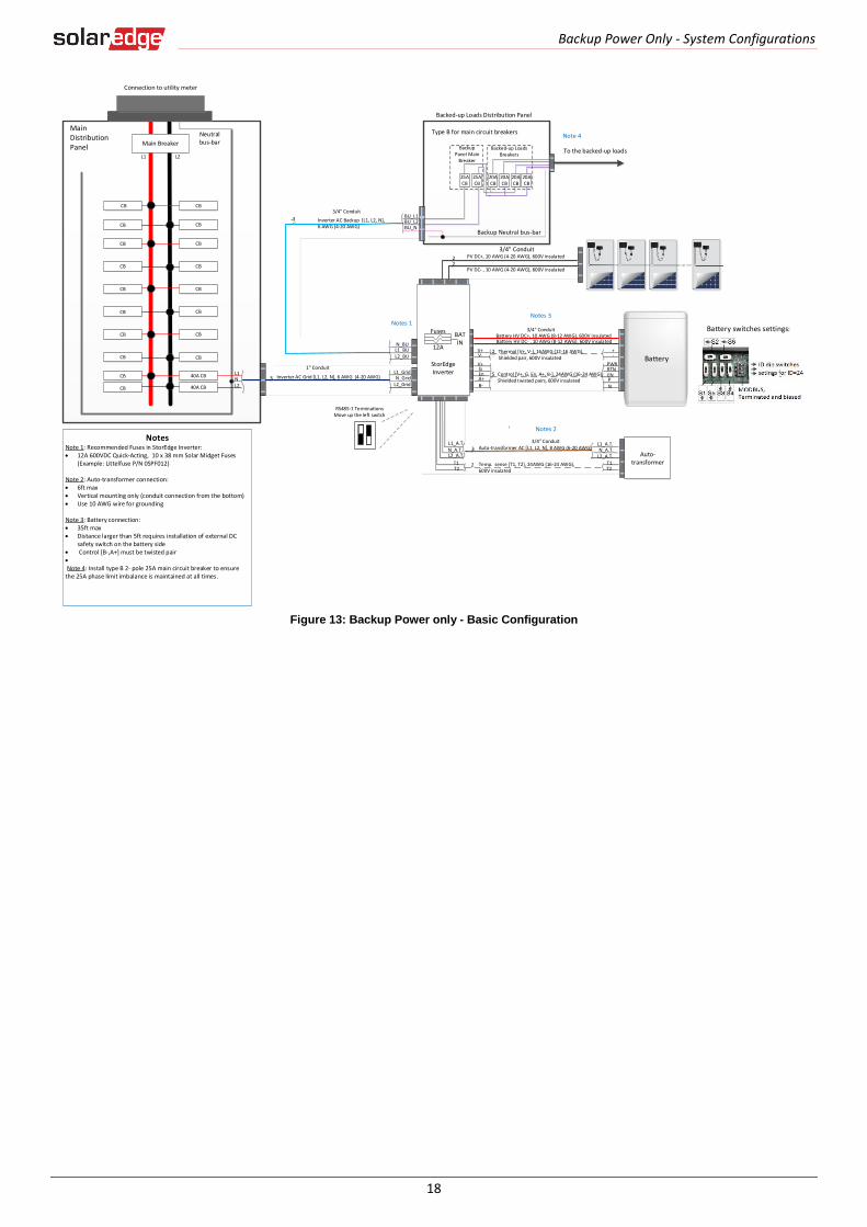
System Connection
The following diagram illustrates the connection of the system components when using the basic configuration for backup
power only: one StorEdge inverter, one auto-transformer and one battery. For enlarged segments of this diagram refer to
Appendix D – Detailed System Connection on page 46.
NOTE
Install the GFDI (Ground-Fault Detector Interrupter) in accordance with applicable local standards and directives.
Backup Power Only - System Configurations
18
Figure 13: Backup Power only - Basic Configuration
Battery
L1 L2
CB
MainDistribution Panel
CB
CB 40A CB
CB 40A CB
Neutral bus-bar
L1_GridN_Grid
L2_Grid
20ACB
20ACB
20ACB
20ACB
Backed-up Loads Distribution Panel
BU_L1BU_L2
Connection to utility meter
25ACB
25ACB
BU_N
L1NL2
1" Conduit
Backup Neutral bus-bar
3 Inverter AC Grid [L1, L2, N], 6 AWG (4-20 AWG)
3 Inverter AC Backup [L1, L2, N], 6 AWG (4-20 AWG)
Backup Panel Main
Breaker
Backed-up Loads Breakers
Battery HV DC+, 10 AWG (8-12 AWG), 600V insulatedBattery HV DC- , 10 AWG (8-12 AWG), 600V insulated
+-
V+V-
2 Thermal [V+, V-], 16AWG (12-16 AWG), Shielded pair, 600V insulated
PWRV+G
5 Control [V+, G, En, A+, B-], 24AWG (16-24 AWG), Shielded twisted pairs, 600V insulated
RTNEnA+B-
ENPN
Auto-transformer
3/4" Conduit
3/4" ConduitL1_A.T.N_A.T.
L2_A.T.T1T2
L1_A.T.N_A.T.L2_A.T.
T1T2
Auto-transformer AC [L1, L2, N], 8 AWG (6-20 AWG)3
2 Temp. sense [T1, T2], 24AWG (16-24 AWG), 600V insulated
Main BreakerTo the backed-up loads
PV DC+, 10 AWG (4-20 AWG), 600V insulated
PV DC- , 10 AWG (4-20 AWG), 600V insulated
22
StorEdge Inverter
BATIN
Fuses
12A
CBCB
CBCB
CBCB
CBCB
CBCB
CBCB
CBCB
NotesNote 1: Recommended Fuses in StorEdge Inverter: 12A 600VDC Quick-Acting, 10 x 38 mm Solar Midget Fuses
(Example: Littelfuse P/N 0SPF012)
Note 2: Auto-transformer connection: 6ft max Vertical mounting only (conduit connection from the bottom) Use 10 AWG wire for grounding
Note 3: Battery connection: 35ft max Distance larger than 5ft requires installation of external DC
safety switch on the battery side Control [B-,A+] must be twisted pair
Note 4: Install type B 2- pole 25A main circuit breaker to ensure the 25A phase limit imbalance is maintained at all times.
Notes 1
Notes 2
Notes 3
L1_BUL2_BU
N_BU
RS485-1 TerminationsMove up the left switch
Note 4
3/4" Conduit
3/4" Conduit
Battery switches settings:
Type B for main circuit breakers
Backup Power Only - System Configurations
19
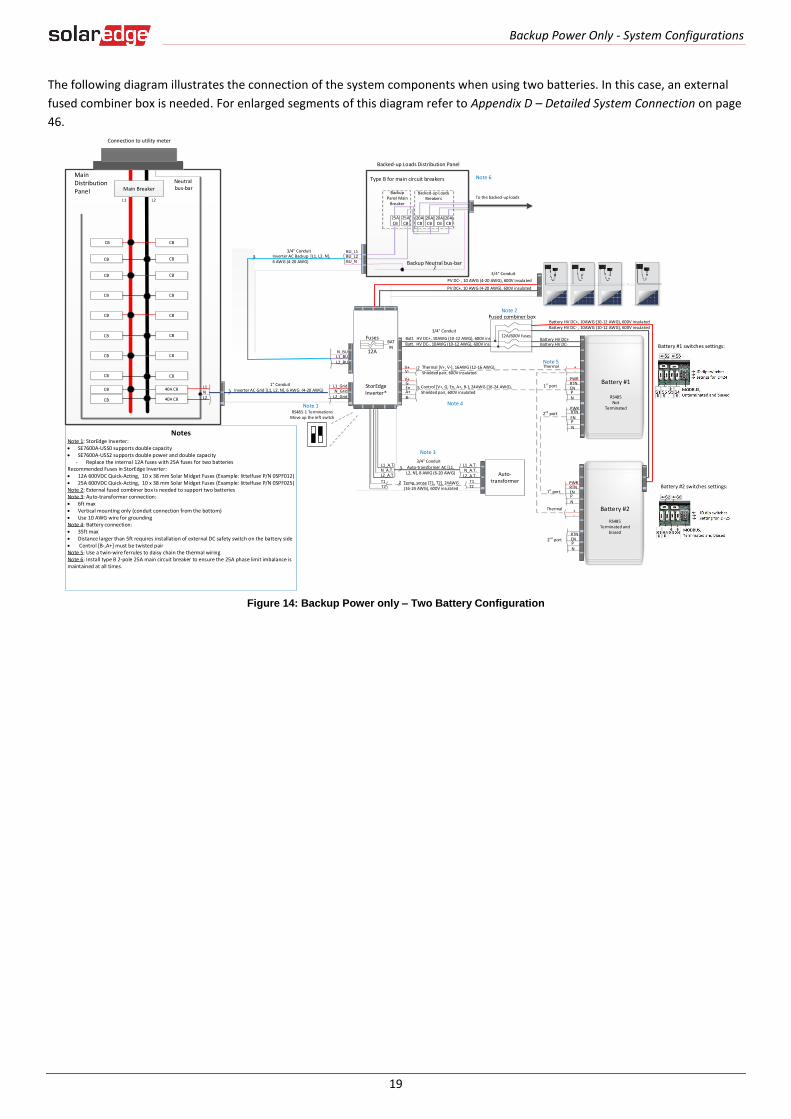
The following diagram illustrates the connection of the system components when using two batteries. In this case, an external
fused combiner box is needed. For enlarged segments of this diagram refer to Appendix D – Detailed System Connection on page
46.
Figure 14: Backup Power only – Two Battery Configuration
20ACB
20ACB
20ACB
20ACB
Backed-up Loads Distribution Panel
BU_L1BU_L2
25ACB
25ACB
BU_N Backup Neutral bus-bar
Backup Panel Main
Breaker
Backed-up Loads Breakers To the backed-up loads
L1 L2
MainDistribution Panel
CB
CB
CB
CBCB
40A CB
CB 40A CB
Neutral bus-bar
L1_GridN_Grid
L2_Grid
Connection to utility meter
L1NL2
3
Main Breaker
3/4" Conduit
2
1" ConduitInverter AC Grid [L1, L2, N], 6 AWG (4-20 AWG)
PV DC+, 10 AWG (4-20 AWG), 600V insulated
PV DC- , 10 AWG (4-20 AWG), 600V insulated
Batt. HV DC+, 10AWG (10-12 AWG), 600V ins.Batt. HV DC-, 10AWG (10-12 AWG), 600V ins.
+-
V+V-
2
PWRV+G
5RTN
EnA+B-
ENPN
Thermal [V+, V-], 16AWG (12-16 AWG), Shielded pair, 600V insulated
Control [V+, G, En, A+, B-], 24AWG (16-24 AWG), Shielded pair, 600V insulated
+-
PWRRTNENPN
12A/600V fuses
Fused combiner box
1st port
2nd port
1st port
Thermal
Battery #1
RS485 Not
Terminated
Thermal
Battery HV DC+, 10AWG (10-12 AWG), 600V insulatedBattery HV DC- , 10AWG (10-12 AWG), 600V insulated
Battery HV DC+Battery HV DC-
PWR
ENPN
RTN
Battery #2
RS485Terminated and
biasedRTNENPN
2nd port
Battery #1 switches settings:
Battery #2 switches settings:
3/4" Conduit
StorEdge Inverter*
BATIN
Fuses
12A
Auto-transformer
3/4" ConduitL1_A.T.N_A.T.
L2_A.T.T1T2
Auto-transformer AC [L1, L2, N], 8 AWG (6-20 AWG)
3
2 Temp. sense [T1, T2], 24AWG (16-24 AWG), 600V insulated
L1_A.T.N_A.T.L2_A.T.
T1T2
L1_BUL2_BU
N_BU
Inverter AC Backup [L1, L2, N], 6 AWG (4-20 AWG)
CBCB
CBCB
CBCB
CBCB
CBCB
CBCB
NotesNote 1: StorEdge Inverter: SE7600A-USS0 supports double capacity SE7600A-USS2 supports double power and double capacity
- Replace the internal 12A fuses with 25A fuses for two batteriesRecommended Fuses in StorEdge Inverter: 12A 600VDC Quick-Acting, 10 x 38 mm Solar Midget Fuses (Example: littelfuse P/N 0SPF012) 25A 600VDC Quick-Acting, 10 x 38 mm Solar Midget Fuses (Example: littelfuse P/N 0SPF025)Note 2: External fused combiner box is needed to support two batteriesNote 3: Auto-transformer connection: 6ft max Vertical mounting only (conduit connection from the bottom) Use 10 AWG wire for groundingNote 4: Battery connection: 35ft max Distance larger than 5ft requires installation of external DC safety switch on the battery side Control [B-,A+] must be twisted pairNote 5: Use a twin-wire ferrules to daisy chain the thermal wiringNote 6: Install type B 2-pole 25A main circuit breaker to ensure the 25A phase limit imbalance is maintained at all times.
Note 1
Note 3
Note 4
Note 2
Note 5
RS485-1 TerminationsMove up the left switch
Note 6
33/4" Conduit
Type B for main circuit breakers

Backup Power Only - System Configurations
20
Basic Configuration
This configuration is based on one of each of the StorEdge components, other than the SolarEdge Electricity Meter, and is
suitable for most residential systems.
Figure 15: Backup Power only - Basic configuration
► To configure the system:
1 Terminate the battery connected on the RS485 bus:
2 Set the battery’s dip switches to ID 24: Move all dip switches to position 0 (to the right):
3 Make sure the wiring is connected according to the diagram above.
4 Upgrade the inverter firmware using the card supplied with the StorEdge Inverter. This will also configure the battery.
5 Configure Meter 2 to None:
Select Communication RS485-1 Conf Device Type Multi-devices.
Select Meter2 Meter Type None.
6 Check the Communication status screen and verify that the battery is properly connected and configured:
7 If Dev is not MLT, the system is not pre-configured and requires full configuration. Proceed with step 10 below.
<01> <01>

Backup Power Only - System Configurations
21
8 If ## ≠ 01 or Prot ≠ 01, the battery and/or meter are not configured or communicating correctly. Check the configuration. Check the wiring connection. Proceed with step 10 below.
9 If ## = 01 and Prot = 01 – the battery is configured and communicating properly. Skip steps 10 to 13 below and proceed with set up backup power only as described below.
10 Select Communication RS485-1 Conf Device Type Multi-devices. A list of devices is displayed.
11 Configure Battery 1:
12 Select Battery 1. The battery configuration screen is displayed.
13 Configure the battery: Device Type Battery Pack
► To set up Backup Power Only:
1 Enter Setup mode to display the main menu.
2 From the main menu, select Power Control. A menu similar to the following is displayed:
3 Select Energy Manager. The following screen is displayed:
4 Select Energy Ctrl.
5 Select Backup only. The Energy Manager screen changes to display the following:
► Verifying Communication:
After connecting and configuring a communication option, perform the following steps to check that the connection to the
monitoring server has been successfully established.
1 Turn on the AC to the inverter by turning ON the circuit breaker on the main distribution panel.
2 Wait for the inverter to connect to the SolarEdge monitoring portal. This may take up to two minutes. A status screen similar to the following appears on the LCD panel:

Backup Power Only - System Configurations
22
S_OK: Indicates that the connection to the SolarEdge monitoring portal is successful. If S_OK is not displayed and/or errors are displayed on the LCD, refer to Errors and Troubleshooting in http://www.solaredge.com/files/pdfs/products/inverters/se-single-and-three-phase-inverter-user-manual-na.pdf.
3 For additional verification, refer to Appendix C – Verifying StorEdge Functionality on page 36.
Large Residential PV Systems
For residential sites with large PV systems, a StorEdge inverter and a SolarEdge single phase inverter may be installed together.
The StorEdge inverter manages the battery and functions as a PV inverter, and the second inverter is used for production of the
additional PV power. During power outages, the StorEdge inverter provides power to backed-up loads, and the second inverter
remains shut down until the grid is back.
An RS485 Expansion Kit (available from SolarEdge) is installed in the inverter connected to the battery.
Figure 16: Backup Power Only - Large residential PV systems
► To configure inverter RS485 communication:
1 Install the RS485 Expansion Kit in the inverter connected to the battery (SolarEdge inverter in Figure 16: Backup Power Only - Large residential PV systems).
2 Connect SolarEdge inverter RS485-1 port to SolarEdge standard inverter RS485-1 port using an RS485 twisted pair cable. Terminate both sides.
3 Select Communication RS485-E Conf Enable. Press Enter to continue.
4 Select Protocol Master.
5 Select Slave Detect. Verify that the inverter reports the correct number of slaves.
6 SolarEdge standard Inverter does not require communication configuration.
► To configure the system:
1 Configure the StorEdge inverter battery and backup power as described in the Basic Configuration page 20.
2 Configure the second SolarEdge inverter as described in http://www.solaredge.com/files/pdfs/products/inverters/se-single-and-three-phase-inverter-user-manual-na.pdf.

Backup Power Only - System Configurations
23
► To verify communication:
Verify SolarEdge inverter communication as described in the Basic Configuration on page 21.
Additional Capacity with Two Batteries
For sites where additional battery capacity is needed (for example, to enable backed-up loads to be powered from the batteries for longer periods), two batteries may be connected to a single StorEdge Inverter.
In this configuration, only one battery operates at any given time – i.e. the two batteries provide additional capacity only, not additional power.
The DC connection of the two batteries to the StorEdge Inverter is done in parallel through an external fused combiner box (not provided by SolarEdge), with a fuse rating of 12A/600V.
The control and thermal connection of the second battery is daisy chained to that of the first battery.
Figure 17: Backup Power Only - Additional capacity with two batteries
► Configure the System:
1 Terminate the battery which is connected last on the RS485 bus (battery 2), and make sure the other battery (battery 1) is not terminated:
Battery 1 - Unterminated battery: Battery 2 - Terminated battery:
Backup Power Only - System Configurations
24
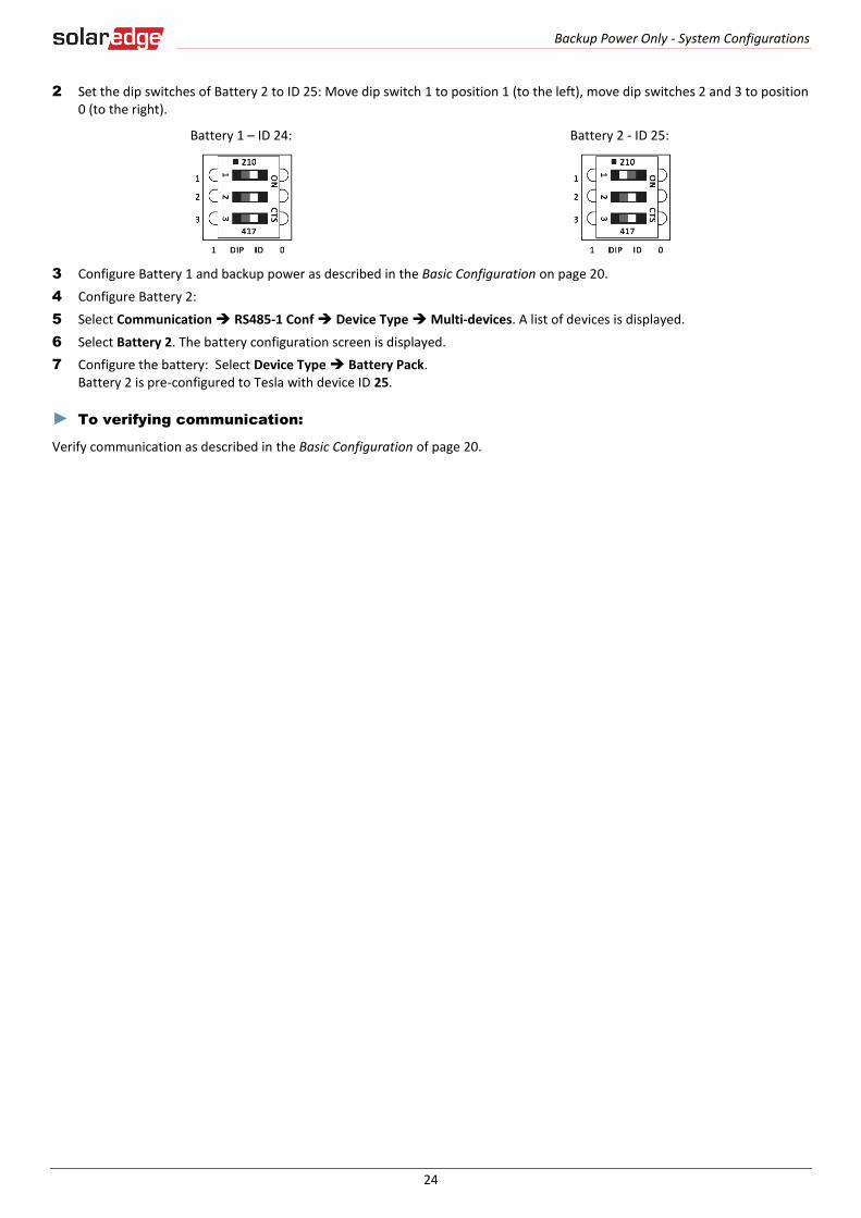
2 Set the dip switches of Battery 2 to ID 25: Move dip switch 1 to position 1 (to the left), move dip switches 2 and 3 to position 0 (to the right).
Battery 1 – ID 24: Battery 2 - ID 25:
3 Configure Battery 1 and backup power as described in the Basic Configuration on page 20.
4 Configure Battery 2:
5 Select Communication RS485-1 Conf Device Type Multi-devices. A list of devices is displayed.
6 Select Battery 2. The battery configuration screen is displayed.
7 Configure the battery: Select Device Type Battery Pack. Battery 2 is pre-configured to Tesla with device ID 25.
► To verifying communication:
Verify communication as described in the Basic Configuration of page 20.
Backup Power Only - System Configurations
25
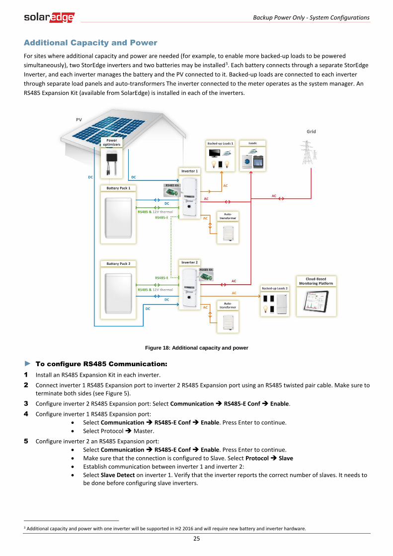
Additional Capacity and Power
For sites where additional capacity and power are needed (for example, to enable more backed-up loads to be powered
simultaneously), two StorEdge inverters and two batteries may be installed3. Each battery connects through a separate StorEdge
Inverter, and each inverter manages the battery and the PV connected to it. Backed-up loads are connected to each inverter
through separate load panels and auto-transformers The inverter connected to the meter operates as the system manager. An
RS485 Expansion Kit (available from SolarEdge) is installed in each of the inverters.
Figure 18: Additional capacity and power
► To configure RS485 Communication:
1 Install an RS485 Expansion Kit in each inverter.
2 Connect inverter 1 RS485 Expansion port to inverter 2 RS485 Expansion port using an RS485 twisted pair cable. Make sure to terminate both sides (see Figure 5).
3 Configure inverter 2 RS485 Expansion port: Select Communication RS485-E Conf Enable.
4 Configure inverter 1 RS485 Expansion port:
Select Communication RS485-E Conf Enable. Press Enter to continue.
Select Protocol Master.
5 Configure inverter 2 an RS485 Expansion port:
Select Communication RS485-E Conf Enable. Press Enter to continue.
Make sure that the connection is configured to Slave. Select Protocol Slave
Establish communication between inverter 1 and inverter 2:
Select Slave Detect on inverter 1. Verify that the inverter reports the correct number of slaves. It needs to be done before configuring slave inverters.
3 Additional capacity and power with one inverter will be supported in H2 2016 and will require new battery and inverter hardware.
Backup Power Only - System Configurations
26
► To configure the inverters:
Configure the battery and backup power of both inverters as described in the Basic Configuration on page 20..
► To verify communication:
Verify communication of both inverters as described in the Basic Configuration on page 21.
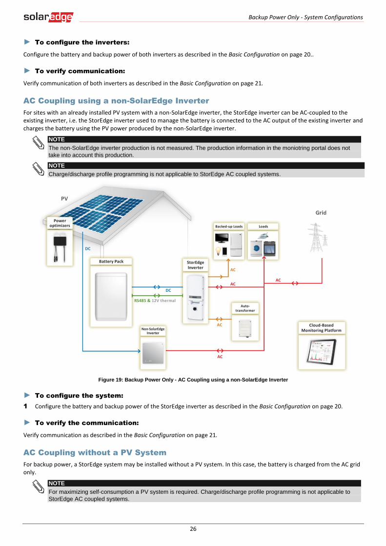
AC Coupling using a non-SolarEdge Inverter
For sites with an already installed PV system with a non-SolarEdge inverter, the StorEdge inverter can be AC-coupled to the existing inverter, i.e. the StorEdge inverter used to manage the battery is connected to the AC output of the existing inverter and charges the battery using the PV power produced by the non-SolarEdge inverter.
NOTE
The non-SolarEdge inverter production is not measured. The production information in the moniotring portal does not
take into account this production.
NOTE
Charge/discharge profile programming is not applicable to StorEdge AC coupled systems.
Figure 19: Backup Power Only - AC Coupling using a non-SolarEdge Inverter
► To configure the system:
1 Configure the battery and backup power of the StorEdge inverter as described in the Basic Configuration on page 20.
► To verify the communication:
Verify communication as described in the Basic Configuration on page 21.
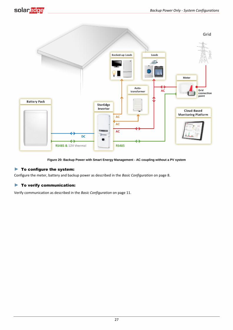
AC Coupling without a PV System
For backup power, a StorEdge system may be installed without a PV system. In this case, the battery is charged from the AC grid only.
NOTE
For maximizing self-consumption a PV system is required. Charge/discharge profile programming is not applicable to
StorEdge AC coupled systems.
Backup Power Only - System Configurations
27
Figure 20: Backup Power with Smart Energy Management - AC coupling without a PV system
► To configure the system:
Configure the meter, battery and backup power as described in the Basic Configuration on page 8.
► To verify communication:
Verify communication as described in the Basic Configuration on page 11.
Smart Energy Management Only - System Configurations
28
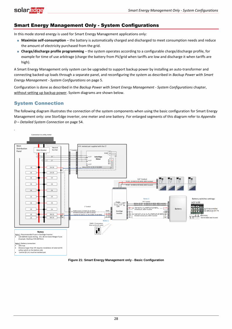
Smart Energy Management Only - System Configurations
In this mode stored energy is used for Smart Energy Management applications only:
Maximize self-consumption – the battery is automatically charged and discharged to meet consumption needs and reduce
the amount of electricity purchased from the grid.
Charge/discharge profile programming – the system operates according to a configurable charge/discharge profile, for
example for time of use arbitrage (charge the battery from PV/grid when tariffs are low and discharge it when tariffs are
high).
A Smart Energy Management only system can be upgraded to support backup power by installing an auto-transformer and
connecting backed-up loads through a separate panel, and reconfiguring the system as described in Backup Power with Smart
Energy Management - System Configurations on page 5.
Configuration is done as described in the Backup Power with Smart Energy Management - System Configurations chapter,
without setting up backup power. System diagrams are shown below.
System Connection
The following diagram illustrates the connection of the system components when using the basic configuration for Smart Energy
Management only: one StorEdge inverter, one meter and one battery. For enlarged segments of this diagram refer to Appendix
D – Detailed System Connection on page 54.
.
Figure 21: Smart Energy Management only - Basic Configuration
Battery
L1 L2
MainDistribution Panel
CT
CT
CB
CB
15A CB
40A CB
CB 40A CB
Neutral bus-bar
L1_GridN_Grid
L2_Grid
Connection to utility meter
L1NL2
1" Conduit
3 Meter AC [L1, L2, N], 12-16 AWG
8 ft twisted pair supplied with the CT
RS485 [A,B,G], 24 AWG (16-24 AWG), Shielded twisted pair, 600V insulated
3 Inverter AC Grid [L1, L2, N], 6 AWG (4-20 AWG)
3
1" Conduit
Battery HV DC+, 10 AWG (8-12 AWG), 600V insulatedBattery HV DC- , 10 AWG (8-12 AWG), 600V insulated
+-
V+V-
2 Thermal [V+, V-], 16AWG (12-16 AWG), Shielded pair, 600V insulated
PWRV+G
5 Control [V+, G, En, A+, B-], 24AWG (16-24 AWG), Shielded twisted pairs, 600V insulated
RTNEnA+B-
ENPN
3/4" Conduit
RS485
SolarEdge Meter
A -B+G
NØL1ØL2ØL3
L1 CT
L2 CT
L3 CT
Main Breaker
3/4" ConduitPV DC+, 10 AWG (4-20 AWG), 600V insulated
PV DC- , 10 AWG (4-20 AWG), 600V insulated
22
StorEdge Inverter
BATIN
Fuses
12A
CBCB
CBCB
CBCB
CBCB
CBCB
CBCB
15A CBCB
NotesNote 1: Recommended Fuses in StorEdge Inverter: 12A 600VDC Quick-Acting, 10 x 38 mm Solar Midget Fuses
(Example: littelfuse P/N 0SPF012)
Note 2: Battery connection: 35ft max Distance larger than 5ft requires installation of external DC
safety switch on the battery side Control [B-,A+] must be twisted pair
Notes 1
Notes 2
RS485
RS485-1 TerminationsMove up the left switch
Battery switches settings:
Smart Energy Management Only - System Configurations
29
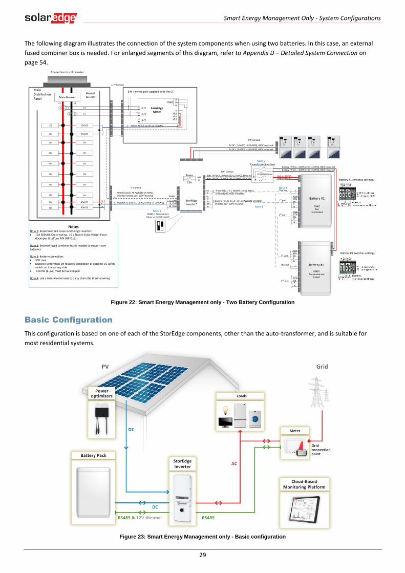
The following diagram illustrates the connection of the system components when using two batteries. In this case, an external
fused combiner box is needed. For enlarged segments of this diagram, refer to Appendix D – Detailed System Connection on
page 54.
Figure 22: Smart Energy Management only - Two Battery Configuration
Basic Configuration
This configuration is based on one of each of the StorEdge components, other than the auto-transformer, and is suitable for
most residential systems.
Figure 23: Smart Energy Management only - Basic configuration
3 Meter AC [L1, L2, N], 12-16 AWG
8 ft twisted pair supplied with the CT
RS485
SolarEdge Meter
A -B+G
NØL1ØL2ØL3
L1 CT
L2 CT
L3 CT
L1 L2
MainDistribution Panel
CT
CT
RS485
CB
CB
15A CB
15A CBCB
40A CB
CB 40A CB
Neutral bus-bar
L1_GridN_Grid
L2_Grid
Connection to utility meter
L1NL2
3
3
1/2" Conduit
Main Breaker
3/4" Conduit
1" Conduit
RS485 [A,B,G], 24 AWG (16-24 AWG), Shielded twisted pair, 600V insulated
Inverter AC Grid [L1, L2, N], 6 AWG (4-20 AWG)
PV DC+, 10 AWG (4-20 AWG), 600V insulated
PV DC- , 10 AWG (4-20 AWG), 600V insulated
Batt. HV DC+, 10AWG (10-12 AWG), 600V ins.Batt. HV DC-, 10AWG (10-12 AWG), 600V ins.
+-
V+V-
2
PWRV+G
5RTN
EnA+B-
ENPN
Thermal [V+, V-], 16AWG (12-16 AWG), Shielded pair, 600V insulated
Control [V+, G, En, A+, B-], 24AWG (16-24 AWG), Shielded pair, 600V insulated
+-
PWRRTNENPN
12A/600V fuses
Fused combiner box
1st port
2nd port
1st port
Thermal
Battery #1
RS485 Not
Terminated
Thermal
Battery HV DC+, 10AWG (10-12 AWG), 600V insulatedBattery HV DC- , 10AWG (10-12 AWG), 600V insulated
Battery HV DC+Battery HV DC-
PWR
ENPN
RTN
Battery #2
RS485Terminated and
biasedRTNENPN
2nd port
Battery #1 switches settings:
Battery #2 switches settings:
3/4" Conduit
StorEdge Inverter*
BATIN
Fuses
12A
CBCB
CBCB
CBCB
CBCB
CBCB
CBCB
NotesNote 1: Recommended Fuses in StorEdge Inverter: 12A 600VDC Quick-Acting, 10 x 38 mm Solar Midget Fuses
(Example: littelfuse P/N 0SPF012)
Note 2: External fused combiner box is needed to support two batteries
Note 3: Battery connection: 35ft max Distance larger than 5ft requires installation of external DC safety
switch on the battery side Control [B-,A+] must be twisted pair
Note 4: Use a twin-wire ferrules to daisy chain the thermal wiring
Note 1
Note 3
Note 2
Note 4
RS485-1 TerminationsMove up the left switch
Smart Energy Management Only - System Configurations
30
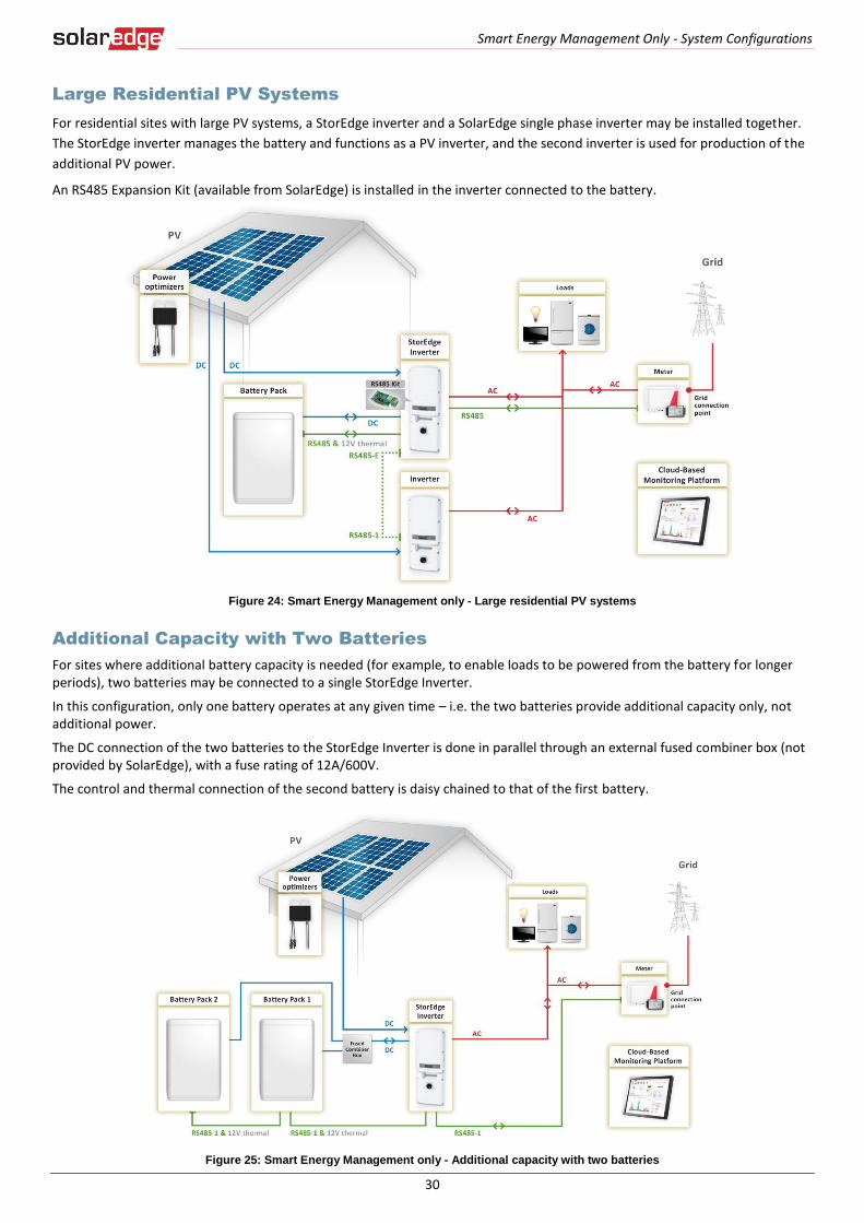
Large Residential PV Systems
For residential sites with large PV systems, a StorEdge inverter and a SolarEdge single phase inverter may be installed together.
The StorEdge inverter manages the battery and functions as a PV inverter, and the second inverter is used for production of the
additional PV power.
An RS485 Expansion Kit (available from SolarEdge) is installed in the inverter connected to the battery.
Figure 24: Smart Energy Management only - Large residential PV systems
Additional Capacity with Two Batteries
For sites where additional battery capacity is needed (for example, to enable loads to be powered from the battery for longer periods), two batteries may be connected to a single StorEdge Inverter.
In this configuration, only one battery operates at any given time – i.e. the two batteries provide additional capacity only, not additional power.
The DC connection of the two batteries to the StorEdge Inverter is done in parallel through an external fused combiner box (not provided by SolarEdge), with a fuse rating of 12A/600V.
The control and thermal connection of the second battery is daisy chained to that of the first battery.
Figure 25: Smart Energy Management only - Additional capacity with two batteries

Smart Energy Management Only - System Configurations
31
Additional Capacity and Power
For sites where additional capacity and power are needed (for example, to enable loads to be powered for longer periods
and/or to enable more loads to be powered simultaneously), two StorEdge inverters and two batteries may be installed4. Each
battery connects through a separate StorEdge Inverter, and each inverter manages the battery and the PV connected to it. The
inverter connected to the meter operates as the system manager. An RS485 Expansion Kit (available from SolarEdge) is installed
in each of the inverters.
The system can be upgraded to work in backup mode.
Figure 26: Smart Energy Management only - Additional capacity and power
4 Additional capacity and power with one inverter will be supported in H2 2016 and will require new battery and inverter hardware.
Smart Energy Management Only - System Configurations
32
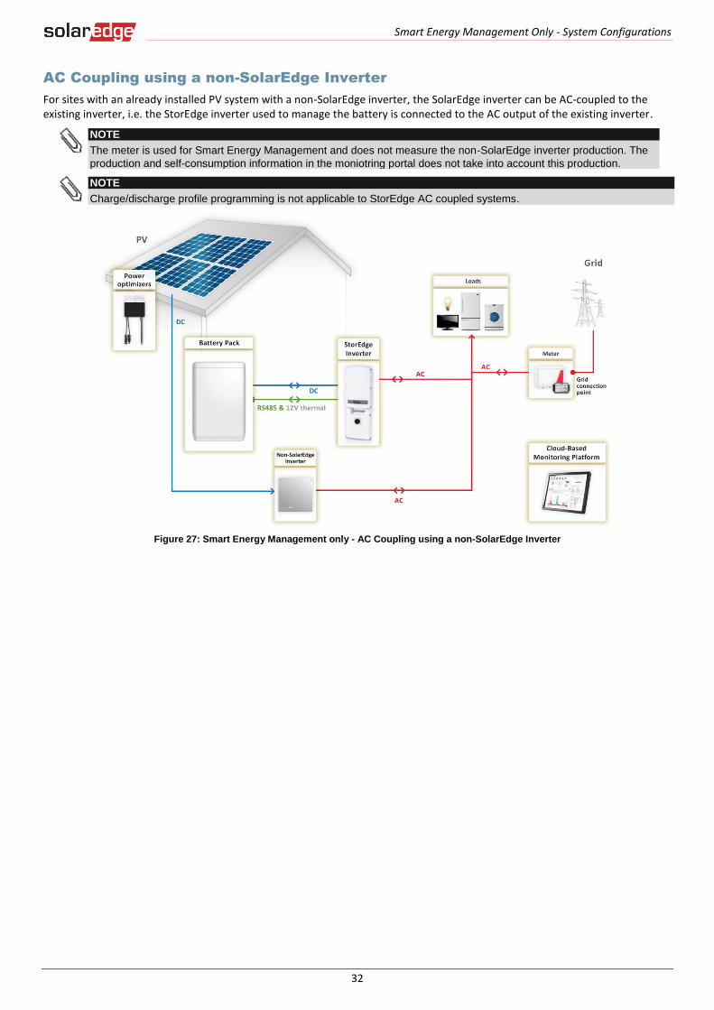
AC Coupling using a non-SolarEdge Inverter
For sites with an already installed PV system with a non-SolarEdge inverter, the SolarEdge inverter can be AC-coupled to the existing inverter, i.e. the StorEdge inverter used to manage the battery is connected to the AC output of the existing inverter.
NOTE
The meter is used for Smart Energy Management and does not measure the non-SolarEdge inverter production. The
production and self-consumption information in the moniotring portal does not take into account this production.
NOTE
Charge/discharge profile programming is not applicable to StorEdge AC coupled systems.
Figure 27: Smart Energy Management only - AC Coupling using a non-SolarEdge Inverter
Appendix A – Creating a Charge/Discharge Profile
33
Appendix A – Creating a Charge/Discharge Profile
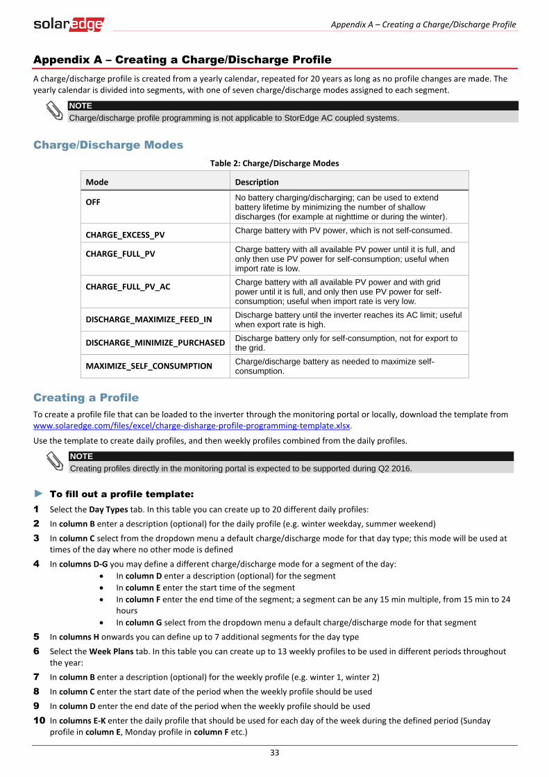
A charge/discharge profile is created from a yearly calendar, repeated for 20 years as long as no profile changes are made. The yearly calendar is divided into segments, with one of seven charge/discharge modes assigned to each segment.
NOTE
Charge/discharge profile programming is not applicable to StorEdge AC coupled systems.
Charge/Discharge Modes
Table 2: Charge/Discharge Modes
Mode Description
OFF No battery charging/discharging; can be used to extend battery lifetime by minimizing the number of shallow discharges (for example at nighttime or during the winter).
CHARGE_EXCESS_PV Charge battery with PV power, which is not self-consumed.
CHARGE_FULL_PV Charge battery with all available PV power until it is full, and only then use PV power for self-consumption; useful when import rate is low.
CHARGE_FULL_PV_AC Charge battery with all available PV power and with grid power until it is full, and only then use PV power for self-consumption; useful when import rate is very low.
DISCHARGE_MAXIMIZE_FEED_IN Discharge battery until the inverter reaches its AC limit; useful when export rate is high.
DISCHARGE_MINIMIZE_PURCHASED Discharge battery only for self-consumption, not for export to the grid.
MAXIMIZE_SELF_CONSUMPTION Charge/discharge battery as needed to maximize self-consumption.
Creating a Profile
To create a profile file that can be loaded to the inverter through the monitoring portal or locally, download the template from www.solaredge.com/files/excel/charge-disharge-profile-programming-template.xlsx.
Use the template to create daily profiles, and then weekly profiles combined from the daily profiles.
NOTE
Creating profiles directly in the monitoring portal is expected to be supported during Q2 2016.
► To fill out a profile template:
1 Select the Day Types tab. In this table you can create up to 20 different daily profiles:
2 In column B enter a description (optional) for the daily profile (e.g. winter weekday, summer weekend)
3 In column C select from the dropdown menu a default charge/discharge mode for that day type; this mode will be used at times of the day where no other mode is defined
4 In columns D-G you may define a different charge/discharge mode for a segment of the day:
In column D enter a description (optional) for the segment
In column E enter the start time of the segment
In column F enter the end time of the segment; a segment can be any 15 min multiple, from 15 min to 24 hours
In column G select from the dropdown menu a default charge/discharge mode for that segment
5 In columns H onwards you can define up to 7 additional segments for the day type
6 Select the Week Plans tab. In this table you can create up to 13 weekly profiles to be used in different periods throughout the year:
7 In column B enter a description (optional) for the weekly profile (e.g. winter 1, winter 2)
8 In column C enter the start date of the period when the weekly profile should be used
9 In column D enter the end date of the period when the weekly profile should be used
10 In columns E-K enter the daily profile that should be used for each day of the week during the defined period (Sunday profile in column E, Monday profile in column F etc.)
Appendix A – Creating a Charge/Discharge Profile
34
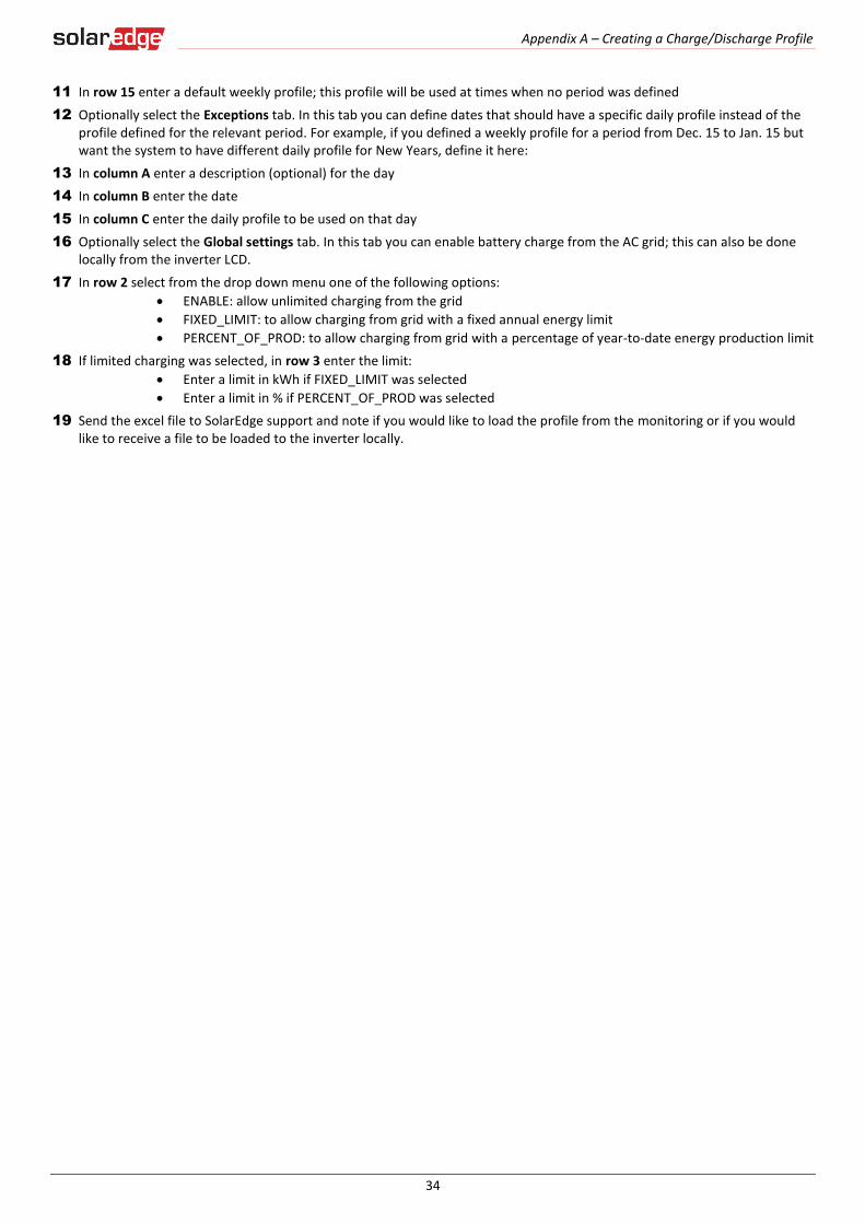
11 In row 15 enter a default weekly profile; this profile will be used at times when no period was defined
12 Optionally select the Exceptions tab. In this tab you can define dates that should have a specific daily profile instead of the profile defined for the relevant period. For example, if you defined a weekly profile for a period from Dec. 15 to Jan. 15 but want the system to have different daily profile for New Years, define it here:
13 In column A enter a description (optional) for the day
14 In column B enter the date
15 In column C enter the daily profile to be used on that day
16 Optionally select the Global settings tab. In this tab you can enable battery charge from the AC grid; this can also be done locally from the inverter LCD.
17 In row 2 select from the drop down menu one of the following options:
ENABLE: allow unlimited charging from the grid
FIXED_LIMIT: to allow charging from grid with a fixed annual energy limit
PERCENT_OF_PROD: to allow charging from grid with a percentage of year-to-date energy production limit
18 If limited charging was selected, in row 3 enter the limit:
Enter a limit in kWh if FIXED_LIMIT was selected
Enter a limit in % if PERCENT_OF_PROD was selected
19 Send the excel file to SolarEdge support and note if you would like to load the profile from the monitoring or if you would like to receive a file to be loaded to the inverter locally.

Appendix B - System Behavior Example
35
Appendix B - System Behavior Example
In this example the StorEdge system uses maximize self-consumption mode with zero export limit. The inverter is connected to
L1 and L2 in a split phase home. It supplies loads connected to L1 and to L2 load and exports excess PV power to the grid.
The produced PV power is 2kW, and there is 2kW load on L1 and a 1kW load on L2. The StorEdge system supplies 3kW to the
loads – including 1kW from the battery - and exports 0kW to the grid.
The meter measures 4.16A on L1 to the grid and senses 120VAC with positive phase between L1 and Neutral, therefore the
power import on L1 is 4.16A x 120V = 0.5kW. On L2 the meter measures also 4.16A from the grid and senses 120VAC with
negative phase between L2 and Neutral, therefore the power export on L2 is 4.16A x 120V = 0.5kW. Total export power is 0.5kW
- 0.5kW = 0kW. Due to the load imbalance between L1 and L2 there is an 8.33A current on the neutral wire between the home
and utility transformer.
Figure 28: Power Production Flow
Appendix C – Verifying StorEdge Functionality
36
Appendix C – Verifying StorEdge Functionality
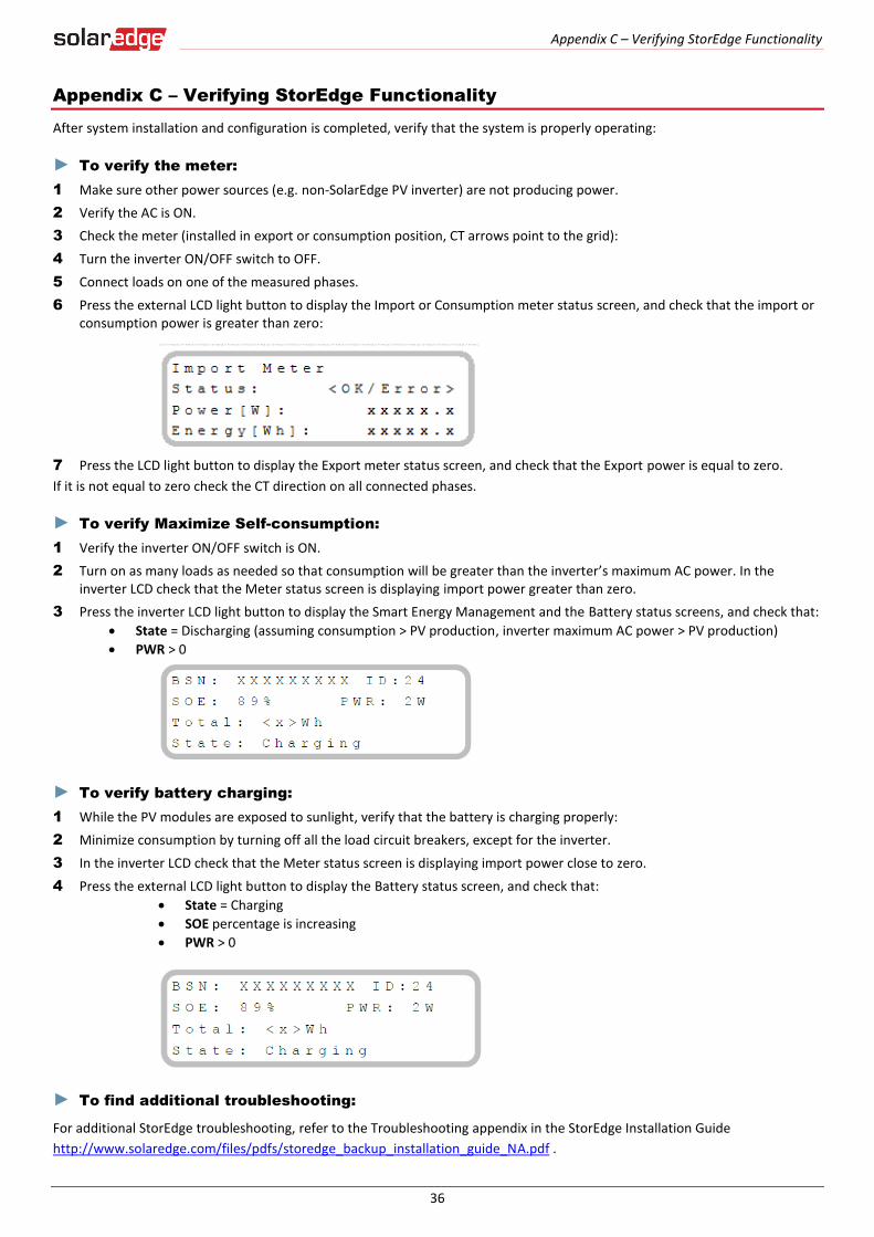
After system installation and configuration is completed, verify that the system is properly operating:
► To verify the meter:
1 Make sure other power sources (e.g. non-SolarEdge PV inverter) are not producing power.
2 Verify the AC is ON.
3 Check the meter (installed in export or consumption position, CT arrows point to the grid):
4 Turn the inverter ON/OFF switch to OFF.
5 Connect loads on one of the measured phases.
6 Press the external LCD light button to display the Import or Consumption meter status screen, and check that the import or consumption power is greater than zero:
7 Press the LCD light button to display the Export meter status screen, and check that the Export power is equal to zero.
If it is not equal to zero check the CT direction on all connected phases.
► To verify Maximize Self-consumption:
1 Verify the inverter ON/OFF switch is ON.
2 Turn on as many loads as needed so that consumption will be greater than the inverter’s maximum AC power. In the inverter LCD check that the Meter status screen is displaying import power greater than zero.
3 Press the inverter LCD light button to display the Smart Energy Management and the Battery status screens, and check that:
State = Discharging (assuming consumption > PV production, inverter maximum AC power > PV production)
PWR > 0
► To verify battery charging:
1 While the PV modules are exposed to sunlight, verify that the battery is charging properly:
2 Minimize consumption by turning off all the load circuit breakers, except for the inverter.
3 In the inverter LCD check that the Meter status screen is displaying import power close to zero.
4 Press the external LCD light button to display the Battery status screen, and check that:
State = Charging
SOE percentage is increasing
PWR > 0
► To find additional troubleshooting:
For additional StorEdge troubleshooting, refer to the Troubleshooting appendix in the StorEdge Installation Guide
http://www.solaredge.com/files/pdfs/storedge_backup_installation_guide_NA.pdf .

Appendix D – Detailed System Connection
37
Appendix D – Detailed System Connection
Backup Power with Smart Energy Management
Basic Configuration
The following diagram illustrates the connection of the system components when using the basic configuration for backup power with Smart Energy Management: one StorEdge inverter,
one auto-transformer, one meter and one battery. The next diagrams are enlarged segments of this diagram.

Appendix D – Detailed System Connection
38
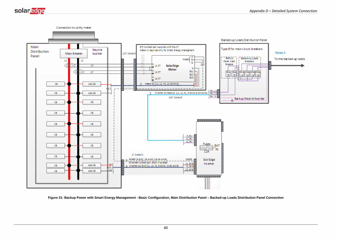
Figure 29: Backup Power with Smart Energy Management - Basic Configuration
L1 L2
MainDistribution Panel
CT
CT
CB
CB
15A CB
40A CB
CB 40A CB
Neutral bus-bar
L1_GridN_Grid
L2_Grid
20ACB
20ACB
20ACB
20ACB
Backed-up Loads Distribution Panel
BU_L1BU_L2
Connection to utility meter
25ACB
25ACB
BU_N
L1NL2
1" Conduit
Backup Neutral bus-bar
3 Meter AC [L1, L2, N], 12-16 AWG
8 ft twisted pair supplied with the CT Meter is required only for Smart Energy Managment
RS485 [A,B,G], 24 AWG (16-24 AWG), Shielded twisted pair, 600V insulated
3 Inverter AC Grid [L1, L2, N], 6 AWG (4-20 AWG)
3
3 Inverter AC Backup [L1, L2, N], 6 AWG (4-20 AWG)
Backup Panel Main
Breaker
Backed-up Loads Breakers
Type B for main circuit breakers
Battery HV DC+, 10 AWG (8-12 AWG), 600V insulatedBattery HV DC- , 10 AWG (8-12 AWG), 600V insulated
+-
V+V-
2 Thermal [V+, V-], 16AWG (12-16 AWG), Shielded pair, 600V insulated
PWRV+G
5 Control [V+, G, En, A+, B-], 24AWG (16-24 AWG), Shielded twisted pairs, 600V insulated
RTNEnA+B-
ENPN
Auto-transformer
3/4" Conduit
3/4" ConduitL1_A.T.N_A.T.
L2_A.T.T1T2
L1_A.T.N_A.T.L2_A.T.
T1T2
Auto-transformer AC [L1, L2, N], 8 AWG (6-20 AWG)3
2 Temp. sense [T1, T2], 24AWG (16-24 AWG), 600V insulated
RS485
SolarEdge Meter
A -B+G
NØL1ØL2ØL3
L1 CT
L2 CT
L3 CT
Main Breaker
To the backed-up loads
3/4" Conduit
PV DC+, 10 AWG (4-20 AWG), 600V insulated
PV DC- , 10 AWG (4-20 AWG), 600V insulated
22
StorEdge Inverter
BATIN
Fuses
12A
CBCB
CBCB
CBCB
CBCB
CBCB
CBCB
15A CBCB
NotesNote 1: Recommended Fuses in StorEdge Inverter: 12A 600VDC Quick-Acting, 10 x 38 mm Solar Midget Fuses
(Example: Littelfuse P/N 0SPF012)
Note 2: Auto-transformer connection: 6ft max Vertical mounting only (conduit connection from the bottom) Use 10 AWG wire for grounding
Note 3: Battery connection: 35ft max Distance larger than 5ft requires installation of external DC
safety switch on the battery side Control [B-,A+] must be twisted pair Note 4: Install type B 2-pole 25A main circuit breaker to ensure the 25A phase limit imbalance is maintained at all times.
Notes 1
Notes 2
Notes 3L1_BUL2_BU
N_BU
RS485-1 TerminationsMove up the left switch
Notes 41/2" Conduit
3/4" Conduit
Battery
Battery switches settings:
RS485

Appendix D – Detailed System Connection
39
Figure 30: Backup Power with Smart Energy Management - Basic Configuration, Battery - StorEdge Inverter Connection
Appendix D – Detailed System Connection
40
Figure 31: Backup Power with Smart Energy Management - Basic Configuration, Main Distribution Panel – Backed-up Loads Distribution Panel Connection
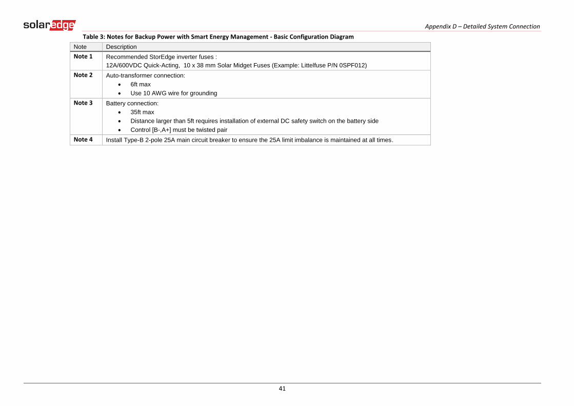
Appendix D – Detailed System Connection
41
Table 3: Notes for Backup Power with Smart Energy Management - Basic Configuration Diagram
Note Description
Note 1 Recommended StorEdge inverter fuses :
12A/600VDC Quick-Acting, 10 x 38 mm Solar Midget Fuses (Example: Littelfuse P/N 0SPF012)
Note 2 Auto-transformer connection:
6ft max
Use 10 AWG wire for grounding
Note 3 Battery connection:
35ft max
Distance larger than 5ft requires installation of external DC safety switch on the battery side
Control [B-,A+] must be twisted pair
Note 4 Install Type-B 2-pole 25A main circuit breaker to ensure the 25A limit imbalance is maintained at all times.
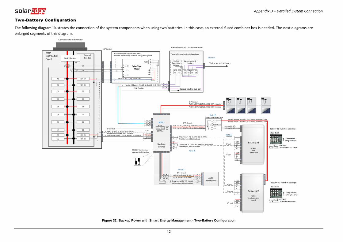
Appendix D – Detailed System Connection
42
Two-Battery Configuration
The following diagram illustrates the connection of the system components when using two batteries. In this case, an external fused combiner box is needed. The next diagrams are
enlarged segments of this diagram.
Figure 32: Backup Power with Smart Energy Management - Two-Battery Configuration
20ACB
20ACB
20ACB
20ACB
Backed-up Loads Distribution Panel
BU_L1BU_L2
25ACB
25ACB
BU_NBackup Neutral bus-bar
3 Meter AC [L1, L2, N], 12-16 AWG
3 Inverter AC Backup [L1, L2, N], 6 AWG (4-20 AWG)
Backup Panel Main
Breaker
Backed-up Loads Breakers
RS485
SolarEdge Meter
A -B+G
NØL1ØL2ØL3
L1 CT
L2 CT
L3 CT
To the backed-up loads
Notes 4
3/4" Conduit
L1 L2
MainDistribution Panel
CT
CT
RS485
CB
CB
15A CB
15A CBCB
40A CB
CB 40A CB
Neutral bus-bar
L1_GridN_Grid
L2_Grid
Connection to utility meter
L1NL2
3
3
1/2" Conduit
Main Breaker
3/4" Conduit
1" Conduit
RS485 [A,B,G], 24 AWG (16-24 AWG), Shielded twisted pair, 600V insulatedInverter AC Grid [L1, L2, N], 6 AWG (4-20 AWG)
PV DC+, 10 AWG (4-20 AWG), 600V insulated
PV DC- , 10 AWG (4-20 AWG), 600V insulated
Batt. HV DC+, 10AWG (10-12 AWG), 600V ins.Batt. HV DC-, 10AWG (10-12 AWG), 600V ins.
+-
V+V-
2
PWRV+G
5RTN
EnA+B-
ENPN
Thermal [V+, V-], 16AWG (12-16 AWG), Shielded pair, 600V insulated
Control [V+, G, En, A+, B-], 24AWG (16-24 AWG), Shielded pair, 600V insulated
+-
PWRRTNENPN
12A/600V fuses
Fused combiner box
1st port
2nd port
1st port
Thermal
Battery #1
RS485 Not
Terminated
Thermal
Battery HV DC+, 10AWG (10-12 AWG), 600V insulatedBattery HV DC- , 10AWG (10-12 AWG), 600V insulated
Battery HV DC+Battery HV DC-
PWR
ENPN
RTN
Battery #2
RS485Terminated and
biasedRTNENPN
2nd port
Battery #1 switches settings:
Battery #2 switches settings:
3/4" Conduit
StorEdge Inverter
Auto-transformer
3/4" ConduitL1_A.T.N_A.T.
L2_A.T.T1T2
Auto-transformer AC [L1, L2, N], 8 AWG (6-20 AWG)
3
2 Temp. sense [T1, T2], 24AWG (16-24 AWG), 600V insulated
L1_A.T.N_A.T.L2_A.T.
T1T2
L1_BUL2_BU
N_BU
CBCB
CBCB
CBCB
CBCB
CBCB
CBCB
NotesNote 1: StorEdge Inverter: SE7600A-USS0 supports double capacity SE7600A-USS2 supports double power and double capacity
- Replace the internal 12A fuses with 25A fuses for two batteriesRecommended Fuses in StorEdge Inverter: 12A 600VDC Quick-Acting, 10 x 38 mm Solar Midget Fuses (Example: Littelfuse P/N 0SPF012) 25A 600VDC Quick-Acting, 10 x 38 mm Solar Midget Fuses (Example: Littelfuse P/N 0SPF025)Note 2: External fused combiner box is needed to support two batteries. Note 3: Auto-transformer connection: 6ft max Vertical mounting only (conduit connection from the bottom) Use 10 AWG wire for groundingNote 4: Battery connection: 35ft max Distance larger than 5ft requires installation of external DC safety switch on the battery side Control [B-,A+] must be twisted pairNote 5: Use a twin-wire ferrules to daisy chain the thermal wiringNote 6: Install type B 2- pole 25A main circuit breaker to ensure the 25A phase limit imbalance is maintained at all times.
Note 1
Note 3
Note 4
Note 2
Note 5
RS485-1 TerminationsMove up the left switch
BATIN
Fuses
12A/25A
8 ft twisted pair supplied with the CT Meter is required only for Smart Energy Managment
Type B for main circuit breakers
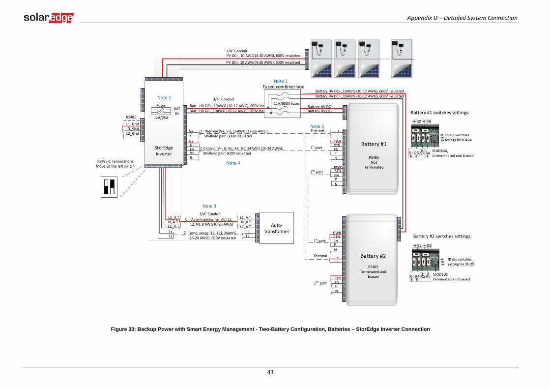
Appendix D – Detailed System Connection
43
Figure 33: Backup Power with Smart Energy Management - Two-Battery Configuration, Batteries – StorEdge Inverter Connection
20ACB
20ACB
20ACB
20ACB
Backed-up Loads Distribution Panel
BU_L1BU_L2
25ACB
25ACB
BU_NBackup Neutral bus-bar
3 Meter AC [L1, L2, N], 12-16 AWG
3 Inverter AC Backup [L1, L2, N], 6 AWG (4-20 AWG)
Backup Panel Main
Breaker
Backed-up Loads Breakers
RS485
SolarEdge Meter
A -B+G
NØL1ØL2ØL3
L1 CT
L2 CT
L3 CT
To the backed-up loads
Notes 4
3/4" Conduit
L1 L2
MainDistribution Panel
CT
CT
RS485
CB
CB
15A CB
15A CBCB
40A CB
CB 40A CB
Neutral bus-bar
L1_GridN_Grid
L2_Grid
Connection to utility meter
L1NL2
3
3
1/2" Conduit
Main Breaker
3/4" Conduit
1" Conduit
RS485 [A,B,G], 24 AWG (16-24 AWG), Shielded twisted pair, 600V insulatedInverter AC Grid [L1, L2, N], 6 AWG (4-20 AWG)
PV DC+, 10 AWG (4-20 AWG), 600V insulated
PV DC- , 10 AWG (4-20 AWG), 600V insulated
Batt. HV DC+, 10AWG (10-12 AWG), 600V ins.Batt. HV DC-, 10AWG (10-12 AWG), 600V ins.
+-
V+V-
2
PWRV+G
5RTN
EnA+B-
ENPN
Thermal [V+, V-], 16AWG (12-16 AWG), Shielded pair, 600V insulated
Control [V+, G, En, A+, B-], 24AWG (16-24 AWG), Shielded pair, 600V insulated
+-
PWRRTNENPN
12A/600V fuses
Fused combiner box
1st port
2nd port
1st port
Thermal
Battery #1
RS485 Not
Terminated
Thermal
Battery HV DC+, 10AWG (10-12 AWG), 600V insulatedBattery HV DC- , 10AWG (10-12 AWG), 600V insulated
Battery HV DC+Battery HV DC-
PWR
ENPN
RTN
Battery #2
RS485Terminated and
biasedRTNENPN
2nd port
Battery #1 switches settings:
Battery #2 switches settings:
3/4" Conduit
StorEdge Inverter
Auto-transformer
3/4" ConduitL1_A.T.N_A.T.
L2_A.T.T1T2
Auto-transformer AC [L1, L2, N], 8 AWG (6-20 AWG)
3
2 Temp. sense [T1, T2], 24AWG (16-24 AWG), 600V insulated
L1_A.T.N_A.T.L2_A.T.
T1T2
L1_BUL2_BU
N_BU
CBCB
CBCB
CBCB
CBCB
CBCB
CBCB
NotesNote 1: StorEdge Inverter: SE7600A-USS0 supports double capacity SE7600A-USS2 supports double power and double capacity
- Replace the internal 12A fuses with 25A fuses for two batteriesRecommended Fuses in StorEdge Inverter: 12A 600VDC Quick-Acting, 10 x 38 mm Solar Midget Fuses (Example: Littelfuse P/N 0SPF012) 25A 600VDC Quick-Acting, 10 x 38 mm Solar Midget Fuses (Example: Littelfuse P/N 0SPF025)Note 2: External fused combiner box is needed to support two batteries. Note 3: Auto-transformer connection: 6ft max Vertical mounting only (conduit connection from the bottom) Use 10 AWG wire for groundingNote 4: Battery connection: 35ft max Distance larger than 5ft requires installation of external DC safety switch on the battery side Control [B-,A+] must be twisted pairNote 5: Use a twin-wire ferrules to daisy chain the thermal wiringNote 6: Install type B 2- pole 25A main circuit breaker to ensure the 25A phase limit imbalance is maintained at all times.
Note 1
Note 3
Note 4
Note 2
Note 5
RS485-1 TerminationsMove up the left switch
BATIN
Fuses
12A/25A
8 ft twisted pair supplied with the CT Meter is required only for Smart Energy Managment
Type B for main circuit breakers
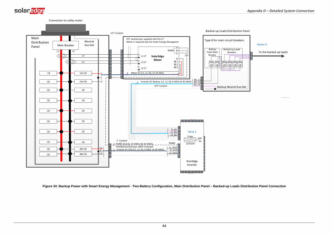
Appendix D – Detailed System Connection
44
Figure 34: Backup Power with Smart Energy Management - Two-Battery Configuration, Main Distribution Panel – Backed-up Loads Distribution Panel Connection
20ACB
20ACB
20ACB
20ACB
Backed-up Loads Distribution Panel
BU_L1BU_L2
25ACB
25ACB
BU_NBackup Neutral bus-bar
3 Meter AC [L1, L2, N], 12-16 AWG
3 Inverter AC Backup [L1, L2, N], 6 AWG (4-20 AWG)
Backup Panel Main
Breaker
Backed-up Loads Breakers
RS485
SolarEdge Meter
A -B+G
NØL1ØL2ØL3
L1 CT
L2 CT
L3 CT
To the backed-up loads
Notes 4
3/4" Conduit
L1 L2
MainDistribution Panel
CT
CT
RS485
CB
CB
15A CB
15A CBCB
40A CB
CB 40A CB
Neutral bus-bar
L1_GridN_Grid
L2_Grid
Connection to utility meter
L1NL2
3
3
1/2" Conduit
Main Breaker
3/4" Conduit
1" Conduit
RS485 [A,B,G], 24 AWG (16-24 AWG), Shielded twisted pair, 600V insulatedInverter AC Grid [L1, L2, N], 6 AWG (4-20 AWG)
PV DC+, 10 AWG (4-20 AWG), 600V insulated
PV DC- , 10 AWG (4-20 AWG), 600V insulated
Batt. HV DC+, 10AWG (10-12 AWG), 600V ins.Batt. HV DC-, 10AWG (10-12 AWG), 600V ins.
+-
V+V-
2
PWRV+G
5RTN
EnA+B-
ENPN
Thermal [V+, V-], 16AWG (12-16 AWG), Shielded pair, 600V insulated
Control [V+, G, En, A+, B-], 24AWG (16-24 AWG), Shielded pair, 600V insulated
+-
PWRRTNENPN
12A/600V fuses
Fused combiner box
1st port
2nd port
1st port
Thermal
Battery #1
RS485 Not
Terminated
Thermal
Battery HV DC+, 10AWG (10-12 AWG), 600V insulatedBattery HV DC- , 10AWG (10-12 AWG), 600V insulated
Battery HV DC+Battery HV DC-
PWR
ENPN
RTN
Battery #2
RS485Terminated and
biasedRTNENPN
2nd port
Battery #1 switches settings:
Battery #2 switches settings:
3/4" Conduit
StorEdge Inverter
Auto-transformer
3/4" ConduitL1_A.T.N_A.T.
L2_A.T.T1T2
Auto-transformer AC [L1, L2, N], 8 AWG (6-20 AWG)
3
2 Temp. sense [T1, T2], 24AWG (16-24 AWG), 600V insulated
L1_A.T.N_A.T.L2_A.T.
T1T2
L1_BUL2_BU
N_BU
CBCB
CBCB
CBCB
CBCB
CBCB
CBCB
NotesNote 1: StorEdge Inverter: SE7600A-USS0 supports double capacity SE7600A-USS2 supports double power and double capacity
- Replace the internal 12A fuses with 25A fuses for two batteriesRecommended Fuses in StorEdge Inverter: 12A 600VDC Quick-Acting, 10 x 38 mm Solar Midget Fuses (Example: Littelfuse P/N 0SPF012) 25A 600VDC Quick-Acting, 10 x 38 mm Solar Midget Fuses (Example: Littelfuse P/N 0SPF025)Note 2: External fused combiner box is needed to support two batteries. Note 3: Auto-transformer connection: 6ft max Vertical mounting only (conduit connection from the bottom) Use 10 AWG wire for groundingNote 4: Battery connection: 35ft max Distance larger than 5ft requires installation of external DC safety switch on the battery side Control [B-,A+] must be twisted pairNote 5: Use a twin-wire ferrules to daisy chain the thermal wiringNote 6: Install type B 2- pole 25A main circuit breaker to ensure the 25A phase limit imbalance is maintained at all times.
Note 1
Note 3
Note 4
Note 2
Note 5
RS485-1 TerminationsMove up the left switch
BATIN
Fuses
12A/25A
8 ft twisted pair supplied with the CT Meter is required only for Smart Energy Managment
Type B for main circuit breakers

Appendix D – Detailed System Connection
45
Table 4: Notes for Backup Power with Smart Energy Management - Two-Battery Configuration Diagram
Note Description
Note 1 Recommended StorEdge inverter fuses :
12A 600VDC Quick-Acting, 10 x 38 mm Solar Midget Fuses (Example: Littelfuse P/N 0SPF012)
Note 2 An external fused combiner box is needed to support two batteries
Note 3 Auto-transformer connection:
6ft max
Use 10 AWG wire for grounding
Note 4 Battery connection:
35ft max
Distance larger than 5ft requires installation of external DC safety switch on the battery side
Control [B-,A+] must be twisted pair
Note 5 Use a twin-wire ferrules to daisy chain the thermal wiring
Note 6 Install Type-B 2-pole 25A main circuit breaker to ensure the 25A limit imbalance is maintained at all times.
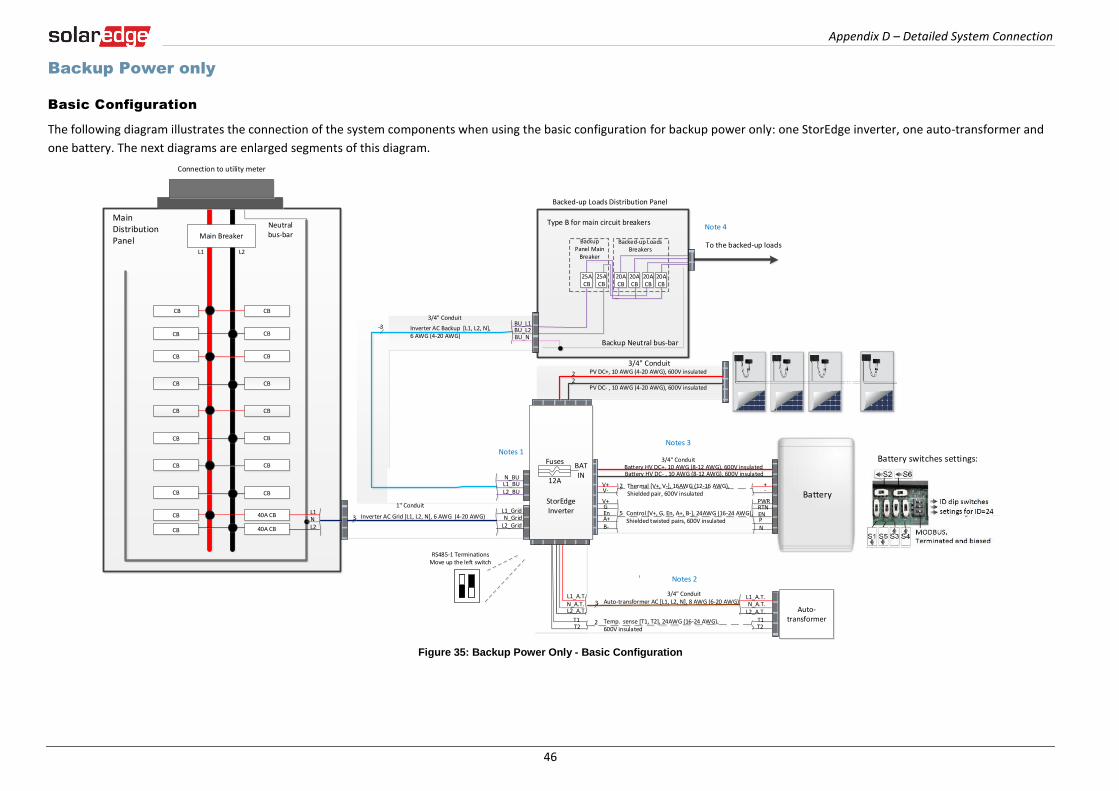
Appendix D – Detailed System Connection
46
Backup Power only
Basic Configuration
The following diagram illustrates the connection of the system components when using the basic configuration for backup power only: one StorEdge inverter, one auto-transformer and
one battery. The next diagrams are enlarged segments of this diagram.
Figure 35: Backup Power Only - Basic Configuration
Battery
L1 L2
CB
MainDistribution Panel
CB
CB 40A CB
CB 40A CB
Neutral bus-bar
L1_GridN_Grid
L2_Grid
20ACB
20ACB
20ACB
20ACB
Backed-up Loads Distribution Panel
BU_L1BU_L2
Connection to utility meter
25ACB
25ACB
BU_N
L1NL2
1" Conduit
Backup Neutral bus-bar
3 Inverter AC Grid [L1, L2, N], 6 AWG (4-20 AWG)
3 Inverter AC Backup [L1, L2, N], 6 AWG (4-20 AWG)
Backup Panel Main
Breaker
Backed-up Loads Breakers
Battery HV DC+, 10 AWG (8-12 AWG), 600V insulatedBattery HV DC- , 10 AWG (8-12 AWG), 600V insulated
+-
V+V-
2 Thermal [V+, V-], 16AWG (12-16 AWG), Shielded pair, 600V insulated
PWRV+G
5 Control [V+, G, En, A+, B-], 24AWG (16-24 AWG), Shielded twisted pairs, 600V insulated
RTNEnA+B-
ENPN
Auto-transformer
3/4" Conduit
3/4" ConduitL1_A.T.N_A.T.
L2_A.T.T1T2
L1_A.T.N_A.T.L2_A.T.
T1T2
Auto-transformer AC [L1, L2, N], 8 AWG (6-20 AWG)3
2 Temp. sense [T1, T2], 24AWG (16-24 AWG), 600V insulated
Main BreakerTo the backed-up loads
PV DC+, 10 AWG (4-20 AWG), 600V insulated
PV DC- , 10 AWG (4-20 AWG), 600V insulated
22
StorEdge Inverter
BATIN
Fuses
12A
CBCB
CBCB
CBCB
CBCB
CBCB
CBCB
CBCB
NotesNote 1: Recommended Fuses in StorEdge Inverter: 12A 600VDC Quick-Acting, 10 x 38 mm Solar Midget Fuses
(Example: Littelfuse P/N 0SPF012)
Note 2: Auto-transformer connection: 6ft max Vertical mounting only (conduit connection from the bottom) Use 10 AWG wire for grounding
Note 3: Battery connection: 35ft max Distance larger than 5ft requires installation of external DC
safety switch on the battery side Control [B-,A+] must be twisted pair
Note 4: Install type B 2- pole 25A main circuit breaker to ensure the 25A phase limit imbalance is maintained at all times.
Notes 1
Notes 2
Notes 3
L1_BUL2_BU
N_BU
RS485-1 TerminationsMove up the left switch
Note 4
3/4" Conduit
3/4" Conduit
Battery switches settings:
Type B for main circuit breakers

Appendix D – Detailed System Connection
47
Figure 36: Backup Power Only - Basic Configuration, StorEdge inverter - Battery Connection
Battery
L1 L2
CB
MainDistribution Panel
CB
CB 40A CB
CB 40A CB
Neutral bus-bar
L1_GridN_Grid
L2_Grid
20ACB
20ACB
20ACB
20ACB
Backed-up Loads Distribution Panel
BU_L1BU_L2
Connection to utility meter
25ACB
25ACB
BU_N
L1NL2
1" Conduit
Backup Neutral bus-bar
3 Inverter AC Grid [L1, L2, N], 6 AWG (4-20 AWG)
3 Inverter AC Backup [L1, L2, N], 6 AWG (4-20 AWG)
Backup Panel Main
Breaker
Backed-up Loads Breakers
Battery HV DC+, 10 AWG (8-12 AWG), 600V insulatedBattery HV DC- , 10 AWG (8-12 AWG), 600V insulated
+-
V+V-
2 Thermal [V+, V-], 16AWG (12-16 AWG), Shielded pair, 600V insulated
PWRV+G
5 Control [V+, G, En, A+, B-], 24AWG (16-24 AWG), Shielded twisted pairs, 600V insulated
RTNEnA+B-
ENPN
Auto-transformer
3/4" Conduit
3/4" ConduitL1_A.T.N_A.T.
L2_A.T.T1T2
L1_A.T.N_A.T.L2_A.T.
T1T2
Auto-transformer AC [L1, L2, N], 8 AWG (6-20 AWG)3
2 Temp. sense [T1, T2], 24AWG (16-24 AWG), 600V insulated
Main BreakerTo the backed-up loads
PV DC+, 10 AWG (4-20 AWG), 600V insulated
PV DC- , 10 AWG (4-20 AWG), 600V insulated
22
StorEdge Inverter
BATIN
Fuses
12A
CBCB
CBCB
CBCB
CBCB
CBCB
CBCB
CBCB
NotesNote 1: Recommended Fuses in StorEdge Inverter: 12A 600VDC Quick-Acting, 10 x 38 mm Solar Midget Fuses
(Example: Littelfuse P/N 0SPF012)
Note 2: Auto-transformer connection: 6ft max Vertical mounting only (conduit connection from the bottom) Use 10 AWG wire for grounding
Note 3: Battery connection: 35ft max Distance larger than 5ft requires installation of external DC
safety switch on the battery side Control [B-,A+] must be twisted pair
Note 4: Install type B 2- pole 25A main circuit breaker to ensure the 25A phase limit imbalance is maintained at all times.
Notes 1
Notes 2
Notes 3
L1_BUL2_BU
N_BU
RS485-1 TerminationsMove up the left switch
Note 4
3/4" Conduit
3/4" Conduit
Battery switches settings:
Type B for main circuit breakers

Appendix D – Detailed System Connection
48
Figure 37: Backup Power Only - Basic Configuration, Distribution Panel – Backed-up Loads Panel Connection
Battery
L1 L2
CB
MainDistribution Panel
CB
CB 40A CB
CB 40A CB
Neutral bus-bar
L1_GridN_Grid
L2_Grid
20ACB
20ACB
20ACB
20ACB
Backed-up Loads Distribution Panel
BU_L1BU_L2
Connection to utility meter
25ACB
25ACB
BU_N
L1NL2
1" Conduit
Backup Neutral bus-bar
3 Inverter AC Grid [L1, L2, N], 6 AWG (4-20 AWG)
3 Inverter AC Backup [L1, L2, N], 6 AWG (4-20 AWG)
Backup Panel Main
Breaker
Backed-up Loads Breakers
Battery HV DC+, 10 AWG (8-12 AWG), 600V insulatedBattery HV DC- , 10 AWG (8-12 AWG), 600V insulated
+-
V+V-
2 Thermal [V+, V-], 16AWG (12-16 AWG), Shielded pair, 600V insulated
PWRV+G
5 Control [V+, G, En, A+, B-], 24AWG (16-24 AWG), Shielded twisted pairs, 600V insulated
RTNEnA+B-
ENPN
Auto-transformer
3/4" Conduit
3/4" Conduit L1_A.T.N_A.T.
L2_A.T.T1T2
L1_A.T.N_A.T.L2_A.T.
T1T2
Auto-transformer AC [L1, L2, N], 8 AWG (6-20 AWG)3
2 Temp. sense [T1, T2], 24AWG (16-24 AWG), 600V insulated
Main BreakerTo the backed-up loads
PV DC+, 10 AWG (4-20 AWG), 600V insulated
PV DC- , 10 AWG (4-20 AWG), 600V insulated
22
StorEdge Inverter
BATIN
Fuses
12A
CBCB
CBCB
CBCB
CBCB
CBCB
CBCB
CBCB
NotesNote 1: Recommended Fuses in StorEdge Inverter: 12A 600VDC Quick-Acting, 10 x 38 mm Solar Midget Fuses
(Example: Littelfuse P/N 0SPF012)
Note 2: Auto-transformer connection: 6ft max Vertical mounting only (conduit connection from the bottom) Use 10 AWG wire for grounding
Note 3: Battery connection: 35ft max Distance larger than 5ft requires installation of external DC
safety switch on the battery side Control [B-,A+] must be twisted pair
Note 4: Install type B 2- pole 25A main circuit breaker to ensure the 25A phase limit imbalance is maintained at all times.
Notes 1
Notes 2
Notes 3
L1_BUL2_BU
N_BU
RS485-1 TerminationsMove up the left switch
Note 4
3/4" Conduit
3/4" Conduit
Battery switches settings:
Type B for main circuit breakers
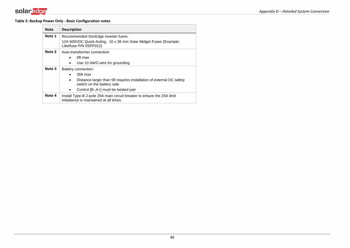
Appendix D – Detailed System Connection
49
Table 5: Backup Power Only - Basic Configuration notes
Note Description
Note 1 Recommended StorEdge inverter fuses:
12A 600VDC Quick-Acting, 10 x 38 mm Solar Midget Fuses (Example: Littelfuse P/N 0SPF012)
Note 2 Auto-transformer connection:
6ft max
Use 10 AWG wire for grounding
Note 3 Battery connection:
35ft max
Distance larger than 5ft requires installation of external DC safety switch on the battery side
Control [B-,A+] must be twisted pair
Note 4 Install Type-B 2-pole 25A main circuit breaker to ensure the 25A limit imbalance is maintained at all times.
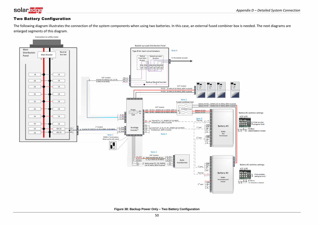
Appendix D – Detailed System Connection
50
Two Battery Configuration
The following diagram illustrates the connection of the system components when using two batteries. In this case, an external fused combiner box is needed. The next diagrams are
enlarged segments of this diagram.
Figure 38: Backup Power Only – Two Battery Configuration
20ACB
20ACB
20ACB
20ACB
Backed-up Loads Distribution Panel
BU_L1BU_L2
25ACB
25ACB
BU_N Backup Neutral bus-bar
Backup Panel Main
Breaker
Backed-up Loads Breakers To the backed-up loads
L1 L2
MainDistribution Panel
CB
CB
CB
CBCB
40A CB
CB 40A CB
Neutral bus-bar
L1_GridN_Grid
L2_Grid
Connection to utility meter
L1NL2
3
Main Breaker
3/4" Conduit
2
1" ConduitInverter AC Grid [L1, L2, N], 6 AWG (4-20 AWG)
PV DC+, 10 AWG (4-20 AWG), 600V insulated
PV DC- , 10 AWG (4-20 AWG), 600V insulated
Batt. HV DC+, 10AWG (10-12 AWG), 600V ins.Batt. HV DC-, 10AWG (10-12 AWG), 600V ins.
+-
V+V-
2
PWRV+G
5RTN
EnA+B-
ENPN
Thermal [V+, V-], 16AWG (12-16 AWG), Shielded pair, 600V insulated
Control [V+, G, En, A+, B-], 24AWG (16-24 AWG), Shielded pair, 600V insulated
+-
PWRRTNENPN
12A/600V fuses
Fused combiner box
1st port
2nd port
1st port
Thermal
Battery #1
RS485 Not
Terminated
Thermal
Battery HV DC+, 10AWG (10-12 AWG), 600V insulatedBattery HV DC- , 10AWG (10-12 AWG), 600V insulated
Battery HV DC+Battery HV DC-
PWR
ENPN
RTN
Battery #2
RS485Terminated and
biasedRTNENPN
2nd port
Battery #1 switches settings:
Battery #2 switches settings:
3/4" Conduit
StorEdge Inverter*
BATIN
Fuses
12A
Auto-transformer
3/4" ConduitL1_A.T.N_A.T.
L2_A.T.T1T2
Auto-transformer AC [L1, L2, N], 8 AWG (6-20 AWG)
3
2 Temp. sense [T1, T2], 24AWG (16-24 AWG), 600V insulated
L1_A.T.N_A.T.L2_A.T.
T1T2
L1_BUL2_BU
N_BU
Inverter AC Backup [L1, L2, N], 6 AWG (4-20 AWG)
CBCB
CBCB
CBCB
CBCB
CBCB
CBCB
NotesNote 1: StorEdge Inverter: SE7600A-USS0 supports double capacity SE7600A-USS2 supports double power and double capacity
- Replace the internal 12A fuses with 25A fuses for two batteriesRecommended Fuses in StorEdge Inverter: 12A 600VDC Quick-Acting, 10 x 38 mm Solar Midget Fuses (Example: littelfuse P/N 0SPF012) 25A 600VDC Quick-Acting, 10 x 38 mm Solar Midget Fuses (Example: littelfuse P/N 0SPF025)Note 2: External fused combiner box is needed to support two batteriesNote 3: Auto-transformer connection: 6ft max Vertical mounting only (conduit connection from the bottom) Use 10 AWG wire for groundingNote 4: Battery connection: 35ft max Distance larger than 5ft requires installation of external DC safety switch on the battery side Control [B-,A+] must be twisted pairNote 5: Use a twin-wire ferrules to daisy chain the thermal wiringNote 6: Install type B 2-pole 25A main circuit breaker to ensure the 25A phase limit imbalance is maintained at all times.
Note 1
Note 3
Note 4
Note 2
Note 5
RS485-1 TerminationsMove up the left switch
Note 6
33/4" Conduit
Type B for main circuit breakers
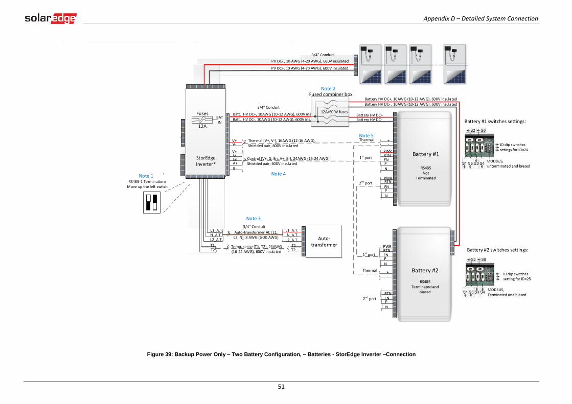
Appendix D – Detailed System Connection
51
Figure 39: Backup Power Only – Two Battery Configuration, – Batteries - StorEdge Inverter –Connection
20ACB
20ACB
20ACB
20ACB
Backed-up Loads Distribution Panel
BU_L1BU_L2
25ACB
25ACB
BU_N Backup Neutral bus-bar
Backup Panel Main
Breaker
Backed-up Loads Breakers To the backed-up loads
L1 L2
MainDistribution Panel
CB
CB
CB
CBCB
40A CB
CB 40A CB
Neutral bus-bar
L1_GridN_Grid
L2_Grid
Connection to utility meter
L1NL2
3
Main Breaker
3/4" Conduit
2
1" ConduitInverter AC Grid [L1, L2, N], 6 AWG (4-20 AWG)
PV DC+, 10 AWG (4-20 AWG), 600V insulated
PV DC- , 10 AWG (4-20 AWG), 600V insulated
Batt. HV DC+, 10AWG (10-12 AWG), 600V ins.Batt. HV DC-, 10AWG (10-12 AWG), 600V ins.
+-
V+V-
2
PWRV+G
5RTN
EnA+B-
ENPN
Thermal [V+, V-], 16AWG (12-16 AWG), Shielded pair, 600V insulated
Control [V+, G, En, A+, B-], 24AWG (16-24 AWG), Shielded pair, 600V insulated
+-
PWRRTNENPN
12A/600V fuses
Fused combiner box
1st port
2nd port
1st port
Thermal
Battery #1
RS485 Not
Terminated
Thermal
Battery HV DC+, 10AWG (10-12 AWG), 600V insulatedBattery HV DC- , 10AWG (10-12 AWG), 600V insulated
Battery HV DC+Battery HV DC-
PWR
ENPN
RTN
Battery #2
RS485Terminated and
biasedRTNENPN
2nd port
Battery #1 switches settings:
Battery #2 switches settings:
3/4" Conduit
StorEdge Inverter*
BATIN
Fuses
12A
Auto-transformer
3/4" ConduitL1_A.T.N_A.T.
L2_A.T.T1T2
Auto-transformer AC [L1, L2, N], 8 AWG (6-20 AWG)
3
2 Temp. sense [T1, T2], 24AWG (16-24 AWG), 600V insulated
L1_A.T.N_A.T.L2_A.T.
T1T2
L1_BUL2_BU
N_BU
Inverter AC Backup [L1, L2, N], 6 AWG (4-20 AWG)
CBCB
CBCB
CBCB
CBCB
CBCB
CBCB
NotesNote 1: StorEdge Inverter: SE7600A-USS0 supports double capacity SE7600A-USS2 supports double power and double capacity
- Replace the internal 12A fuses with 25A fuses for two batteriesRecommended Fuses in StorEdge Inverter: 12A 600VDC Quick-Acting, 10 x 38 mm Solar Midget Fuses (Example: littelfuse P/N 0SPF012) 25A 600VDC Quick-Acting, 10 x 38 mm Solar Midget Fuses (Example: littelfuse P/N 0SPF025)Note 2: External fused combiner box is needed to support two batteriesNote 3: Auto-transformer connection: 6ft max Vertical mounting only (conduit connection from the bottom) Use 10 AWG wire for groundingNote 4: Battery connection: 35ft max Distance larger than 5ft requires installation of external DC safety switch on the battery side Control [B-,A+] must be twisted pairNote 5: Use a twin-wire ferrules to daisy chain the thermal wiringNote 6: Install type B 2-pole 25A main circuit breaker to ensure the 25A phase limit imbalance is maintained at all times.
Note 1
Note 3
Note 4
Note 2
Note 5
RS485-1 TerminationsMove up the left switch
Note 6
33/4" Conduit
Type B for main circuit breakers

Appendix D – Detailed System Connection
52
Figure 40: Backup Power Only – Two Battery Configuration, Distribution Panel – Backed-up Loads Panel Connection
20ACB
20ACB
20ACB
20ACB
Backed-up Loads Distribution Panel
BU_L1BU_L2
25ACB
25ACB
BU_N Backup Neutral bus-bar
Backup Panel Main
Breaker
Backed-up Loads Breakers To the backed-up loads
L1 L2
MainDistribution Panel
CB
CB
CB
CBCB
40A CB
CB 40A CB
Neutral bus-bar
L1_GridN_Grid
L2_Grid
Connection to utility meter
L1NL2
3
Main Breaker
3/4" Conduit
2
1" ConduitInverter AC Grid [L1, L2, N], 6 AWG (4-20 AWG)
PV DC+, 10 AWG (4-20 AWG), 600V insulated
PV DC- , 10 AWG (4-20 AWG), 600V insulated
Batt. HV DC+, 10AWG (10-12 AWG), 600V ins.Batt. HV DC-, 10AWG (10-12 AWG), 600V ins.
+-
V+V-
2
PWRV+G
5RTN
EnA+B-
ENPN
Thermal [V+, V-], 16AWG (12-16 AWG), Shielded pair, 600V insulated
Control [V+, G, En, A+, B-], 24AWG (16-24 AWG), Shielded pair, 600V insulated
+-
PWRRTNENPN
12A/600V fuses
Fused combiner box
1st port
2nd port
1st port
Thermal
Battery #1
RS485 Not
Terminated
Thermal
Battery HV DC+, 10AWG (10-12 AWG), 600V insulatedBattery HV DC- , 10AWG (10-12 AWG), 600V insulated
Battery HV DC+Battery HV DC-
PWR
ENPN
RTN
Battery #2
RS485Terminated and
biasedRTNENPN
2nd port
Battery #1 switches settings:
Battery #2 switches settings:
3/4" Conduit
StorEdge Inverter*
BATIN
Fuses
12A
Auto-transformer
3/4" ConduitL1_A.T.N_A.T.
L2_A.T.T1T2
Auto-transformer AC [L1, L2, N], 8 AWG (6-20 AWG)
3
2 Temp. sense [T1, T2], 24AWG (16-24 AWG), 600V insulated
L1_A.T.N_A.T.L2_A.T.
T1T2
L1_BUL2_BU
N_BU
Inverter AC Backup [L1, L2, N], 6 AWG (4-20 AWG)
CBCB
CBCB
CBCB
CBCB
CBCB
CBCB
NotesNote 1: StorEdge Inverter: SE7600A-USS0 supports double capacity SE7600A-USS2 supports double power and double capacity
- Replace the internal 12A fuses with 25A fuses for two batteriesRecommended Fuses in StorEdge Inverter: 12A 600VDC Quick-Acting, 10 x 38 mm Solar Midget Fuses (Example: littelfuse P/N 0SPF012) 25A 600VDC Quick-Acting, 10 x 38 mm Solar Midget Fuses (Example: littelfuse P/N 0SPF025)Note 2: External fused combiner box is needed to support two batteriesNote 3: Auto-transformer connection: 6ft max Vertical mounting only (conduit connection from the bottom) Use 10 AWG wire for groundingNote 4: Battery connection: 35ft max Distance larger than 5ft requires installation of external DC safety switch on the battery side Control [B-,A+] must be twisted pairNote 5: Use a twin-wire ferrules to daisy chain the thermal wiringNote 6: Install type B 2-pole 25A main circuit breaker to ensure the 25A phase limit imbalance is maintained at all times.
Note 1
Note 3
Note 4
Note 2
Note 5
RS485-1 TerminationsMove up the left switch
Note 6
33/4" Conduit
Type B for main circuit breakers
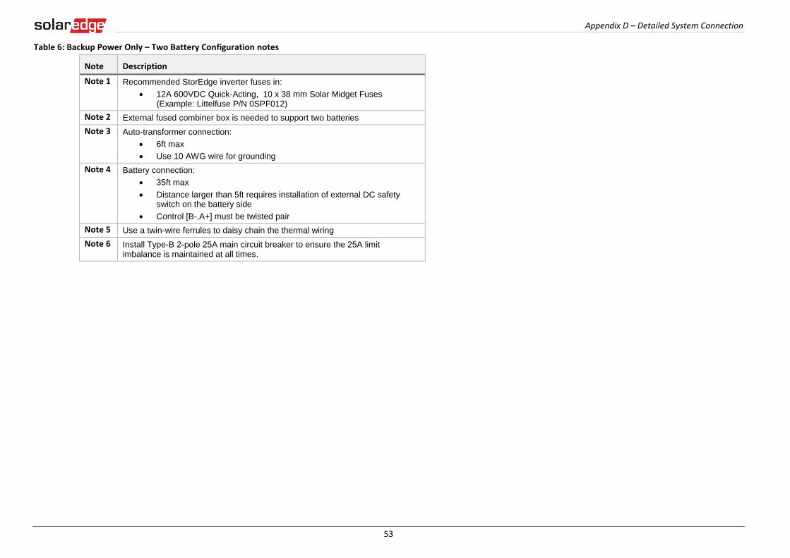
Appendix D – Detailed System Connection
53
Table 6: Backup Power Only – Two Battery Configuration notes
Note Description
Note 1 Recommended StorEdge inverter fuses in:
12A 600VDC Quick-Acting, 10 x 38 mm Solar Midget Fuses (Example: Littelfuse P/N 0SPF012)
Note 2 External fused combiner box is needed to support two batteries
Note 3 Auto-transformer connection:
6ft max
Use 10 AWG wire for grounding
Note 4 Battery connection:
35ft max
Distance larger than 5ft requires installation of external DC safety switch on the battery side
Control [B-,A+] must be twisted pair
Note 5 Use a twin-wire ferrules to daisy chain the thermal wiring
Note 6 Install Type-B 2-pole 25A main circuit breaker to ensure the 25A limit imbalance is maintained at all times.
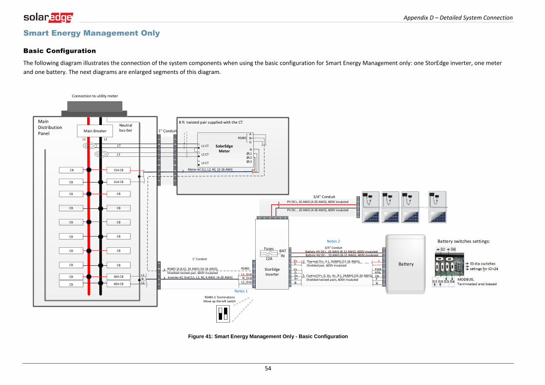
Appendix D – Detailed System Connection
54
Smart Energy Management Only
Basic Configuration
The following diagram illustrates the connection of the system components when using the basic configuration for Smart Energy Management only: one StorEdge inverter, one meter
and one battery. The next diagrams are enlarged segments of this diagram.
Figure 41: Smart Energy Management Only - Basic Configuration
Battery
L1 L2
MainDistribution Panel
CT
CT
CB
CB
15A CB
40A CB
CB 40A CB
Neutral bus-bar
L1_GridN_Grid
L2_Grid
Connection to utility meter
L1NL2
1" Conduit
3 Meter AC [L1, L2, N], 12-16 AWG
8 ft twisted pair supplied with the CT
RS485 [A,B,G], 24 AWG (16-24 AWG), Shielded twisted pair, 600V insulated
3 Inverter AC Grid [L1, L2, N], 6 AWG (4-20 AWG)
3
1" Conduit
Battery HV DC+, 10 AWG (8-12 AWG), 600V insulatedBattery HV DC- , 10 AWG (8-12 AWG), 600V insulated
+-
V+V-
2 Thermal [V+, V-], 16AWG (12-16 AWG), Shielded pair, 600V insulated
PWRV+G
5 Control [V+, G, En, A+, B-], 24AWG (16-24 AWG), Shielded twisted pairs, 600V insulated
RTNEnA+B-
ENPN
3/4" Conduit
RS485
SolarEdge Meter
A -B+G
NØL1ØL2ØL3
L1 CT
L2 CT
L3 CT
Main Breaker
3/4" ConduitPV DC+, 10 AWG (4-20 AWG), 600V insulated
PV DC- , 10 AWG (4-20 AWG), 600V insulated
22
StorEdge Inverter
BATIN
Fuses
12A
CBCB
CBCB
CBCB
CBCB
CBCB
CBCB
15A CBCB
NotesNote 1: Recommended Fuses in StorEdge Inverter: 12A 600VDC Quick-Acting, 10 x 38 mm Solar Midget Fuses
(Example: littelfuse P/N 0SPF012)
Note 2: Battery connection: 35ft max Distance larger than 5ft requires installation of external DC
safety switch on the battery side Control [B-,A+] must be twisted pair
Notes 1
Notes 2
RS485
RS485-1 TerminationsMove up the left switch
Battery switches settings:
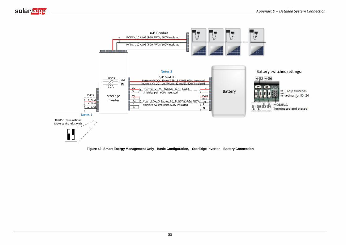
Appendix D – Detailed System Connection
55
Figure 42: Smart Energy Management Only - Basic Configuration, - StorEdge Inverter – Battery Connection
Battery
L1 L2
MainDistribution Panel
CT
CT
CB
CB
15A CB
40A CB
CB 40A CB
Neutral bus-bar
L1_GridN_Grid
L2_Grid
Connection to utility meter
L1NL2
1" Conduit
3 Meter AC [L1, L2, N], 12-16 AWG
8 ft twisted pair supplied with the CT
RS485 [A,B,G], 24 AWG (16-24 AWG), Shielded twisted pair, 600V insulated
3 Inverter AC Grid [L1, L2, N], 6 AWG (4-20 AWG)
3
1" Conduit
Battery HV DC+, 10 AWG (8-12 AWG), 600V insulatedBattery HV DC- , 10 AWG (8-12 AWG), 600V insulated
+-
V+V-
2 Thermal [V+, V-], 16AWG (12-16 AWG), Shielded pair, 600V insulated
PWRV+G
5 Control [V+, G, En, A+, B-], 24AWG (16-24 AWG), Shielded twisted pairs, 600V insulated
RTNEnA+B-
ENPN
3/4" Conduit
RS485
SolarEdge Meter
A -B+G
NØL1ØL2ØL3
L1 CT
L2 CT
L3 CT
Main Breaker
3/4" ConduitPV DC+, 10 AWG (4-20 AWG), 600V insulated
PV DC- , 10 AWG (4-20 AWG), 600V insulated
22
StorEdge Inverter
BATIN
Fuses
12A
CBCB
CBCB
CBCB
CBCB
CBCB
CBCB
15A CBCB
NotesNote 1: Recommended Fuses in StorEdge Inverter: 12A 600VDC Quick-Acting, 10 x 38 mm Solar Midget Fuses
(Example: littelfuse P/N 0SPF012)
Note 2: Battery connection: 35ft max Distance larger than 5ft requires installation of external DC
safety switch on the battery side Control [B-,A+] must be twisted pair
Notes 1
Notes 2
RS485
RS485-1 TerminationsMove up the left switch
Battery switches settings:

Appendix D – Detailed System Connection
56
Figure 43: Smart Energy Management Only - Basic Configuration, Main Distribution Panel - Electricity Meter Connection
Battery
L1 L2
MainDistribution Panel
CT
CT
CB
CB
15A CB
40A CB
CB 40A CB
Neutral bus-bar
L1_GridN_Grid
L2_Grid
Connection to utility meter
L1NL2
1" Conduit
3 Meter AC [L1, L2, N], 12-16 AWG
8 ft twisted pair supplied with the CT
RS485 [A,B,G], 24 AWG (16-24 AWG), Shielded twisted pair, 600V insulated
3 Inverter AC Grid [L1, L2, N], 6 AWG (4-20 AWG)
3
1" Conduit
Battery HV DC+, 10 AWG (8-12 AWG), 600V insulatedBattery HV DC- , 10 AWG (8-12 AWG), 600V insulated
+-
V+V-
2 Thermal [V+, V-], 16AWG (12-16 AWG), Shielded pair, 600V insulated
PWRV+G
5 Control [V+, G, En, A+, B-], 24AWG (16-24 AWG), Shielded twisted pairs, 600V insulated
RTNEnA+B-
ENPN
3/4" Conduit
RS485
SolarEdge Meter
A -B+G
NØL1ØL2ØL3
L1 CT
L2 CT
L3 CT
Main Breaker
3/4" ConduitPV DC+, 10 AWG (4-20 AWG), 600V insulated
PV DC- , 10 AWG (4-20 AWG), 600V insulated
22
StorEdge Inverter
BATIN
Fuses
12A
CBCB
CBCB
CBCB
CBCB
CBCB
CBCB
15A CBCB
NotesNote 1: Recommended Fuses in StorEdge Inverter: 12A 600VDC Quick-Acting, 10 x 38 mm Solar Midget Fuses
(Example: littelfuse P/N 0SPF012)
Note 2: Battery connection: 35ft max Distance larger than 5ft requires installation of external DC
safety switch on the battery side Control [B-,A+] must be twisted pair
Notes 1
Notes 2
RS485
RS485-1 TerminationsMove up the left switch
Battery switches settings:

Appendix D – Detailed System Connection
57
Table 7: Basic Configuration Smart Energy Management Notes
Note Description
Note 1 Recommended StorEdge inverter fuses:
12A 600VDC Quick-Acting, 10 x 38 mm Solar Midget Fuses (Example: Littelfuse P/N 0SPF012)
Note 2 Battery connection:
35ft max
Distance larger than 5ft requires installation of external DC safety switch on the battery side
Control [B-,A+] must be twisted pair
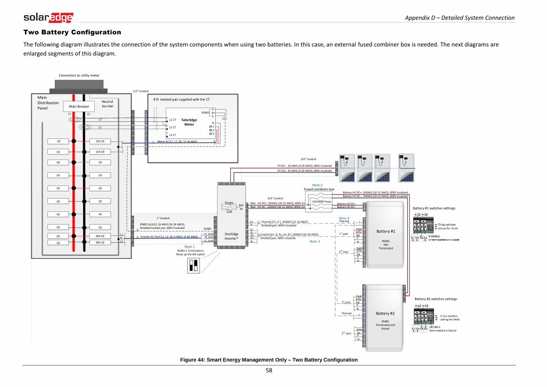
Appendix D – Detailed System Connection
58
Two Battery Configuration
The following diagram illustrates the connection of the system components when using two batteries. In this case, an external fused combiner box is needed. The next diagrams are
enlarged segments of this diagram.
Figure 44: Smart Energy Management Only – Two Battery Configuration
3 Meter AC [L1, L2, N], 12-16 AWG
8 ft twisted pair supplied with the CT
RS485
SolarEdge Meter
A -B+G
NØL1ØL2ØL3
L1 CT
L2 CT
L3 CT
L1 L2
MainDistribution Panel
CT
CT
RS485
CB
CB
15A CB
15A CBCB
40A CB
CB 40A CB
Neutral bus-bar
L1_GridN_Grid
L2_Grid
Connection to utility meter
L1NL2
3
3
1/2" Conduit
Main Breaker
3/4" Conduit
1" Conduit
RS485 [A,B,G], 24 AWG (16-24 AWG), Shielded twisted pair, 600V insulated
Inverter AC Grid [L1, L2, N], 6 AWG (4-20 AWG)
PV DC+, 10 AWG (4-20 AWG), 600V insulated
PV DC- , 10 AWG (4-20 AWG), 600V insulated
Batt. HV DC+, 10AWG (10-12 AWG), 600V ins.Batt. HV DC-, 10AWG (10-12 AWG), 600V ins.
+-
V+V-
2
PWRV+G
5RTN
EnA+B-
ENPN
Thermal [V+, V-], 16AWG (12-16 AWG), Shielded pair, 600V insulated
Control [V+, G, En, A+, B-], 24AWG (16-24 AWG), Shielded pair, 600V insulated
+-
PWRRTNENPN
12A/600V fuses
Fused combiner box
1st port
2nd port
1st port
Thermal
Battery #1
RS485 Not
Terminated
Thermal
Battery HV DC+, 10AWG (10-12 AWG), 600V insulatedBattery HV DC- , 10AWG (10-12 AWG), 600V insulated
Battery HV DC+Battery HV DC-
PWR
ENPN
RTN
Battery #2
RS485Terminated and
biasedRTNENPN
2nd port
Battery #1 switches settings:
Battery #2 switches settings:
3/4" Conduit
StorEdge Inverter*
BATIN
Fuses
12A
CBCB
CBCB
CBCB
CBCB
CBCB
CBCB
NotesNote 1: Recommended Fuses in StorEdge Inverter: 12A 600VDC Quick-Acting, 10 x 38 mm Solar Midget Fuses
(Example: littelfuse P/N 0SPF012)
Note 2: External fused combiner box is needed to support two batteries
Note 3: Battery connection: 35ft max Distance larger than 5ft requires installation of external DC safety
switch on the battery side Control [B-,A+] must be twisted pair
Note 4: Use a twin-wire ferrules to daisy chain the thermal wiring
Note 1
Note 3
Note 2
Note 4
RS485-1 TerminationsMove up the left switch
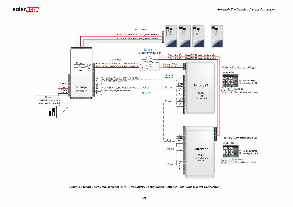
Appendix D – Detailed System Connection
59
Figure 45: Smart Energy Management Only – Two Battery Configuration, Batteries - StorEdge Inverter Connection
3 Meter AC [L1, L2, N], 12-16 AWG
8 ft twisted pair supplied with the CT
RS485
SolarEdge Meter
A -B+G
NØL1ØL2ØL3
L1 CT
L2 CT
L3 CT
L1 L2
MainDistribution Panel
CT
CT
RS485
CB
CB
15A CB
15A CBCB
40A CB
CB 40A CB
Neutral bus-bar
L1_GridN_Grid
L2_Grid
Connection to utility meter
L1NL2
3
3
1/2" Conduit
Main Breaker
3/4" Conduit
1" Conduit
RS485 [A,B,G], 24 AWG (16-24 AWG), Shielded twisted pair, 600V insulated
Inverter AC Grid [L1, L2, N], 6 AWG (4-20 AWG)
PV DC+, 10 AWG (4-20 AWG), 600V insulated
PV DC- , 10 AWG (4-20 AWG), 600V insulated
Batt. HV DC+, 10AWG (10-12 AWG), 600V ins.Batt. HV DC-, 10AWG (10-12 AWG), 600V ins.
+-
V+V-
2
PWRV+G
5RTN
EnA+B-
ENPN
Thermal [V+, V-], 16AWG (12-16 AWG), Shielded pair, 600V insulated
Control [V+, G, En, A+, B-], 24AWG (16-24 AWG), Shielded pair, 600V insulated
+-
PWRRTNENPN
12A/600V fuses
Fused combiner box
1st port
2nd port
1st port
Thermal
Battery #1
RS485 Not
Terminated
Thermal
Battery HV DC+, 10AWG (10-12 AWG), 600V insulatedBattery HV DC- , 10AWG (10-12 AWG), 600V insulated
Battery HV DC+Battery HV DC-
PWR
ENPN
RTN
Battery #2
RS485Terminated and
biasedRTNENPN
2nd port
Battery #1 switches settings:
Battery #2 switches settings:
3/4" Conduit
StorEdge Inverter*
BATIN
Fuses
12A
CBCB
CBCB
CBCB
CBCB
CBCB
CBCB
NotesNote 1: Recommended Fuses in StorEdge Inverter: 12A 600VDC Quick-Acting, 10 x 38 mm Solar Midget Fuses
(Example: littelfuse P/N 0SPF012)
Note 2: External fused combiner box is needed to support two batteries
Note 3: Battery connection: 35ft max Distance larger than 5ft requires installation of external DC safety
switch on the battery side Control [B-,A+] must be twisted pair
Note 4: Use a twin-wire ferrules to daisy chain the thermal wiring
Note 1
Note 3
Note 2
Note 4
RS485-1 TerminationsMove up the left switch
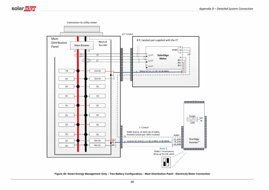
Appendix D – Detailed System Connection
60
Figure 46: Smart Energy Management Only – Two Battery Configuration, - Main Distribution Panel - Electricity Meter Connection
3 Meter AC [L1, L2, N], 12-16 AWG
8 ft twisted pair supplied with the CT
RS485
SolarEdge Meter
A -B+G
NØL1ØL2ØL3
L1 CT
L2 CT
L3 CT
L1 L2
MainDistribution Panel
CT
CT
RS485
CB
CB
15A CB
15A CBCB
40A CB
CB 40A CB
Neutral bus-bar
L1_GridN_Grid
L2_Grid
Connection to utility meter
L1NL2
3
3
1/2" Conduit
Main Breaker
3/4" Conduit
1" Conduit
RS485 [A,B,G], 24 AWG (16-24 AWG), Shielded twisted pair, 600V insulated
Inverter AC Grid [L1, L2, N], 6 AWG (4-20 AWG)
PV DC+, 10 AWG (4-20 AWG), 600V insulated
PV DC- , 10 AWG (4-20 AWG), 600V insulated
Batt. HV DC+, 10AWG (10-12 AWG), 600V ins.Batt. HV DC-, 10AWG (10-12 AWG), 600V ins.
+-
V+V-
2
PWRV+G
5RTN
EnA+B-
ENPN
Thermal [V+, V-], 16AWG (12-16 AWG), Shielded pair, 600V insulated
Control [V+, G, En, A+, B-], 24AWG (16-24 AWG), Shielded pair, 600V insulated
+-
PWRRTNENPN
12A/600V fuses
Fused combiner box
1st port
2nd port
1st port
Thermal
Battery #1
RS485 Not
Terminated
Thermal
Battery HV DC+, 10AWG (10-12 AWG), 600V insulatedBattery HV DC- , 10AWG (10-12 AWG), 600V insulated
Battery HV DC+Battery HV DC-
PWR
ENPN
RTN
Battery #2
RS485Terminated and
biasedRTNENPN
2nd port
Battery #1 switches settings:
Battery #2 switches settings:
3/4" Conduit
StorEdge Inverter*
BATIN
Fuses
12A
CBCB
CBCB
CBCB
CBCB
CBCB
CBCB
NotesNote 1: Recommended Fuses in StorEdge Inverter: 12A 600VDC Quick-Acting, 10 x 38 mm Solar Midget Fuses
(Example: littelfuse P/N 0SPF012)
Note 2: External fused combiner box is needed to support two batteries
Note 3: Battery connection: 35ft max Distance larger than 5ft requires installation of external DC safety
switch on the battery side Control [B-,A+] must be twisted pair
Note 4: Use a twin-wire ferrules to daisy chain the thermal wiring
Note 1
Note 3
Note 2
Note 4
RS485-1 TerminationsMove up the left switch
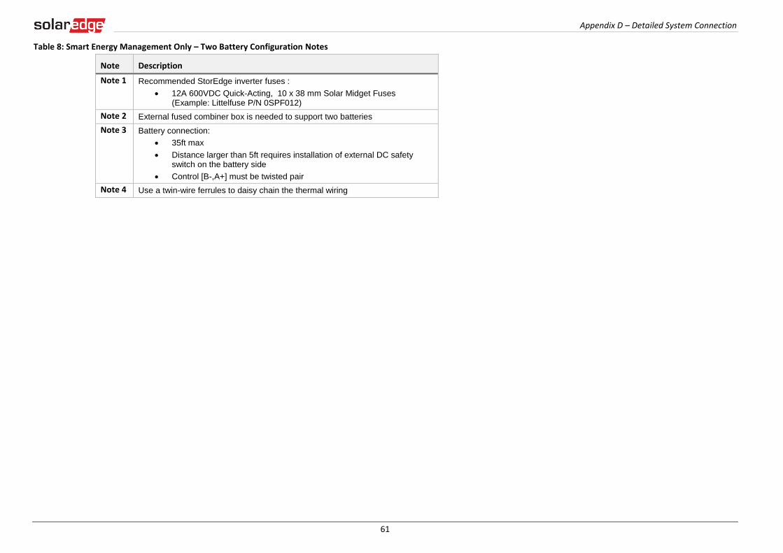
Appendix D – Detailed System Connection
61
Table 8: Smart Energy Management Only – Two Battery Configuration Notes
Note Description
Note 1 Recommended StorEdge inverter fuses :
12A 600VDC Quick-Acting, 10 x 38 mm Solar Midget Fuses (Example: Littelfuse P/N 0SPF012)
Note 2 External fused combiner box is needed to support two batteries
Note 3 Battery connection:
35ft max
Distance larger than 5ft requires installation of external DC safety switch on the battery side
Control [B-,A+] must be twisted pair
Note 4 Use a twin-wire ferrules to daisy chain the thermal wiring
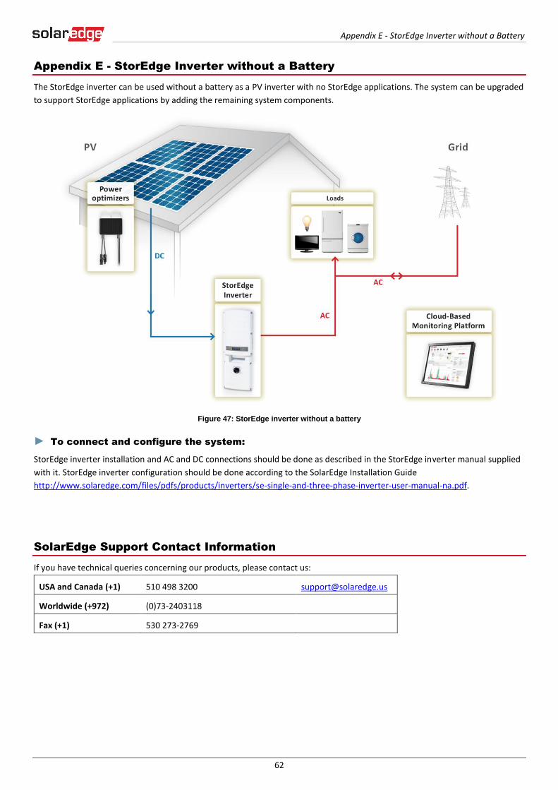
Appendix E - StorEdge Inverter without a Battery
62
Appendix E - StorEdge Inverter without a Battery
The StorEdge inverter can be used without a battery as a PV inverter with no StorEdge applications. The system can be upgraded
to support StorEdge applications by adding the remaining system components.
Figure 47: StorEdge inverter without a battery
► To connect and configure the system:
StorEdge inverter installation and AC and DC connections should be done as described in the StorEdge inverter manual supplied
with it. StorEdge inverter configuration should be done according to the SolarEdge Installation Guide
http://www.solaredge.com/files/pdfs/products/inverters/se-single-and-three-phase-inverter-user-manual-na.pdf.
SolarEdge Support Contact Information
If you have technical queries concerning our products, please contact us:
USA and Canada (+1) 510 498 3200 [email protected]
Worldwide (+972) (0)73-2403118
Fax (+1) 530 273-2769