RDC eyes reactivation of Investment Promotion Group /p.5 RDC ...
Upload
truonghanhCategory
view
220download
0
StorageTek™Shared Virtual Array (SVA)
V2X/V2X2 Reference
Part Number : 96219Revision N


StorageTek™ Shared Virtual Array (SVA)V2X/V2X2Reference

Copyright 2006 Sun Microsystems, Inc., 4150 Network Circle, Santa Clara, California 95054, U.S.A. All rights reserved.
Sun Microsystems, Inc. has intellectual property rights relating to technology that is described in this document. In particular, and without limitation, these intellectual property rights might include one or more of the U.S. patents listed at http://www.sun.com/patents and one or more additional patents or pending patent applications in the U.S. and in other countries.
This document and the product to which it pertains are distributed under licenses restricting their use, copying, distribution, and decompilation. No part of the product or of this document might be reproduced in any form by any means without prior written authorization of Sun and its licensors, if any.
Third-party software, including font technology, is copyrighted and licensed from Sun suppliers.
Parts of the product might be derived from Berkeley BSD systems, licensed from the University of California. UNIX is a registered trademark in the U.S. and in other countries, exclusively licensed through X/Open Company, Ltd.
Sun, Sun Microsystems, the Sun logo, Java, AnswerBook2, docs.sun.com, StorageTek, StorageTek logo, VolSafe, and Solaris are trademarks or registered trademarks of Sun Microsystems, Inc. in the U.S. and in other countries.
All SPARC trademarks are used under license and are trademarks or registered trademarks of SPARC International, Inc. in the U.S. and in other countries. Products bearing SPARC trademarks are based upon an architecture developed by Sun Microsystems, Inc.
The OPEN LOOK and Sun™ Graphical User Interface was developed by Sun Microsystems, Inc. for its users and licensees. Sun acknowledges the pioneering efforts of Xerox in researching and developing the concept of visual or graphical user interfaces for the computer industry. Sun holds a non-exclusive license from Xerox to the Xerox Graphical User Interface, which license also covers Sun’s licensees who implement OPEN LOOK GUIs and otherwise comply with Sun’s written license agreements.
U.S. Government Rights—Commercial use. Government users are subject to the Sun Microsystems, Inc. standard license agreement and applicable provisions of the FAR and its supplements.
DOCUMENTATION IS PROVIDED "AS IS" AND ALL EXPRESS OR IMPLIED CONDITIONS, REPRESENTATIONS AND WARRANTIES, INCLUDING ANY IMPLIED WARRANTY OF MERCHANTABILITY, FITNESS FOR A PARTICULAR PURPOSE OR NON-INFRINGEMENT, ARE DISCLAIMED, EXCEPT TO THE EXTENT THAT SUCH DISCLAIMERS ARE HELD TO BE LEGALLY INVALID.
Copyright 2006 Sun Microsystems, Inc., 4150 Network Circle, Santa Clara, California 95054, Etats-Unis. Tous droits réservés.
Sun Microsystems, Inc. a les droits de propriété intellectuels relatants à la technologie qui est décrit dans ce document. En particulier, et sans la limitation, ces droits de propriété intellectuels peuvent inclure un ou plus des brevets américains énumérés à http://www.sun.com/patents et un ou les brevets plus supplémentaires ou les applications de brevet en attente dans les Etats-Unis et dans les autres pays.
Ce produit ou document est protégé par un copyright et distribué avec des licences qui en restreignent l’utilisation, la copie, la distribution, et la décompilation. Aucune partie de ce produit ou document ne peut être reproduite sous aucune forme, par quelque moyen que ce soit, sans l’autorisation préalable et écrite de Sun et de ses bailleurs de licence, s’il y en a.
Le logiciel détenu par des tiers, et qui comprend la technologie relative aux polices de caractères, est protégé par un copyright et licencié par des fournisseurs de Sun.
Des parties de ce produit pourront être dérivées des systèmes Berkeley BSD licenciés par l’Université de Californie. UNIX est une marque déposée aux Etats-Unis et dans d’autres pays et licenciée exclusivement par X/Open Company, Ltd.
Sun, Sun Microsystems, le logo Sun, Java, AnswerBook2, docs.sun.com StorageTek, StorageTek logo, VolSafe, et Solaris sont des marques de fabrique ou des marques déposées de Sun Microsystems, Inc. aux Etats-Unis et dans d’autres pays.
Toutes les marques SPARC sont utilisées sous licence et sont des marques de fabrique ou des marques déposées de SPARC International, Inc. aux Etats-Unis et dans d’autres pays. Les produits portant les marques SPARC sont basés sur une architecture développée par Sun Microsystems, Inc.
L’interface d’utilisation graphique OPEN LOOK et Sun™ a été développée par Sun Microsystems, Inc. pour ses utilisateurs et licenciés. Sun reconnaît les efforts de pionniers de Xerox pour la recherche et le développement du concept des interfaces d’utilisation visuelle ou graphique pour l’industrie de l’informatique. Sun détient une license non exclusive de Xerox sur l’interface d’utilisation graphique Xerox, cette licence couvrant également les licenciées de Sun qui mettent en place l’interface d ’utilisation graphique OPEN LOOK et qui en outre se conforment aux licences écrites de Sun.
LA DOCUMENTATION EST FOURNIE "EN L’ÉTAT" ET TOUTES AUTRES CONDITIONS, DECLARATIONS ET GARANTIES EXPRESSES OU TACITES SONT FORMELLEMENT EXCLUES, DANS LA MESURE AUTORISEE PAR LA LOI APPLICABLE, Y COMPRIS NOTAMMENT TOUTE GARANTIE IMPLICITE RELATIVE A LA QUALITE MARCHANDE, A L’APTITUDE A UNE UTILISATION PARTICULIERE OU A L’ABSENCE DE CONTREFAÇON.
We welcome your feedback. Please contact the Sun Learning Solutions Feedback System at:[email protected]
Global Learning Solutions Sun Microsystems, Inc. One StorageTek Drive Louisville, CO 80028-3256 USA
Please include the publication name, part number, and edition number in your correspondence if they are available. This expedites our response.
PleaseRecycle

96219 Revision N 3
Table of ContentsList of Tables 1Preface 5
Notices 5United States FCC Compliance Statement 5Agency Compliance Statement 5CISPR 22 and EN55022 Warning 5Japanese Compliance Statement 6Taiwan Warning Label Statement 6Internal Code License Statement 6Alert Messages 10Mensajes de alerta 10
Related Documents 11Viewing and Printing Web-Based Electronic Documents 13History of Changes 13
1 Addressing, Commands, and Status 15Attachments 15Channel Addressing 15
Subsystem Identifier 15Functional Device Identifier 15Interface Device Identifier 16Channel Address Configuration 16
I/O Channel Interface 16Processing Commands 18
Asynchronous Operations 18Channel Path Group ID 19Channel Exception Conditions 19
System Reset Processing 19Selective Reset Processing 20Interface Disconnect Processing 20
Owed Device End 21Channel Error Management 21
Channel Command Retry 21Disconnect-in 21Disconnected Device Status Time-out 22
Path Control 22Dynamic Path Reconnect 22Single Path Mode 22Multipath Mode 23
Path Control Commands 23Suspend Multipath Reconnection 23Set Path Group ID 23Sense Path Group ID 24Device Reserve 24Device Release 25Unconditional Reserve 26
4 Revision N 96219
Reset Allegiance 262 Command Description 29
CCW Flags 30Chain Data (CD) 30
Chain Command (CC) 30Suppress Length Indicator (SLI) 30Skip (SKIP) 30Program-Controlled Interruption (PCI) 30Indirect Data Address (IDA) 30Suspend (S) 31Flag bit 39 or 15 31
Exception Conditions 31Multitrack Operations 31
In a Locate Record or Locate Record Extended Domain 31Outside the Locate Record or Locate Record Extended Domain 32
Command Suspension or Resumption 32Command Summary 33Status Presented To Commands 36Addressing and Control Commands 39
Basic Address And Control Commands 39Read Device Characteristics 40
Ending Status 42RDC Bytes 0 and 1 42RDC Byte 2 42RDC Bytes 3 and 4 42RDC Byte 5 42RDC Bytes 6 through 9 42RDC Byte 10 43RDC Byte 11 44RDC Bytes 12 and 13 44RDC Bytes 14 and 15 44RDC Byte 16 44RDC Bytes 17 through 19 44RDC Bytes 20 and 21 44RDC Byte 22 44RDC Bytes 23 through 27 46RDC Bytes 28 and 29 46RDC Bytes 30 and 31 46RDC Bytes 32 and 33 46RDC Bytes 34 and 35 46RDC Bytes 36 and 37 46RDC Bytes 38 and 39 46RDC Byte 40 46RDC Byte 41 46RDC Byte 42 46RDC Byte 43 46RDC Bytes 44 and 45 47RDC Byte 46 47

96219 Revision N 5
RDC Byte 47 47RDC Byte 48 47RDC Bytes 49 and 50 47RDC Bytes 51-53 48RDC Byte 54 48RDC Byte 55 48RDC Byte 56 48RDC Byte 57 48RDC Bytes 58-63 48
Read Commands 48Search Commands 49Write Commands 49Sense Commands 50
Sense 50Sense ID 50
Miscellaneous Commands 53Test I/O 53No-Operation 53Read and Reset Buffered Log 54Diagnostic Control 54
Byte 0 - Subcommand Byte 57Locate Data Checks - ‘01’ Subcommand 57Inhibit Write - ‘02’ Subcommand 57Set Guaranteed Path - ‘04’ Subcommand 58Select Subsystem Data - ‘06’ Subcommand 58Select Trace - ‘07’ Subcommand 58Enable Write - ‘08’ Subcommand 593380 Track Compatibility Mode Control - ‘09’ Subcommand 59Prepare Remote Support Access Code - ‘0A’ Subcommand 59Diagnostic Initialize Subsystem - ‘0B’ Subcommand 60Unfence - ‘0C’ Subcommand 61Start Application - ‘0D’ Subcommand 61Access Device in Unknown Condition - ‘0F’ Subcommand 61Media Maintenance Reserve - ‘10’ Subcommand 61Media Maintenance Release - ‘11’ Subcommand 62Media Maintenance Query - ‘12’ Subcommand 62Remote Service Access - ‘13’ Subcommand 62
Diagnostic Sense/Read 62Diagnostic Write 63Read Configuration Data 64
Bytes 0 through 31 - NED 1 65Bytes 32 through 63 - NED 2 66Bytes 64 through 95 - NED 3 67Bytes 96 through 223 - NED 4 69Bytes 224 through 255 - NEQ 70Functional Device Model (RCD Bytes 10-12) 72Subsystem Physical Cache Size (RCD Byte 75) 74
Path Control Commands 74

6 Revision N 96219
Device Reserve 74Device Release 75Unconditional Reserve 76Reset Allegiance 78Set Path Group ID 81
Byte 0 - Function Control byte 82Byte 0, Bit 0 - Single Path Mode 82Byte 0, Bit 1 - Multipath Mode 83Byte 0, Bits 1 and 2 83Byte 0, Bits 3 through 7 83
Sense Path Group ID 83Byte 0 - Path State Byte 84Byte 0, Bits 0 and 1 84Byte 0, Bits 2 and 3 85Byte 0, Bit 4 85
Suspend Multipath Reconnection 85Subsystem Commands 86
Set Subsystem Mode 86Ending Status 88SSM Byte 0 - Cache Control, CFW Control, and Message Required Bit 89SSM Byte 0, Bits 0 through 2 90SSM Byte 0, Bits 3 through 5 93SSM Byte 1 - Nonvolatile Storage Control 94SSM Byte 1, Bits 0 through 2 95
Perform Subsystem Function 97Commit X‘10’ 99Discard X‘11’ 102Prepare for Read Subsystem Data X‘18’ 103Destage Modified Tracks X‘19’ 106Set Special Intercept Conditions X’1B’ 107SVASet Interface Identifier X‘B0’ 108
Sense Subsystem Status 110Ending Status 112SNSS Byte 4 - Overall Caching Status 112SNSS Byte 5 - Overall Nonvolatile Storage (NVS) Status 113SNSS Bytes 26 and 27 - Addressed Device Status (Part 1) 113SNSS Byte 36 - Addressed Device Status (Part 2) 114
Read Subsystem Data 115Ending Status 116Storage Path Status 116Subsystem Statistics 117Cache Fast Write Identifier 121Message Buffer 121Pinned-Track Data 123Node Descriptor 123Node Qualifiers 125
Read Message ID 127
96219 Revision N 7
3 ECKD 32-Byte Sense Data 129Sense Byte Structure and Description 129ECKD 32-Byte Sense Data Summary 130ECKD 32-Byte Sense Data Definitions 132
Sense Bytes 0 and 1 - Unit Check Description 132Byte 0, Bit 0 132Byte 0, Bit 1 - Intervention Required 132Byte 0, Bit 2 132Byte 0, Bit 3 - Equipment Check 133Byte 0, Bit 4 - Data Check 133Byte 0, Bit 5 133Byte 0, Bit 6 133Byte 0, Bit 7 133Byte 1, Bit 0 - Permanent Error 134Byte 1, Bit 1 134Byte 1, Bit 2 134Byte 1, Bit 3 - Message to Operator 134Byte 1, Bit 4 134Byte 1, Bits 5 through 7 134
Sense Byte 2 - Storage Control Type 134Sense Byte 3 - Remaining Intent Count 134Sense Byte 4 - Device Address 135Sense Byte 5 - Device Type Code 135Sense Byte 6 - Content and Format 136
Byte 6, Bit 0 - Reporting Unit 136Byte 6, Bit 1 - Device Address is Valid 136Byte 6, Bit 3 136Byte 6, Bits 4 through 7 136
Sense Byte 7 - Sector Number or Data Overrun Flag 137Sense Bytes 8 and 9 - Record ID or Number of Motion Seeks 137Sense Bytes 10 through 12 - Record ID or Time-Of-Day 137Sense Bytes 13 and 14 - Time-of-Day 138Sense Bytes 15 and 16 - Manufacturer, Product, and Plant ID 138
Sense Byte 15 138Sense Byte 16 138
Sense Bytes 17 through 19 - Frame Serial Number 139Sense Bytes 20 and 21 - SSID 139
Sense Byte 20 139Sense Byte 21 139
Sense Bytes 22 and 23 - Fault Symptom Code (FSC) 139Sense Byte 24 - Logging and Message Control 140
Byte 24, Bits 0 through 2 140Byte 24, Bit 3 140Byte 24, Bit 4 and 5 - Logging Action 140Byte 24, Bits 6 and 7 - Operator Message Control 141
Sense Byte 25 - Program Action Code 141Single Program Action Codes 142Compound Program Action Codes 143
8 Revision N 96219
Sense Bytes 26 and 27 - Configuration Data 145Sense Byte 26 145Sense Byte 27 145
Sense Byte 28 - Message Code or Bytes Read and Searched 146Sense Byte 29 - 31 - Track Address or Bytes Read and Searched 146
Byte 29 - High Cylinder Address 147Byte 30 - Low Cylinder Address 147Byte 31 - Head Address 147
ECKD 32-Byte Sense Exception Classes 148Exception Class 3 - Storage Path Checks 148Exception Class 4 - Data Checks 148Exception Class 6 - Subsystem Information 149Exception Class 7 - Support Facility Errors 149Exception Class B - Controller-to-Head-of-String Interface Errors 149Exception Class C - Head-of-String Errors 149Exception Class D - Head-of-String to Device Interface Errors 149Exception Class E - Device Errors 150Exception Class F - Cache and NVS Checks 150
4 24-Byte Compatibility Sense Data 151Sense Byte Structure and Meaning 15124-Byte Compatibility Sense Data Summary 15224-Byte Compatibility Sense Data Definitions 153
Sense Bytes 0, 1, and 2 - Unit Check Description 153Byte 0, Bit 0 - Command Reject 153Byte 0, Bit 1 - Intervention Required 154Byte 0, Bit 2 - Bus Out Parity Check 155Byte 0, Bit 3 - Equipment Check 155Byte 0, Bit 4 - Data Check 155Byte 0, Bit 5 - Overrun 156Byte 0, Bits 6 and 7 156Byte 1, Bit 0 - Permanent Error 156Byte 1, Bit 1 - Invalid Track Format 156Byte 1, Bit 2 - End of Cylinder 157Byte 1, Bit 3 - Message to Operator 157Byte 1, Bit 4 - No Record Found 157Byte 1, Bit 5 - File Protected 157Byte 1, Bits 6 and 7 157Byte 2, Bit 0 157Byte 2, Bit 1 - Correctable 158Byte 2, Bit 2 158Byte 2, Bit 3 - Environmental Data Present 158Byte 2, Bit 4 158Byte 2, Bit 5 158Byte 2, Bits 6 and 7 158
Sense Byte 3 - Residual Count, ECAM Message ID, or Controller ID 158Sense Bytes 4, 5, and 6 158
Sense Byte 4 - Device Address 159Sense Byte 5 - Low-Order Cylinder Address 159
96219 Revision N 9
Sense Byte 6 - Head and High-Order Cylinder Address 160Sense Byte 7 - Format and Message 161Sense Byte 8 - Reason Code, Record ID, or Bytes Read/Searched 161Sense Bytes 9 and 10 162Sense Byte 11 162Sense Byte 12 163Sense Byte 13 164Sense Byte 14 164Sense Bytes 15 and 16 - Manufacturer, Product, and Plant ID 165
Sense Byte 15 165Sense Byte 16 165
Sense Bytes 17 through 19 - Frame Serial Number 165Sense Bytes 20 and 21 - SSID 165
Sense Byte 20 166Sense Byte 21 166
Sense Bytes 22 and 23 - Fault Symptom Code (FSC) 166Sense Byte 24 166Sense Byte 25 - Program Action Code 166Sense Bytes 26 and 27 - Configuration Data 167
Sense Byte 26 167Sense Byte 27 167
Sense Byte 28 168Sense Bytes 29, 30, and 31 168
Byte 29 - High Cylinder Address 169Byte 30 - Low Cylinder Address 169Byte 31 - Head Address 169
24-Byte Compatibility Sense Formats Summary 17024-Byte Compatibility Sense Formats and Messages 170
Format 0 Messages - Program or System Checks 170Format 1 Messages - Device Equipment Checks 172Format 2 Messages - Controller Equipment Checks 173Format 3 Messages - Controller Control Checks 173Format 4 Messages - Data Checks 174Format 5 Messages - Data Checks in PCI Mode 174Format 6 Messages - Usage Statistics and Time-of-Day 174Format F Messages - Cache and NVS Checks 176
Reason Codes 178Reason Codes for Format 0 Message 178Reason Codes for Format F, Message 2 182Reason Codes for Format F, Message 6 182Reason Codes for Format F, Message 9 183Reason Codes for State-Change Pending Sense Data 183
Sense Bytes 13 and 14 - Subsystem State-Change-Pending Reason Codes (FSC FFF0) 184Sense Bytes 8-10 - Functional Device State-Change-Pending Reason Codes (FSC FFF1) 184Sense Bytes 13 and 14 - Functional Device State-Change-Pending Reason Codes (when bytes 8-10 contain 000050 (FSC FFF1)) 186

10 Revision N 96219
Sense Bytes 13 and 14 - Functional Device State-Change-Pending Reason Code (when Bytes 8-10 contain 000048 (FSCFFF1)) 186
5 SIM Sense Data 189SIM Sense Byte 1 - Unit Check Description 189SIM Sense Byte 2 - Storage Control Type or Environmental Data Present 190SIM Sense Byte 6 - Content and Format 190SIM Sense Byte 7 - SIM Sense Record ID or Not Used 190SIM Sense Byte 8 - Exception or Service Message Codes 190SIM Sense Bytes 9 and 10 - Message Modifiers 195SIM Sense Byte 11 - 14 - ECAM SIMs 196SIM Sense Byte 11 - Same as Previous Error or Feature Code 197SIM Sense Byte 12 - Available Cache 197SIM Sense Byte 13 - Unit Address 197SIM Sense Byte 14 - Machine-Initiated Maintenance Information 198SIM Sense Byte 28 - SIM Code 199SIM Sense Bytes 29-31 - SIM Modifiers 199
6 Host Error Recovery Procedures 201Error Recovery Actions Supported for 24-Byte Compatibility Sense 201
Error Recovery Action 1 201Error Recovery Action 2 202Error Recovery Action 3 202Error Recovery Action 4 202Error Recovery Action 5 203Error Recovery Action 6 203Error Recovery Action 7 204Error Recovery Action 8 205Error Recovery Action 9 210Error Recovery Action 10 210Error Recovery Action 11 210
Error Recovery Actions Supported for ECKD 32-Byte Sense 211Action 00 211Action 01 211Action 02 211Action 10 212Action 1C 212
A Channel Commands and Parameter Information 213Write Special Home Address Command (X09) 213Read Special Home Address Command (X0A) 213Space Count Command (X0F) 214Write Record Zero Command (X15) 214Read Record Zero Command (X16) 214Write Home Address Command (X19) 215Read Home Address Command (X1A) 215Perform Subsystem Function Command With: 215
Commit Order (X27/X10) 215Discard Order (X27/X11) 215Establish Duplex Pair Order (X27/X12) 215

96219 Revision N 11
Terminate Duplex Pair Order (X27/X13) 215Terminate Suspend Pair Order (X27/X14) 215Direct I/O Order (X27/X16) 215Prepare for Read Subsystem Data Order & Read Storage Path Status Suborder (X27/X18/X00) 216Prepare for Read Subsystem Data Order & Read Statistics Suborder (X27 / X18 / X01) 216Prepare for Read Subsystem Data Order & Read Current Cache Fast Write ID (X27 / X18 / X01) 216Prepare for Read Subsystem Data Order & Read Message (X27 /X18 / X03) 216Prepare for Read Subsystem Data Order & Read Un-synchronized Cylinders (X27 / X18 / X04) 216Prepare for Read Subsystem Data Order and a Read Pinned Tracks (X27 / X18 / X05) 217Set Special Intercept Order (X27 / X1B) 217
Modified Tracks Order (X27 / X19) 217Search Home Address (X39) 217Read Subsystem Data Order (X3E) 217Locate Record (X47) 217Read Message ID (X4E) 218Sense Subsystem Status (X54) 218Read Device Characteristics (X64) 218Diagnostic Write (X73) 218Set Subsystem Mode (X87/X0000) 218Set subsystem Mode With: 219
Cache Control - Activate Device (X87/X2000) 219Cache Control - Deactivate Device (X87/X4000) 219Cache Control - Activate Subsystem (X87/X6000) 219Cache Control - Deactivate Subsystem (X87/XA000) 219Cache Control - Force Deactivate Subsystem (X87/X9000) 219Cache Fast Write Control - Activate CFW for the Subsystem (X87/X0C00) 220Cache Fast Write Control - Deactivate CFW for the Subsystem (X87/X1000) 220Asynchronous Message Required (X87/X0100) 220DASD Fast Write Control - Activate (X87/X0020) 220DASD Fast Write Control - Deactivate (X87/X0040) 220DASD Fast Write Control - Force Deactivate (X87/X0060) 220Nonvolatile Storage Control - Activate (X87/X0080) 220Nonvolatile Storage Control - Deactivate (X87/X00A0) 220
Diagnostic Sense/Read Preceded by a Diagnostic Control 221Locate Data Checks (XC4/X01) 221Select Subsystem Data (XC4/X06) 221Read Remote Support Access Code (XC4/X0A) 221
Start Application (XC4/X07) 221Diagnostic Control With: 221
Locate Data Checks (XF3/X01) 221Inhibit Write (XF3/X02) 221Set Guaranteed Path (XF3/X04) 222Select Subsystem Data (XF3/X06) 222
12 Revision N 96219
Select Trace (XF3/X07) 222Enable Write (XF3/X07) 2223380 Track Compatibility Mode (XF3/X09) 222Read Remote Support Access Code (XF3/X0A) 222Diagnostic Initialize Subsystem (XF3/X0B) 222Un-fence Storage Path (XF3/X0C) 222Start Application (XF3/X0D) 223Access Device in Unknown Condition (XF3/X0F) 223Media Maintenance Reserve (XF3/X10) 223Media Maintenance Release (XF3/X11) 223Media Maintenance Query (XF3/X12) 223Remote Service Access (XF3/X13) 223
Read Configuration Data (XFA) 223No-Operation Commands 223Unit Check, Invalid Command 223Unit Check, Invalid Parameter 224Subcommands 224Device Busy at End of Chain 224Orientation Error Reporting for Locate Record 224Incomplete Domain Error Reporting 224
B Non-SIM Sense Data for Back-End Errors 225C Standard Device Characteristics 227D Read Subsystem Data (RSSD) Differences 233
Differences Between IBM RSSD and the SVA RSSD 233Hits and Misses 233Pre-staging 234Search counts incremented at Locate Record 234Destages 234NVS constraint 234Force Bypass Cache 234Non-primary cylinders 234C0H0 235
Major Differences between the SVA RSSD and ECAM 235Write hits and misses 235Cache Fast Write 235Write Operations 235Bypass cache and ICL operations 235Effect of cache status 236Pre-staging 237Search or Read Normal I/O Requests 237Search or Read Normal I/O Request Hits 239Write Normal I/O Requests 240DASD Fast Write I/O Request Hits 242Search or Read Sequential I/O Requests 243Search or Read Sequential I/O Request Hits 244Write Sequential I/O Requests 246DASD Fast Write Sequential I/O Request Hits 247
96219 Revision N 13
Search or Read Cache Fast Write I/O Requests 249Search or Read Cache Fast Write I/O Request Hits 250Cache Fast Write I/O Requests 252Cache Fast Write I/O Request Hits 254Inhibit Cache Loading I/O Requests 256Bypass Cache I/O Requests 257Sequential DASD-to-Cache Transfer Operations 258DASD-to-Cache Transfer Operations 260Cache-to-DASD Transfer Operations 262DASD Fast Write Normal Write Operation Counts 263DASD Fast Write Sequential Write Operation Counts 265

14 Revision N 96219
96219 Revision N 1
List of Tables
Table 1 Channel Addressing (Maximum 4096 Configurable) 17Table 2 Set Path Group ID Control Byte 0 24Table 3 CCW Formats 29Table 4 Summary of the SVA Channel Commands 34Table 5 Effect of Subsystem and Device Status on the Status Presented to Commands 37Table 7 Read Device Characteristics Format 40Table 6 Addressing Commands, Mnemonics and Hex Codes 40Table 8 RDC Byte 2 42Table 9 RDC Byte 6 42Table 10 RDC Byte 7 43Table 11 RDC Byte 8 43Table 12 RDC Byte 9 43Table 13 Read Commands, Mnemonics, and Hex Codes. 48Table 14 Search Commands, Mnemonics, and Hex Codes 49Table 15 Write Commands, Mnemonic, and Hex Codes 49Table 16 Sense Command, Mnemonic, and Hex Code 50Table 17 Sense ID Command, Mnemonic, and Hex Code 50Table 18 Sense ID Status Bytes 51Table 19 Test I/O Command, Mnemonic, and Hex Code 53Table 20 No-Operation Command, Mnemonic, and Hex Code 53Table 21 Read and Reset Buffered Log Command, Mnemonic, and Hex Code 54Table 22 Diagnostic Control Parameters 55Table 23 ‘02’ - Inhibit Write Subcommand Modifiers 58Table 24 ‘04’ - Set Guaranteed Path Subcommand Modifiers 58Table 25 ‘0A’ - Prepare Remote Access Code Subcommand 59Table 26 ‘0B’ - Diagnostic Initialize Subsystem Subcommand 60Table 27 Diagnostic Sense/Read Command 62Table 28 Byte 0 - Diagnostic Control Command Subcommands 63Table 29 Diagnostic Write Command, Mnemonic, and Hex Code 63Table 30 Read Configuration Data Command, Mnemonic, and Hex Code 64Table 31 Read Configuration Data Bytes 0 through 31 65Table 32 Read Configuration Data Bytes 32 through 63 66Table 33 Read Configuration Data Bytes 64 through 95 67Table 34 Read Configuration Data Bytes 96 through 223 69Table 35 Read Configuration Data Bytes 224 through 255 70Table 36 Subsystem Physical Cache Size 74Table 37 Path Control Command, Mnemonic, and Hex Code 74Table 38 Read Configuration Data Command, Mnemonic, and Hex Code 75Table 39 Unconditional Reserve Command, Mnemonic, and Hex Code 76Table 40 Reset Allegiance Command, Mnemonic, and Hex Code 78Table 41 Data Returned for Reset Allegiance 79Table 42 Set Path Group ID Command, Mnemonic, and Hex Code 81Table 43 Byte 0 - Function Control Byte 82

96219 Revision N 2
Table 44 Set Path Group ID Command, Mnemonic, and Hex Code 83Table 45 Byte 0 - Path State Byte 84Table 46 Suspend Multipath Reconnection Command, Mnemonic, and Hex Code 85Table 47 Set Subsystem Mode Command, Mnemonic, and Hex Code 86Table 48 Byte 0 - Cache Control and Message Required Bit 89Table 49 Byte 1 - Nonvolatile Storage Control Byte 94Table 50 Perform Subsystem Function Command, Mnemonic, and Hex Code 97Table 51 Perform Subsystem Function Orders and Flags 98Table 52 Byte 0 - Parameter Bytes for Commit X‘10’ 100Table 53 Parameter Bytes for Discard X‘11’ 102Table 54 Parameter Bytes for Prepare for Read Subsystem Data X‘18’ 104Table 55 Parameter Bytes for Destage Modified Tracks Order 106Table 56 Parameter Bytes for Set Special Intercept X‘1B’ 107Table 57 Parameter Bytes for Set Interface Identifier X‘B0’ 109Table 58 Sense Subsystem Status Command, Mnemonic, and Hex Code 110Table 59 Sense Subsystem Status Parameters 110Table 60 Subsystem Caching Status 112Table 61 Read Subsystem Data Command, Mnemonic, and Hex Code 115Table 62 Read Subsystem Data Suborders 115Table 63 Storage Path Status 116Table 64 Subsystem Statistics 118Table 65 Message Format 121Table 66 SVA Message 121Table 67 Operation Completion Status 122Table 68 Node Descriptor Record 124Table 69 Node Qualifiers 125Table 70 Set Path Group ID Command, Mnemonic, and Hex Code 127Table 71 ECKD 32-Byte Sense Information Summary 130Table 72 Sense Byte 4 135Table 73 Sense Byte 5 136Table 74 Sense Byte 15 138Table 75 Sense Byte 16 138Table 76 Byte 23 Physical Cluster And Channel 139Table 77 Logging Action 140Table 78 Operator Message Control 141Table 79 Single Program Action Codes 142Table 80 Byte 25 - Compound Program Action Codes 143Table 81 Sense Byte 26 Bit Meaning 145Table 82 Sense Byte 27 Error Condition Data 145Table 83 High Cylinder Address 147Table 84 Low Cylinder Address 147Table 85 Head Address 147Table 86 Exception Classes 148Table 87 24-Byte Compatibility Sense Information Summary 152Table 88 Device Address 159Table 89 Low Order Cylinder Address Bits 160Table 90 High Order Cylinder Address Bits 160Table 91 Sense Byte 11, Formats 0, 2, 3, and F 163Table 92 Sense Byte 12, Formats 0, 2, 3, and F 164Table 93 Sense Byte 15 165
96219 Revision N 3
Table 94 Sense Byte 16 165Table 95 Sense Byte 25 Program Action Codes 166Table 96 Sense Byte 26 167Table 97 Sense Byte 27 167Table 98 Sense Byte 29 169Table 99 Sense Byte 30 169Table 100 Sense Byte 31 169Table 101 24-Byte Compatibility Sense Formats 170Table 102 Format 0 Messages - Program or System Checks 171Table 103 Format 1 Messages - Device Equipment Checks 172Table 104 Format 2 Messages 173Table 105 Format 2 Messages 173Table 106 Format 4 Messages 174Table 107 Format 5 Messages 174Table 108 Format 6 Messages 175Table 109 Format F Messages 176Table 110 Reason Codes For Format 0 Message F 178Table 111 Reason Codes For Format F Message 2 182Table 112 Reason Codes for Format F, Message 6 182Table 113 Reason Codes for Format F, Message 9 183Table 114 FSC FFFx Meanings 183Table 115 State-Change-Pending Reason Codes 184Table 116 Sense Bytes 8-10 Functional Device State-Change-Pending Reason Codes 184Table 117 Sense Bytes 13-14 Functional Device State-Change-Pending Reason Codes when bytes 8-10 contain 000050 186Table 118 Sense Bytes 13 and 14 - Functional Device State-Change-Pending Reason Code (when Bytes 8-10 contain 000048 (FSCFFF1)) 186Table 119 SIM Sense Byte 8 - Exception and Service SIM Codes 191Table 120 Sense Byte 8 193Table 121 SIM Sense Byte 9 - Message Modifier 195Table 122 SIM Sense Byte 10 - Message Modifier 196Table 123 SIM Sense Byte 11 - Same as Previous Error or Feature Code 197Table 124 SIM Sense Byte 14 - Machine-Initiated Maintenance Information 198Table 125 Error Recovery Action 7 Command Chain 204Table 126 Additional Error Recovery Action 7 CCW Chain Commands 204Table 127 Error Recovery Acton 8 CCW Chain 206Table 128 Additional Error Recovery Acton 8 CCW Chains 206Table 129 Additional Error Recovery Acton 8 CCW Chains 207Table 130 Additional Error Recovery Acton 8 CCW Chains 207Table 131 Additional Error Recovery Acton 8 CCW Chains 208Table 132 3390 Device Characteristics 227Table 133 3380 Device Characteristics 229Table 134 Counters for Search or Read Normal I/O Requests 237Table 135 Counters for Search or Read Normal I/O Request Hits 239Table 136 Counters for Write Normal I/O Requests 240Table 137 Counters for DASD Fast Write I/O Request Hits 242Table 138 Counters for Search or Read Sequential I/O Requests 243Table 139 Counters for Search or Read Sequential I/O Request Hits 244Table 140 Counters for Write Sequential I/O Requests 246Table 141 Counters for DASD Fast Write Sequential I/O Request Hits 247

96219 Revision N 4
Table 142 Counters for Search or Read Cache Fast Write I/O Requests 249Table 143 Counters for Search or Read Cache Fast Write I/O Request Hits 250Table 144 Counters for Cache Fast Write I/O Requests 252Table 145 Counters for Cache Fast Write I/O Request Hits 254Table 146 Counters for Inhibit Cache Loading I/O Requests 256Table 147 Counters for Bypass Cache I/O Requests 257Table 148 Counters for Sequential DASD-to-Cache Transfer Operations 258Table 149 Counters for DASD-to-Cache Transfer Operations 260Table 150 Counters for Cache-to-DASD Transfer Operations 262Table 151 Counters for DASD Fast Write Normal Write Operation Counts 263Table 152 Counters for DASD Fast Write Sequential Write Operation Counts 265

96219 Revision N 5
Preface
NoticesPlease read the following compliance and warning statements for this product.
Caution: Potential equipment damage: Cables that connect peripherals must be shielded and grounded; refer to cable descriptions in the instruction manuals. Operation of this
equipment with cables that are not shielded and not correctly grounded might result in interference to radio and TV reception. Changes or modifications to this equipment that are not expressly approved in advance by Sun Microsystems Inc. will void the warranty. In addition, changes or modifications to this equipment might cause it to create harmful interference.
United States FCC Compliance Statement The following compliance statement pertains to Federal Communications Commission Rules 47 CFR 15.105:Note: This equipment has been tested and found to comply with the limits
for a Class A digital device pursuant to part 15 of the FCC Rules. These limits are designed to provide reasonable protection against harmful interference when the equipment is operated in a commercial environment. This equipment generates, uses, and can radiate radio frequency energy and, if not installed and used in accordance with the instruction manual, may cause harmful interference to radio communications. Operation of this equipment in a residential area is likely to cause harmful interference in which case the user will be required to correct the interference at his or her own expense.
Agency Compliance StatementThe SVA complies with the following agencies: UL–Recognized Component by Underwriters Laboratories Inc. to Standard UL 60950, Information Technology Equipment. CE–Mark to show compliance to European Union Directives (European Union: Safety & EMC).
CISPR 22 and EN55022 WarningThis is a Class A product. In a domestic environment this product may cause radio interference in which case the user may be required to take adequate measures.

6 Revision N 96219
Japanese Compliance Statement The following compliance statement in Japanese pertains to VCCI EMI regulations:
English translation: This is a Class A product based on the Technical Requirement of the Voluntary Control Council for Interference by Information Technology (VCCI). In a domestic environment, this product may cause radio interference, in which case the user may be required to take corrective actions.
Taiwan Warning Label Statement The following warning label statement (in Kanji) pertains to BSMI regulations in Taiwan, R.O.C.:
English translation: This is a Class A product. In a domestic environment, this product may cause radio interference, in which case, the user may be required to take adequate measures.
Internal Code License StatementThe following is the Internal Code License Agreement from Sun Microsystems Inc.:NOTICEINTERNAL CODE LICENSEPLEASE READ THIS NOTICE CAREFULLY BEFORE INSTALLING AND OPERATING THIS EQUIPMENT. THIS NOTICE IS A LEGAL AGREEMENT BETWEEN YOU (EITHER AN INDIVIDUAL OR ENTITY), THE END USER, AND STORAGE TECHNOLOGY CORPORATION (“Sun Microsystems”), THE MANUFACTURER OF THE EQUIPMENT. BY OPENING THE PACKAGE AND ACCEPTING AND USING ANY UNIT OF EQUIPMENT DESCRIBED IN THIS DOCUMENT, YOU AGREE TO BECOME BOUND BY THE TERMS

96219 Revision N 7
OF THIS AGREEMENT. IF YOU DO NOT AGREE WITH THE TERMS OF THIS AGREEMENT, DO NOT OPEN THE PACKAGE AND USE THE EQUIPMENT. IF YOU DO NOT HAVE THE AUTHORITY TO BIND YOUR COMPANY, DO NOT OPEN THE PACKAGE AND USE THE EQUIPMENT. IF YOU HAVE ANY QUESTIONS, CONTACT THE AUTHORIZED SUN MICROSYSTEMS INC. DISTRIBUTOR OR RESELLER FROM WHOM YOU ACQUIRED THIS EQUIPMENT. IF THE EQUIPMENT WAS OBTAINED BY YOU DIRECTLY FROM SUN MICROSYSTEMS INC., CONTACT YOUR SUN MICROSYSTEMS INC. REPRESENTATIVE.
1. Definitions: The following terms are defined as follows:
A. “Derivative works” are defined as works based upon one or more preexisting works, such as a translation or a musical arrangement, or any other form in which a work may be recast, transformed, or adapted. A work consisting of editorial revision, annotations, elaboration, or other modifications which, as a whole, represent an original work of authorship, is a Derivative work.
B. “Internal Code” is Microcode that (i) is an integral part of Equipment, (ii) is required by such Equipment to perform its data storage and retrieval functions, and (iii) executes below the user interface of such Equipment. Internal code does not include other Microcode or software, including data files, which may reside or execute in or be used by or in connection with such Equipment, including, without limitation, Maintenance Code.
C. “Maintenance Code” is defined as Microcode and other software, including data files, which may reside or execute in or be used by or in connection with Equipment, and which detects, records, displays, and/or analyzes malfunctions in the Equipment.
D. “Microcode” is defined as a set of instructions (software) that is either imbedded into or is to be loaded into the Equipment and executes below the external user interface of such Equipment. Microcode includes both Internal Code and Maintenance Code, and may be in magnetic or other storage media, integrated circuitry, or other media.
2. The Equipment you have acquired by purchase or lease is manufactured by or for Sun Microsystems Inc. and contains Microcode. By accepting and operating this Equipment, you
8 Revision N 96219
acknowledge that Sun Microsystems Inc. or its licensor(s) retain(s) ownership of all Microcode, as well as all copies thereof, that may execute in or be used in the operation or servicing of the Equipment and that such Microcode is copyrighted by Sun Microsystems Inc. or its licensor(s).
3. Sun Microsystems Inc. hereby grants you, the end user of the Equipment, a personal, nontransferable (except as permitted in the transfer terms below), nonexclusive license to use each copy of the Internal Code (or any replacement provided by Sun Microsystems Inc. or your authorized Sun Microsystems Inc. distributor or reseller) which license authorizes you, the end user, to execute the Internal Code solely to enable the specific unit of Equipment for which the copy of Internal Code is provided to perform its data storage and retrieval functions in accordance with Sun Microsystems Inc.’s (or its licensor’s) official published specifications.
4. Your license is limited to the use of the Internal Code as set forth. You may not use the Internal Code for any other purpose. You may not, for example, do any of the following:
(i) access, copy, display, print, adapt, alter, modify, patch, prepare Derivative works of, transfer, or distribute (electronically or otherwise) or otherwise use the Internal Code;
(ii) reverse assemble, decode, translate, decompile, or otherwise reverse engineer the Internal Code (except as decompilation may be expressly permitted under applicable European law solely for the purpose of gaining information that will allow interoperability when such information is not otherwise readily available); or
(iii) sublicense, assign, or lease the Internal Code or permit another person to use such Internal Code, or any copy of it.
5. Nothing in the license set forth above or in this entire Notice shall convey, in any manner, to you any license to or title to or other right to use any Maintenance code, or any copy of such Maintenance Code. Maintenance Code and Sun Microsystems Inc.’s service tools and manuals may be kept at your premises, or they may be supplied with a unit of Equipment sent to you and/or included on the same media as Internal Code, but they are to be used only by Sun Microsystems Inc.’s customer service personnel or those of an entity licensed by Sun Microsystems Inc., all rights in and to such Maintenance Code, service tools and manuals being reserved by
96219 Revision N 9
Sun Microsystems Inc. or its licensors. You agree that you shall not use or attempt to use the Maintenance Code or permit any other third party to use and access such Maintenance Code.
You, the end user, agree to take all appropriate steps to ensure that all of your obligations set forth in this Notice are extended to any third party having access to the Equipmen
6. You may transfer possession of the Internal Code to another party only with the transfer of the Equipment on which its use is authorized, and your license to use the Internal Code is discontinued when you are no longer an owner or a rightful possessor of the Equipment. You must give such transferee all copies of the Internal Code for the transferred Equipment that are in your possession, along with a copy of all provisions of this Notice.
Any such transfer by you is automatically (without further action on the part of either party) expressly subject to all the terms and conditions of this Notice passing in full to the party to whom such Equipment is transferred, and such transferee accepts the provisions of this license by initial use of the Internal Code. You cannot pass to the transferee of the Equipment any greater rights than granted under this Notice, and shall hold Sun Microsystems Inc. harmless from any claim to the contrary by your transferee or its successors or assigns. In addition, the terms and conditions of this Notice apply to any copies of Internal Code now in your possession or use or which you hereafter acquire from either Sun Microsystems Inc. or another party.
7. You acknowledge that copies of both Internal Code and Maintenance Code may be installed on the Equipment before shipment or included with the Equipment and other material shipped to you, all for the convenience of Sun Microsystems Inc.’s service personnel or service providers licensed by Sun Microsystems Inc., and that during the warranty period, if any, associated with the Equipment, and during periods in which the Equipment is covered under a maintenance contract with Sun Microsystems Inc. or service providers licensed by Sun Microsystems Inc., both Internal Code and Maintenance Code may reside and be executed in or used in connection with such Equipment, and you agree that no rights to Maintenance Code are conferred upon you by such facts.
10 Revision N 96219
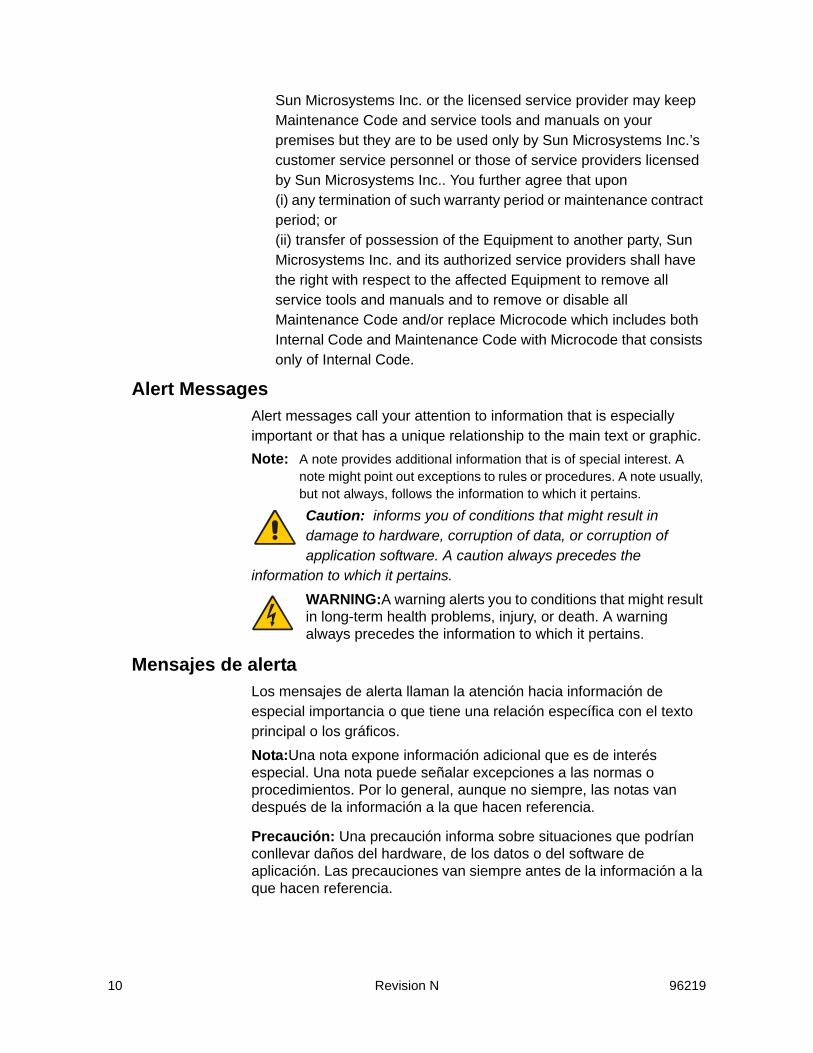
Sun Microsystems Inc. or the licensed service provider may keep Maintenance Code and service tools and manuals on your premises but they are to be used only by Sun Microsystems Inc.’s customer service personnel or those of service providers licensed by Sun Microsystems Inc.. You further agree that upon (i) any termination of such warranty period or maintenance contract period; or (ii) transfer of possession of the Equipment to another party, Sun Microsystems Inc. and its authorized service providers shall have the right with respect to the affected Equipment to remove all service tools and manuals and to remove or disable all Maintenance Code and/or replace Microcode which includes both Internal Code and Maintenance Code with Microcode that consists only of Internal Code.
Alert MessagesAlert messages call your attention to information that is especially important or that has a unique relationship to the main text or graphic.Note: A note provides additional information that is of special interest. A
note might point out exceptions to rules or procedures. A note usually, but not always, follows the information to which it pertains.
Caution: informs you of conditions that might result in damage to hardware, corruption of data, or corruption of application software. A caution always precedes the
information to which it pertains.WARNING:A warning alerts you to conditions that might result in long-term health problems, injury, or death. A warning always precedes the information to which it pertains.
Mensajes de alertaLos mensajes de alerta llaman la atención hacia información de especial importancia o que tiene una relación específica con el texto principal o los gráficos.Nota:Una nota expone información adicional que es de interés especial. Una nota puede señalar excepciones a las normas o procedimientos. Por lo general, aunque no siempre, las notas van después de la información a la que hacen referencia.
Precaución: Una precaución informa sobre situaciones que podrían conllevar daños del hardware, de los datos o del software de aplicación. Las precauciones van siempre antes de la información a la que hacen referencia.

96219 Revision N 11
Advertencia: Una advertencia llama la atención sobre condiciones que podrían conllevar problemas de salud crónicos, lesiones o muerte. Las advertencias van siempre antes de la información a la que hacen referencia.
Related DocumentsThe following publications comprise the SVA document set available to Sun Microsystems Inc. customers.Shared Virtual Array (SVA) SubsystemNote: The book part numbers changed. The old numbers are shown in parenthesis. • StorageTek Shared Virtual Array (SVA) V2X/V2X2 Introduction
96216 (MO9135)• StorageTek Shared Virtual Array (SVA) V2X/V2X2 Operation and
Recovery 96217 (MO9137) • StorageTek Shared Virtual Array (SVA) V2X/V2X2 Planning 96218
(MO9136) • StorageTek Shared Virtual Array (SVA) V2X/V2X2 Reference
96219 (MO9139) • StorageTek Shared Virtual Array (SVA) V2X/V2X2 System
Assurance 96220 (MO9138) • StorageTek Shared Virtual Array (SVA) V2X/V2X2 System
Assurance Tables 96223 (MO9169) • StorageTek Shared Virtual Array (SVA) V2X/V2X2 General
Information 96221 (MO9134)• StorageTek Shared Virtual Array (SVA) V2X/V2X2 Peer-to-Peer
Copy Configuration User’s Guide 96225 (MO9211)Shared Virtual Array Administrator (SVAA) for OS/390• SVAA for OS/390 Configuration and Administration PN 3112905xx• SVAA for OS/390 Reporting PN 3112906xx• SVAA for OS/390 Installation, Customization, and Maintenance PN
3112908xx• SVA SnapShot for OS/390 Installation, Customization, and
Maintenance PN 3112913xxShared Virtual Array Administrator (SVAA) for VM• SVAA for VM Configuration and Administration PN 3134629xx• SVAA for VM Reporting PN 3134630xx• SVAA for VM Installation, Customization, and Maintenance PN
3134631xxShared Virtual Array Administrator (SVAA) for OS/390 and VM• SVAA for OS/390 and VM Messages and Codes PN 3112907xx
12 Revision N 96219
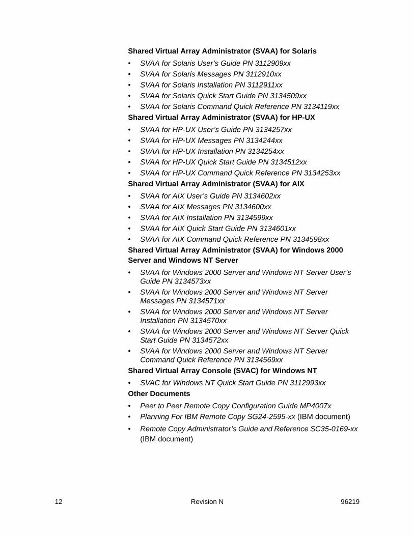
Shared Virtual Array Administrator (SVAA) for Solaris• SVAA for Solaris User’s Guide PN 3112909xx• SVAA for Solaris Messages PN 3112910xx• SVAA for Solaris Installation PN 3112911xx• SVAA for Solaris Quick Start Guide PN 3134509xx• SVAA for Solaris Command Quick Reference PN 3134119xxShared Virtual Array Administrator (SVAA) for HP-UX• SVAA for HP-UX User’s Guide PN 3134257xx• SVAA for HP-UX Messages PN 3134244xx• SVAA for HP-UX Installation PN 3134254xx• SVAA for HP-UX Quick Start Guide PN 3134512xx• SVAA for HP-UX Command Quick Reference PN 3134253xxShared Virtual Array Administrator (SVAA) for AIX• SVAA for AIX User’s Guide PN 3134602xx• SVAA for AIX Messages PN 3134600xx• SVAA for AIX Installation PN 3134599xx• SVAA for AIX Quick Start Guide PN 3134601xx• SVAA for AIX Command Quick Reference PN 3134598xxShared Virtual Array Administrator (SVAA) for Windows 2000 Server and Windows NT Server• SVAA for Windows 2000 Server and Windows NT Server User’s
Guide PN 3134573xx• SVAA for Windows 2000 Server and Windows NT Server
Messages PN 3134571xx• SVAA for Windows 2000 Server and Windows NT Server
Installation PN 3134570xx• SVAA for Windows 2000 Server and Windows NT Server Quick
Start Guide PN 3134572xx• SVAA for Windows 2000 Server and Windows NT Server
Command Quick Reference PN 3134569xxShared Virtual Array Console (SVAC) for Windows NT• SVAC for Windows NT Quick Start Guide PN 3112993xxOther Documents• Peer to Peer Remote Copy Configuration Guide MP4007x• Planning For IBM Remote Copy SG24-2595-xx (IBM document)• Remote Copy Administrator’s Guide and Reference SC35-0169-xx
(IBM document)
96219 Revision N 13
Viewing and Printing Web-Based Electronic DocumentsPublications listed in “Related Documents” can be viewed and printed from the Sun Microsystems Inc. Customer Resource Center (CRC) Web site at:http://www.support.storagetek.com
History of ChangesRev A – Initial release. September, 2002.Rev B – Second release. December, 2002
Minor changes involved edits and corrections. Major changes include:
- Added “Low Capacity FSC 3E41 Messages” section to chapter four.
Rev C – Third release. March, 2003. Minor changes involving edits and corrections.Rev D – Fourth release. March, 2003. Minor changes involving edits and corrections.Rev E – Fifth release. May, 2003. Minor changes involving edits and corrections.Rev F – Sixth release. December, 2003. Minor changes involving edits and corrections.Rev G – Seventh release. April, 2004. Minor changes involving edits and corrections.Rev H – Eighth release. February, 2005. Minor changes involving edits and corrections.Rev J – Nineth release. December 2005. Minor changes and corrections. Rev K – Tenth release. May 2006. Minor changes and corrections. Rev L – Eleventh release. June 2006. Minor changes and edits.Rev M – Twelfth release. Late July 2006. Minor changes and corrections. Rev N – Thirteenth release. November 2006. Minor changes and corrections.

14 Revision N 96219

96219 Revision N 15
1Addressing, Commands, and Status
AttachmentsSun Microsystems’s advanced Shared Virtual Array (SVA®) attaches to all IBM 370 equivalent data streaming channel architectures including IBM or compatible 30XX, 43XX, 9370, and ES/9000 series CPUs. The SVA also supports ESCON channels with data transfer rate of 17 megabytes per second.
Channel AddressingAt the OEMI channel interface to a host CPU, SVA presents a functional device image of one to sixteen 3990s operating in DLSE mode and supporting a total of up to 4096 functional 3380 and/or 3390 devices. Up to 1365 3390-9 devices can be defined. The SVA supports 3380J, 3380K, 3380KE, 3390-1, 3390-2, 3390-3, and 3390-9 device emulation. The functional device exhibits the external characteristics of the DASD device type that it emulates. The SVA does not impose limitations on intermixing functional device types within the subsystem configuration. However, host operating system limitations for intermixing device types apply to the SVA.Note: All devices referred to in this chapter are functional devices unless
otherwise noted.
Subsystem IdentifierEach functional storage control unit that the SVA emulates must have a unique subsystem identifier (SSID). A SSID is a hexadecimal number (up to 4 digits) assigned by the user that identifies the functional storage control unit.
Functional Device IdentifierEach functional 3380 or 3390 device that SVA emulates must have a unique functional device identifier (FDID). A FDID is an integer from 0 through 4095 that is assigned by the subsystem.

16 Revision N 96219
The base functional device identifier (BFDID) is the FDID of the lowest (base) interface address on a given channel.
Interface Device IdentifierThe SVA also maintains an interface device identifier (IDID). The IDID is a combination of the control unit cluster identifier, the channel port identifier, and the 8-bit address that is present on the interface bus lines at initial selection. The IDID uniquely identifies all of the addresses that can be presented to the subsystem at the OEMI channel interfaces. There are potentially 8192 unique IDs per subsystem.
Channel Address ConfigurationWhen configuring an SVA subsystem, each channel is assigned a BFDID and a range of interface addresses, which is specified by the BIDID and the address range. In this way, the subsystem constructs an address map from the OEMI interface to a specific functional device. This addressing scheme supports all requirements for DASD controllers.When configuring SVA, the following rules apply to the value of the BIDID and the BFDID:• They must be zero or a multiple of the address range• They cannot be greater than 248• The sum of the BIDID and the address range cannot exceed 4096 • The sum of the BFDID and the address range cannot exceed 4096.When configuring SVA, the rules for assigning the channel address range are:• Each channel interface may have only one address range specified• The number of addresses in the address range must be 8, 16, 32,
64, 128, 256, 512 or 1024 (decimal).Table 1 on page 17 demonstrates the correlation between the number of addresses configured in the subsystem and the acceptable address ranges (in hexadecimal).
I/O Channel InterfaceThe SVA completes initial selection within the times specified by the IBM System/360 and System/370 I/O Interface Channel to Control Unit Original Equipment Manufacturer’s Information. Initial selection is measured from the rise of Select Out (with Address Out up) to the rise

96219 Revision N 17
of Status In, and only includes time contributed by the Controller. Initial selection typicallycompletes within the following time frames:• 85 microseconds for control units with one to eight channels per
cluster• 170 microseconds for control units with nine to 16 channels per
cluster.Propagation of Select Out may be delayed up to 25 microseconds for channel-initiated selections and up to 30 microseconds for Controller-initiated selections.
Table 1 Channel Addressing (Maximum 4096 Configurable)
Number of Continuous Addresses dec hex
Number of Valid Base IDID/FDIDs Valid Base IDID/FDIDs (hexadecimal)
8 8 128 000 008 010 018 020 028 ... 390 3980A0 0A8 0B0 0B8 0C0 0C8 0D0 0D8 0E0 0E8 0F0 0F81A0 1A8 1B0 1B8 1C0 1C8 1D0 1D8 1E0 1E8 1F0 1F82A0 2A8 2B0 2B8 2C0 2C8 2D0 2D8 2E0 2E8 2F0 2F83A0 3A8 3B0 3B8 3C0 3C8 3D0 3D8 3E0 3E8 3F0 3F8
16 10 64 000 010 020 030 ... 3900A0 0B0 0C0 0D0 0E0 0F0 1A0 1B0 1C0 1D0 1E0 1F02A0 2B0 2C0 2D0 2E0 2F0 3A0 3B0 3C0 3D0 3E0 3F0
32 20 32 000 020 040 060 ... 3800A0 0C0 0E0 1A0 1C0 1E0 2A0 2C0 2E0 3A0 3C0 3E0
64 40 16 000 040 080 100 140... 3800A0 1A0 2A0 3A0
128 80 8 000 080 100 180 200 280 300 280
256 100 4 000 100 200 300
512 200 2 000 200
1024 400 1 000
Note:• Maximum 1024 channel addressing applies ONLY to SRLs ≥ K05.00.xx• Only decimal address ranges are displayed on subsystem operator panels.
18 Revision N 96219
Processing CommandsAsynchronous Operations
Certain sub-commands of the Set Subsystem Mode (SSM) command and certain orders of the Perform Subsystem Function (PSF) command specify operations that potentially take more than 15 seconds to complete. By default, these sub-command and orders are processed asynchronously (i.e. channel end and device end status are presented before the specified operation completes). Exception: the PSF Commit order can be specified to be synchronous or asynchronous.In processing asynchronous commands, the host program may or may not require that a completion message be returned to the channel. If the control unit receives an asynchronous command with the Message Required bit set in the command parameters, it assigns a message ID to the operation, presents channel end and device end status to the channel, and continues processing the requested operation asynchronously.If the Message Required bit is set in the Set Subsystem Mode or Perform Subsystem Function command parameters and a Read Message ID (RMID) command is not chained from the SSM or PSF command, then a completion message does not get returned to the channel.The RMID command retrieves the message ID assigned to the asynchronous operation. If the operation is completed before the RMID command is processed, the message ID in the data returned for the RMID command is zero.If an RMID command was received in the chain that specified the asynchronous operation, and the operation was not complete when the RMID was processed, the Controller presents unsolicited attention (80) status, when the operation is complete, to the channels in the path group of the channel that the asynchronous operation request was received on. The first channel that responds to the attention status receives an Attention Message that contains the completion status of the operation.The host responds to the attention status with the following chain:• Suspend Multipath Reconnection (recommended on an MVS
system)• PSF with a Prepare for Read Subsystem Data order with an
Attention Message suborder (03)

96219 Revision N 19
• Read Subsystem Data (RSSD).This chain can be used to query the completion status of the asynchronous operation before the attention status is presented.The Attention Message returned indicates the completion status of the operation. The completion status field of the Attention Message indicates operation is “pending” until it has successfully completed, completed with errors, or failed.
Channel Path Group IDThe channel path group ID contains the channel path ID (CHPID) for a channel. The channel path group ID also identifies the system control program that governs the channel and allows channel paths with the same channel path group ID to be grouped together, thus defining dynamic path reconnect.When the command processor executes a set path group ID command, a channel path group ID for the channel path is established. When the channel path group ID for a new channel path matches a previously defined channel path group ID, it is grouped with the previously defined channel(s). Only a system reset or channel disable on a channel clears the channel path group ID value for that channel.
Channel Exception ConditionsSystem Reset Processing
The host initiates system reset to reset all operations, status, mode settings, and allegiances associated with the channel path and all attached devices.In a system reset, channel interface hardware detects the system reset, automatically inactivates operational-in, and sends an interrupt to the control unit. The control unit microcode processes the interrupt and allows the channel to accept another system I/O to the point of presenting initial status. Then the microprocessor holds all subsequent channel operations until the system reset is completely processed, or it moves the operation to an available channel in the same channel path group. However:• If a channel operation is in progress when the channel receives the
system reset command, the control unit attempts to continue processing the operation until it reaches a normal end.
• If the resetting channel path is grouped with other channel paths, its channel path group ID is cleared and is removed from the channel path groupings for all of the allied functional devices.

20 Revision N 96219
• If the resetting channel path is the only channel path available to a device, and if the device is reserved to an operation that is part of a chain of operations that are already in progress, the system reset command breaks the chain. However, if the resetting channel is a member of a path group and the chained operation was in the disconnected state when the reset was received, the chained operation continues on another member of the path group.
• If the resetting channel path has a device reserved to it, and if it is the only channel path to that device, the device is released from the reserved condition. If the resetting channel path is a member of a path group, the device remains reserved to the other members of the path group.
Selective Reset ProcessingWhen the host channel detects certain equipment malfunctions (such as a Controller that presents an unexpected internal error while connected to the channel), it initiates selective reset processing. When Controller hardware detects the selective reset, it aborts the specific sequence in progress, and sets a selective reset condition. When control unit microcode detects the selective reset, it completes selective reset processing.The way that selective reset affects a channel path and its associated device depends on the circumstances.• Any operations in progress are allowed to complete to a normal
ending point, before selective reset processing begins.• Device busy is presented to any channel path of a different path
group that attempts to select the device during selective reset processing.
• If status is pending or is stacked on the resetting channel, the status is cleared (even if there is an available channel path in the same path group).
• If selective reset is received on one channel path while the device is connected to another channel path, selective reset has no effect.
• Selective reset has no effect on any path groupings or device reserve conditions that exist in the control unit at the time of the reset.
Interface Disconnect ProcessingIn an interface disconnect, a host channel signals the Controller to end the execution of the operation in progress and to disconnect from the channel. When channel hardware detects the interface disconnect, it
96219 Revision N 21
inactivates operation-in and sets a bit to indicate the interface disconnect condition.The way that interface disconnect affects operations in progress depends on the circumstances.• If an operation is in progress, the Controller allows the operation to
continue to normal completion.• If a data transfer operation from the host is in progress, data
transfer hardware automatically pads the rest of the transfer with zeros until the end of transfer interrupt indicates that the data transfer is completed.
• If a data transfer to the host is in progress, the rest of the data transfer operation is scrapped until an end of transfer interrupt indicates that the data transfer is complete. If ending status is owed to the host for the operation, the Controller initiates a selection sequence to present the status.
Owed Device EndWhen a channel attempts to select a device that is not currently available to its selection sequence (when the device is busy processing another channel operation for a different path group), the owed device end bit is set for the device. Then, when the device is no longer busy, the Controller initiates the selection and presents the owed device end status to notify the host that the device is available for processing.
Channel Error ManagementThis section describes some of the methods that may be employed as part of a channel path error recovery process.
Channel Command RetryThe Controller may request that the host retry a previously issued command. The Controller calls for a channel command retry (CCR) when it seeks to recover from a temporary error condition or when certain conditions prevented the execution of the command.
Disconnect-inWhen the Controller detects an internal error, it may issue a disconnect-in to the specified channel, which causes the channel to undergo a selective reset. Two possible situations exist:• If operation-in is active to the host, disconnect-in is asserted on the
current channel path. A 12-second time-out is initiated. If the channel path fails to respond with either selective or system reset
22 Revision N 96219
within 12 seconds, the Controller performs an internal selective reset, which clears the pending device status and returns the device to its pre-existing available or reserved status.
• If the device is not connected, the channel reconnects to the device, and then disconnect-in is asserted. A 14-second time-out period is initiated. If the channel path fails to respond to request-in within the time-out period, the time-out conditions are disabled.
Disconnected Device Status Time-outTo ensure that the host receives disconnected device status in a timely manner, the Controller monitors the progress of disconnected status. When a request to present disconnected status is initiated, a bit is set thatindicates that the device must present disconnected status. When the Controller determines that a device has not experienced this device specific bit set before, it sets another device specific bit that indicates that the device should present disconnected status and reset the device specific bits by the next time the disconnected device status is queried. If despite these efforts, the device has not presented disconnected device status, the Controller initiates an internal selective reset. The internal reset clears the pending device status and returns the device to its pre-existing available or reserved status.
Path ControlDynamic Path Reconnect
In an XA or ESA environment, V2X SVA supports dynamic path reconnect. Dynamic path reconnect allows the subsystem to reconnect to the host system through any channel of a logically defined group rather than limiting reconnection to the channel that initiated the operation.Dynamic path reconnect is enabled by a system control program that defines the logical group of channels. When the device is ready to reconnect to the host system, any available channel in that group may transfer the data to the host.
Single Path ModeIn single path mode, when a channel path obtains device selection, that device is now locked in to connecting or reconnecting to the host via that one channel path.

96219 Revision N 23
Single path mode is the default mode for the subsystem. On powering up the subsystem, all channel paths are set to operate in single path mode. Single path mode is also designated in the following conditions:• When a Set Path Group ID command specifying single path mode
is received for a channel path • When a system reset is received for a channel path • When a channel is disabled, it is set to resume operations in single
path mode.Single path mode is reset when a set path group ID command specifying multipath mode is received for a channel path. This command clears the single path mode for the particular channel path that receives the command.
Multipath ModeIn multipath mode, when a channel path initiates a device selection and the device disconnects from the channel, it may reconnect to any channel path that is part of the same path group as the initiating channel path.The multipath mode is enabled by resetting a bit in the single path mode data structure for the channel path. When in multipath mode, grouping applies to both device reservation and reconnection.
Path Control CommandsThis section describes the path control commands and how they are processed in the SVA.
Suspend Multipath ReconnectionThe host issues the Suspend Multipath Reconnection command to facilitate recovery operations when the subsystem is in the multipath mode. This command suspends the multipath mode for the channel path that receives the command. When successfully completed, channel and device end status are presented to the host, and multipath mode is suspended until the host accepts ending status for the command chain.The Suspend Multipath Reconnection command has no effect on device reservation or channel path groupings, and is not valid in the domain of a Locate Record or Locate Record Extended command.
Set Path Group IDThe Set Path Group ID command controls the allocation and de-allocation of individual channel paths into logical groups. This

24 Revision N 96219
command sends 12 bytes of data from the host to the Controller. The Controller then returns channel and device end status to the host.The Set Path Group ID command must be the only command in the channel program. If this command is chained from another command, the Set Path Group ID command is rejected and unit check status is presented to the host.
Sense Path Group IDThe host issues the Sense Path Group ID command to obtain the channel path group ID value and the addressed device’s group status for the channel path receiving the command. When executed, the Sense Path Group ID command sends path group data to the host, and then presents channel and device end status to the host.The Sense Path Group ID command is executed even if the device is busy or not ready, and the command must be the only command in the channel program. If this command is chained to any other command, the Sense Path Group ID command is rejected, and unit check status is presented.
Device ReserveThe host issues a Device Reserve command to obtain the long term allegiance of a specified device. As long as a command previous to the Device Reserve command did not receive a unit check, the Controller sends the host unsolicited sense data for the specified device. Then channel and device end are presented as status to the host. However, the Device Reserve command is not executed if the Controller determines that the device is busy with a previous operation or that the device is reserved to another channel or group of channels. Instead, owed device end is queued on the channel path, and device busy is presented to the host as status. If the device is available for
Table 2 Set Path Group ID Control Byte 0
Bit Value Definition
0 01
Single path mode is specifiedMultiple path mode is specified
1-2 00011011
Establish path groupDisband path groupResign from path groupInvalid
3-7 00000 These bits must all be zero
96219 Revision N 25
processing, the Device Reserve command begins even if the device is not ready.When the Device Reserve command is successfully executed, only the channel path or path group specified by the reserve command may access the device.The Device Reserve command must always be the first command in a channel command program. If a command precedes it, the Device Reserve command is rejected and unit check status is presented to the host.When a device is reserved, it remains reserved until one of the following occurs to clear it:• A Device Release command is successfully executed on any
member of a path group.• An Unconditional Reserve command is successfully executed on a
channel path that is not a member of the path group that holds the device reserve.
• A system reset or channel disable is successfully executed on the channel path (in single path mode).
If a device is reserved to a path group and system reset or a channel disable occurs on one of the members, the device remains reserved to the remaining members.
Device ReleaseThe host issues a Device Release command to release a specified device from the reserved status. As long as a command previous to the Device Release command did not receive a unit check, the control unit sends the host unsolicited sense data for the specified device. Then channel and device end are presented as status to the host.The Device Release command is not executed if the device is busy with a previous operation. In this case, an owed device end is queued for the channel path that initiated the operation, and device busy status is presented to the host. However, if the device is available for processing, the Device Release command begins even if the device is not ready.When successfully executed, the Device Release command releases the device from the reserve status.The Device Reserve command must be the first command in a channel command program. If this command is preceded in a channel program by a define extent, space count, or set file mask command,
26 Revision N 96219
the Device Release command is rejected and unit check status is presented to the host.
Unconditional ReserveThe host issues an Unconditional Reserve command to obtain the long term allegiance of a specified device. As long as a command previous to the Unconditional Reserve command did not receive a unit check, the control unit sends the host unsolicited sense data for the specified device. Then channel and device end are presented as status to the host. The Unconditional Reserve command begins even if the device is busy, not ready, or reserved by another channel path or path group.When successfully executed, the Unconditional Reserve command reserves a device to the channel path or path group that executes the command, regardless of any other prior device reserve conditions. If the device was reserved by another channel path or path group, that device reservation is reset and the device is reserved by the channel path or path group that executed the Unconditional Reserve command.The Unconditional Reserve command must be the first command in a channel command program. If a command precedes it, the Unconditional Reserve command is rejected and unit check is presented to the host.
Reset AllegianceThe Reset Allegiance command terminates a device’s allegiance (contingent or implicit) to a channel path or channel path group.The Reset Allegiance command must be the first command executed in a channel command program. If any command has preceded this command, the Reset Allegiance command is rejected and unit check status is presented to the host.The Reset Allegiance command executes even if the device is busy or not ready. In its execution, the device’s status is tested to determine if it is allied or reserved to another path group. The Reset Allegiance command may encounter three situations:• If the device is reserved to another channel or path group, the
Reset Allegiance command returns reservation and allegiance data but does not alter any device allegiances. Any command that is chained to the Reset Allegiance command is rejected, and unit check status is presented.
• If the device is not reserved but has an allegiance (implicit or contingent) to another path group, the Reset Allegiance command terminates that allegiance.
96219 Revision N 27
• If the device is not reserved by any other channel path or is reserved to the channel path or path group that issued the Reset Allegiance command, all CCW chains are terminated, status for the CCW chain is cleared, and reservation and allegiance data is sent.

28 Revision N 96219
96219 Revision N 29
2Command Description
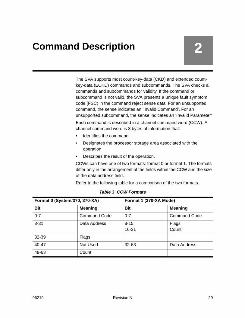
The SVA supports most count-key-data (CKD) and extended count-key-data (ECKD) commands and subcommands. The SVA checks all commands and subcommands for validity. If the command or subcommand is not valid, the SVA presents a unique fault symptom code (FSC) in the command reject sense data. For an unsupported command, the sense indicates an ‘Invalid Command’. For an unsupported subcommand, the sense indicates an ‘Invalid Parameter’Each command is described in a channel command word (CCW). A channel command word is 8 bytes of information that:• Identifies the command• Designates the processor storage area associated with the
operation• Describes the result of the operation.CCWs can have one of two formats: format 0 or format 1. The formats differ only in the arrangement of the fields within the CCW and the size of the data address field.Refer to the following table for a comparison of the two formats.
Table 3 CCW Formats
Format 0 (System/370, 370-XA) Format 1 (370-XA Mode)Bit Meaning Bit Meaning0-7 Command Code 0-7 Command Code
8-31 Data Address 8-1516-31
FlagsCount
32-39 Flags
40-47 Not Used 32-63 Data Address
48-63 Count
30 Revision N 96219
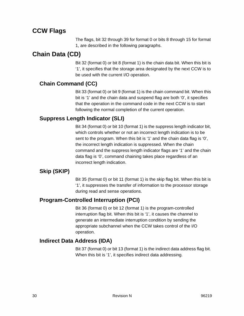
CCW FlagsThe flags, bit 32 through 39 for format 0 or bits 8 through 15 for format 1, are described in the following paragraphs.
Chain Data (CD)Bit 32 (format 0) or bit 8 (format 1) is the chain data bit. When this bit is ‘1’, it specifies that the storage area designated by the next CCW is to be used with the current I/O operation.
Chain Command (CC)Bit 33 (format 0) or bit 9 (format 1) is the chain command bit. When this bit is ‘1’ and the chain data and suspend flag are both ‘0’, it specifies that the operation in the command code in the next CCW is to start following the normal completion of the current operation.
Suppress Length Indicator (SLI)Bit 34 (format 0) or bit 10 (format 1) is the suppress length indicator bit, which controls whether or not an incorrect length indication is to be sent to the program. When this bit is ‘1’ and the chain data flag is ‘0’, the incorrect length indication is suppressed. When the chain command and the suppress length indicator flags are ‘1’ and the chain data flag is ‘0’, command chaining takes place regardless of an incorrect length indication.
Skip (SKIP)Bit 35 (format 0) or bit 11 (format 1) is the skip flag bit. When this bit is ‘1’, it suppresses the transfer of information to the processor storage during read and sense operations.
Program-Controlled Interruption (PCI)Bit 36 (format 0) or bit 12 (format 1) is the program-controlled interruption flag bit. When this bit is ‘1’, it causes the channel to generate an intermediate interruption condition by sending the appropriate subchannel when the CCW takes control of the I/O operation.
Indirect Data Address (IDA)Bit 37 (format 0) or bit 13 (format 1) is the indirect data address flag bit. When this bit is ‘1’, it specifies indirect data addressing.

96219 Revision N 31
Suspend (S)Bit 38 (format 0) or bit 14 (format 1) is the suspend flag bit. When this bit is ‘1’, it suspends the processing of the channel program.
Flag bit 39 or 15Except for a Transfer in Channel (TIC) command, flag bit 39 (format 0) or bit 15 (format 1) must be ‘0’. For a TIC command, this flag bit is ignored.
Exception ConditionsThe command descriptions found in this chapter include the criteria for checking and reporting I/O program exceptions. Exception conditions are identified by exception type and format or by message codes. “24-Byte Compatibility Sense Data” on page 151, provides more information about how exception conditions are reported. Exception conditions are described in order of priority unless otherwise specified. Command reject with format 0, message 1 is the highest priority exception.Table 4 on page 34 lists the commands that the SVA accepts and restrictions on those commands. Any command issued that is not listed in this table is rejected and the sense data returned is format 0, message 1. Any command issued that does not adhere to the stated restrictions is rejected and the sense data returned is format 0, message 1.
Multitrack OperationsMultitrack operations are those in which the specified operation continues past the end of a functional track. In such cases, the storage path advances to the next functional track and continues the operation.Multitrack operations are either in or outside of a Locate Record or Locate Record Extended domain.
In a Locate Record or Locate Record Extended DomainMost data transfer operations (read or write operations between the storage path and the device) in a Locate Record or Locate Record Extended domain are multitrack operations.An operation is a multitrack operation when the Locate Record operation is determined to be explicitly multitrack or when bit 0 of the data transfer command is ‘1’.When a valid end-of-track is detected during a data transfer operation between the storage path and the functional device (other than a Read

32 Revision N 96219
Any or Write Any operation) and multitrack mode is specified, the following conditions apply to the operation:• If the next functional track is in the defined extent, the operation
continues at that functional track. If the current functional track is the last track of the cylinder, the operation continues at the first functional track of the next cylinder, provided it is a primary cylinder. If the cylinder is not a primary cylinder, the operation ends and unit check status (command reject and file protected) is presented.
• If the next functional track of the cylinder is not in the defined extent, the operation is terminated and unit check status (file protected) is presented.
• If the next functional track of the cylinder in the defined extent is defective, the operation continues on an alternate functional track assigned by the Controller. If an alternate functional track is not assigned or if the assignment is not valid, the operation is terminated and unit check status (command reject) is presented.
When a valid end-of-track is detected during a Read Any or Write Any operation, the operation continues on the same functional track.
Outside the Locate Record or Locate Record Extended DomainWhen an operation is outside the Locate Record or Locate Record Extended domain and bit 0 in the command code is ‘1’, all read and search operations are multitrack operations.When a read or search command returns to index or when an end-of-track is detected while orienting to a count area, the multitrack operation continues uninterrupted. Multitrack operations do not continue if:• The file mask inhibit (bits 3 and 4) are set. The operation is
terminated and unit check status (file protected) is presented.• The next functional track is not in the defined extent. The operation
is terminated and unit check status (file protected) is presented.• The current functional track is the last track in the functional
cylinder. The operation is terminated and unit check status (end-of-cylinder) is presented.
Command Suspension or ResumptionThe SVA may suspend processing a command or command chain and resume the process at a later time, possibly with a different microprocessor. The SVA may do this to avoid tying up. Certain
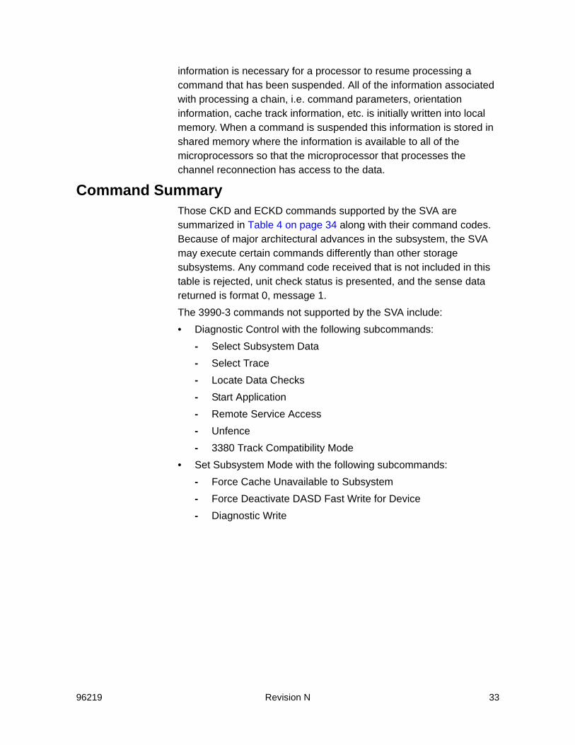
96219 Revision N 33
information is necessary for a processor to resume processing a command that has been suspended. All of the information associated with processing a chain, i.e. command parameters, orientation information, cache track information, etc. is initially written into local memory. When a command is suspended this information is stored in shared memory where the information is available to all of the microprocessors so that the microprocessor that processes the channel reconnection has access to the data.
Command SummaryThose CKD and ECKD commands supported by the SVA are summarized in Table 4 on page 34 along with their command codes. Because of major architectural advances in the subsystem, the SVA may execute certain commands differently than other storage subsystems. Any command code received that is not included in this table is rejected, unit check status is presented, and the sense data returned is format 0, message 1.The 3990-3 commands not supported by the SVA include:• Diagnostic Control with the following subcommands:
- Select Subsystem Data- Select Trace- Locate Data Checks- Start Application- Remote Service Access- Unfence- 3380 Track Compatibility Mode
• Set Subsystem Mode with the following subcommands:- Force Cache Unavailable to Subsystem- Force Deactivate DASD Fast Write for Device- Diagnostic Write

34 Revision N 96219
The SVA executes ESCON-related commands in the same manner that other non-ESCON capable subsystems do.
Table 4 Summary of the SVA Channel Commands
Command MnemonicHex Code
Multitrack Command
Addressing and Control CommandsDefine ExtentLocate RecordLocate Record ExtendedSeekSeek CylinderSeek HeadRecalibrateSet File MaskSet SectorRead SectorRead Device Characteristics
DXLRLRESKSKCSKHDRCALSFMSSRSRDC
63474B070B1B131F232264
Read CommandsRead Special Home AddressRead Home AddressRead Record ZeroRead Count, Key, and DataRead Key and DataRead DataRead CountRead Multiple Count, Key, and DataRead TrackRead Initial Program Load (IPL)
RSHARHARRORCKDRKDRDRCRMCKDRTRIPL
0A1A161E0E06125EDE02
9A969E8E8692
Search CommandsSearch Home Address EqualSearch ID EqualSearch ID HighSearch ID Equal or HighSearch Key EqualSearch Key HighSearch Key Equal or High
SHASIDESIDHSIDEHSKESKHSKEH
39315171294969
B9B1D1F1A9C9E9

96219 Revision N 35
Write CommandsWrite Special Home AddressWrite Home AddressWrite Record ZeroWrite Count, Key, and DataWrite Count, Key, and Data Next TrackWrite Update Key and DataWrite Key and DataWrite Update DataWrite DataErase
WSHAWHAWR0WCKDWCKDNTWUKDWKDWUDWDERAS
0919151D9D8D0D850511
Sense CommandsSenseSense ID
SNSSNSID
04E4
Path Control CommandsDevice ReserveDevice ReleaseUnconditional ReserveReset AllegianceSet Path Group IDSense Path Group IDSuspend Multipath Reconnection
RESRELURRSTASPIDSNIDSMR
B4941444AF345B
Subsystem CommandsSet Subsystem ModePerform Subsystem FunctionSense Subsystem StatusRead Subsystem DataRead Message ID
SSMPSFSNSSRSSDRMID
8727543E4E
Table 4 Summary of the SVA Channel Commands (Continued)
Command MnemonicHex Code
Multitrack Command

36 Revision N 96219
Status Presented To CommandsThe Status Presented To commands depends on the status of the subsystem and of the device addressed. Table 5 on page 37 summarizes the status presented to commands when the subsystem or device is in one of the conditions described in the following text.• State-change-pending The functional device or storage control is
performing an operation that exceeds the time for normal busy states.
• Busy status.• Device reserved The device is reserved to another interface as
the result of the processing of a Device Reserve command.• Channel end and device end split (Start I/O only) Channel end
has been presented, but device end has not been presented on this path group. Busy status is normally presented to a Start I/O.
• Device not available The device is not ready or is not installed.• Contingent allegiance The device and/or subsystem is in a
contingent allegiance state for another interface.• Chain unconditional reserved The device had allegiance to an
interface, and another interface issued an Unconditional Reserve command. The allegiance is broken and sense is built. If status is owed (if status and Unconditional Reserve is received on the same or different interface path or group) then unit check is added to owed status.- If the allegiance is explicit, unit check is presented to the next
initial selection (Start I/O).
Miscellaneous CommandsTest I/ONo-OperationRead and Reset Buffered LogDiagnostic ControlDiagnostic Sense/ReadDiagnostic WriteRead Configuration DataSpace CountRestore
TIONOPRRBFLDCTLDSNSRDWRTRCDSPCNTRSTOR
0003A4F3C473FA0F17
Table 4 Summary of the SVA Channel Commands (Continued)
Command MnemonicHex Code
Multitrack Command

96219 Revision N 37
- If implicit allegiance and Unconditional Reserve is received on another interface:
- Then unit check is presented to the next command in the chain during the chained reselection
- The command is allowed to complete (ending status is presented)
I. If it is the last command in the chain, the chain completes normally and the unit check is presented at the next Start I/O.
If contingent allegiance and Unconditional Reserve is received on another interface:
II. If device level allegiance and the Sense command are not received yet, the Sense command is unit checked at the next Start I/O, and allegiance is established again
III. If channel level allegiance and the Sense command are not received yet, the Sense command is accepted.
• Reset notify (Start I/O only) A system reset has been received. Unit check status is normally presented to the next Start I/O on the reset interface.
• Reset time-out A channel check condition was detected and the channel has not responded. Unit check status is normally presented to the next Start I/O from that channel, when a Start I/O of all other commands in the table is issued or if unit checked, as shown in the following table.
Table 5 Effect of Subsystem and Device Status on the Status Presented to Commands
Com
man
d M
nem
onic
Subsystem or Device Status
Stat
e-C
hang
ePe
ndin
g
(SIO
onl
y) B
usy
Dev
ice
Res
erve
d
Cha
nnel
End
/Dev
ice
End
Split
Dev
ice
Not
Ava
ilabl
ea
Con
tinge
ntA
llegi
ance
(on
adi
ffere
nt in
terf
ace)
Cha
in U
ncon
ditio
nal
Res
erve
d (a
llegi
ance
term
inat
ed)
(SIO
onl
y) R
eset
Not
ify
Res
et T
ime-
out
TIO Unit check
Busy Busy Busy Unit check Busy Unit check
Unit check
Unit check
NOP Accepted Busy Busy Busy Unit check Busy Unit check
Unit check
Unit check
SPID Accepted Accepted Accepted Accepted Accepted Accepted Accepted Unit check
Accepted

38 Revision N 96219
SNID Accepted Accepted Accepted Accepted Accepted Accepted Accepted Unit check
Accepted
UR Accepted Accepted Accepted Accepted Unit check Accepted Accepted Unit check
Accepted
RSTA Accepted Accepted Accepted Accepted Accepted Accepted Accepted Unit check
Accepted
RIPL Unit check
Busy Busy Busy Unit check Busy Unit check
Acceptedb
Accepted
RES Accepted Busy Busy Busy Unit checkc Busy Accepted Unit check
Accepted
REL Accepted Busy Busy Busy Unit checkc Busy Accepted Unit check
Accepted
SNSd Accepted Busy Busy Accepted Unit check Busy Unit check
Unit check
Accepted
SNSe Accepted Busy Accepted Accepted Accepted Accepted Accepted Accepted Accepted
SNSf Accepted Busy Accepted Accepted Accepted Accepted Unit check
Accepted Unit check
DCTL Unit check
Busy Accepted Busy Acceptedg Busy Unit check
Unit check
Unit check
SNSS Accepted Busy Accepted Busy Accepted Busy Unit check
Unit check
Unit check
RDC Accepted Busy Accepted Busy Accepted Busy Unit check
Unit check
Unit check
SNSID Accepted Busy Accepted Busy Accepted Accepted Unit check
Unit check
Unit check
RCD Accepted Busy Accepted Busy Accepted Busy Unit check
Unit check
Unit check
PSF Unit check
Busy Busy Busy Acceptedh Busy Unit check
Unit check
Unit check
RSSD Unit check
Busy Busy Busy Acceptedi Busy Unit check
Unit check
Unit check
RMID Unit check
Busy Busy Busy Acceptedj Busy Unit check
Unit check
Unit check
SSM Unit check
Busy Busy Busy Accepted Busy Unit check
Unit check
Unit check
Table 5 Effect of Subsystem and Device Status on the Status Presented to CommandsC
omm
and
Mne
mon
ic
Subsystem or Device Status
Stat
e-C
hang
ePe
ndin
g
(SIO
onl
y) B
usy
Dev
ice
Res
erve
d
Cha
nnel
End
/Dev
ice
End
Split
Dev
ice
Not
Ava
ilabl
ea
Con
tinge
ntA
llegi
ance
(on
adi
ffere
nt in
terf
ace)
Cha
in U
ncon
ditio
nal
Res
erve
d (a
llegi
ance
term
inat
ed)
(SIO
onl
y) R
eset
Not
ify
Res
et T
ime-
out

96219 Revision N 39
Addressing and Control CommandsBasic Address And Control Commands
The basic address and control commands are listed below. Refer to “Channel Commands and Parameter Information” on page 213 for information about how the SVA processes these commands as compared to the way an IBM 3990 handles them. For specific details of these commands, refer to the IBM manual IBM 3990 Storage Control Reference, GA32-0099.
SMR Accepted Busy Busy Busy Accepted Busy Unit check
Unit check
Unit check
All Others
Unit check
Busy Busy Busy Unit check Busy Unit check
Unit check
Unit check
a For the SVA, device not available indicates the functional device is not configured or it has been logically disabled.b The reset notification mark is reset.c Accepted if the functional device has been logically disabled. Unit checked if the functional device is not configured.d No contingent allegiance for this interface.e Contingent allegiance at the subsystem level for this interface.f Contingent allegiance at the device level for this interface.g Only the Diagnostic Initialize Subsystem order of the Diagnostic Control command is accept-ed.h Only the Discard, Prepare for Read Subsystem Data, and Set Interface Identifier orders of the Perform Subsystem Function command are accepted. Read Subsystem Data command is ac-cepted when chained from the Prepare for Read Subsystem Data order.i Only the Access Device in Unknown Condition order is accepted. The Diagnostic Initialize Subsystem order receives a unit check in ending status, except in one case: format D, message F, Reason ID. The exception was: issued to non-existent device (no config) accepted.j Accepted only if chained from the appropriate subcommand. Otherwise, the SVA issues a channel command retry and then unit check (intervention required) is presented.
Table 5 Effect of Subsystem and Device Status on the Status Presented to CommandsC
omm
and
Mne
mon
ic
Subsystem or Device Status
Stat
e-C
hang
ePe
ndin
g
(SIO
onl
y) B
usy
Dev
ice
Res
erve
d
Cha
nnel
End
/Dev
ice
End
Split
Dev
ice
Not
Ava
ilabl
ea
Con
tinge
ntA
llegi
ance
(on
adi
ffere
nt in
terf
ace)
Cha
in U
ncon
ditio
nal
Res
erve
d (a
llegi
ance
term
inat
ed)
(SIO
onl
y) R
eset
Not
ify
Res
et T
ime-
out
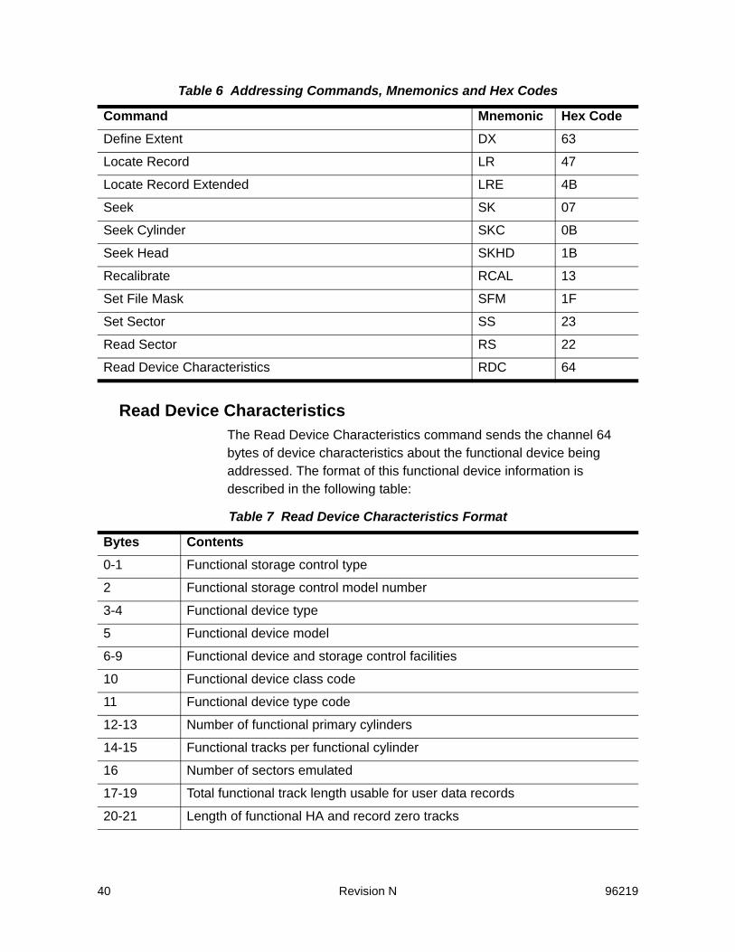
40 Revision N 96219
Read Device CharacteristicsThe Read Device Characteristics command sends the channel 64 bytes of device characteristics about the functional device being addressed. The format of this functional device information is described in the following table:
Table 6 Addressing Commands, Mnemonics and Hex Codes
Command Mnemonic Hex CodeDefine Extent DX 63
Locate Record LR 47
Locate Record Extended LRE 4B
Seek SK 07
Seek Cylinder SKC 0B
Seek Head SKHD 1B
Recalibrate RCAL 13
Set File Mask SFM 1F
Set Sector SS 23
Read Sector RS 22
Read Device Characteristics RDC 64
Table 7 Read Device Characteristics Format
Bytes Contents0-1 Functional storage control type
2 Functional storage control model number
3-4 Functional device type
5 Functional device model
6-9 Functional device and storage control facilities
10 Functional device class code
11 Functional device type code
12-13 Number of functional primary cylinders
14-15 Functional tracks per functional cylinder
16 Number of sectors emulated
17-19 Total functional track length usable for user data records
20-21 Length of functional HA and record zero tracks
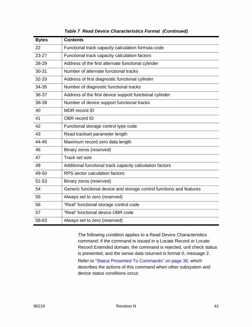
96219 Revision N 41
The following condition applies to a Read Device Characteristics command; if the command is issued in a Locate Record or Locate Record Extended domain, the command is rejected, unit check status is presented, and the sense data returned is format 0, message 2.Refer to “Status Presented To Commands” on page 36, which describes the actions of this command when other subsystem and device status conditions occur.
22 Functional track capacity calculation formula code
23-27 Functional track capacity calculation factors
28-29 Address of the first alternate functional cylinder
30-31 Number of alternate functional tracks
32-33 Address of first diagnostic functional cylinder
34-35 Number of diagnostic functional tracks
36-37 Address of the first device support functional cylinder
38-39 Number of device support functional tracks
40 MDR record ID
41 OBR record ID
42 Functional storage control type code
43 Read trackset parameter length
44-45 Maximum record zero data length
46 Binary zeros (reserved)
47 Track set size
48 Additional functional track capacity calculation factors
49-50 RPS sector calculation factors
51-53 Binary zeros (reserved)
54 Generic functional device and storage control functions and features
55 Always set to zero (reserved)
56 “Real” functional storage control code
57 “Real” functional device OBR code
58-63 Always set to zero (reserved)
Table 7 Read Device Characteristics Format (Continued)
Bytes Contents

42 Revision N 96219
Ending StatusThe storage path presents channel end and device end status when the data transfer operation is complete. The Read Device Characteristics (RDC) command resets the orientation of the storage path.
RDC Bytes 0 and 1Contain the four-digit functional storage control type number as four hexadecimal digits.
RDC Byte 2Identifies the functional storage control model number and the supported architecture. The active bits specify:
RDC Bytes 3 and 4Contain the four-digit functional device type number as four hexadecimal digits.
RDC Byte 5Contains the functional device model and features.
RDC Bytes 6 through 9Show the program-visible facilities in the functional device and the functional storage control.
Table 8 RDC Byte 2
Bits Meaning0-1 Architecture support
2 Non synchronous support
3 Not used
4 Cache information
5-7 Functional storage control model information
Table 9 RDC Byte 6
Bits Meaning0 Multiple burst ECC (always set to ’1’)
1 Subsystem supports Read Track operations in a Locate Record domain (always set to ’1’)
2 Reserved (always set to ’0’)
3 Subsystem supports Read operations in a Locate Record domain (always set to ’1’)
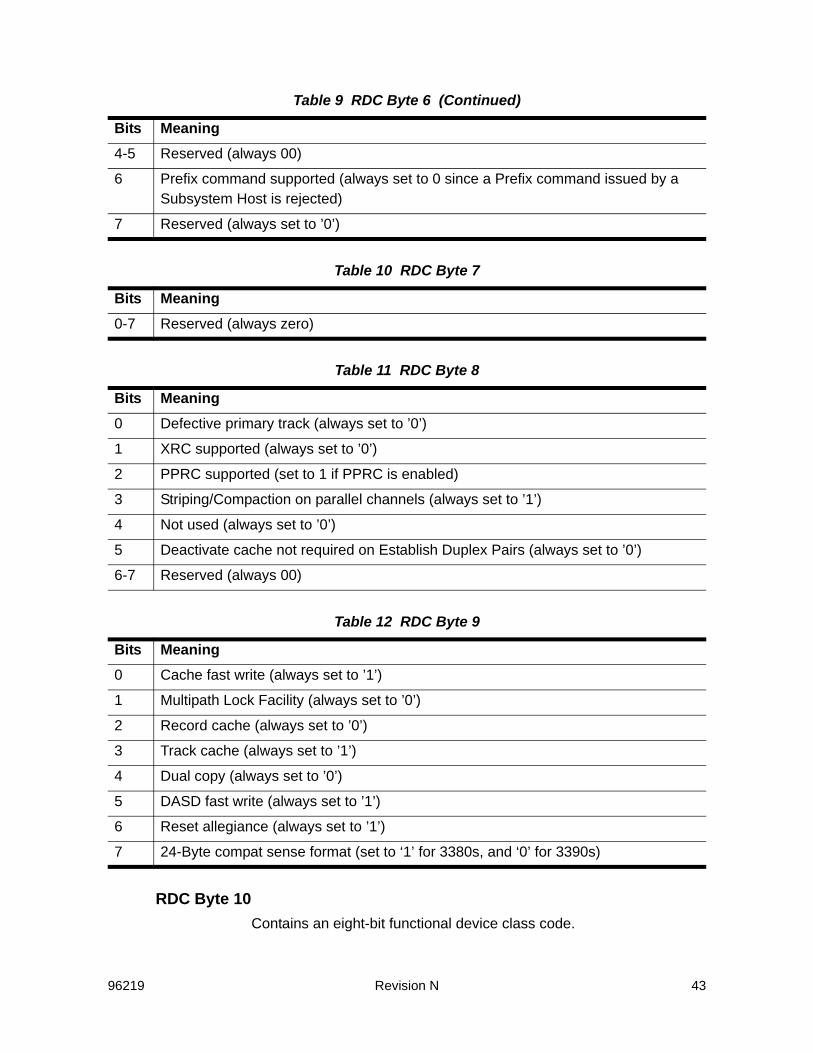
96219 Revision N 43
RDC Byte 10Contains an eight-bit functional device class code.
4-5 Reserved (always 00)
6 Prefix command supported (always set to 0 since a Prefix command issued by a Subsystem Host is rejected)
7 Reserved (always set to ’0’)
Table 10 RDC Byte 7
Bits Meaning0-7 Reserved (always zero)
Table 11 RDC Byte 8
Bits Meaning0 Defective primary track (always set to ’0’)
1 XRC supported (always set to ’0’)
2 PPRC supported (set to 1 if PPRC is enabled)
3 Striping/Compaction on parallel channels (always set to ’1’)
4 Not used (always set to ’0’)
5 Deactivate cache not required on Establish Duplex Pairs (always set to ’0’)
6-7 Reserved (always 00)
Table 12 RDC Byte 9
Bits Meaning0 Cache fast write (always set to ’1’)
1 Multipath Lock Facility (always set to ’0’)
2 Record cache (always set to ’0’)
3 Track cache (always set to ’1’)
4 Dual copy (always set to ’0’)
5 DASD fast write (always set to ’1’)
6 Reset allegiance (always set to ’1’)
7 24-Byte compat sense format (set to ‘1’ for 3380s, and ‘0’ for 3390s)
Table 9 RDC Byte 6 (Continued)
Bits Meaning

44 Revision N 96219
RDC Byte 11Contains an eight-bit functional device type code.
RDC Bytes 12 and 13Contain an unsigned, 16-bit binary value that indicates the number of primary cylinders on the functional device. The highest primary cylinder address on the device is one less than the value in Bytes 12 and 13.
RDC Bytes 14 and 15Contain an unsigned, 16-bit binary value that indicates the number of functional tracks in a functional cylinder. The highest valid functional track address in any functional cylinder is one less than the value in Bytes 14 and 15.
RDC Byte 16Contains an unsigned, eight-bit binary value that indicates the number of sectors in a track. The highest valid sector number for the device (excluding X’FF’) is one less than the value in Byte 16.
RDC Bytes 17 through 19Contain an unsigned, 24-bit binary value that indicates the total number of usable bytes on each functional track. This value is valid after the track has been formatted with a home address and a standard record zero. This value is the maximum number of bytes available for formatting user datarecords, and includes all space that the count areas occupy, and device dependent recording items (such as gaps and ECC bytes) that are associated with the records.Note: A set of user data records can be written on a functional track if the
sum of the space values of the records calculated by the formula specified in Byte 22 is equal to or less than the value in Bytes 17 through 19.
RDC Bytes 20 and 21Contain an unsigned, 16-bit binary value that indicates the total amount of bytes used for a home address and a standard record zero. This value includes the space occupied by device-dependent recording items (such as gaps and ECC bytes) that are associated with home address and record zero.
RDC Byte 22 Contains an unsigned, eight-bit binary value that specifies the formula to perform track capacity calculations for the device. When Byte 22 is
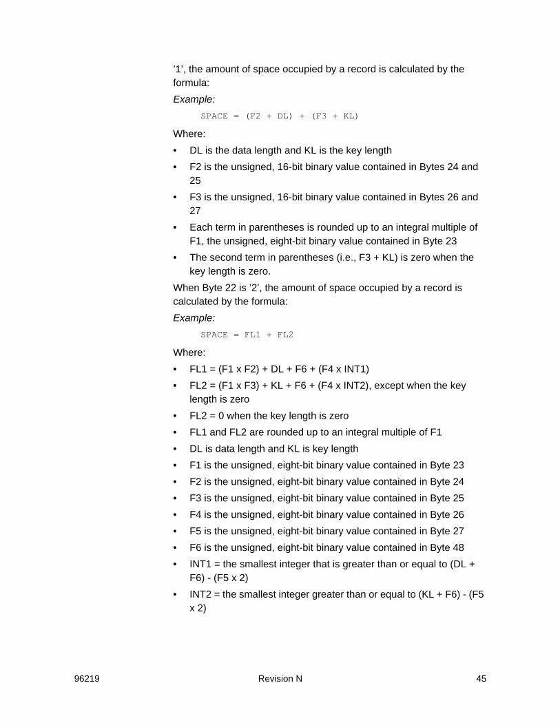
96219 Revision N 45
’1’, the amount of space occupied by a record is calculated by the formula:Example:
SPACE = (F2 + DL) + (F3 + KL)
Where:• DL is the data length and KL is the key length• F2 is the unsigned, 16-bit binary value contained in Bytes 24 and
25• F3 is the unsigned, 16-bit binary value contained in Bytes 26 and
27• Each term in parentheses is rounded up to an integral multiple of
F1, the unsigned, eight-bit binary value contained in Byte 23• The second term in parentheses (i.e., F3 + KL) is zero when the
key length is zero.When Byte 22 is ’2’, the amount of space occupied by a record is calculated by the formula:Example:
SPACE = FL1 + FL2
Where:• FL1 = (F1 x F2) + DL + F6 + (F4 x INT1)• FL2 = (F1 x F3) + KL + F6 + (F4 x INT2), except when the key
length is zero• FL2 = 0 when the key length is zero• FL1 and FL2 are rounded up to an integral multiple of F1• DL is data length and KL is key length• F1 is the unsigned, eight-bit binary value contained in Byte 23• F2 is the unsigned, eight-bit binary value contained in Byte 24• F3 is the unsigned, eight-bit binary value contained in Byte 25• F4 is the unsigned, eight-bit binary value contained in Byte 26• F5 is the unsigned, eight-bit binary value contained in Byte 27• F6 is the unsigned, eight-bit binary value contained in Byte 48• INT1 = the smallest integer that is greater than or equal to (DL +
F6) - (F5 x 2)• INT2 = the smallest integer greater than or equal to (KL + F6) - (F5
x 2)

46 Revision N 96219
RDC Bytes 23 through 27Contain the factors that are used in the functional track capacity calculation formulas. Refer to “RDC Byte 22” on page 44.
RDC Bytes 28 and 29Contain an unsigned, 16-bit binary value that is the address (CC) of the first functional cylinder that contains alternate functional tracks.
RDC Bytes 30 and 31Contain an unsigned, 16-bit binary value that is the number of alternate functional tracks on the functional device.
RDC Bytes 32 and 33Contain an unsigned, 16-bit binary value that is the address (CC) of the first functional cylinder that contains diagnostic tracks.
RDC Bytes 34 and 35Contain an unsigned, 16-bit binary value that is the number of diagnostic tracks on the device.
RDC Bytes 36 and 37Contain an unsigned, 16-bit binary value that is the address (CC) of the first functional cylinder that contains device-support tracks.
RDC Bytes 38 and 39Contain and unsigned, 16-bit binary value that is the number of device-support functional tracks on the functional device.
RDC Byte 40Contains an eight-bit miscellaneous data recorder (MDR) ID for the functional device.
RDC Byte 41Contains an eight-bit outboard recorder (OBR) ID for the functional device.
RDC Byte 42Contains an eight-bit binary value that specifies the functional storage control type, model, and features.
RDC Byte 43Contains an unsigned, eight-bit binary value that is the maximum length (in bytes) supported by this functional device for the extended parameter of the Read Trackset extended operation of the Locate Record Extended command.

96219 Revision N 47
RDC Bytes 44 and 45Contain an unsigned, 16-bit binary value that is the maximum data area length for a record zero when the key length is zero.
RDC Byte 46Always set to zero (reserved)
RDC Byte 47Contains an unsigned, eight-bit binary value. This byte is “0” when the subsystem does not support the Write Any and Read Any (roll-mode) operations of the Locate Record Extended command. This byte is “1” when the subsystem does support these roll-mode operations, which performed on a single functional track.
RDC Byte 48Contains F6, which is a factor used in the functional track capacity calculation formula. Refer to “RDC Byte 22” on page 44.
RDC Bytes 49 and 50Byte 49 contains the unsigned, eight-bit binary value of F7, which is one-half the sum of the number of bytes between the end of record zero and the cell containing the start of record one plus the difference in length (in bytes) between a standard RPS sector and RPS sector zero.Byte 50 contains the unsigned, eight-bit binary value of F8, which is the number of cells per RPS sector. The factors in Bytes 49 and 50 are used in the RPS sector calculation formula. The appropriate sector number for a Locate Record or a Set Sector command is the smallest integer that is equal to or less than the result of the following formula:Example:
Sector = CO + (2 x F7) + NetSpace - (F1 x F8)
Where:• CO is the unsigned, 16-bit binary value contained in Bytes 20 and
21• F7 is the unsigned, eight-bit binary value contained in Byte 49• NetSpace is the sum of the space values for all of the records on
the functional track prior to the target record, excluding record zero. NetSpace is calculated by the formula in “RDC Byte 22” on page 44.
• F1 is the unsigned, eight-bit binary value contained in Byte 23• F8 is the unsigned, eight-bit binary value contained in Byte 50.
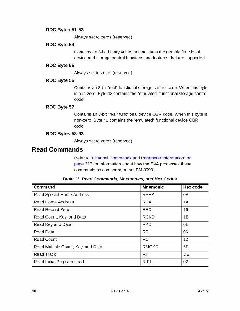
48 Revision N 96219
RDC Bytes 51-53Always set to zeros (reserved)
RDC Byte 54Contains an 8-bit binary value that indicates the generic functional device and storage control functions and features that are supported.
RDC Byte 55Always set to zeros (reserved)
RDC Byte 56Contains an 8-bit “real” functional storage control code. When this byte is non-zero, Byte 42 contains the “emulated” functional storage control code.
RDC Byte 57Contains an 8-bit “real” functional device OBR code. When this byte is non-zero, Byte 41 contains the “emulated” functional device OBR code.
RDC Bytes 58-63Always set to zeros (reserved)
Read CommandsRefer to “Channel Commands and Parameter Information” on page 213 for information about how the SVA processes these commands as compared to the IBM 3990.
Table 13 Read Commands, Mnemonics, and Hex Codes.
Command Mnemonic Hex codeRead Special Home Address RSHA 0A
Read Home Address RHA 1A
Read Record Zero RR0 16
Read Count, Key, and Data RCKD 1E
Read Key and Data RKD 0E
Read Data RD 06
Read Count RC 12
Read Multiple Count, Key, and Data RMCKD 5E
Read Track RT DE
Read Initial Program Load RIPL 02

96219 Revision N 49
Search CommandsRefer to “Channel Commands and Parameter Information” on page 213 for information about how the SVA processes these commands as compared to the IBM 3990.
Write CommandsRefer to “Channel Commands and Parameter Information” on page 213 for information about how the SVA processes these commands as compared to the IBM 3390.
Table 14 Search Commands, Mnemonics, and Hex Codes
Command Mnemonic Hex codeSearch Home Address Equal SHA 39
Search ID Equal SIDE 31
Search ID High SIDH 51
Search ID Equal or High SIDEH 71
Search Key Equal SKE 29
Search Key High SKH 49
Search Key Equal or High SKEH 69
Table 15 Write Commands, Mnemonic, and Hex Codes
Command Mnemonic Hex codeWrite Padding The SVA does not write pad.
Write Special Home Address WSHA 09
Write Home Address WHA 19
Write Record Zero WR0 15
Write Count, Key, and Data WCKD 1D
Write Count, Key, and Data Next Track WCKDNT 9D
Erase ERAS 11
Write Update Key and Data WUKD 8D
Write Key and Data WKD 0D
Write Update Data WUD 85
Write Data WD 05
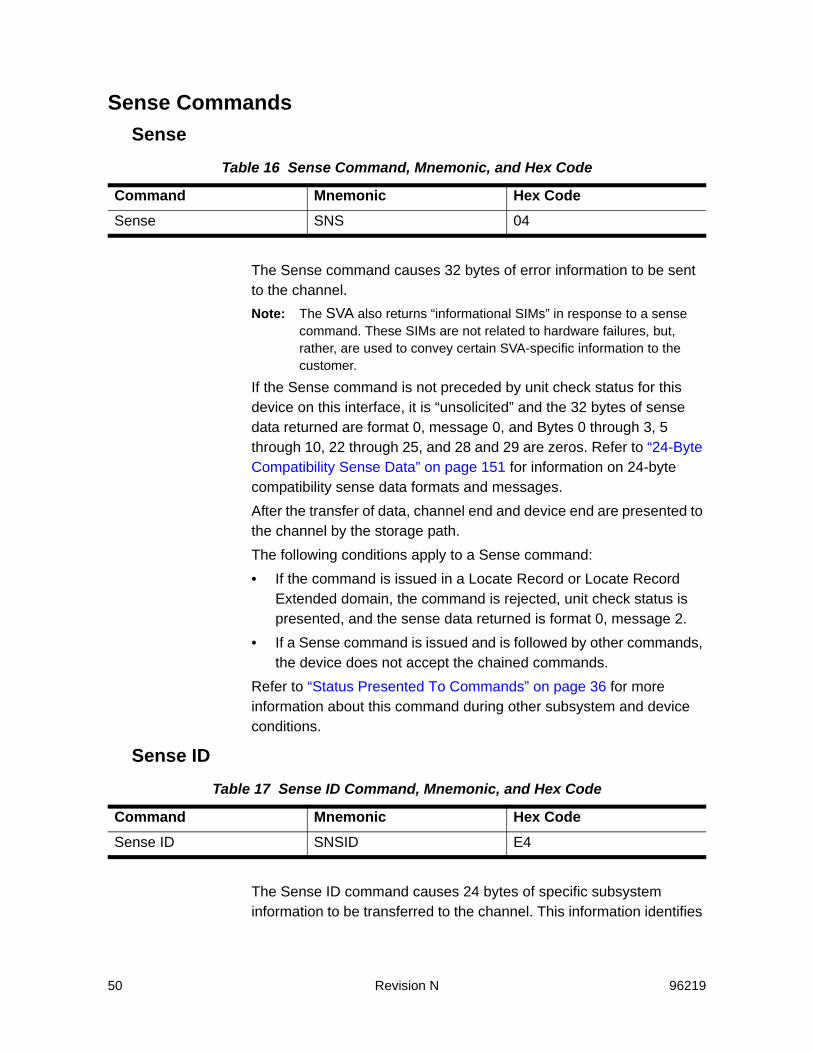
50 Revision N 96219
Sense CommandsSense
The Sense command causes 32 bytes of error information to be sent to the channel.Note: The SVA also returns “informational SIMs” in response to a sense
command. These SIMs are not related to hardware failures, but, rather, are used to convey certain SVA-specific information to the customer.
If the Sense command is not preceded by unit check status for this device on this interface, it is “unsolicited” and the 32 bytes of sense data returned are format 0, message 0, and Bytes 0 through 3, 5 through 10, 22 through 25, and 28 and 29 are zeros. Refer to “24-Byte Compatibility Sense Data” on page 151 for information on 24-byte compatibility sense data formats and messages.After the transfer of data, channel end and device end are presented to the channel by the storage path.The following conditions apply to a Sense command:• If the command is issued in a Locate Record or Locate Record
Extended domain, the command is rejected, unit check status is presented, and the sense data returned is format 0, message 2.
• If a Sense command is issued and is followed by other commands, the device does not accept the chained commands.
Refer to “Status Presented To Commands” on page 36 for more information about this command during other subsystem and device conditions.
Sense ID
The Sense ID command causes 24 bytes of specific subsystem information to be transferred to the channel. This information identifies
Table 16 Sense Command, Mnemonic, and Hex Code
Command Mnemonic Hex CodeSense SNS 04
Table 17 Sense ID Command, Mnemonic, and Hex Code
Command Mnemonic Hex CodeSense ID SNSID E4
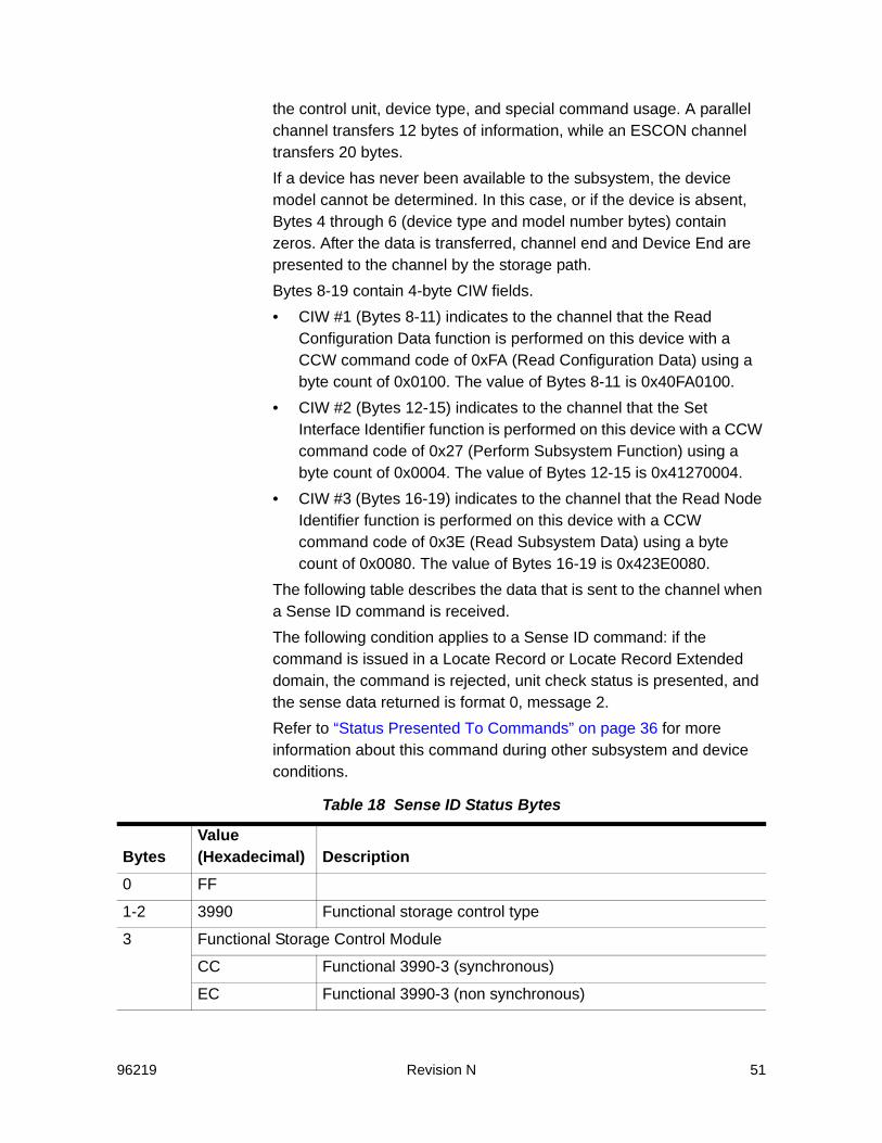
96219 Revision N 51
the control unit, device type, and special command usage. A parallel channel transfers 12 bytes of information, while an ESCON channel transfers 20 bytes. If a device has never been available to the subsystem, the device model cannot be determined. In this case, or if the device is absent, Bytes 4 through 6 (device type and model number bytes) contain zeros. After the data is transferred, channel end and Device End are presented to the channel by the storage path.Bytes 8-19 contain 4-byte CIW fields.• CIW #1 (Bytes 8-11) indicates to the channel that the Read
Configuration Data function is performed on this device with a CCW command code of 0xFA (Read Configuration Data) using a byte count of 0x0100. The value of Bytes 8-11 is 0x40FA0100.
• CIW #2 (Bytes 12-15) indicates to the channel that the Set Interface Identifier function is performed on this device with a CCW command code of 0x27 (Perform Subsystem Function) using a byte count of 0x0004. The value of Bytes 12-15 is 0x41270004.
• CIW #3 (Bytes 16-19) indicates to the channel that the Read Node Identifier function is performed on this device with a CCW command code of 0x3E (Read Subsystem Data) using a byte count of 0x0080. The value of Bytes 16-19 is 0x423E0080.
The following table describes the data that is sent to the channel when a Sense ID command is received.The following condition applies to a Sense ID command: if the command is issued in a Locate Record or Locate Record Extended domain, the command is rejected, unit check status is presented, and the sense data returned is format 0, message 2.Refer to “Status Presented To Commands” on page 36 for more information about this command during other subsystem and device conditions.
Table 18 Sense ID Status Bytes
BytesValue (Hexadecimal) Description
0 FF
1-2 3990 Functional storage control type
3 Functional Storage Control Module
CC Functional 3990-3 (synchronous)
EC Functional 3990-3 (non synchronous)

52 Revision N 96219
4-5 Functional Device Type
3380 Functional 3380
3390 Functional 3390
6 Functional Device Model
Functional 3380
16 3380-J (AJ4/BJ4)
1E 3380K, 3380(6EA)K (AK4/BK4)
Functional 3390 (3390 Mode)
02 3390-1 (A18/B1C)
06 3390-2 (A28/B2C)
0A 3390-3 (A38/B3C)
0C 3390-9 (A98/B9C)
7 00 Not used
8 40 Read Configuration Data command information
9 FA Read Configuration Data command code
10-11 0100 Number of bytes transferred by the Read Configuration Data command
12 41 Set Interface Identifier (SIID) Information
13 27 Perform Subsystem Function command code (command code for SIID order)
14-15 0004 Number of parameters required for SIID order of PSF command
16 42 Read Node Identifier Information
17 3E Read Node Identifier command code
18-19 0080 Number of bytes transferred for a Read Node Identifier request
Table 18 Sense ID Status Bytes (Continued)
BytesValue (Hexadecimal) Description
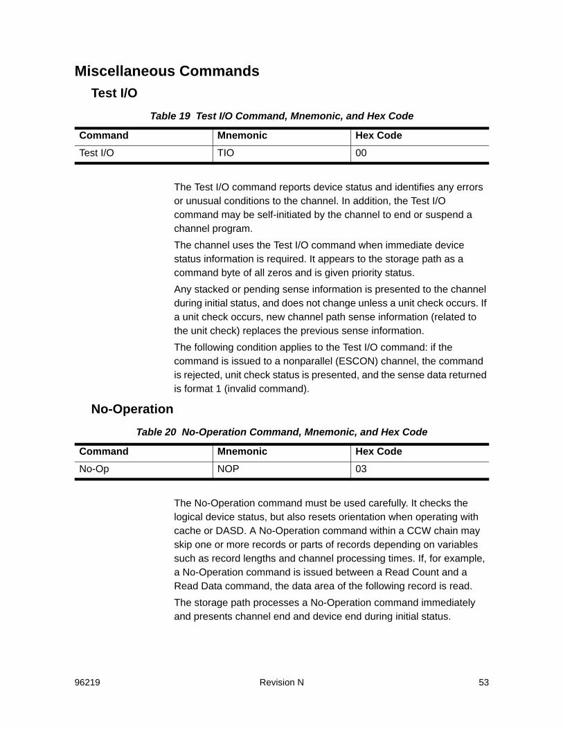
96219 Revision N 53
Miscellaneous CommandsTest I/O
The Test I/O command reports device status and identifies any errors or unusual conditions to the channel. In addition, the Test I/O command may be self-initiated by the channel to end or suspend a channel program. The channel uses the Test I/O command when immediate device status information is required. It appears to the storage path as a command byte of all zeros and is given priority status.Any stacked or pending sense information is presented to the channel during initial status, and does not change unless a unit check occurs. If a unit check occurs, new channel path sense information (related to the unit check) replaces the previous sense information.The following condition applies to the Test I/O command: if the command is issued to a nonparallel (ESCON) channel, the command is rejected, unit check status is presented, and the sense data returned is format 1 (invalid command).
No-Operation
The No-Operation command must be used carefully. It checks the logical device status, but also resets orientation when operating with cache or DASD. A No-Operation command within a CCW chain may skip one or more records or parts of records depending on variables such as record lengths and channel processing times. If, for example, a No-Operation command is issued between a Read Count and a Read Data command, the data area of the following record is read.The storage path processes a No-Operation command immediately and presents channel end and device end during initial status.
Table 19 Test I/O Command, Mnemonic, and Hex Code
Command Mnemonic Hex CodeTest I/O TIO 00
Table 20 No-Operation Command, Mnemonic, and Hex Code
Command Mnemonic Hex CodeNo-Op NOP 03
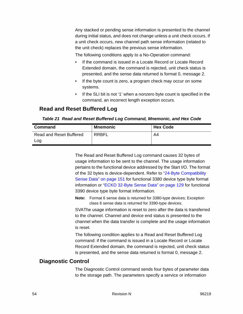
54 Revision N 96219
Any stacked or pending sense information is presented to the channel during initial status, and does not change unless a unit check occurs. If a unit check occurs, new channel path sense information (related to the unit check) replaces the previous sense information.The following conditions apply to a No-Operation command:• If the command is issued in a Locate Record or Locate Record
Extended domain, the command is rejected, unit check status is presented, and the sense data returned is format 0, message 2.
• If the byte count is zero, a program check may occur on some systems.
• If the SLI bit is not ‘1’ when a nonzero byte count is specified in the command, an incorrect length exception occurs.
Read and Reset Buffered Log
The Read and Reset Buffered Log command causes 32 bytes of usage information to be sent to the channel. The usage information pertains to the functional device addressed by the Start I/O. The format of the 32 bytes is device-dependent. Refer to “24-Byte Compatibility Sense Data” on page 151 for functional 3380 device type byte format information or “ECKD 32-Byte Sense Data” on page 129 for functional 3390 device type byte format information.Note: Format 6 sense data is returned for 3380-type devices; Exception
class 6 sense data is returned for 3390-type devices.
SVAThe usage information is reset to zero after the data is transferred to the channel. Channel and device end status is presented to the channel when the data transfer is complete and the usage information is reset.The following condition applies to a Read and Reset Buffered Log command: if the command is issued in a Locate Record or Locate Record Extended domain, the command is rejected, unit check status is presented, and the sense data returned is format 0, message 2.
Diagnostic ControlThe Diagnostic Control command sends four bytes of parameter data to the storage path. The parameters specify a service or information
Table 21 Read and Reset Buffered Log Command, Mnemonic, and Hex Code
Command Mnemonic Hex CodeRead and Reset Buffered Log
RRBFL A4

96219 Revision N 55
request. The mnemonic for this command is DCTL, and the hex code is F3. Refer to the subcommand descriptions for parameter descriptions, and parameter dependent ending status presentation.
The following conditions apply to a Diagnostic Control command:
Table 22 Diagnostic Control Parameters
Byte Parameter Function0 Subcommand Byte
011 Locate Data Checks
022 Inhibit Write
042 Set Guaranteed Path
061 Select Subsystem Data
071 Select Trace
082 Enable Write
091 3380 Track Compatibility Mode Control
0A2 Prepare Remote Support Access Code
0B Diagnostic Initialize Subsystem
0C1 UnFence
0D1 Start Application
0F Access Device in Unknown Condition
102 Media Maintenance Reserve
112 Media Maintenance Release
122 Media Maintenance Query
131 Remote Service Access
1 Subcommand modifier3
2-3 0000 Always set to zeros
Notes:
1. Unit check with format 0, message 4 (invalid parameter)
2. Treated as a No-Operation, so no operation is performed. The subcommand validation is performed as for the 3390.
3. Refer to the subcommand descriptions for more detailed information about the subcommand modifiers.
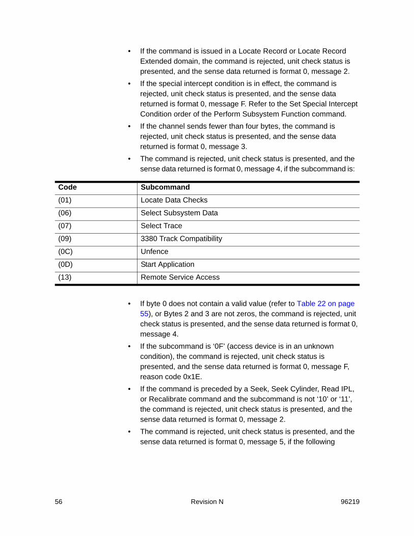
56 Revision N 96219
• If the command is issued in a Locate Record or Locate Record Extended domain, the command is rejected, unit check status is presented, and the sense data returned is format 0, message 2.
• If the special intercept condition is in effect, the command is rejected, unit check status is presented, and the sense data returned is format 0, message F. Refer to the Set Special Intercept Condition order of the Perform Subsystem Function command.
• If the channel sends fewer than four bytes, the command is rejected, unit check status is presented, and the sense data returned is format 0, message 3.
• The command is rejected, unit check status is presented, and the sense data returned is format 0, message 4, if the subcommand is:
• If byte 0 does not contain a valid value (refer to Table 22 on page 55), or Bytes 2 and 3 are not zeros, the command is rejected, unit check status is presented, and the sense data returned is format 0, message 4.
• If the subcommand is ‘0F’ (access device is in an unknown condition), the command is rejected, unit check status is presented, and the sense data returned is format 0, message F, reason code 0x1E.
• If the command is preceded by a Seek, Seek Cylinder, Read IPL, or Recalibrate command and the subcommand is not ‘10’ or ‘11’, the command is rejected, unit check status is presented, and the sense data returned is format 0, message 2.
• The command is rejected, unit check status is presented, and the sense data returned is format 0, message 5, if the following
Code Subcommand(01) Locate Data Checks
(06) Select Subsystem Data
(07) Select Trace
(09) 3380 Track Compatibility
(0C) Unfence
(0D) Start Application
(13) Remote Service Access

96219 Revision N 57
subcommands do not have either a diagnostic authorization or device support authorization. See the table below.
• The command is rejected, unit check status is presented, and the sense data returned is format 0, message 2, if the following subcommands are not the first command in the command chain or are not chained directly from a Suspend Multipath Reconnection command that is the first command in the command chain:
Byte 0 - Subcommand ByteThe subcommand byte parameter specifies a service or information request. The following values are the only valid values for byte 0.Note: In the following descriptions of the subcommands, “Treated as a No-
Operation” means that the subcommand has no effect on subsystem operations.
Locate Data Checks - ‘01’ SubcommandRecords the location of data checks for functional 3380J, 3380K, and 3390 devices. The SVA does not support this command. The command is rejected; channel end, device end, and unit check status are presented; and the sense data returned is format 0, message 4.
Inhibit Write - ‘02’ SubcommandAllows the storage director to reject further write operations through the path specified in the subcommand modifier. The SVA treats this command as a No-Operation. Channel end and device end status is
Code Subcommand(02) Inhibit Write
(04) Set Guaranteed Path
(08) Enable Write
(10) Media Maintenance Reserve
(11) Media Maintenance Release
(12) Media Maintenance Query
Code Subcommand(0A) Prepare Remote Support Access Code
(0B) Diagnostic Initialize Subsystem
(0F) Access Device in Unknown Condition

58 Revision N 96219
presented to the channel. Exception: If the subcommand modifier is not valid, the command is rejected, unit check status is presented, and the sense data returned is format 0, message 4.
Set Guaranteed Path - ‘04’ SubcommandSpecifies the internal path the selected storage director is to use for the remainder of the channel program. The subcommand modifier (byte 1) specifies the storage path for the selected storage director.The SVA treats this command as a No-Operation. Channel end and device end status is presented to the channel. Exception: If the subcommand modifier is not valid, the command is rejected, unit check status is presented, and the sense data returned is format 0, message 4.
Select Subsystem Data - ‘06’ SubcommandSpecifies the type of the subsystem trace or log data that is to be sent to the channel. The SVA does not support this command. The command is rejected; channel end, device end, and unit check status are presented; and the sense data returned is format 0, message 4.
Select Trace - ‘07’ SubcommandSpecifies that a trace is to be sent to the channel. The SVA does not support this command. The command is rejected; channel end, device end, and unit check status are presented; and the sense data returned is format 0, message 4.
Table 23 ‘02’ - Inhibit Write Subcommand Modifiers
Byte 1 Modifier Description80 Inhibit Write operations to all devices through the specified storage director
40 Inhibit Write operations to all devices through the specified storage director for the specified channel path.
20 Inhibit Write operations through the specified DASD controller for the specified channel path.
Table 24 ‘04’ - Set Guaranteed Path Subcommand Modifiers
Byte 1 Modifier Description00 DLSE Mode: selects Path 0 in Cluster 0 or Path 2 in Cluster 1
01 DLSE Mode: selects Path 1 in Cluster 0 or Path 3 in Cluster 1

96219 Revision N 59
Enable Write - ‘08’ SubcommandResets all Inhibit Write subcommands previously set by the storage director receiving the Enable Write command. The SVA treats this command as a No-Operation. Channel end and device end status is presented to the channel. Exception: If the subcommand modifier is not ‘0’, the command is rejected, unit check status is presented, and the sense data returned is format 0, message 4.
3380 Track Compatibility Mode Control - ‘09’ Subcommand Switches a specified function 3390 device between 3390 Mode and 3380 Track Compatibility Mode, and is used on non synchronous channels only. The SVA does not support this command. The command is rejected; channel end, device end, and unit check status are presented; and the sense data returned is format 0, message 4.
Prepare Remote Support Access Code - ‘0A’ SubcommandSVAIndicates a request for a remote support access code. The access code is generated and returned to the channel during processing for the immediately following Diagnostic Sense/Read. The Diagnostic Sense/Read command is placed in retry status until the access code is received from the support processor. The access code authorizes remote maintenance attachment to the support processor. The storage path presents channel end and device end after it accepts the parameters.If byte 1, bits 1 through 7 are not zeros, the command is rejected, unit check status is presented, and the sense data returned is format 0, message 4.
Note: Remote support access codes are not cluster-specific for the SVA. The access code returned is for the subsystem, not for the specified cluster. However, for compatibility with certain host applications, the cluster number specified by the subcommand modifier is imbedded in the access code returned. The most recent access code returned supersedes all preceding access codes. For example, if two requests for access codes are received in rapid succession, the access code
Table 25 ‘0A’ - Prepare Remote Access Code Subcommand
Byte 1 Modifier DescriptionBit 0 ‘0’ - Storage cluster 0
‘1’ - Storage cluster 1
Bits 1-7 Always zeros
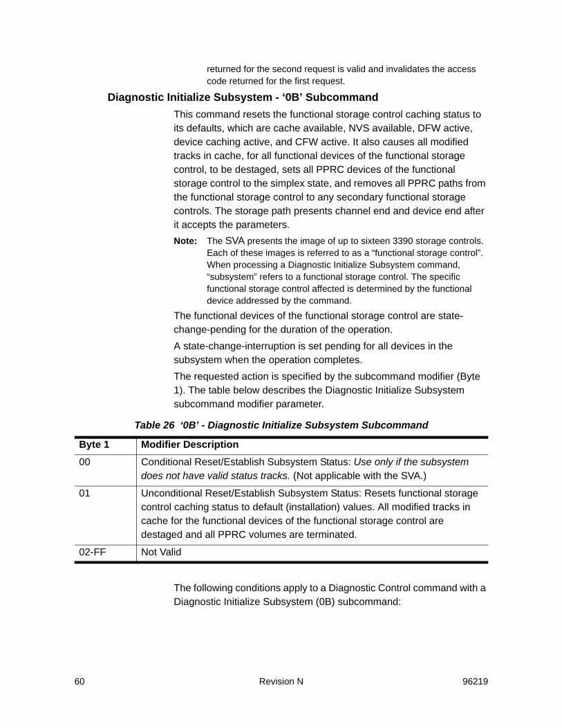
60 Revision N 96219
returned for the second request is valid and invalidates the access code returned for the first request.
Diagnostic Initialize Subsystem - ‘0B’ SubcommandThis command resets the functional storage control caching status to its defaults, which are cache available, NVS available, DFW active, device caching active, and CFW active. It also causes all modified tracks in cache, for all functional devices of the functional storage control, to be destaged, sets all PPRC devices of the functional storage control to the simplex state, and removes all PPRC paths from the functional storage control to any secondary functional storage controls. The storage path presents channel end and device end after it accepts the parameters. Note: The SVA presents the image of up to sixteen 3390 storage controls.
Each of these images is referred to as a “functional storage control”. When processing a Diagnostic Initialize Subsystem command, “subsystem” refers to a functional storage control. The specific functional storage control affected is determined by the functional device addressed by the command.
The functional devices of the functional storage control are state-change-pending for the duration of the operation. A state-change-interruption is set pending for all devices in the subsystem when the operation completes.The requested action is specified by the subcommand modifier (Byte 1). The table below describes the Diagnostic Initialize Subsystem subcommand modifier parameter.
The following conditions apply to a Diagnostic Control command with a Diagnostic Initialize Subsystem (0B) subcommand:
Table 26 ‘0B’ - Diagnostic Initialize Subsystem Subcommand
Byte 1 Modifier Description00 Conditional Reset/Establish Subsystem Status: Use only if the subsystem
does not have valid status tracks. (Not applicable with the SVA.)
01 Unconditional Reset/Establish Subsystem Status: Resets functional storage control caching status to default (installation) values. All modified tracks in cache for the functional devices of the functional storage control are destaged and all PPRC volumes are terminated.
02-FF Not Valid
96219 Revision N 61
• If byte 1 is ‘00’, the command is rejected, unit check status is presented, and the sense data returned is format 0, message F, reason code 0x20.
• If byte 1 is not valid, the command is rejected, unit check status is presented, and the sense data returned is format 0, message 4.
• If all PPRC primary devices in the functional storage control other than the device addressed by the Diagnostic Control command are not offline (i.e. cannot be allocated by the Controller), or if there are any asynchronous channel command operations in progress in the functional control unit, the command is rejected, unit check status is presented, and the sense data returned is format 0, message F, reason code 00.
Unfence - ‘0C’ SubcommandThe Unfence subcommand removes a fence from the storage path or individual devices. The SVA does not support this command. The command is rejected; channel end, device end, and unit check status are presented; and the sense data returned is format 0, message 4.
Start Application - ‘0D’ SubcommandThe Start Application subcommand prepares the subsystem for a Diagnostic Write command. The SVA does not support this command. The command is rejected; channel end, device end, and unit check status are presented; and the sense data returned is format 0, message 4.
Access Device in Unknown Condition - ‘0F’ SubcommandThe Access Device in Unknown Condition subcommand allows status recovery of the selected device when the status is not known because the status track is unreadable or invalid.This condition does not exist with the SVA. The command is rejected, unit check status is presented, and the sense data returned is format 0, message F, reason code 0x1E. (The command is supported, but always unit checked. Functional device status is always available to the SVA.)
Media Maintenance Reserve - ‘10’ SubcommandThe Media Maintenance Reserve subcommand reserves a selected device for media maintenance and is active only during the channel program that issues it. The SVA treats this command as a No-Operation. Channel end and device end status is presented to the channel. Exceptions:
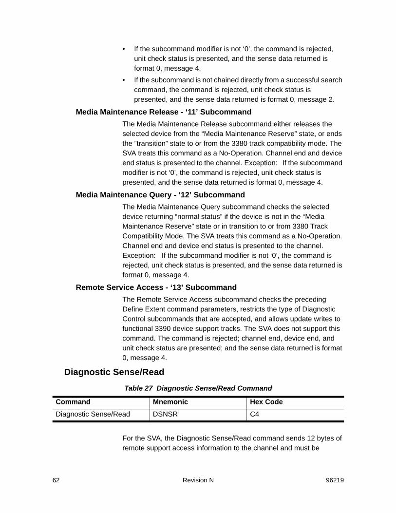
62 Revision N 96219
• If the subcommand modifier is not ‘0’, the command is rejected, unit check status is presented, and the sense data returned is format 0, message 4.
• If the subcommand is not chained directly from a successful search command, the command is rejected, unit check status is presented, and the sense data returned is format 0, message 2.
Media Maintenance Release - ‘11’ SubcommandThe Media Maintenance Release subcommand either releases the selected device from the “Media Maintenance Reserve” state, or ends the ”transition” state to or from the 3380 track compatibility mode. The SVA treats this command as a No-Operation. Channel end and device end status is presented to the channel. Exception: If the subcommand modifier is not ‘0’, the command is rejected, unit check status is presented, and the sense data returned is format 0, message 4.
Media Maintenance Query - ‘12’ SubcommandThe Media Maintenance Query subcommand checks the selected device returning “normal status” if the device is not in the “Media Maintenance Reserve” state or in transition to or from 3380 Track Compatibility Mode. The SVA treats this command as a No-Operation. Channel end and device end status is presented to the channel. Exception: If the subcommand modifier is not ‘0’, the command is rejected, unit check status is presented, and the sense data returned is format 0, message 4.
Remote Service Access - ‘13’ SubcommandThe Remote Service Access subcommand checks the preceding Define Extent command parameters, restricts the type of Diagnostic Control subcommands that are accepted, and allows update writes to functional 3390 device support tracks. The SVA does not support this command. The command is rejected; channel end, device end, and unit check status are presented; and the sense data returned is format 0, message 4.
Diagnostic Sense/Read
For the SVA, the Diagnostic Sense/Read command sends 12 bytes of remote support access information to the channel and must be
Table 27 Diagnostic Sense/Read Command
Command Mnemonic Hex CodeDiagnostic Sense/Read DSNSR C4
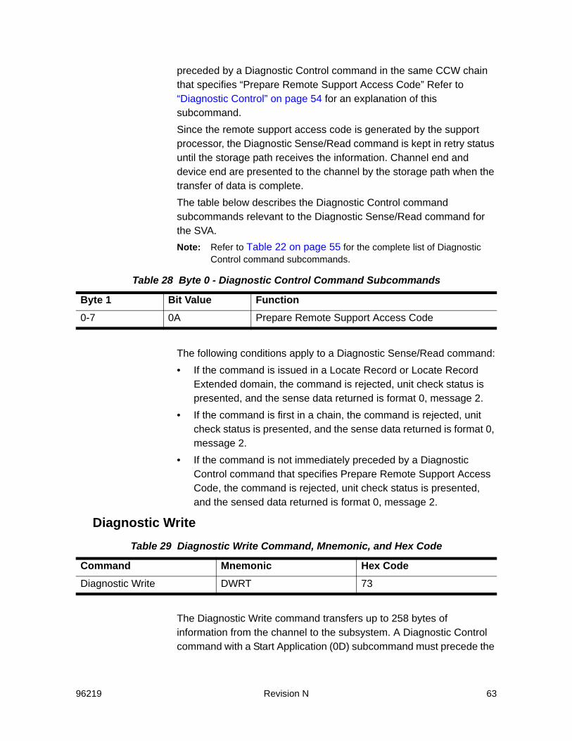
96219 Revision N 63
preceded by a Diagnostic Control command in the same CCW chain that specifies “Prepare Remote Support Access Code” Refer to “Diagnostic Control” on page 54 for an explanation of this subcommand.Since the remote support access code is generated by the support processor, the Diagnostic Sense/Read command is kept in retry status until the storage path receives the information. Channel end and device end are presented to the channel by the storage path when the transfer of data is complete.The table below describes the Diagnostic Control command subcommands relevant to the Diagnostic Sense/Read command for the SVA.Note: Refer to Table 22 on page 55 for the complete list of Diagnostic
Control command subcommands.
The following conditions apply to a Diagnostic Sense/Read command:• If the command is issued in a Locate Record or Locate Record
Extended domain, the command is rejected, unit check status is presented, and the sense data returned is format 0, message 2.
• If the command is first in a chain, the command is rejected, unit check status is presented, and the sense data returned is format 0, message 2.
• If the command is not immediately preceded by a Diagnostic Control command that specifies Prepare Remote Support Access Code, the command is rejected, unit check status is presented, and the sensed data returned is format 0, message 2.
Diagnostic Write
The Diagnostic Write command transfers up to 258 bytes of information from the channel to the subsystem. A Diagnostic Control command with a Start Application (0D) subcommand must precede the
Table 28 Byte 0 - Diagnostic Control Command Subcommands
Byte 1 Bit Value Function0-7 0A Prepare Remote Support Access Code
Table 29 Diagnostic Write Command, Mnemonic, and Hex Code
Command Mnemonic Hex CodeDiagnostic Write DWRT 73

64 Revision N 96219
Diagnostic Write command. However, since a Diagnostic Control command with a Start Application subcommand is invalid for the SVA, the Diagnostic Write command is also invalid for the SVA.If this command is chained to a Diagnostic Control command with a Start Application subcommand, it is not processed; the Diagnostic Control command is rejected.If this command is not chained from a Diagnostic Control command, or if it is issued as the only command in a chain, the command is rejected and the sense data returned is format 0, message 1.
Read Configuration Data
The Read Configuration Data command causes 256 bytes of configuration information to be sent to the channel.The command is organized into four node element descriptors (NEDs) and one node element qualifier (NEQ) that help make it easier to identify and track a physical subsystem and its components as well as its addresses and logical paths. Because of architectural differences between an SVA subsystem and an IBM 3990-3 subsystem, the SVA returns slightly different information in response to a Read Configuration Data command than a 3390-3 does. The following sections, which are separated according to the NEDs and the NEQ, describe the data that the SVA subsystem returns in response to this command. The following condition applies to a Read Configuration Data command: if the command is issued in a Locate Record or Locate Record Extended domain, the command is rejected, unit check status is presented, and the sense data returned is format 0, message 2. Refer to “Status Presented To Commands” on page 36 for more information about this command during other subsystem and device conditions.
Table 30 Read Configuration Data Command, Mnemonic, and Hex Code
Command Mnemonic Hex CodeRead Configuration Data RCD FA

96219 Revision N 65
Bytes 0 through 31 - NED 1Bytes 0 through 31 are described as Node Element Descriptor 1 (NED 1) and contain head-disk assembly (HDA) information..
Table 31 Read Configuration Data Bytes 0 through 31
Byte Hex Value Meaning0 CC Flags
Bit Meaning0-1 Field identifier (always ‘11’ = NED)2 Token indicator (always set to ’0’)3 Serial number valid (always set to ’0’)4 Substitute serial number (always set to ’1’)5 Reconfiguration NED (always set to ’1’)6-7 Reserved (always ’00’)
1 01 NED Type (01 = I/O Device)
2 01 Class (01 = DASD)
3 00 Reserved
4-94040F3F3F8F04040F3F3F9F04040F0F0F0F0
Functional device type in EBCDIC:for 3380-type devicefor 3390-type devicefor undefined device
10-12 Refer to page 72 Functional device model in EBCDIC
13-15 E2E3D2 HDA manufacturer in EBCDIC (E2E3D2 = STK)
16-17 F0F1 or F0F2 HDA manufacturing location in EBCDIC: • F0F1 = Louisville, Colorado• F0F2 = Puerto Rico
18-29 Unit sequence number in EBCDIC: the Controller assembly serial number, which is riveted to the front of the frame in the upper right corner.
30-31 0000-0FFF HDA ID tag - the functional device ID (FDID). Eachfunctional device is considered to be a unique HDA.
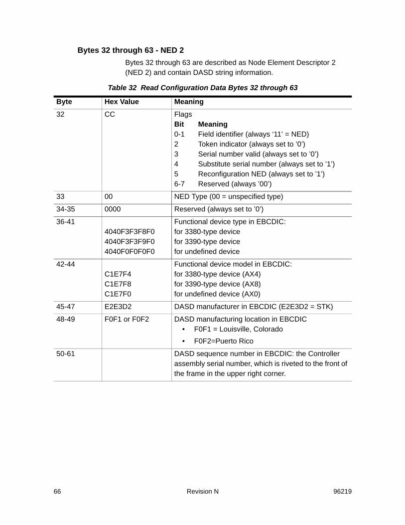
66 Revision N 96219
Bytes 32 through 63 - NED 2Bytes 32 through 63 are described as Node Element Descriptor 2 (NED 2) and contain DASD string information.
Table 32 Read Configuration Data Bytes 32 through 63
Byte Hex Value Meaning32 CC Flags
Bit Meaning0-1 Field identifier (always ‘11’ = NED)2 Token indicator (always set to ’0’)3 Serial number valid (always set to ’0’)4 Substitute serial number (always set to ’1’)5 Reconfiguration NED (always set to ’1’)6-7 Reserved (always ’00’)
33 00 NED Type (00 = unspecified type)
34-35 0000 Reserved (always set to ’0’)
36-414040F3F3F8F04040F3F3F9F04040F0F0F0F0
Functional device type in EBCDIC:for 3380-type devicefor 3390-type devicefor undefined device
42-44C1E7F4C1E7F8C1E7F0
Functional device model in EBCDIC:for 3380-type device (AX4)for 3390-type device (AX8)for undefined device (AX0)
45-47 E2E3D2 DASD manufacturer in EBCDIC (E2E3D2 = STK)
48-49 F0F1 or F0F2 DASD manufacturing location in EBCDIC • F0F1 = Louisville, Colorado• F0F2=Puerto Rico
50-61 DASD sequence number in EBCDIC: the Controller assembly serial number, which is riveted to the front of the frame in the upper right corner.
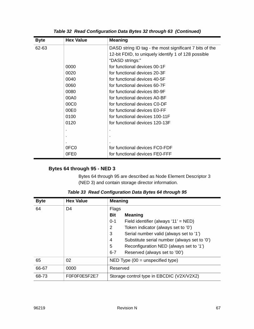
96219 Revision N 67
Bytes 64 through 95 - NED 3Bytes 64 through 95 are described as Node Element Descriptor 3 (NED 3) and contain storage director information.
62-63
0000002000400060008000A000C000E001000120...0FC00FE0
DASD string ID tag - the most significant 7 bits of the 12-bit FDID, to uniquely identify 1 of 128 possible “DASD strings:”for functional devices 00-1Ffor functional devices 20-3Ffor functional devices 40-5Ffor functional devices 60-7Ffor functional devices 80-9Ffor functional devices A0-BFfor functional devices C0-DFfor functional devices E0-FFfor functional devices 100-11Ffor functional devices 120-13F...for functional devices FC0-FDFfor functional devices FE0-FFF
Table 33 Read Configuration Data Bytes 64 through 95
Byte Hex Value Meaning64 D4 Flags
Bit Meaning0-1 Field identifier (always ‘11’ = NED)2 Token indicator (always set to ’0’)3 Serial number valid (always set to ’1’)4 Substitute serial number (always set to ’0’)5 Reconfiguration NED (always set to ’1’)6-7 Reserved (always set to ’00’)
65 02 NED Type (00 = unspecified type)
66-67 0000 Reserved
68-73 F0F0F0E5F2E7 Storage control type in EBCDIC (V2X/V2X2)
Table 32 Read Configuration Data Bytes 32 through 63 (Continued)
Byte Hex Value Meaning
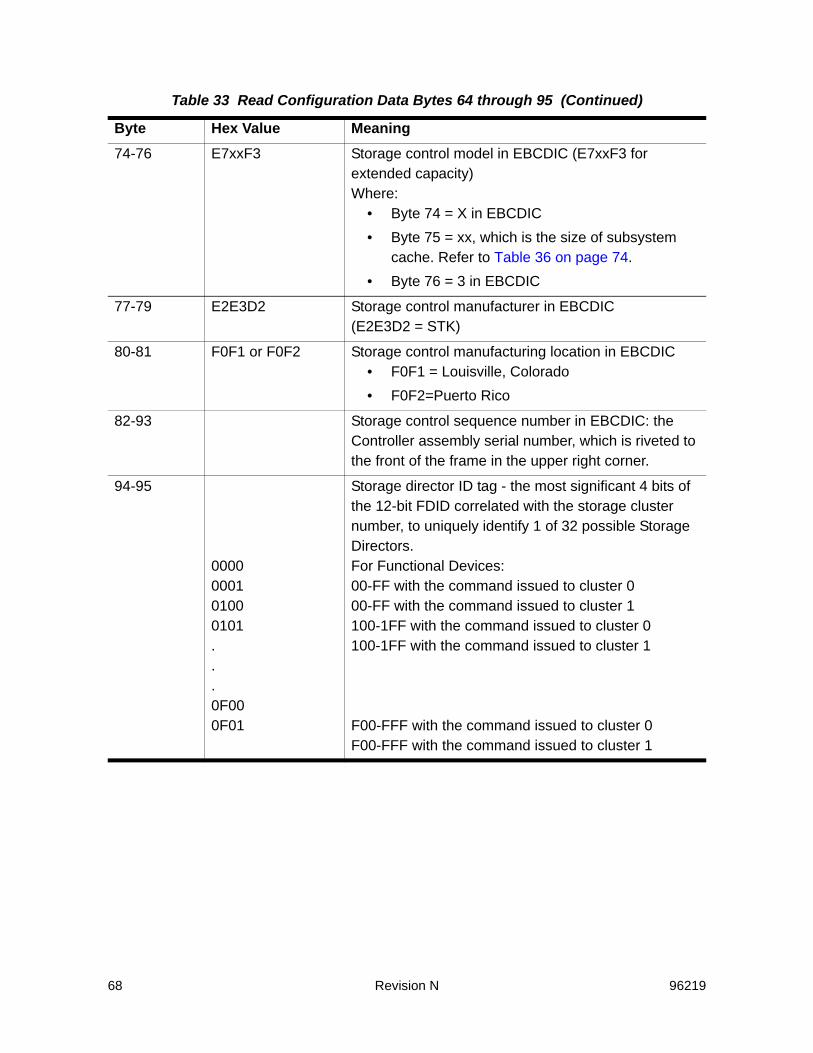
68 Revision N 96219
74-76 E7xxF3 Storage control model in EBCDIC (E7xxF3 for extended capacity)Where:
• Byte 74 = X in EBCDIC• Byte 75 = xx, which is the size of subsystem
cache. Refer to Table 36 on page 74.• Byte 76 = 3 in EBCDIC
77-79 E2E3D2 Storage control manufacturer in EBCDIC (E2E3D2 = STK)
80-81 F0F1 or F0F2 Storage control manufacturing location in EBCDIC • F0F1 = Louisville, Colorado• F0F2=Puerto Rico
82-93 Storage control sequence number in EBCDIC: the Controller assembly serial number, which is riveted to the front of the frame in the upper right corner.
94-95
0000000101000101...0F000F01
Storage director ID tag - the most significant 4 bits of the 12-bit FDID correlated with the storage cluster number, to uniquely identify 1 of 32 possible Storage Directors.For Functional Devices:00-FF with the command issued to cluster 000-FF with the command issued to cluster 1100-1FF with the command issued to cluster 0100-1FF with the command issued to cluster 1
F00-FFF with the command issued to cluster 0F00-FFF with the command issued to cluster 1
Table 33 Read Configuration Data Bytes 64 through 95 (Continued)
Byte Hex Value Meaning

96219 Revision N 69
Bytes 96 through 223 - NED 4Bytes 96 through 223 are described as Node Element Descriptor 4 (NED 4) and contain subsystem information.
Table 34 Read Configuration Data Bytes 96 through 223
Byte Hex Value Meaning96 F0 Flags
Bit Meaning0-1 Field identifier (always ‘11’ = NED)2 Token indicator (always set to ’1’)3 Serial number valid (always set to ’1’)4 Substitute serial number (always set to ’0’)5 Reconfiguration NED (always set to ’0’) 6-7 Reserved (always ’00’)
97 00 NED Type (00 = unspecified type)
98-99 0001 Set to ‘0001’
100-105 F0F0F0E5F2E7 Storage control type in EBCDIC (SVA)
106-108 F0F0F0 Zeros in EBCDIC
109-111 E2E3D2 Storage control manufacturer in EBCDIC (E2E3D2 = STK)
112-113 F0F1 or F0F2 Storage control manufacturing location in EBCDIC • F0F1 = Louisville, Colorado• F0F2=Puerto Rico
114-125 Storage control sequence number in EBCDIC: the Controller assembly serial number, which is riveted to the front of the frame in the upper right corner.
126-127
00000100...0F00
Subsystem ID tag, the most significant 4 bits of the 12-bit FDID, to uniquely identify 1 of 16 possible functional storage controls:for functional devices 00-FF for functional devices 100-1FF...for functional devices F00-FFF
128-223 00 Zeros

70 Revision N 96219
Bytes 224 through 255 - NEQBytes 224 through 255 are described as the Node Element Qualifier (NEQ) and contain path and address information.Note: “Port Pair“ refers to the two ports associated with each Channel
Interface Processor (CIP) on an ICE3 ESCON channel card.
Table 35 Read Configuration Data Bytes 224 through 255
Byte Hex Value Meaning224 80 Flags
Bit Meaning0-1 Field identifier (always ‘10’ = NEQ)2-7 Reserved (always ’000000’)
225 00 Record selector (always ‘00’)
226-227
00xx Interface ID: Where xx =Bit Meaning0 Port Pair ID or Reserved. For ICE3 cards:
•0 = bottom port•1 = top portSee “Note” above.For other ESCON channel cards: reserved (0).
1-2 Card slot location 00-11(0-3) in cluster3 Cluster (0 - 1)4 Reserved (0)5-7 Physical Interface (CIP ID on card )(000 or 001)
•000 = Upper CIP on card•001 = Lower CIP on card
228 FA Device-dependent time-out
229 00 Zeros
230 59 Primary MIH Interval (250 seconds; 4 minutes, 10 seconds)
231 00 Secondary MIH Interval
232-233
0001-FFFF Subsystem ID (SSID) - there are 16 SSIDs per SVA subsystem; one SSID for each functional storage control.

96219 Revision N 71
234C0C1
Paths/storage cluster IDCluster 0 with both storage paths configuredCluster 1 with both storage paths configuredBit Meaning0 Storage path 0 for this cluster is configured in this subsystem
(always set to ’1’)1 Storage path 1 for this cluster is configured in this subsystem
(always set to ’1’)2-6 Zeros7 Storage cluster number (’0’ or ’1’)
235 00-FF Unit address - the address the storage director uses on the channel interface (IDID or Interface Device ID)
236 00-3F Logical device address - the device portion of the unit address in byte 235
237 00-3F Physical device address - the address a storage path uses to address a device (same as byte 236 for the SVA)
238 System Adapter ID (same as byte 227-Interface ID)
239 00 Zeros
240 00-0F Channel Logical Address (CIP number in subsystem)
241 40 Interface Protocol Type (ESCON)
242-255
00 Zeros
Table 35 Read Configuration Data Bytes 224 through 255 (Continued)
Byte Hex Value Meaning

72 Revision N 96219
Functional Device Model (RCD Bytes 10-12)
Functional Device Number 3380-type Device1 3390-type Device1
0 Ay4 Az8
1 Ay4 Az8
2 Ay4 Az8
3 Ay4 Az8
4 By4 Az8
5 By4 Az8
6 By4 Az8
7 By4 Az8
8 By4 BzC
9 By4 BzC
A By4 BzC
B By4 BzC
C By4 BzC
D By4 BzC
E By4 BzC
F By4 BzC
10 By4 BzC
11 By4 BzC
12 By4 BzC
13 By4 BzC
14 By4 BzC
15 By4 BzC
16 By4 BzC
17 By4 BzC
18 By4 BzC
19 By4 BzC
1A By4 BzC
1B By4 BzC
1C By4 BzC
1D By4 BzC

96219 Revision N 73
The following notes apply to the data returned in Bytes 10-12 (Table 31 on page 65) for the Read Configuration Data command (RCD).Note: The SVA emulates four full DASD strings. A full DASD string consists
of eight strings of 32 devices. The values in the table above are for the first string. The values are repeated for the remaining thirty-one strings.
• The first EBCDIC character of the functional device model (byte 10) indicates whether the functional device is considered to be in an A-Unit or a B-Unit.
• The second EBCDIC character of the device model (byte 11) indicates the functional device type. The SVA supports the following functional device types: 3380 J, 3380 K, 3380 K with 6EA cylinders, 3390-1, 3390-2, 3390-3, and 3390-9.
• The third EBCDIC character of the device model (byte 12) indicates the number of functional devices considered to be in the A- or B-Unit.
• The last functional device in an A-Unit is device 3 (for strings of 3380 devices) or device 7 (for strings of 3390 devices). The remainder of the devices in each string are considered to be in B-Units.
1E By4 BzC
1F By4 BzC
Notes:1. y = ’J’ or ’K’ and z = ’1’, ’ 2’, ‘3’, or ’9’
2. For an unknown device type, A00 is returned for Device Model (EBCDIC C1F0F0)
For example:
For device 0x20:
Ay4 if it is a 3380-type deviceAz8 if it is a 3390-type device
For device 0xFF:
By4 if it is a 3380-type deviceBzC if it is a 3390-type device
Functional Device Number 3380-type Device1 3390-type Device1

74 Revision N 96219
• The values in the table above are in EBCDIC. The data returned for the Read Configuration Data command is in hex. For example:
Subsystem Physical Cache Size (RCD Byte 75)
Path Control CommandsDevice Reserve
The Device Reserve command reserves a device to the channel path of the channel sending the command. The command also causes 32 bytes of sense data to be transferred to the channel. After the transfer, channel end and device end are presented to the channel by the storage path.The device reservation lasts until that channel (or any channel in the channel path group) successfully completes a Device Release command to the device, or until all paths on which the device is reserved are reset by a system reset or a subsystem IML.When a Device Reserve command is sent to a device in a contingent allegiance state, normal device status testing performed during initial
Functional Device TypeFunctional Device Model (from previous list)
Functional Device Model (returned to Host)
3380J AJ4 C1D1F4
3380K BK4 C2D2F4
3390-3 B3C C2F3C3
3390-9 A98 C1F9F4
Table 36 Subsystem Physical Cache Size
Byte 75 Hex Value Byte 75 EBCDIC Value Subsystem Cache Size 81 a 8,192 MB (8 GB)
82 b 16,384 MB (16 GB)
83 c 32,768 MB (32 GB)
Table 37 Path Control Command, Mnemonic, and Hex Code
Command Mnemonic Hex CodePath Control RES B4

96219 Revision N 75
selection, is bypassed so that the storage path can present error information from the last unit check.Note: If a device is reserved to a channel path or channel path group, the
existing device reservation is reset for that channel path or channel path group when any channel successfully completes the Unconditional Reserve command. The device then becomes reserved to the channel path or channel path group that sent the Unconditional Reserve command.
The following conditions apply to a Device Reserve command:• If the command is issued in a Locate Record or Locate Record
Extended domain, the command is rejected, unit check status is presented, and the sense data returned is format 0, message 2.
• If the command is preceded in the channel program by any other command, the command is rejected, unit check status is presented, and the sense data returned is format 0, message 2.
Refer to “Status Presented To Commands” on page 36 for more information about this command during other subsystem and device conditions.
Device Release
The Device Release command terminates a device’s reservation. If the command is received for a device in a grouped state, the device reservation is terminated for the channel path group of the channel path sending the command.If the command is received for a device in an ungrouped state, the device reservation is terminated for that channel path.The command also causes 32 bytes of sense data to be transferred to the channel. After the transfer of data, channel end and device end are presented to the channel by the storage path.When a Device Reserve command is sent to a device in a contingent allegiance state, normal device status testing performed during initial selection, is bypassed so that the storage path can present error information from the last unit check.The following conditions apply to a Device Release command:
Table 38 Read Configuration Data Command, Mnemonic, and Hex Code
Command Mnemonic Hex CodeDevice Release REL 94
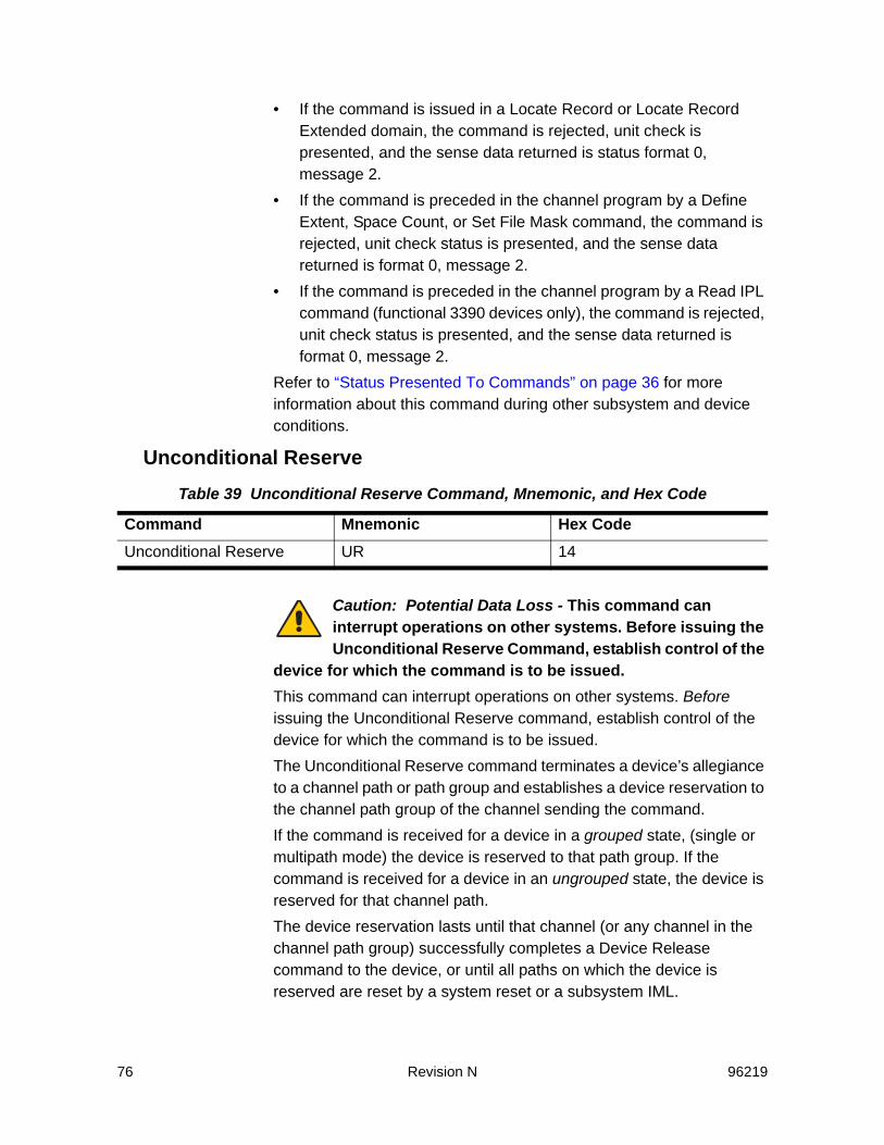
76 Revision N 96219
• If the command is issued in a Locate Record or Locate Record Extended domain, the command is rejected, unit check is presented, and the sense data returned is status format 0, message 2.
• If the command is preceded in the channel program by a Define Extent, Space Count, or Set File Mask command, the command is rejected, unit check status is presented, and the sense data returned is format 0, message 2.
• If the command is preceded in the channel program by a Read IPL command (functional 3390 devices only), the command is rejected, unit check status is presented, and the sense data returned is format 0, message 2.
Refer to “Status Presented To Commands” on page 36 for more information about this command during other subsystem and device conditions.
Unconditional Reserve
Caution: Potential Data Loss - This command can interrupt operations on other systems. Before issuing the Unconditional Reserve Command, establish control of the
device for which the command is to be issued.This command can interrupt operations on other systems. Before issuing the Unconditional Reserve command, establish control of the device for which the command is to be issued.The Unconditional Reserve command terminates a device’s allegiance to a channel path or path group and establishes a device reservation to the channel path group of the channel sending the command.If the command is received for a device in a grouped state, (single or multipath mode) the device is reserved to that path group. If the command is received for a device in an ungrouped state, the device is reserved for that channel path.The device reservation lasts until that channel (or any channel in the channel path group) successfully completes a Device Release command to the device, or until all paths on which the device is reserved are reset by a system reset or a subsystem IML.
Table 39 Unconditional Reserve Command, Mnemonic, and Hex Code
Command Mnemonic Hex CodeUnconditional Reserve UR 14

96219 Revision N 77
This command also causes 32 bytes of sense data to be transferred to the channel. After the transfer of data, channel end is presented by the storage path. device end is presented when the operation is complete.If the device is waiting for an asynchronous operation to complete, the storage path presents channel end to the Unconditional Reserve command, disconnects, and then waits for the asynchronous operation to complete before presenting device end.If a second Unconditional Reserve command, a Reset Allegiance command, or a selective reset is received while waiting for the asynchronous operation to complete, the asynchronous operation is terminated by re initializing cache.Device control must be established prior to issuing the Unconditional Reserve command. Establishing device control is obtained when the host has the device reserved or the host has a CCW chain in progress.When the host sends an Unconditional Reserve command to a device that is not assigned to it, the other system may experience one of the following conditions if the device is:• Reserved. In this case, the reservation is reset and the device
becomes reserved to the channel.• Disconnected between chained commands. In this case, an
interruption is lost.• Active. In this case, the storage path presents a recoverable
equipment check.• Idle and not reserved. In this case, there is no effect.Note: In a functional 3380 Model AA4, devices share internal paths. When
two devices share the same internal path in a string, issuing an Unconditional Reserve command on one controller path may terminate an unrelated operation on the other path.
The following conditions apply to an Unconditional Reserve command:• If the command is issued in a Locate Record or Locate Record
Extended domain, the command is rejected, unit check status is presented, and the sense data returned is format 0, message 2.
• If the command is preceded in the channel program by any other command, the Unconditional Reserve command is rejected, unit check status is presented, and the sense data returned is format 0, message 2.
• If any I/O chain is interrupted by issuing this command, the operation is terminated, unit check status is presented, and the sense data returned is format 0, message F.
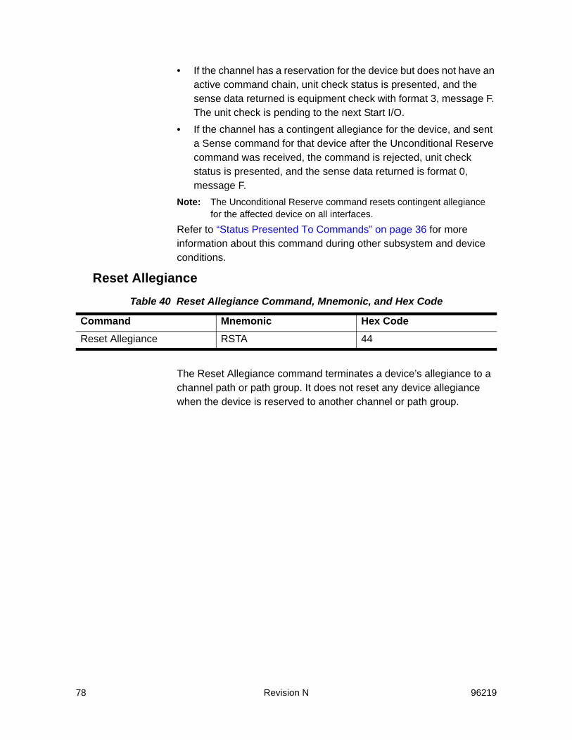
78 Revision N 96219
• If the channel has a reservation for the device but does not have an active command chain, unit check status is presented, and the sense data returned is equipment check with format 3, message F. The unit check is pending to the next Start I/O.
• If the channel has a contingent allegiance for the device, and sent a Sense command for that device after the Unconditional Reserve command was received, the command is rejected, unit check status is presented, and the sense data returned is format 0, message F.
Note: The Unconditional Reserve command resets contingent allegiance for the affected device on all interfaces.
Refer to “Status Presented To Commands” on page 36 for more information about this command during other subsystem and device conditions.
Reset Allegiance
The Reset Allegiance command terminates a device’s allegiance to a channel path or path group. It does not reset any device allegiance when the device is reserved to another channel or path group.
Table 40 Reset Allegiance Command, Mnemonic, and Hex Code
Command Mnemonic Hex CodeReset Allegiance RSTA 44

96219 Revision N 79
This command also causes 32 bytes of data to be transferred to the channel.
Table 41 Data Returned for Reset Allegiance
Byte Definition0 Status
Bits Description0 Device selection successful. When this bit is ’0’ (device selection failed) and
bits 2 and 3 are not ’01’, the storage director tried device selection and failed. The failure that prevented the selection is presented as environmental-data present sense data to the next initial selection to the failing device.
1 Reserved; set to zero
2-3 Reservation StatusValue Definition 00 Device is not reserved 01 Device is reserved to another channel or path group 10 Device is reserved to this channel or path group 11 Reserved
4-5 Allegiance reset for the Addressed Device Value Definition 00 No allegiance was reset for the addressed device 01 Implicit allegiance was reset for the addressed device 10 Contingent allegiance was reset for the addressed device 11 Reserved
6 Contingent allegiance was reset on another device
7 Implicit allegiance was reset on another device
1 Bits0-123-7
DescriptionReserved for the SVAPath Group Identifier supported; set to ’1’Reserved; set to zeros
2-4 Reserved; set to zeros
5-15 Path Group IdentifierIf byte 0, bits 2-3 are set to ’01’ and a Path Group Identifier exists (the channel or path group that the device is reserved to has a valid Path Group Identifier), these bytes contains the Path Group Identifier. Otherwise, these bytes contain zeros.
16-31
Reserved; set to zeros

80 Revision N 96219
After the transfer of data, channel end is presented by the storage path. Device end is presented when the operation is complete.If the device is waiting for an asynchronous operation to complete, the storage path presents channel end to the Reset Allegiance command, disconnects, and then waits for the asynchronous operation to complete before presenting device end.If a second Reset Allegiance command, an Unconditional Reserve command, or a selective reset is received while waiting for the asynchronous operation to complete, the asynchronous operation is terminated by re initializing cache.The following conditions apply to a Reset Allegiance command:• If the command is issued in a Locate Record or Locate Record
Extended domain, the command is rejected, unit check status is presented, and the sense data returned is format 0, message 2.
• If the command is preceded in the channel program by any other command or if it was not chained directly from a Suspend Multipath Reconnection command that was the first CCW in the command chain, the Reset Allegiance command is rejected, unit check status is presented, and the sense data returned is format 0, message 2.
• If a device is either not reserved or reserved to a channel or a channel path group,- If any CCW chain is in progress on this device for this channel
or channel path, it is terminated and status for the CCW chain is reset.
Note: Multi-tagged or un-tagged status for this device is not reset.- If any CCW chain is in progress on this device for another
channel or channel path group, the command is terminated, unit check status is presented, and the sense data returned is format 3, message F.
- If a device is reserved to another channel or channel path group, any other command chained to the Reset Allegiance command, the command is rejected, unit check status is presented, and the sense data returned is format 0F, message 2F.
- If any other channel is currently trying to select the device, that channel may experience either unit check status or a disconnect-in sequence.
- If any sense data pending on this device for another channel or channel path group changes, an equipment check is presented, and the sense data returned is format 3, message F.

96219 Revision N 81
- If device selection fails, any command chained to the Reset Allegiance command is rejected, unit check status is presented, and the sense data returned is format 0, message 2.
Note: In a functional 3380 Model AA4, devices share internal paths. When two devices share the same internal path in a string, issuing an Unconditional Reserve command on one Controller path may terminate an unrelated operation on the other path.
Refer to “Status Presented To Commands” on page 36 for more information about this command during other subsystem and device conditions.
Set Path Group ID
The Set Path Group ID command identifies the system control program controlling a group of channels and defines the paths associated with a processor for the purpose of device reservation and/or dynamic path reconnection.Each host system must have a unique channel path group ID. If the same channel path group ID is assigned to more than one host system, a reserved device would be available to every host system with the same ID.The Set Path Group ID command sends 12 bytes of information to the storage path. The storage path presents channel end and device end after it validates the 12 bytes of information and performs the operation specified in the Control Byte (byte 0). Bytes 1 through 11 contain the channel path group ID for the channel interface. The following conditions apply to a Set Path Group ID command:• If the command is preceded or followed by any other command in
the channel program, the Set Path Group ID command or the command that follows it is rejected, unit check status is presented, and the sense data returned is format 0, message 2.
• If the channel sends fewer than 12 bytes of parameters, the command is rejected, unit check status is presented, and the sense data returned is format 0, message 3.
Table 42 Set Path Group ID Command, Mnemonic, and Hex Code
Command Mnemonic Hex CodeSet Path Group ID SPID AF
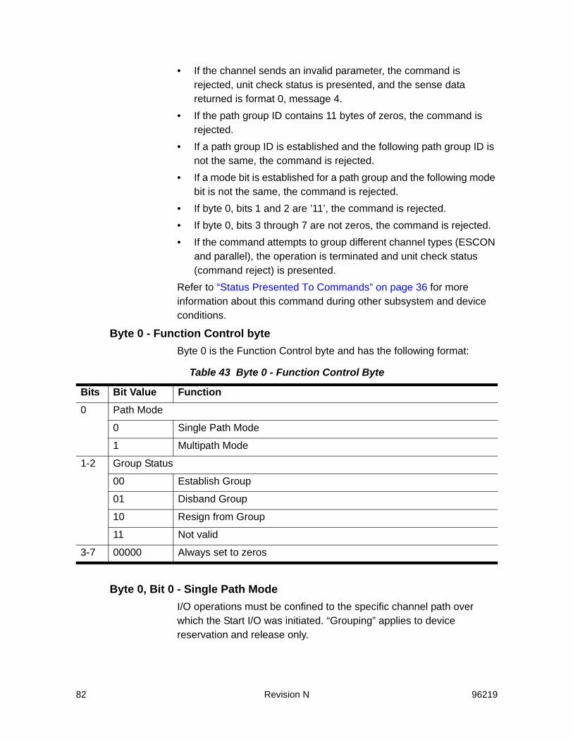
82 Revision N 96219
• If the channel sends an invalid parameter, the command is rejected, unit check status is presented, and the sense data returned is format 0, message 4.
• If the path group ID contains 11 bytes of zeros, the command is rejected.
• If a path group ID is established and the following path group ID is not the same, the command is rejected.
• If a mode bit is established for a path group and the following mode bit is not the same, the command is rejected.
• If byte 0, bits 1 and 2 are ’11’, the command is rejected.• If byte 0, bits 3 through 7 are not zeros, the command is rejected.• If the command attempts to group different channel types (ESCON
and parallel), the operation is terminated and unit check status (command reject) is presented.
Refer to “Status Presented To Commands” on page 36 for more information about this command during other subsystem and device conditions.
Byte 0 - Function Control byteByte 0 is the Function Control byte and has the following format:
Byte 0, Bit 0 - Single Path ModeI/O operations must be confined to the specific channel path over which the Start I/O was initiated. “Grouping” applies to device reservation and release only.
Table 43 Byte 0 - Function Control Byte
Bits Bit Value Function0 Path Mode
0 Single Path Mode
1 Multipath Mode
1-2 Group Status
00 Establish Group
01 Disband Group
10 Resign from Group
11 Not valid
3-7 00000 Always set to zeros

96219 Revision N 83
Byte 0, Bit 1 - Multipath ModeSVAI/O operations initiated on one channel path may be completed on another channel path within the group used by 370-XA.
Byte 0, Bits 1 and 2• If these bits are ’00’, establish group is designated. The storage
director compares the ID (Bytes 1 through 12) with all other IDs received for the same device over other channel paths. A “group” is created for the device consisting of all channel paths with identical IDs.
• If these bits are ’01’, disband group is designated. Each channel path in the original group dedicated to a device is first put into an ungrouped state. If the device was reserved to the channel path group at the time the command was processed, the device remains reserved only to the channel path that issued the command.
• If these bits are ’10’, resign from group is designated. The channel issuing the command is removed from the channel path group dedicated to a device becoming a “stand alone channel”. If the device is reserved to the channel path group at the time the command is processed, the reservation remains with the channel path members left in the group.
• If these bits are ’11’, not valid is designated.
Byte 0, Bits 3 through 7These bits are always set to zeros.
Sense Path Group ID
The Sense Path Group ID command identifies the path groupof the device associated with the channel path sending the command.The Sense Path Group ID command causes 12 bytes of data to be sent from the storage path to the channel. The storage path presents channel end and device end after it sends the 12 bytes of information. Bytes 1 through 11 contain the current path group ID associated with the addressed device for the channel interface. If a Set Path Group ID command has not been issued for any device in the subsystem since
Table 44 Set Path Group ID Command, Mnemonic, and Hex Code
Command Mnemonic Hex CodeSense Path Group ID SNID 34

84 Revision N 96219
the last system reset, Bytes 1 through 11 contain zeros. Byte 0 is the Path State byte and has the format specified in the table below.The following condition applies to a Sense Path Group ID command:• If the command is preceded or followed in the channel program by
any other command or if it was not chained directly from a Suspend Multipath Reconnection command that was the first CCW in the command chain, the Sense Path Group ID command or the command that follows it is rejected, unit check status is presented, and the sense data returned is format 0, message 2.
Refer to See “Status Presented To Commands” on page 36. for more information about this command during other subsystem and device conditions.
Byte 0 - Path State Byte
Byte 0, Bits 0 and 1• If these bits are ’00’, reset is designated. No Set Path Group ID
command has been accepted on this channel since the last system reset or subsystem power-on reset.
• If these bits are ’01’, reserved is designated.
Table 45 Byte 0 - Path State Byte
Bits Bit Value Function0-1 Group Status
00 Reset
01 Reserved
10 Not grouped
11 Grouped
2-3 Reservation Status
00 Not currently reserved
01 Allegiance exists
10 Reserved but not to this channel
11 Reserved to this channel
4 Path Mode
0 Single Path Mode
1 Multipath Mode
5-7 000 Always set to zeros
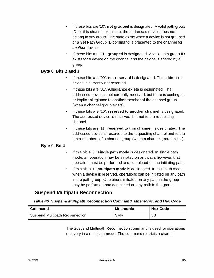
96219 Revision N 85
• If these bits are ’10’, not grouped is designated. A valid path group ID for this channel exists, but the addressed device does not belong to any group. This state exists when a device is not grouped or a Set Path Group ID command is presented to the channel for another device.
• If these bits are ’11’, grouped is designated. A valid path group ID exists for a device on the channel and the device is shared by a group.
Byte 0, Bits 2 and 3• If these bits are ’00’, not reserved is designated. The addressed
device is currently not reserved.• If these bits are ’01’, Allegiance exists is designated. The
addressed device is not currently reserved, but there is contingent or implicit allegiance to another member of the channel group (when a channel group exists).
• If these bits are ’10’, reserved to another channel is designated. The addressed device is reserved, but not to the requesting channel.
• If these bits are ’11’, reserved to this channel, is designated. The addressed device is reserved to the requesting channel and to the other members of a channel group (when a channel group exists).
Byte 0, Bit 4• If this bit is ’0’, single path mode is designated. In single path
mode, an operation may be initiated on any path; however, that operation must be performed and completed on the initiating path.
• If this bit is ’1’, multipath mode is designated. In multipath mode, when a device is reserved, operations can be initiated on any path in the path group. Operations initiated on any path in the group may be performed and completed on any path in the group.
Suspend Multipath Reconnection
The Suspend Multipath Reconnection command is used for operations recovery in a multipath mode. The command restricts a channel
Table 46 Suspend Multipath Reconnection Command, Mnemonic, and Hex Code
Command Mnemonic Hex CodeSuspend Multipath Reconnection SMR 5B
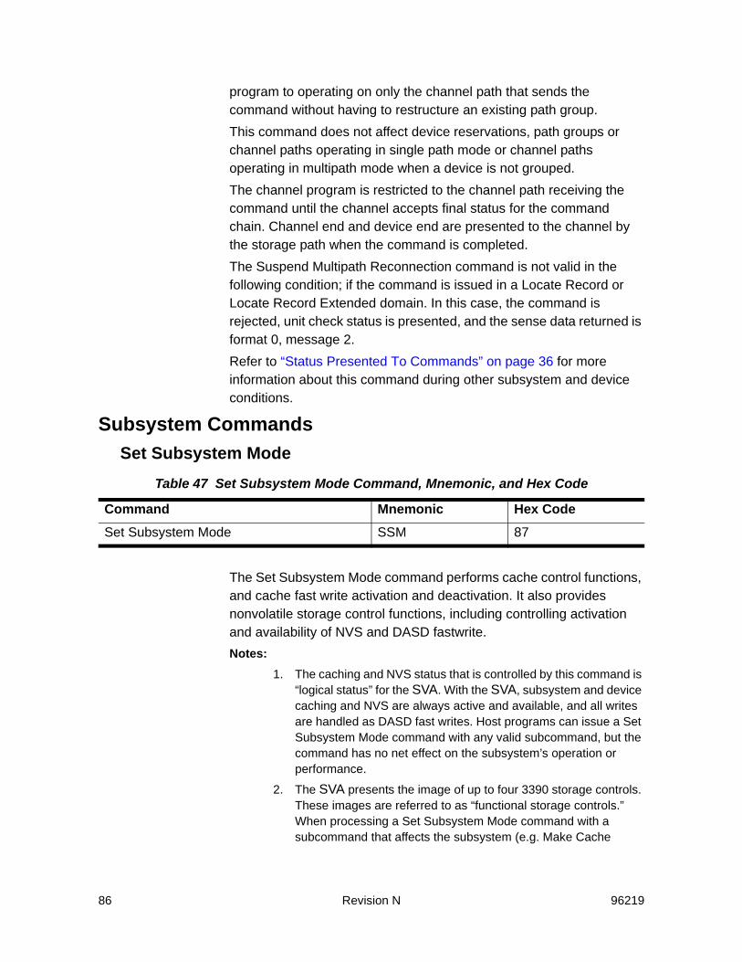
86 Revision N 96219
program to operating on only the channel path that sends the command without having to restructure an existing path group.This command does not affect device reservations, path groups or channel paths operating in single path mode or channel paths operating in multipath mode when a device is not grouped.The channel program is restricted to the channel path receiving the command until the channel accepts final status for the command chain. Channel end and device end are presented to the channel by the storage path when the command is completed.The Suspend Multipath Reconnection command is not valid in the following condition; if the command is issued in a Locate Record or Locate Record Extended domain. In this case, the command is rejected, unit check status is presented, and the sense data returned is format 0, message 2.Refer to “Status Presented To Commands” on page 36 for more information about this command during other subsystem and device conditions.
Subsystem CommandsSet Subsystem Mode
The Set Subsystem Mode command performs cache control functions, and cache fast write activation and deactivation. It also provides nonvolatile storage control functions, including controlling activation and availability of NVS and DASD fastwrite. Notes:
1. The caching and NVS status that is controlled by this command is “logical status” for the SVA. With the SVA, subsystem and device caching and NVS are always active and available, and all writes are handled as DASD fast writes. Host programs can issue a Set Subsystem Mode command with any valid subcommand, but the command has no net effect on the subsystem’s operation or performance.
2. The SVA presents the image of up to four 3390 storage controls. These images are referred to as “functional storage controls.” When processing a Set Subsystem Mode command with a subcommand that affects the subsystem (e.g. Make Cache
Table 47 Set Subsystem Mode Command, Mnemonic, and Hex Code
Command Mnemonic Hex CodeSet Subsystem Mode SSM 87
96219 Revision N 87
Available to Subsystem), “subsystem” refers to a functional storage control. The functional storage control affected is determined by the functional device addressed by the command.
3. A Set Subsystem Mode command causes the logical status of caching or NVS to be updated in Controller memory, on the physical drives, and on the support processor hard drives. For SSM subcommands that specify an “activate” or “make available” operation, the operation is complete when the status has been updated in these three locations.
4. A Set Subsystem Mode command that specifies a “deactivate” or “make unavailable” operation causes modified data (cache fast write and DASD fast write data) to be queued for destage from volatile cache. When the destage is complete, the copies of the data that was destaged are deleted from NVS. The operation is complete when the data has been queued for destage and the status has been updated in the 3 locations specified above. The actual destage of modified data and deletion of copies of the modified data in NVS may occur after the Controller responds that the operation is complete.
Two parameter bytes that are received with the Set Subsystem Mode command determine the scope of the command. For a description of the operation of this command when other subsystem and device status conditions occur, refer to “Status Presented To Commands” on page 36.The following conditions apply to a Set Subsystem Mode command:• If the command is issued in a Locate Record or Locate Record
Extended domain, the command is rejected, unit check status is presented, and the sense data returned is format 0, message 2.
• If the command is not in a valid chain, the command is rejected, unit check status is presented, and the sense data returned is format 0, message 2.
To be valid, the command must be either the first command in a chain, or must immediately follow a Suspend Multipath Reconnection command that is the first command in a chain.
• If the Message Required bit (byte 0, bit 7) is ’0’, the Set Subsystem Mode command must be the last command in a chain. Any command chained from this command is rejected, unit check status is presented, and the sense data returned is format 0, message 2.
• If the Message Required bit is ’1’, a Read Message ID command can be chained from this command. If the Message Required bit is ’1’ and the Set Subsystem Mode Command is not followed by
88 Revision N 96219
Read Message ID, the operation is performed but no ending notification occurs.
• If the Message Required bit is ’1’ and a command other than Read Message ID is chained from the Set Subsystem Mode command, that command is rejected, unit check status is presented, and the sense data returned is format 0, message 2.
• If more than two parameter bytes are received, only the first two bytes are accepted by the storage path. If fewer than two bytes are received, the command is rejected, unit check status is presented, and the sense data returned is format 0, message 3.
• If the parameter bytes are invalid, the command is rejected, unit check status is presented, and the sense data returned is format 0, message 4. Valid parameters are:- An operation can be specified for only one control field: cache
control, cache fast write control, or nonvolatile storage control. Other control fields must contain all zeros.
- Byte 0, bit 6 and byte 1, bits 11 through 15 must be all zeros.- Message Required (byte 0, bit 7) is valid only with operations
that are asynchronous.
Ending StatusAll conditions set by the Set Subsystem Mode command remain intact after a subsystem Initial Microprogram Load (IML).For a description of the completion status of operations that require a long time period to complete, refer to “Asynchronous Operations” on page 18.The storage path presents the following status in response to the Set Subsystem Mode command:• If a buffer is not available in memory to process the requested
asynchronous operation, the command is rejected, unit check status is presented, and the sense data returned is format 0, message F.
• If the condition requested by the command already exists, no operation is performed. Successful completion is shown in the ending status (channel end and device end) or in the message.
• The storage path presents device end with channel end when all operation codes are ’000’, or when two operation codes are ’000’ and the third is a reserved value.

96219 Revision N 89
• The storage path presents channel end if it receives valid parameter bytes that specify a single operation and all conditions for processing the command are met.
• For synchronous operations, device end is presented when the requested operation is complete.
• For asynchronous operations, device end is presented when the requested operation is started.
• For asynchronous operations, device end is presented with channel end when the requested operation is already in progress because another Set Subsystem Mode command specified the same operation.
SSM Byte 0 - Cache Control, CFW Control, and Message Required BitByte 0 of the command parameters can specify a cache or cache fast write operation, but only if no NVS operation is specified in byte 1 of the command parameters. Byte 0, bit 7 specifies whether or not an attention message is required for an asynchronous operation specified in byte 0 or 1, when the operation is completed.Byte 0 has the following format:
Table 48 Byte 0 - Cache Control and Message Required Bit
BitsBit Value Function
0-2 Cache Control
000 No Cache Operation
001 Activate caching for addressed device
010 Deactivate caching for addressed device1
011 Make cache available to subsystem1, 2
100 Make cache unavailable to subsystem1, 2
101 Force cache unavailable to subsystem1
110 Reserved
111 Reserved
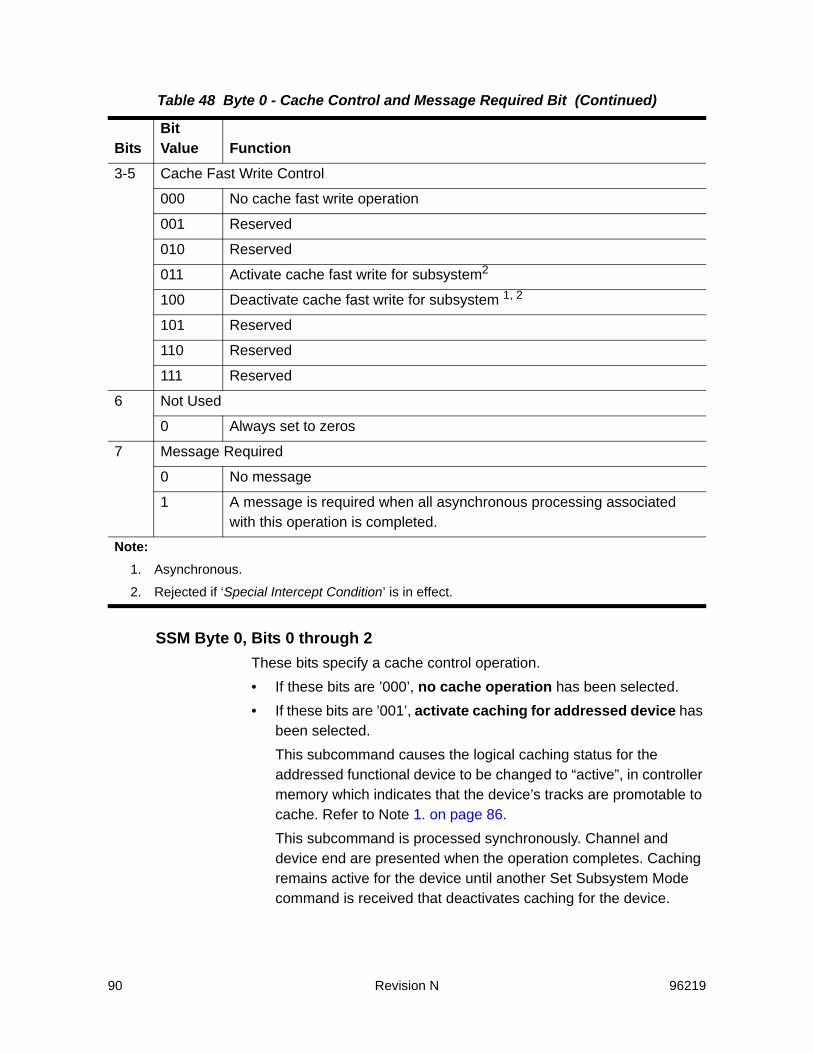
90 Revision N 96219
SSM Byte 0, Bits 0 through 2These bits specify a cache control operation.• If these bits are ’000’, no cache operation has been selected.• If these bits are ’001’, activate caching for addressed device has
been selected.This subcommand causes the logical caching status for the addressed functional device to be changed to “active”, in controller memory which indicates that the device’s tracks are promotable to cache. Refer to Note 1. on page 86.This subcommand is processed synchronously. Channel and device end are presented when the operation completes. Caching remains active for the device until another Set Subsystem Mode command is received that deactivates caching for the device.
3-5 Cache Fast Write Control
000 No cache fast write operation
001 Reserved
010 Reserved
011 Activate cache fast write for subsystem2
100 Deactivate cache fast write for subsystem 1, 2
101 Reserved
110 Reserved
111 Reserved
6 Not Used
0 Always set to zeros
7 Message Required
0 No message
1 A message is required when all asynchronous processing associated with this operation is completed.
Note:1. Asynchronous.
2. Rejected if ‘Special Intercept Condition’ is in effect.
Table 48 Byte 0 - Cache Control and Message Required Bit (Continued)
BitsBit Value Function
96219 Revision N 91
Caching can be activated for a device whether or not caching is logically available for the subsystem.The following conditions apply to this subcommand:- If cache is pending-off for the subsystem, the subcommand is
rejected, unit check is presented, and the sense data returned is format 0 message F.
- If caching is already activated for the device, no further processing occurs and device end is presented with channel end.
• If these bits are ’010’, deactivate caching for addressed device has been selected.
This subcommand causes the logical caching status for the addressed functional device to be changed to “deactivated”, which indicates that the device’s tracks must bypass cache. Refer to Note 1. on page 86.This subcommand also causes all of the modified tracks for the device to be queued for destage. This subcommand is processed asynchronously. Refer to “Asynchronous Operations” on page 18.Caching remains inactive for the device until another Set Subsystem Mode command is received that activates caching for the device or until a Diagnostic Control command with a Diagnostic Initialize Subsystem subcommand is received that affects the device.The addressed device is put in a state-change-pending state for the duration of the operation. Upon completion of the operation, a state-change-interrupt (85 status) is presented to each channel path group with which the addressed device is grouped, and to each ungrouped channel that has access to the device.This condition applies to this subcommand; if caching is already deactivated for the device, no further processing occurs, and device end is presented with channel end.• If these bits are ’011’, make cache available to subsystem has
been selected.This subcommand causes the logical caching status for the functional storage control to be changed to “available”, which indicates that the tracks of the 64 functional devices that comprise the functional storage control are promotable to cache. Refer to Note 1. on page 86.This subcommand is processed asynchronously. Refer to “Asynchronous Operations” on page 18.

92 Revision N 96219
Caching remains available for the subsystem until another Set Subsystem Mode command is received that makes caching unavailable for the subsystem.The following conditions apply to this subcommand:- If cache is pending-off for the subsystem, the subcommand is
rejected, unit check status is presented, and the sense data returned is format 0 message F.
- If caching is already available for the subsystem, no further processing occurs and device end is presented with channel end.
• If these bits are ’100’, make cache unavailable to subsystem has been selected.This subcommand is treated as a no-operationcauses the logical cache fast write status for the functional storage control to be changed to “unavailable”, which indicates that access to the tracks of the 64 functional devices that comprise the functional storage control must bypass cache. Refer to Note 1. on page 86.This subcommand is processed asynchronously. Refer to “Asynchronous Operations” on page 18. This subcommand also causes all of the modified tracks for the functional storage control’s 64 functional devices to be queued for destage. Caching remains unavailable for the subsystem until another Set Subsystem Mode command is received that makes cache available for the subsystem or until a Diagnostic Control command with a Diagnostic Initialize Subsystem subcommand is received for this functional storage control. The following conditions apply to this subcommand: - If the Special Intercept Condition is in effect, this subcommand
is rejected. - If cache is pending-on for the subsystem, the subcommand is
rejected, unit check status is presented, and the sense data returned is format 0, message F.
- If cache is already unavailable for the subsystem, no further processing occurs and device end is presented with channel end.
• If these bits are ’101’, force cache unavailable to subsystem has been selected. The SVA does not support this subcommand; it is
96219 Revision N 93
rejected, unit check status is presented, and the sense data returned is format 0 message 4.
SSM Byte 0, Bits 3 through 5These bits specify a cache fast write control operation.• If these bits are ’000’, no cache fast write operation has been
selected.• If these bits are ’011’, activate cache fast write for subsystem
has been selected.This subcommand causes the logical cache fast write status for the functional storage control to be changed to “active”, which indicates that cache fast write operations for the 64 functional devices that comprise the functional storage control are allowed. Refer to Note 1. on page 86.This subcommand is processed synchronously. Device end is presented when the operation completes.Cache fast write remains active for the subsystem until another Set Subsystem Mode command is received that deactivates cache fast write for the subsystem.The following conditions apply to this subcommand:- If the Special Intercept Condition is in effect, this subcommand
is rejected. - If cache fast write is pending-off for the subsystem, the
subcommand is rejected, unit check status is presented, and the sense data returned is format 0, message F.
- If caching fast write is already active for the subsystem, no further processing occurs, and device end is presented with channel end.
• If these bits are ‘100’, deactivate cache fast write for subsystem has been selected. This subcommand causes the logical cache fast write status for the functional storage control to be changed to “deactivated”, which indicates that cache fast write operations for the 64 functional devices that comprise the functional storage control are disallowed. Refer to Note 1. on page 86. This subcommand also causes all of the modified tracks for the functional storage control’s 64 functional devices to be queued for destage. This subcommand is processed asynchronously. Refer to “Asynchronous Operations” on page 18. Cache fast write remains deactivated for the subsystem until another Set Subsystem Mode
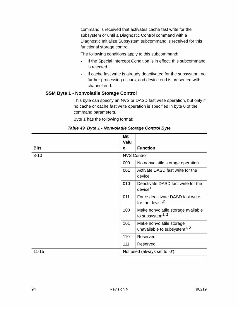
94 Revision N 96219
command is received that activates cache fast write for the subsystem or until a Diagnostic Control command with a Diagnostic Initialize Subsystem subcommand is received for this functional storage control.The following conditions apply to this subcommand:- If the Special Intercept Condition is in effect, this subcommand
is rejected. - If cache fast write is already deactivated for the subsystem, no
further processing occurs, and device end is presented with channel end.
SSM Byte 1 - Nonvolatile Storage ControlThis byte can specify an NVS or DASD fast write operation, but only if no cache or cache fast write operation is specified in byte 0 of the command parameters.Byte 1 has the following format:
Table 49 Byte 1 - Nonvolatile Storage Control Byte
Bits
Bit Value Function
8-10 NVS Control
000 No nonvolatile storage operation
001 Activate DASD fast write for the device
010 Deactivate DASD fast write for the device1
011 Force deactivate DASD fast write for the device2
100 Make nonvolatile storage available to subsystem1, 2
101 Make nonvolatile storage unavailable to subsystem1, 2
110 Reserved
111 Reserved
11-15 Not used (always set to ‘0’)
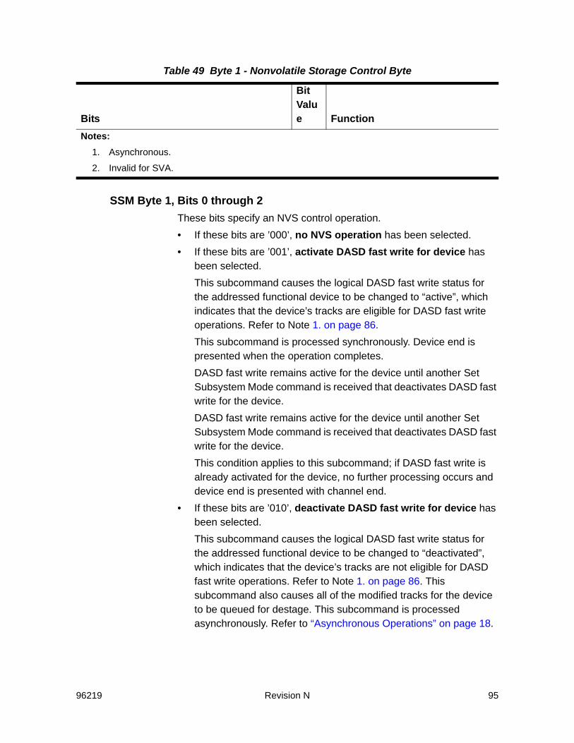
96219 Revision N 95
SSM Byte 1, Bits 0 through 2These bits specify an NVS control operation.• If these bits are ’000’, no NVS operation has been selected.• If these bits are ’001’, activate DASD fast write for device has
been selected.This subcommand causes the logical DASD fast write status for the addressed functional device to be changed to “active”, which indicates that the device’s tracks are eligible for DASD fast write operations. Refer to Note 1. on page 86.This subcommand is processed synchronously. Device end is presented when the operation completes.DASD fast write remains active for the device until another Set Subsystem Mode command is received that deactivates DASD fast write for the device.DASD fast write remains active for the device until another Set Subsystem Mode command is received that deactivates DASD fast write for the device.This condition applies to this subcommand; if DASD fast write is already activated for the device, no further processing occurs and device end is presented with channel end.
• If these bits are ’010’, deactivate DASD fast write for device has been selected.This subcommand causes the logical DASD fast write status for the addressed functional device to be changed to “deactivated”, which indicates that the device’s tracks are not eligible for DASD fast write operations. Refer to Note 1. on page 86. This subcommand also causes all of the modified tracks for the device to be queued for destage. This subcommand is processed asynchronously. Refer to “Asynchronous Operations” on page 18.
Notes:1. Asynchronous.
2. Invalid for SVA.
Table 49 Byte 1 - Nonvolatile Storage Control Byte
Bits
Bit Value Function
96 Revision N 96219
DASD fast write remains inactive for the device until another Set Subsystem Mode command is received that activates DASD fast write for the device or until a Diagnostic Control command with a Diagnostic Initialize Subsystem subcommand is received that affects the device.The addressed device is put in a state-change-pending state for the duration of the operation. Upon completion of the operation, a state-change-interrupt (85 status) is presented to each channel path group that the addressed device is grouped with, and to each ungrouped channel that has access to the device.This condition applies to this subcommand; if DASD fast write is already deactivated for the device, no further processing occurs and device end is presented with channel end.
• If these bits are ’011’, force deactivate DASD fast write for device has been selected. The SVA does not support this subcommand; it is rejected, unit check status is presented, and the sense data returned is format 0, message 4.
• If these bits are ’100’, make NVS available to subsystem has been selected.This subcommand causes the logical NVS status for the functional storage control to be changed to “available”, which indicates that NVS is available for DASD fast write operations for the 64 functional devices that comprise the functional storage control. Refer to Note 1. on page 86. This subcommand is processed asynchronously. Refer to “Asynchronous Operations” on page 18.NVS remains available for the subsystem until another Set Subsystem Mode command is received that makes NVS unavailable for the subsystem.The following conditions apply to this subcommand:- If the Special Intercept Condition is in effect, this subcommand
is rejected. - If NVS is pending-off for the subsystem, the subcommand is
rejected, unit check status is presented, and the sense data returned is format 0, message F.
- If NVS is already available for the subsystem, no further processing occurs and device end is presented with channel end.
• If these bits are ’101’, make NVS unavailable to subsystem has been selected.
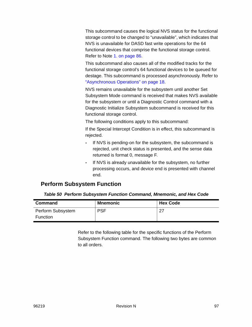
96219 Revision N 97
This subcommand causes the logical NVS status for the functional storage control to be changed to “unavailable”, which indicates that NVS is unavailable for DASD fast write operations for the 64 functional devices that comprise the functional storage control. Refer to Note 1. on page 86.This subcommand also causes all of the modified tracks for the functional storage control’s 64 functional devices to be queued for destage. This subcommand is processed asynchronously. Refer to “Asynchronous Operations” on page 18.NVS remains unavailable for the subsystem until another Set Subsystem Mode command is received that makes NVS available for the subsystem or until a Diagnostic Control command with a Diagnostic Initialize Subsystem subcommand is received for this functional storage control.The following conditions apply to this subcommand:If the Special Intercept Condition is in effect, this subcommand is rejected. - If NVS is pending-on for the subsystem, the subcommand is
rejected, unit check status is presented, and the sense data returned is format 0, message F.
- If NVS is already unavailable for the subsystem, no further processing occurs, and device end is presented with channel end.
Perform Subsystem Function
Refer to the following table for the specific functions of the Perform Subsystem Function command. The following two bytes are common to all orders.
Table 50 Perform Subsystem Function Command, Mnemonic, and Hex Code
Command Mnemonic Hex CodePerform Subsystem Function
PSF 27
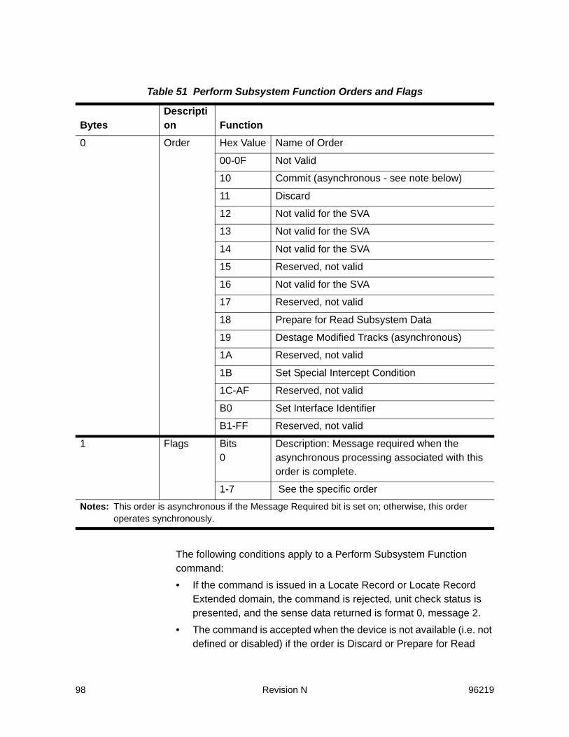
98 Revision N 96219
The following conditions apply to a Perform Subsystem Function command:• If the command is issued in a Locate Record or Locate Record
Extended domain, the command is rejected, unit check status is presented, and the sense data returned is format 0, message 2.
• The command is accepted when the device is not available (i.e. not defined or disabled) if the order is Discard or Prepare for Read
Table 51 Perform Subsystem Function Orders and Flags
BytesDescription Function
0 Order Hex Value Name of Order
00-0F Not Valid
10 Commit (asynchronous - see note below)
11 Discard
12 Not valid for the SVA
13 Not valid for the SVA
14 Not valid for the SVA
15 Reserved, not valid
16 Not valid for the SVA
17 Reserved, not valid
18 Prepare for Read Subsystem Data
19 Destage Modified Tracks (asynchronous)
1A Reserved, not valid
1B Set Special Intercept Condition
1C-AF Reserved, not valid
B0 Set Interface Identifier
B1-FF Reserved, not valid
1 Flags Bits0
Description: Message required when the asynchronous processing associated with this order is complete.
1-7 See the specific order
Notes: This order is asynchronous if the Message Required bit is set on; otherwise, this order operates synchronously.

96219 Revision N 99
Subsystem Data. However, if the command is accepted with either of these conditions and the order in byte 0 is not X’11’ or X’18’, the command is rejected, unit check status is presented, and the sense data returned includes Intervention Required, and is format 1, message 0 for 3380-type devices, or exception class E for 3390-type devices.
• The Perform Subsystem Function command with a Destage Modified Tracks order must be one of the following:- The first command in the chain - Chained directly from a Suspend Multipath Reconnection
command that is first in the chain - Immediately preceded by a Define Extent command with the
authorization set to diagnostic or device support authorization.If these requirements are not met, the command is rejected, unit check status is presented, and the sense data returned is format 0, message 2.• The orders have different parameter lengths. If the channel sends
more bytes than the order requires, the storage path accepts only the number of bytes required by the order. If the channel sends fewer bytes than the order requires, the command is rejected, unit check status is presented, and the sense data returned is format 0, message 3. (Refer to the description of the specific order for any additional requirements.)
• If a buffer is not available in memory to process the requested asynchronous operation, the command is rejected, unit check status is presented, and the sense data returned is format 0, message F.Refer to the specific order for additional information, and for those orders that are specified as “asynchronous”, refer to “Asynchronous Operations” on page 18.
Commit X‘10’This order causes the modified data on the functional tracks specified within the extent range for the addressed device to be queued for destage. The data on the specified tracks is between the specified beginning andending extents.
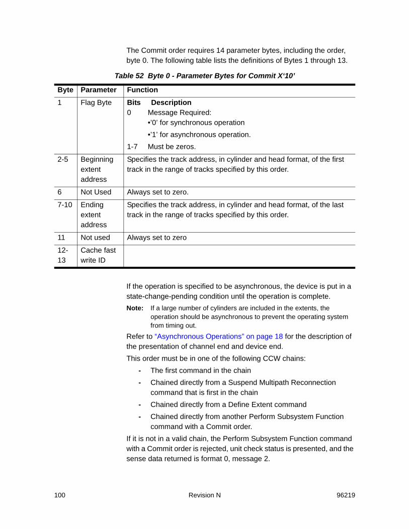
100 Revision N 96219
The Commit order requires 14 parameter bytes, including the order, byte 0. The following table lists the definitions of Bytes 1 through 13.
If the operation is specified to be asynchronous, the device is put in a state-change-pending condition until the operation is complete.Note: If a large number of cylinders are included in the extents, the
operation should be asynchronous to prevent the operating system from timing out.
Refer to “Asynchronous Operations” on page 18 for the description of the presentation of channel end and device end.This order must be in one of the following CCW chains:
- The first command in the chain- Chained directly from a Suspend Multipath Reconnection
command that is first in the chain- Chained directly from a Define Extent command- Chained directly from another Perform Subsystem Function
command with a Commit order.If it is not in a valid chain, the Perform Subsystem Function command with a Commit order is rejected, unit check status is presented, and the sense data returned is format 0, message 2.
Table 52 Byte 0 - Parameter Bytes for Commit X‘10’
Byte Parameter Function1 Flag Byte Bits Description
0 Message Required:•’0’ for synchronous operation•’1’ for asynchronous operation.
1-7 Must be zeros.
2-5 Beginning extent address
Specifies the track address, in cylinder and head format, of the first track in the range of tracks specified by this order.
6 Not Used Always set to zero.
7-10 Ending extent address
Specifies the track address, in cylinder and head format, of the last track in the range of tracks specified by this order.
11 Not used Always set to zero
12-13
Cache fast write ID
96219 Revision N 101
• Only a Perform Subsystem Function command with a Commit order or a Read Message ID command can be chained after a Commit order. A Read Message ID command can be chained only if the Message Required bit is set on for at least one of the Commit orders in the chain. If any command other than a Perform Subsystem Function with a Commit order or a Read Message ID is chained after this order, the command is terminated, unit check status is presented, and the sense data returned is format 0, message 2.
• The cylinder and head values in Bytes 2 through 5 (the beginning extent) and 7 through 10 (the ending extent) must be valid primary track addresses for the addressed device. The ending extent must be greater than or equal to the beginning extent. Bits 1 through 7 in the flag byte are always set to zero. If these conditions are not met, the Perform Subsystem Function command is rejected, unit check status is presented, and the sense data returned is format 0, message 4.
• If this order is preceded by a Define Extent command and the tracks specified in this command are not within the extent defined by the Define Extent command, this command is terminated and unit check status (file protected) is presented.
• The cache fast write ID (Bytes 12 and 13) must contain the current cache fast write ID of the subsystem. If Bytes 12 and 13 are zero, the command is rejected, unit check status is presented, and the sense data returned is format 0, message 4.
• If Bytes 12 and 13 are not zero, but do not contain the current cache fast write ID for the subsystem, the command is rejected, unit check status is presented, and the sense data returned is format F, message 6.
• If the chain has only one Commit order, the Message Required bit (byte 1, bit 0) determines if the order is synchronous or asynchronous. If the Message Required bit is ’0’ the operation is synchronous. If the Message Required bit is ’1’ the operation is asynchronous.
• If there are multiple Commit orders in a chain, the Message Required bit determines which of the Commit orders in the chain are synchronous or asynchronous. If the Message Required bit is ’1’ in any Commit order, the remainder of the Commit orders in the chain run asynchronously.
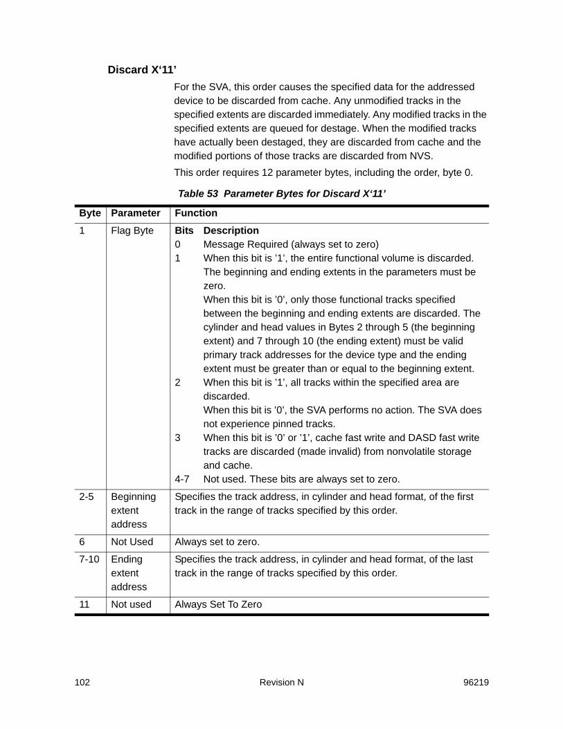
102 Revision N 96219
Discard X‘11’For the SVA, this order causes the specified data for the addressed device to be discarded from cache. Any unmodified tracks in the specified extents are discarded immediately. Any modified tracks in the specified extents are queued for destage. When the modified tracks have actually been destaged, they are discarded from cache and the modified portions of those tracks are discarded from NVS.This order requires 12 parameter bytes, including the order, byte 0.
Table 53 Parameter Bytes for Discard X‘11’
Byte Parameter Function1 Flag Byte Bits Description
0 Message Required (always set to zero) 1 When this bit is ’1’, the entire functional volume is discarded.
The beginning and ending extents in the parameters must be zero. When this bit is ’0’, only those functional tracks specified between the beginning and ending extents are discarded. The cylinder and head values in Bytes 2 through 5 (the beginning extent) and 7 through 10 (the ending extent) must be valid primary track addresses for the device type and the ending extent must be greater than or equal to the beginning extent.
2 When this bit is ’1’, all tracks within the specified area are discarded. When this bit is ’0’, the SVA performs no action. The SVA does not experience pinned tracks.
3 When this bit is ’0’ or ’1’, cache fast write and DASD fast write tracks are discarded (made invalid) from nonvolatile storage and cache.
4-7 Not used. These bits are always set to zero.
2-5 Beginning extent address
Specifies the track address, in cylinder and head format, of the first track in the range of tracks specified by this order.
6 Not Used Always set to zero.
7-10 Ending extent address
Specifies the track address, in cylinder and head format, of the last track in the range of tracks specified by this order.
11 Not used Always Set To Zero

96219 Revision N 103
The storage path presents channel end when it validates the parameters. Device end occurs when all of the unmodified tracks in the specified extents have been discarded from cache and all of the modified tracks in the specified extents have been queued for destage.This order must be in one of the following CCW chains:
- The first command in the chain - Chained directly from a Suspend Multipath Reconnection
command that is first in the chain - Chained directly from a Define Extent command - Chained directly from another Perform Subsystem Function
Command with a Discard order.If it is not in a valid chain, the Perform Subsystem Function command with a Discard order is rejected, unit check status is presented, and the sense data returned is format 0, message 2.• Only another Perform Subsystem Function command with a
Discard order may be chained from a Perform Subsystem Function command with a Discard order. If any other command is chained from this command, the command is terminated, unit check status is presented, and the sense data returned is format 0, message 2.
• The flag byte and the extent addresses must be valid, or the Perform Subsystem Function command is rejected, unit check status is presented, and the sense data returned is format 0, message 4.
• If this order is preceded by a Define Extent command and the specified extent is not in the extent defined by the Define Extent command, this command is terminated and unit check status (file protected) is presented.
Prepare for Read Subsystem Data X‘18’This order specifies the data that is returned for the next command in the chain (a Read Subsystem Data command). This order requires 12 parameter bytes, including the order, byte 0. The following table defines Bytes 1 through 11.

104 Revision N 96219
Table 54 Parameter Bytes for Prepare for Read Subsystem Data X‘18’
Byte Parameter Function1 Flag Byte Must be zero.
2-5 Reserved Must be zeros.
6 Suborder that defines the data to be returned
Value Description00 The status of the storage paths in the subsystem.01 The subsystem statistics.02 The current cache fast write ID.03 An attention message for this path group for the addressed
device. If the message identifier is zero, the message returned is any message waiting to be sent to the host. If the message identifier in parm Bytes 8 through 11 is not zero, the storage path returns the current state of the asynchronous operation associated with the message identifier, if it finds one that matches. If the storage path does not have a message. it returns a ’no message’ message.
04 Not Used05 The addresses of the next eight pinned tracks on the
addressed device started at the track specified in Bytes 8 through 11. The SVA accepts this order, but indicates “no pinned tracks.”
06-FF Not Used
7 Depends upon the value in Byte 6:Byte 6 Description00 Must be zero01 Scope of statistics to be returned. If zero, the storage path
prepares only a set of statistics for the addressed device. If X’FF’, the storage path prepares statistics for all the devices in the subsystem.
02-FF Must be zeros

96219 Revision N 105
The storage path presents channel end and device end when it validates and stores the parameters.The following conditions apply to this order:• The parameters for the Prepare to Read Subsystem Data order
must be valid. Valid parameters are as follows:- The flag byte must be zero. - Parameter byte 6 must contain a valid suborder. If the suborder
is not X’01’, byte 7 must be X’00’. If the suborder is X’01’, byte 7 must be either X’00’ or X’FF’.
- For suborders other than X’03’ or X’05’, Bytes 8 through 11 must be zero. If the suborder is X’05’, Bytes 8 through 11 must contain a valid user address (cylinder and head) for the device. If the device type is unknown, this check is bypassed and any value is accepted.
If any of these conditions are not met, the command is rejected, unit check status is presented, and the sense data returned is format 0, message 4.
• If the suborder is X’05’, cache must be available or pending. If this condition is not met, the command is rejected, unit check status is presented, and the sense data returned is format 0, message F.
• Only a Read Subsystem Data command can be chained from the Perform Subsystem Function command with this order. If any other command is chained from the command with this order, it is rejected, unit check status is presented, and the sense data
8-11 Depends upon the value in Byte 6:Byte 6 Description00 Must be zero01 0x00000000 - requests 96-byte records
0x01000000 - requests 192-byte records02 Must be zeros03 Message identifier04 Must be zeros05 The CCHH of the track used to start the search for the next
eight pinned tracks. The SVA accepts this order, but indicates “no pinned tracks”.
06-FF Must be zeros
Table 54 Parameter Bytes for Prepare for Read Subsystem Data X‘18’ (Continued)
Byte Parameter Function

106 Revision N 96219
returned is format 0, message 2. Refer to “Read Subsystem Data” on page 115 for the contents of each message.
Destage Modified Tracks X‘19’This order causes the SVA to destage all modified data in cache and NVS for the 64 functional devices of the functional storage control that contains the addressed device. Because the SVA consists of four functional storage controls, to destage all modified data in cache and NVS for the entire subsystem, the command must be issued to one functional device in each functional storage control. Note: This order can be used before subsystem shutdown to ensure that all
modified data is destaged. However, this is not necessary for the SVA.
This order requires two parameter bytes, the order byte 0 and the flag byte 1. The following table defines the flag byte.
Refer to “Asynchronous Operations” on page 18 for the description of thepresentation of channel end and device end.The following conditions apply to this order:• If the special Intercept condition is in effect, this order is rejected.• If bit 0 is ’on’, any command other than a Read Message ID
chained after this order is terminated, unit check status is presented, and the sense data returned is format 0, message 2.
• If bit 0 is ’off’, any command chained after this order is terminated, unit check status is presented, and the sense data returned is format 0, message 2).
• If bits 1 through 7 are not zeros, the command is terminated, unit check status is presented, and the sense data returned is format 0, message 4.
Table 55 Parameter Bytes for Destage Modified Tracks Order
Byte 1 Bits Function/Description 0 If this bit is ’on’ and a Read Message ID command is chained from this
command, the host making the request receives an attention interruption and a message.
1-7 Must be zeros.
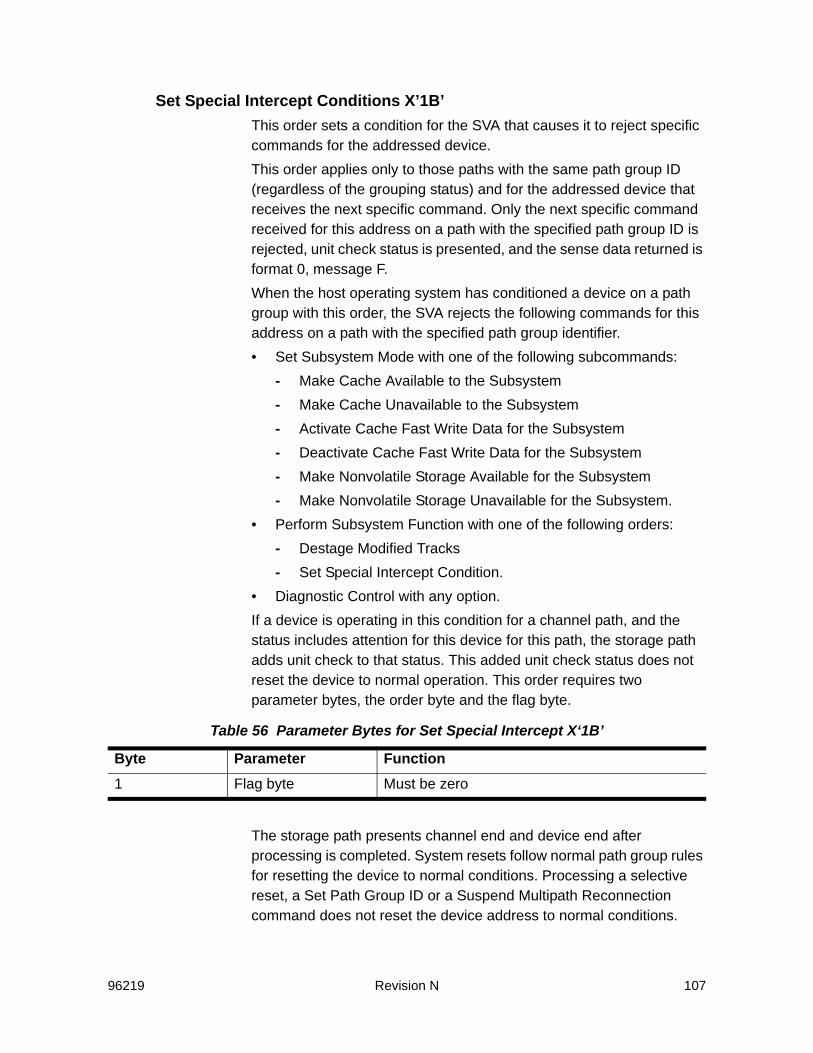
96219 Revision N 107
Set Special Intercept Conditions X’1B’This order sets a condition for the SVA that causes it to reject specific commands for the addressed device. This order applies only to those paths with the same path group ID (regardless of the grouping status) and for the addressed device that receives the next specific command. Only the next specific command received for this address on a path with the specified path group ID is rejected, unit check status is presented, and the sense data returned is format 0, message F.When the host operating system has conditioned a device on a path group with this order, the SVA rejects the following commands for this address on a path with the specified path group identifier.• Set Subsystem Mode with one of the following subcommands:
- Make Cache Available to the Subsystem - Make Cache Unavailable to the Subsystem - Activate Cache Fast Write Data for the Subsystem - Deactivate Cache Fast Write Data for the Subsystem - Make Nonvolatile Storage Available for the Subsystem - Make Nonvolatile Storage Unavailable for the Subsystem.
• Perform Subsystem Function with one of the following orders:- Destage Modified Tracks - Set Special Intercept Condition.
• Diagnostic Control with any option.If a device is operating in this condition for a channel path, and the status includes attention for this device for this path, the storage path adds unit check to that status. This added unit check status does not reset the device to normal operation. This order requires two parameter bytes, the order byte and the flag byte.
The storage path presents channel end and device end after processing is completed. System resets follow normal path group rules for resetting the device to normal conditions. Processing a selective reset, a Set Path Group ID or a Suspend Multipath Reconnection command does not reset the device address to normal conditions.
Table 56 Parameter Bytes for Set Special Intercept X‘1B’
Byte Parameter Function1 Flag byte Must be zero
108 Revision N 96219
The following conditions apply to this order:• This command must be the first command in the chain or must be
immediately preceded by a Suspend Multipath Reconnection command that is first in a chain. If this requirement is not met, the command is terminated and unit check status (invalid sequence) is presented.
• If any command is chained from this command, it is rejected, unit check status is presented, and the sense data returned is format 0, message 2.
• If this command addresses a device on an interface for which a path group has not been established, the command is rejected, unit check status is presented, and the sense data returned is format 0, message F.
• If the SVA receives less than two parameter bytes, the command is rejected, unit check status is presented, and the sense data returned is format 0, message 3.
• If the flag byte is not zero, the command is rejected, unit check status is presented, and the sense data returned is format 0, message 4.
SVASet Interface Identifier X‘B0’This order identifies the channel interface for which the SVA subsystem is to prepare a ’node-descriptor’ record. The record is read by a Read Subsystem Data command chained from this Perform Subsystem Function command.This command order is accepted if the addressed device is not installed or is not available. This order requires four parameter bytes, including the order and flag bytes.
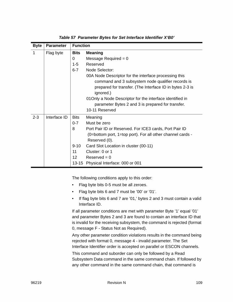
96219 Revision N 109
The following conditions apply to this order:• Flag byte bits 0-5 must be all zeroes.• Flag byte bits 6 and 7 must be ’00’ or ’01’.• If flag byte bits 6 and 7 are ’01,’ bytes 2 and 3 must contain a valid
Interface ID.If all parameter conditions are met with parameter Byte ’1’ equal ’01’ and parameter Bytes 2 and 3 are found to contain an interface ID that is invalid for the receiving subsystem, the command is rejected (format 0, message F - Status Not as Required).Any other parameter condition violations results in the command being rejected with format 0, message 4 - invalid parameter. The Set Interface Identifier order is accepted on parallel or ESCON channels.This command and suborder can only be followed by a Read Subsystem Data command in the same command chain. If followed by any other command in the same command chain, that command is
Table 57 Parameter Bytes for Set Interface Identifier X‘B0’
Byte Parameter Function1 Flag byte Bits Meaning
0 Message Required = 01-5 Reserved6-7 Node Selector:
00A Node Descriptor for the interface processing this command and 3 subsystem node qualifier records is prepared for transfer. (The Interface ID in bytes 2-3 is ignored.)
01Only a Node Descriptor for the interface identified in parameter Bytes 2 and 3 is prepared for transfer.
10-11 Reserved
2-3 Interface ID Bits Meaning0-7 Must be zero8 Port Pair ID or Reserved. For ICE3 cards, Port Pair ID
(0=bottom port, 1=top port). For all other channel cards - Reserved (0).
9-10 Card Slot Location in cluster (00-11) 11 Cluster: 0 or 112 Reserved = 013-15 Physical Interface: 000 or 001

110 Revision N 96219
rejected with format 0, message 2. If all chaining and parameter conditions are satisfied, a status of channel end and device end are presented.
Sense Subsystem Status
The Sense Subsystem Status command causes the SVA to send 40 bytes of information to the channel. If the CCW count is more than 40, only 40 bytes are transferred. If the CCW count is fewer than 40 bytes, only the specified number of bytes are transferred. The information contained in these bytes describes the status of the SVA subsystem and the addressed device.This command is accepted even if the device is not ready. Refer to “Status Presented To Commands” on page 36 for the operation of this command when other subsystem and device status conditions exist.
Table 58 Sense Subsystem Status Command, Mnemonic, and Hex Code
Command Mnemonic Hex CodeSense Subsystem Status SNSS 54
Table 59 Sense Subsystem Status Parameters
Byte Parameter Function0 Not Used Always zero
1 Device Unit Address
Device Unit Address
2 Number of Devices The number of devices for which the subsystem is maintaining statistics.
3 Number of Statistics sets per device
This byte contains X’01’
4 Overall caching status
Refer to page 112.
5 Overall nonvolatile storage status
Refer to page 113.
6-7 Length of performance statistics
The length in bytes of data read by a Read Subsystem Data command requesting performance data.Note: For non-ESCON channels, these bytes contain zeros,
denoting that the length is 96 bytes. For ESCON channels, these bytes contain 0x00C0, denoting that the length is 192 bytes.

96219 Revision N 111
The Sense Subsystem Status command is not valid in the following conditions:• If the command is issued in a Locate Record or Locate Record
Extended domain. In this case, the command is rejected, unit
8-9 Not Used Always zero
10-13
Configured cache capacity
Configured cache capacity in kilobytes.
14-17
Available cache capacity
The number of bytes of cache available to this subsystem for cache space in kilobytes. This is the total online space available to this subsystem for caching.
18-21
Pinned cache space
The number of bytes of pinned data in cache (data that cannot be transferred to DASD because of an error), in kilobytes.
22-25
Offline cache capacity
The number of bytes of cache unavailable to the storage director because of cache read failures in kilobytes. Note: The sum of the available cache capacity, pinned cache
capacity, and offline cache capacity is always less than the configured cache capacity. The difference in these two values reflects the amount of cache capacity that is never available for caching. This space is the space for subsystem control data and the space remaining after the storage director allocates as many track-slot segments as possible.
26-27
Addressed device status (Part 1)
Refer to page 113.
28-31
Configured nonvolatile storage capacity
Configured nonvolatile storage capacity available to this subsystem in kilobytes.
32-35
Pinned nonvolatile storage space
Nonvolatile storage capacity in bytes that is currently used by pinned data (data that cannot be transferred to DASD because of an error.)SVA
36 Addressed device status (Part 2)
Refer to page 114.
37 Reserved Always zero
38-39
Subsystem identifier
The subsystem identifier (SSID) for the functional storage control.
Table 59 Sense Subsystem Status Parameters (Continued)
Byte Parameter Function

112 Revision N 96219
check status. is presented, and the sense data returned is format 0, message 2.
• If the command is not the first command in a chain or chained directly from a Read Device Characteristics, a Read Configuration Data, or a Suspend Multipath Reconnection command. If it is preceded by a Suspend Multipath Reconnection command, the Suspend Multipath Reconnection command must be the first command in the chain. In any of these cases, the command is rejected, unit check status is presented, and the sense data returned is format 0, message 2.
• If any command is chained from the Sense Subsystem Status command. In this case, that command is rejected, unit check status is presented, and the sense data returned is format 0, message 2. However, the rejection of this chained command reject does not affect the operation of the Sense Subsystem Status command.
Ending StatusChannel end and device end are presented when data transfer is completed.
SNSS Byte 4 - Overall Caching StatusTwo fields define the subsystem caching status conditions that are associated with the caching status of the storage path receiving the command.
Table 60 Subsystem Caching Status
Bits Description0-2 Subsystem Caching Status
Bit Value Description000 Active: cache is active.001 Pending active: cache is being activated.010 Offline: an internal error has made cache unavailable. (Not applicable for the
SVA.)100 Deactivated: cache has been deactivated at the request of the host program
or the SVA support processor.110 Pending-off in process: a command to deactivate cache was received, but
an operation is still in process.111 Pending off failure: a command to deactivate cache was received, but
destaging failed. (Not applicable for the SVA.)
3 On Disabled for maintenance: cache is offline. (Not applicable for the SVA.)

96219 Revision N 113
SNSS Byte 5 - Overall Nonvolatile Storage (NVS) StatusTwo fields show the status of nonvolatile storage.
SNSS Bytes 26 and 27 - Addressed Device Status (Part 1)These bytes define the caching status and DASD fast write status for the addressed device. This status information is also in the data returned by the Read Subsystem Data command, if that command is preceded in the chain by a Perform Subsystem Function command
4-5 Not used (always zeros)
6 On IML device is not available. (Not applicable for the SVA.)
7 ON Cache fast write has been deactivated.
Bits Bit Value Description0-1 Subsystem NVS Status
00 Active: NVS is activated.
01 Failed: an internal error has made NVS unavailable. (Not applicable for the SVA.)
10 Unavailable: NVS has been deactivated at the request of the host program or the SVA support processor. All data has been discarded or successfully destaged.
11 Pending: a request to make NVS unavailable has been received, but an operation is in process.
2 Not Used Always zero
3 On Disable for maintenance: NVS is offline. (Not applicable for the SVA.)
4 On Pending: NVS is unavailable because of an error. (Not applicable for the SVA.)
5-7 Not Used Always set to zero
Table 60 Subsystem Caching Status
Bits Description
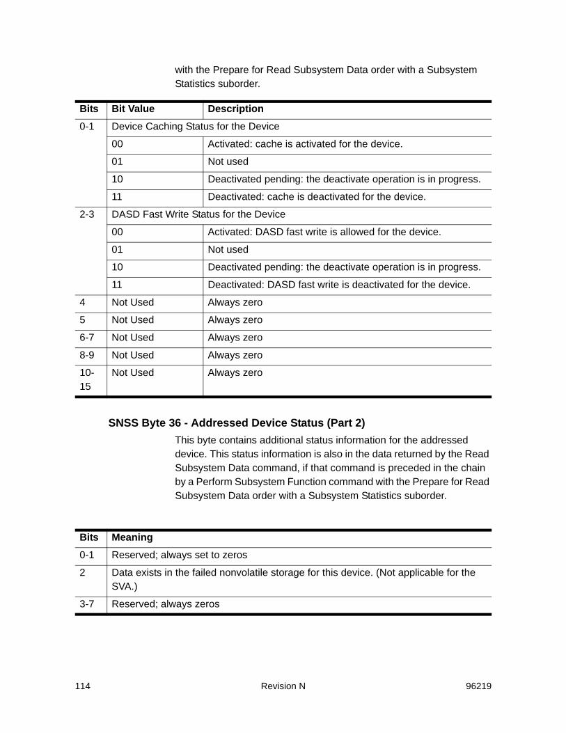
114 Revision N 96219
with the Prepare for Read Subsystem Data order with a Subsystem Statistics suborder.
SNSS Byte 36 - Addressed Device Status (Part 2)This byte contains additional status information for the addressed device. This status information is also in the data returned by the Read Subsystem Data command, if that command is preceded in the chain by a Perform Subsystem Function command with the Prepare for Read Subsystem Data order with a Subsystem Statistics suborder.
Bits Bit Value Description0-1 Device Caching Status for the Device
00 Activated: cache is activated for the device.
01 Not used
10 Deactivated pending: the deactivate operation is in progress.
11 Deactivated: cache is deactivated for the device.
2-3 DASD Fast Write Status for the Device
00 Activated: DASD fast write is allowed for the device.
01 Not used
10 Deactivated pending: the deactivate operation is in progress.
11 Deactivated: DASD fast write is deactivated for the device.
4 Not Used Always zero
5 Not Used Always zero
6-7 Not Used Always zero
8-9 Not Used Always zero
10-15
Not Used Always zero
Bits Meaning0-1 Reserved; always set to zeros
2 Data exists in the failed nonvolatile storage for this device. (Not applicable for the SVA.)
3-7 Reserved; always zeros
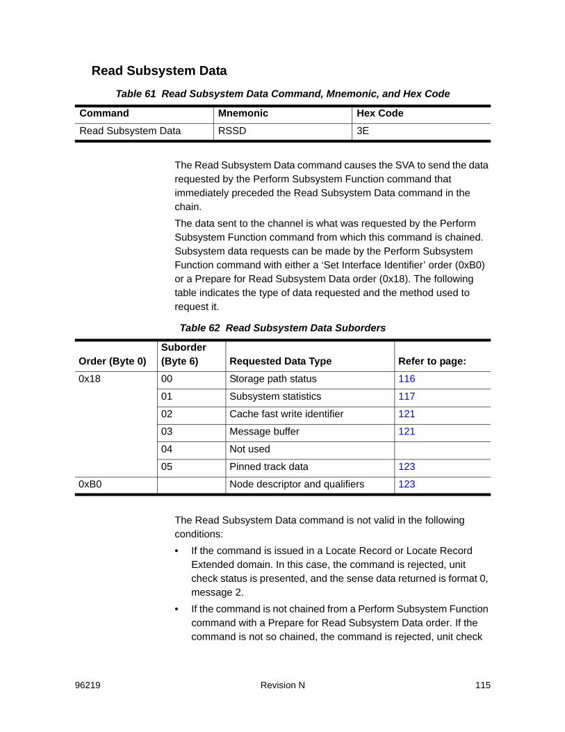
96219 Revision N 115
Read Subsystem Data
The Read Subsystem Data command causes the SVA to send the data requested by the Perform Subsystem Function command that immediately preceded the Read Subsystem Data command in the chain.The data sent to the channel is what was requested by the Perform Subsystem Function command from which this command is chained. Subsystem data requests can be made by the Perform Subsystem Function command with either a ‘Set Interface Identifier’ order (0xB0) or a Prepare for Read Subsystem Data order (0x18). The following table indicates the type of data requested and the method used to request it.
The Read Subsystem Data command is not valid in the following conditions:• If the command is issued in a Locate Record or Locate Record
Extended domain. In this case, the command is rejected, unit check status is presented, and the sense data returned is format 0, message 2.
• If the command is not chained from a Perform Subsystem Function command with a Prepare for Read Subsystem Data order. If the command is not so chained, the command is rejected, unit check
Table 61 Read Subsystem Data Command, Mnemonic, and Hex Code
Command Mnemonic Hex CodeRead Subsystem Data RSSD 3E
Table 62 Read Subsystem Data Suborders
Order (Byte 0)Suborder (Byte 6) Requested Data Type Refer to page:
0x18 00 Storage path status 116
01 Subsystem statistics 117
02 Cache fast write identifier 121
03 Message buffer 121
04 Not used
05 Pinned track data 123
0xB0 Node descriptor and qualifiers 123

116 Revision N 96219
status is presented, and the sense data returned is format 0, message 2.
If the CCW count is more than the number of bytes specified for the data, only the number of data bytes are transferred. If the CCW count is fewer than the number of bytes specified for the requested data, only the specified number of bytes are transferred.Only a Perform Subsystem Function command with a Prepare for Read Subsystem Data order can be chained from this command. If any other command is chained from this command, the command is rejected, unit check status is presented, and the sense data returned is format 0, message 2.
Ending StatusChannel end and device end are presented when the data transfer is completed.
Storage Path StatusWhen the Perform Subsystem Function command has the order Prepare for Read Subsystem Data with Byte 6 equal to X’00’, a 16-byte record containing four bytes of path status for each storage path is read. The following table defines the contents of a record.
Table 63 Storage Path Status
Byte Parameter Function0-3 Status of Storage
Path 0Byte Meaning0 Storage Path/Device Status
Bit Meaning0When this bit is ’1’, Bytes 1 through 3 contain valid
values. When this bit is ’0’, this storage path is not installed on this subsystem.
1The device attaches through this storage path.2This storage path is disabled. When this bit is ’1’,
Bytes 1 through 3 are invalid.3The device has a permanent or internal fence from
this storage path. Always 0 for the SVA.4-7The ID of the channel requesting status (0 for
channel A, 1 for channel B, etc.) (channel number in cluster).
1-2 Bit map of channels enabled in this storage cluster.3 Reserved; always set to zero.

96219 Revision N 117
Subsystem StatisticsWhen the Perform Subsystem Function command has the order Prepare for Read Subsystem Data with Byte 6 equal to X’01’, the statistics record for one or all the devices attached to the functional storage control is read. The following description of the data represents a single record. If a Perform Subsystem Function command with a Prepare for Read Subsystem Data order requests multiple records, those records return as a single entity.Note: The number of devices and the length of the record are included in
Bytes 2, 6, and 7 of the data read by the Sense Subsystem Status command. Non-ESCON channels transfer only 96 bytes, ESCON channels transfer 96 or 192 bytes.
The records are in ascending sequence by channel address with a record for each address (the device does not have to exist or have any data).For these statistics, a channel operation is defined to start at a Locate Record or Seek command and continue until the next Locate Record or Seek command, or until the end of the CCW chain.When the Define Extent command in a channel operation specifies inhibit cache loading, how the channel operation is counted depends on whether or not the operation accesses DASD. If DASD is not accessed because the operation is a read or write hit or a predictable write, the operation is not counted as inhibit cache loading but is counted as either a normal cache replacement or a cache fast write operation. If the operation accesses DASD, the operation is counted as an inhibit cache loading request.If the channel operation specifies sequential access with cache fast write data, the operation is counted as a cache fast write data operation instead of a sequential access operation.This data is kept in shared memory. If cache is made unavailable (logically) to the subsystem with a Set Subsystem Mode, or if a Diagnostic Control or Diagnostic Initialize Subsystem command is
4-7 Status of Storage Path 1
Same byte/bit description as Bytes 0-3 described above.
8-11 Status of Storage Path 2
Same byte/bit description as Bytes 0-3 described above.
12-15
Status of Storage Path 3
Same byte/bit description as Bytes 0-3 described above.
Table 63 Storage Path Status

118 Revision N 96219
received, the counters are reset to zero. If cache is unavailable (logically) to the subsystem, only Bytes 0 through 3 and bytes 94 and 95 are valid.Note: Refer to , “Read Subsystem Data (RSSD) Differences” on page 233,
for additional details concerning the statistics record that the SVA returns versus the statistics record that an IBM 3390 returns.
Table 64 Subsystem Statistics
Bytes DescriptionRefer to Page:
0 When Byte 0, bit 0 is ’1’, cache is not available and all counts are zero.
1 Device unit address to which the data pertains.
2-3 Addressed Device Status - Part 1. The same data as Bytes 26 and 27 of the Sense Subsystem Status command.
113
4-7 Search or read normal I/O requests. The number of channel operations that had at least one search or read command, but no write commands. If the operation had a Define Extent command, it specified either normal cache replacement or inhibit cache loading, which did not access DASD. The Define Extent command, if present, did not include a cache fast write attribute.
237
8-11 Search or read normal I/O request hits. The number of search or read caching channel operations that did not move any data to or from a device. If the operation had a Define Extent command, it specified either normal cache replacement or inhibit cache loading. The Define Extent command, if present, did not include a cache fast write attribute.
239
12-15 Write normal I/O requests. The number of channel operations that had at least one write command. If the operation had a Define Extent command, it did not include a cache fast write attribute.
240
16-19 DASD fast write I/O request hits. The number of channel operations that had at least one write command. The operation did not cause the concurrent transfer of data to or from a device. If the operation had a Define Extent command, it did not include a cache fast write attribute.
242
20-23 Search or read sequential I/O requests. The number of channel operations that had at least one search or read command and no write commands. The Define Extent command specified sequential access and not cache fast write.
237

96219 Revision N 119
24-27 Search or read sequential I/O request hits. The number of channel operations that had at least one search or read command and no write commands. The operation did not cause the concurrent transfer of data to or from a device. The Define Extent command specified sequential access and not cache fast write.
239
28-31 Write sequential I/O requests. The number of channel operations that had at least one write command. The Define Extent command specified sequential access and not cache fast write.
240
32-35 DASD fast write sequential I/O request hits. The number of channel operations that had at least one write command. The operation did not cause the concurrent transfer of data to or from a device. The Define Extent command specified sequential access and not cache fast write.
242
36-39 Search or read cache fast write I/O requests. The number of channel operations that had at least one search or read command and no write commands. The Define Extent command specified cache fast write and did not specify bypass cache. If the Define Extent command specified inhibit cache loading, DASD was not accessed.
243
40-43 Search or read cache fast write I/O request hits. The number of channel operations that had at least one search or read command and no write commands. The Define Extent command specified cache fast write and did not specify bypass cache. The operation did not cause the concurrent transfer of data to or from a device.
250
44-47 Cache fast write I/O requests. The number of channel operations that had at least one write command. The Define Extent command specified cache fast write and did not specify bypass cache. If the Define Extent command specified inhibit cache loading, DASD was not accessed.
252
48-51 Cache fast write I/O request hits. The number of channel operations that had at least one write command. The Define Extent command specified cache fast write and did not specify bypass cache. The operation did not cause the concurrent transfer of data to or from a device.
254
Table 64 Subsystem Statistics (Continued)
Bytes DescriptionRefer to Page:
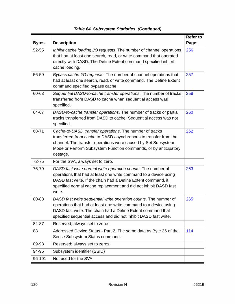
120 Revision N 96219
52-55 Inhibit cache loading I/O requests. The number of channel operations that had at least one search, read, or write command that operated directly with DASD. The Define Extent command specified inhibit cache loading.
256
56-59 Bypass cache I/O requests. The number of channel operations that had at least one search, read, or write command. The Define Extent command specified bypass cache.
257
60-63 Sequential DASD-to-cache transfer operations. The number of tracks transferred from DASD to cache when sequential access was specified.
258
64-67 DASD-to-cache transfer operations. The number of tracks or partial tracks transferred from DASD to cache. Sequential access was not specified.
260
68-71 Cache-to-DASD transfer operations. The number of tracks transferred from cache to DASD asynchronous to transfer from the channel. The transfer operations were caused by Set Subsystem Mode or Perform Subsystem Function commands, or by anticipatory destage.
262
72-75 For the SVA, always set to zero.
76-79 DASD fast write normal write operation counts. The number of operations that had at least one write command to a device using DASD fast write. If the chain had a Define Extent command, it specified normal cache replacement and did not inhibit DASD fast write.
263
80-83 DASD fast write sequential write operation counts. The number of operations that had at least one write command to a device using DASD fast write. The chain had a Define Extent command that specified sequential access and did not inhibit DASD fast write.
265
84-87 Reserved; always set to zeros.
88 Addressed Device Status - Part 2. The same data as Byte 36 of the Sense Subsystem Status command.
114
89-93 Reserved; always set to zeros.
94-95 Subsystem identifier (SSID)
96-191 Not used for the SVA
Table 64 Subsystem Statistics (Continued)
Bytes DescriptionRefer to Page:
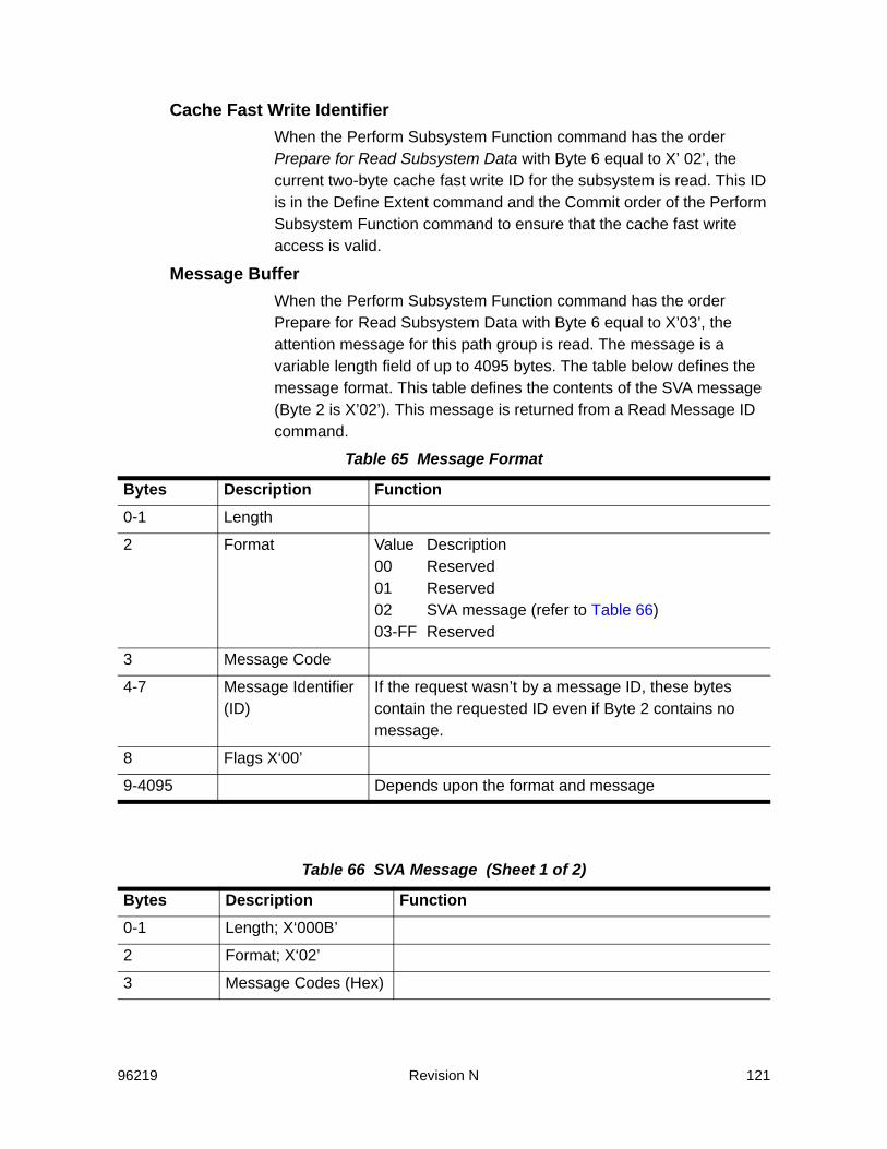
96219 Revision N 121
Cache Fast Write IdentifierWhen the Perform Subsystem Function command has the order Prepare for Read Subsystem Data with Byte 6 equal to X’ 02’, the current two-byte cache fast write ID for the subsystem is read. This ID is in the Define Extent command and the Commit order of the Perform Subsystem Function command to ensure that the cache fast write access is valid.
Message BufferWhen the Perform Subsystem Function command has the order Prepare for Read Subsystem Data with Byte 6 equal to X’03’, the attention message for this path group is read. The message is a variable length field of up to 4095 bytes. The table below defines the message format. This table defines the contents of the SVA message (Byte 2 is X’02’). This message is returned from a Read Message ID command.
Table 65 Message Format
Bytes Description Function0-1 Length
2 Format Value Description00 Reserved01 Reserved02 SVA message (refer to Table 66)03-FF Reserved
3 Message Code
4-7 Message Identifier (ID)
If the request wasn’t by a message ID, these bytes contain the requested ID even if Byte 2 contains no message.
8 Flags X‘00’
9-4095 Depends upon the format and message
Table 66 SVA Message (Sheet 1 of 2)
Bytes Description Function0-1 Length; X‘000B’
2 Format; X‘02’
3 Message Codes (Hex)

122 Revision N 96219
3 Message Code Value00
DescriptionNot used
01 Delayed response message
02-FF Reserved
4-7 Message Identifier (ID) If the request was sent by a message ID, these bytes contain the requested ID. If the specific asynchronous operation completed before device end was presented, these bytes are zeros.
8 Flags X‘00’
9 Operation Completion Status
See Table 67
10 If the message is in response to a Make Cache Available order, bits 0 through 3 are a bit map of caching storage paths. Each bit is ’1’ to show what physical path is caching. For example, if bit 0 is ’1’, storage path 0 is caching.
Table 67 Operation Completion Status
Value Description00 Successful completion of a host-initiated asynchronous operation associated
with the message ID specified in Bytes 4 through 7. All modified data has been queued for destage and the “no modified data” indicator is set.
01 Completion with errors of a host-initiated asynchronous operation associated with the message ID specified in Bytes 4 through 7. The resources necessary to start the operation are available, but portions of the operation failed.Errors were reported by a unit check of an I/O operation to the device that was performing the asynchronous operation. The sense information from this unit check defines the data associated with the asynchronous error. Examine a merged EREP report for all attached systems to determine the significance of the failure(s).
Table 66 SVA Message (Sheet 2 of 2)
Bytes Description Function

96219 Revision N 123
Pinned-Track DataWhen the Perform Subsystem Function command has the order Prepare for Read Subsystem Data with Byte 6 equal to X’05’, pinned-track data is returned. The SVA does not have pinned data. Thirty-two bytes of 0xF are returned.
Node DescriptorWhen the Perform Subsystem Function command has the order of “Set Interface Identifier” (order 0xB0), a 32-byte Node Descriptor of the identified interface is sent to the channel. The following table defines the format of the Node Descriptor. Note: “Port Pair” refers to the two ports associated with each Channel
Interface Processor (CIP) on an ICE3 ESCON channel card.
02 A failed operation from a host-initiated asynchronous operation associated with the message ID specified in Bytes 4 through 7. The host’s request for information is on a specific message, but the operation that owes the message is still in progress. The errors were reported by a unit check of an I/O operation to the device that was doing the asynchronous operation. The sense information from this unit check defines the data associated with the asynchronous error. Examine a merged EREP report for all attached systems to determine the exact failure.
03 Pending status returned by the Read Message ID command. This message code is returned if the operation for which the host has requested information is still in progress, or if the host requested information for the specified ID with a Perform Subsystem Function and the Read Subsystem Data command.
04 Reserved.
05 The ’no modified data’ indicator is not set (due to activity during destage), although a Destage Modified Tracks order completed successfully.
06-FF Not used.
Table 67 Operation Completion Status (Continued)

124 Revision N 96219
Table 68 Node Descriptor Record
Bytes Description Function0 Flags Bits
0-2
34-7
DescriptionNode ID Validity:000 Node ID is valid001 Node ID is valid, but may not be current010 Node is not valid011-111 ReservedNode TypeReserved
1-3 Node Parameters
Byte123
DescriptionReserved: 0x00Node Class: SVA = 0x01 (DASD)Reserved: 0x00
4-9 Storage Control Type
F0F0F0E5F2E7 (SVA in EBCDIC)
10-12 Model Number 0xF0F0F2 (002)
13-15 Manufacturer 0xE2E3D2 - (STK)
16-17 Plant of Manufacture
0xF0F1- (01-Louisville)0xF0F2 - (02-Puerto Rico)
18-29 Sequence Number
Unit sequence number in EBCDIC - the control unit assembly serial number, which is riveted to the front of the frame in the upper right corner.
30-31 Tag ID (Interface)
00xx, where xx:Bit Meaning0 Port Pair ID or Reserved. For ICE3 cards:
•0 = bottom port•1 = top portSee “Note” above.For other ESCON channel cards: reserved (0).
1-2 Card slot location 00-11(0-3) in cluster3 Cluster (0 - 1)4 Reserved (0)5-7 Physical Interface (CIP ID on card)(000 or 001)
•000 = Upper CIP on card•001 = Lower CIP on card

96219 Revision N 125
Node QualifiersIf the flag byte of the Perform Subsystem Function command was ‘00’, three 32-byte Node Qualifiers are also sent to the channel. A Node Qualifier uses ranges to describe the protocol for each interface on the subsystem. These ranges are described with 8 bytes; the first 4 bytes describe the first interface of a range, the second 4 bytes describe the last interface of a range. All fields that are not required by the configuration is set to zeros. Note: “Port Pair” refers to the two ports associated with each Channel
Interface Processor (CIP) on an ICE3 ESCON channel card.
Table 69 Node Qualifiers
Bytes Description Values32 Flags Zeros
33-39 Reserved Zeros
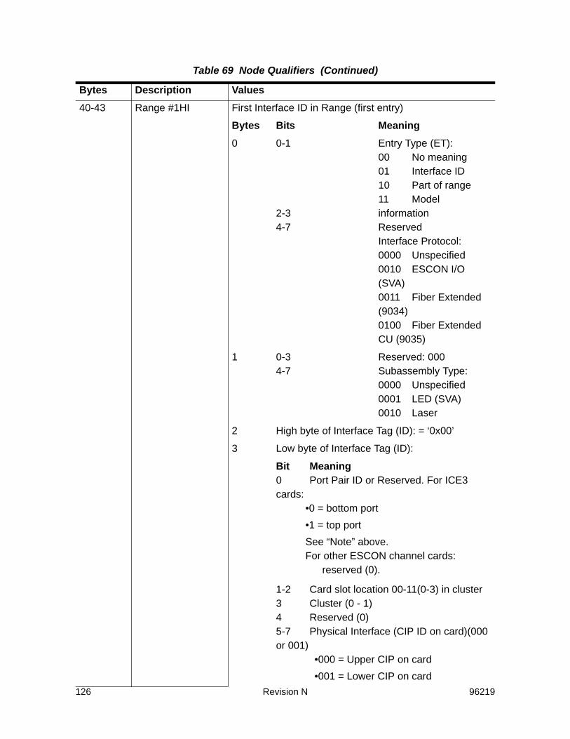
126 Revision N 96219
40-43 Range #1HI First Interface ID in Range (first entry)
Bytes Bits Meaning0 0-1
2-34-7
Entry Type (ET):00 No meaning01 Interface ID10 Part of range11 Model informationReservedInterface Protocol:0000 Unspecified0010 ESCON I/O (SVA)0011 Fiber Extended (9034)0100 Fiber Extended CU (9035)
1 0-34-7
Reserved: 000Subassembly Type:0000 Unspecified0001 LED (SVA)0010 Laser
2 High byte of Interface Tag (ID): = ‘0x00’
3 Low byte of Interface Tag (ID):
Bit Meaning0 Port Pair ID or Reserved. For ICE3 cards:
•0 = bottom port•1 = top portSee “Note” above.For other ESCON channel cards:
reserved (0).
1-2 Card slot location 00-11(0-3) in cluster3 Cluster (0 - 1)4 Reserved (0)5-7 Physical Interface (CIP ID on card)(000 or 001)
•000 = Upper CIP on card•001 = Lower CIP on card
Table 69 Node Qualifiers (Continued)
Bytes Description Values
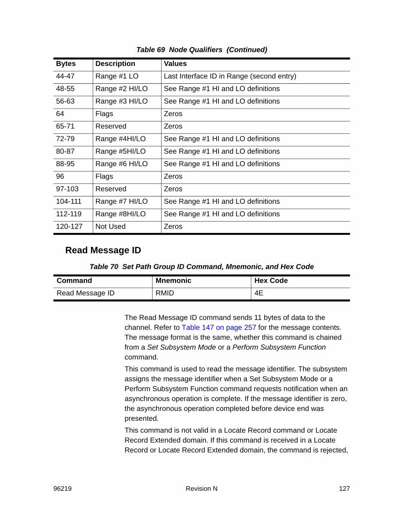
96219 Revision N 127
Read Message ID
The Read Message ID command sends 11 bytes of data to the channel. Refer to Table 147 on page 257 for the message contents. The message format is the same, whether this command is chained from a Set Subsystem Mode or a Perform Subsystem Function command.This command is used to read the message identifier. The subsystem assigns the message identifier when a Set Subsystem Mode or a Perform Subsystem Function command requests notification when an asynchronous operation is complete. If the message identifier is zero, the asynchronous operation completed before device end was presented.This command is not valid in a Locate Record command or Locate Record Extended domain. If this command is received in a Locate Record or Locate Record Extended domain, the command is rejected,
44-47 Range #1 LO Last Interface ID in Range (second entry)
48-55 Range #2 HI/LO See Range #1 HI and LO definitions
56-63 Range #3 HI/LO See Range #1 HI and LO definitions
64 Flags Zeros
65-71 Reserved Zeros
72-79 Range #4HI/LO See Range #1 HI and LO definitions
80-87 Range #5HI/LO See Range #1 HI and LO definitions
88-95 Range #6 HI/LO See Range #1 HI and LO definitions
96 Flags Zeros
97-103 Reserved Zeros
104-111 Range #7 HI/LO See Range #1 HI and LO definitions
112-119 Range #8HI/LO See Range #1 HI and LO definitions
120-127 Not Used Zeros
Table 70 Set Path Group ID Command, Mnemonic, and Hex Code
Command Mnemonic Hex CodeRead Message ID RMID 4E
Table 69 Node Qualifiers (Continued)
Bytes Description Values
128 Revision N 96219
unit check status is presented, and the sense data returned is format 0, message 2.This command can be chained directly from a Set Subsystem Mode or a Perform Subsystem Function command that requests a message. If not in a specified chain, the command is rejected, unit check status is presented, and the sense data returned is format 0, message 2.This command must be the last command in the chain. Any command chained from a Read Message ID command is rejected, unit check status is presented, and the sense data returned is format 0, message 2.Channel end and device end status is presented when the message ID transfer is completed.
96219 Revision N 129
3ECKD 32-Byte Sense Data
The SVA sense data consists of 32 bytes of information that identifies the cause of the last unit check status presented for a functional device on a channel interface. Sense data also contains information that may be required for system error recovery initiated by host error recovery procedures (ERPs).When sense byte 27, bit 0 is “0”, the sense data is formatted as ECKD 32-byte sense data. ECKD 32-byte sense data is the new generation of sense data designed to accommodate new storage subsystem features and conditions.The SVA employs ECKD 32-byte sense data to report:• All SIMs on all device addresses• All equipment checks, data checks, and usage statistics for a
functional device configured as a 3390-type device.
Sense Byte Structure and DescriptionThe SVA sends sense data to the channel when it receives a Sense command. If the Sense command is not preceded by a unit check status for the same device on the same channel interface, the sense is 24-byte compatibility, format 0 message 0, with sense bytes 0 through 3 equal to zero (refer to , “24-Byte Compatibility Sense Data” on page 151.)In ECKD 32-byte sense data, the general error classification is identified by an exception class identified in the high nibble of sense byte 22. Host error recovery procedures are determined by the contents of sense byte 25, which contains the program action code that indicates the type of action to take.The Controller reports all specific back-end errors to the SVA support processor (ISP) in a failure report. The ISP logs the errors and generates service information messages (SIMs), as necessary. A SIM may identify a primary suspect field-replaceable unit (FRU) — the FRU that may have caused the error condition. If an error condition is detected while the SVA is not communicating with a channel or after ending status is presented for a CCW (channel command word) chain,

130 Revision N 96219
the errors are reported with a subsequent channel-initiated selection. SIMs are reported in this fashion.Note: All devices referred to in this chapter are functional devices unless
they are otherwise specified as physical devices. All tracks referred to in this chapter are functional tracks unless they are otherwise specified as physical or array tracks.
ECKD 32-Byte Sense Data Summary
Table 71 ECKD 32-Byte Sense Information Summary
Byte Bit Meaning0 0 Reserved for the SVA
1 Intervention Required
2. Reserved
3 Equipment Check
4 Data Check
5 Reserved
6 Not used
7 Reserved for the SVA
1 0 Permanent Error
1 Reserved for the SVA
2 Reserved
3 Message to Operator
4 Reserved
5-7 Reserved for the SVA
2 — Functional storage control type code, or, for certain SIMs, Environment Data Present
3 — Remaining intent count (all exception classes except class 6) Reserved for the SVA (exception class 6)
4 — Device Address
5 — Device type code
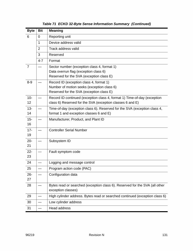
96219 Revision N 131
6 0 Reporting unit
1 Device address valid
2 Track address valid
3 Reserved
4-7 Format
7 — Sector number (exception class 4, format 1) Data overrun flag (exception class 6) Reserved for the SVA (exception class E)
8-9 — Record ID (exception class 4, format 1) Number of motion seeks (exception class 6) Reserved for the SVA (exception class E)
10-12
— Record ID continued (exception class 4, format 1) Time-of-day (exception class 6) Reserved for the SVA (exception classes 6 and E)
13-14
— Time-of-day (exception class 6). Reserved for the SVA (exception class 4, format 1 and exception classes 6 and E)
15-16
— Manufacturer, Product, and Plant ID
17-19
— Controller Serial Number
20-21
— Subsystem ID
22-23
— Fault symptom code
24 — Logging and message control
25 — Program action code (PAC)
26-27
— Configuration data
28 — Bytes read or searched (exception class 6). Reserved for the SVA (all other exception classes)
29 — High cylinder address. Bytes read or searched continued (exception class 6)
30 — Low cylinder address
31 — Head address
Table 71 ECKD 32-Byte Sense Information Summary (Continued)
Byte Bit Meaning
132 Revision N 96219
ECKD 32-Byte Sense Data DefinitionsThis section defines the contents of sense bytes reported in ECKD 32-byte sense data.Those bytes or bits that are defined for a 3990-3, but do not apply in the SVA subsystem, are “Reserved for the SVA”. Those bytes or bits that are reserved for a 3990-3 and the SVA, are “Reserved”.For an actual 3990-3, non-SIM exception classes B, C, D, and E, bytes 7 through 14 contain DASD specific information that is not applicable in an SVA subsystem. Exception class E is the only one of these four exception classes that is reported by the SVA in non-SIM sense data. In these latter situations, sense bytes 7 through 14 are “Reserved for the SVA.”Some bits in bytes 0 and 1, and bytes 2, 7 through 16, and 28 through 31 have unique definitions for SIMs (refer to Chapter 7, “SIM Sense Data.”)
Sense Bytes 0 and 1 - Unit Check DescriptionThese bytes describe the type of error.
Byte 0, Bit 0This bit is not used by the SVA and is always set to zero.
Byte 0, Bit 1 - Intervention RequiredThe following conditions cause an intervention required exception:• The addressed functional device was disabled.Note: A configured functional device can be logically enabled and disabled
via the ECAM software interface or from one of the subsystem operator panels.
• A write command was received for a functional device associated with a Production or Test partition and the partition was out of conditional capacity.
Note: An Erase command is rejected, since initially additional storage space is required to process the command.
• A SVA Controller-to-disk array communication error occurred.• The subsystem is in Data Assurance Check (DAC) mode. Refer to
Appendix H, “Non-SIM Sense Data for SVA back-End Errors.”• The addressed function device is not configured (has an unknown
device type)
Byte 0, Bit 2This bit is reserved for the SVA and is always set to zero.

96219 Revision N 133
Byte 0, Bit 3 - Equipment CheckAn equipment check occurs if an unusual hardware condition originated in the subsystem.
Byte 0, Bit 4 - Data CheckThe following conditions cause a data check exception:• If the PCI Fetch Mode was “1” in the file mask and the data to the
channel was corrected by retry.• If a functional track could not be staged because:
- Drives within redundancy groups were removed or moved without authorization
- A triple drive failure occurred within a redundancy group- Secondary (redundancy grouping) tables were unrecoverable- Mapping tables were unrecoverable- Data was unreadable and unrecoverable (redundancy was
unreadable)In any of these cases, the fault symptom code indicates a home address area error. Permanent Error (byte 1, bit 0) is also set to ‘1’.
• If a functional track in cache was unreadable due to a cyclic redundancy check mismatch. The fault symptom code indicates a key or data area error. Permanent Error (byte 1, bit 0) is also set to ‘1’.
• If a data error caused by a previous incomplete write operation was detected during a subsequent read operation. Permanent Error (byte 1, bit 0) is also set to “1.”An incomplete write may occur if a processor failed during the write operation, and the write was not retried by the host following internal recovery for that processor failure.This data check does not occur if the host follows normal re-drive procedures. The fault symptom code (FSC) indicates a key or data area error.
Byte 0, Bit 5This bit is reserved and is always set to zero.
Byte 0, Bit 6This bit is not used and is always set to zero.
Byte 0, Bit 7This bit is reserved for the SVA and is always set to zero.

134 Revision N 96219
Byte 1, Bit 0 - Permanent ErrorThis bit indicates that host program error recovery procedures are not required on this path.The following condition causes a permanent error exception:• Internal retry was not applicable and no other path in either storage
cluster was available for retry• Internal retry was not successful in either storage cluster• System error recovery was not possible or not desirable on this
path.
Byte 1, Bit 1This bit is reserved for the SVA and is always set to zero.
Byte 1, Bit 2This bit is reserved and is always set to zero.
Byte 1, Bit 3 - Message to OperatorFor Controller SIMs, this bit indicates that a message should be sent to the host operator. Otherwise, this bit is zero.
Byte 1, Bit 4This bit is reserved and is always set to zero.
Byte 1, Bits 5 through 7These bits are reserved for the SVA and are always set to zeros.
Sense Byte 2 - Storage Control TypeFor non-SIM sense, this byte contains the storage control type code. For the SVA, the only valid value is X’06.’For SIM Sense Byte 2, refer to Chapter 7, “SIM Sense Data.”
Sense Byte 3 - Remaining Intent CountA remaining intent count exception condition occurs if the error occurred in a Locate Record or Locate Record Extended domain, this byte contains the value of the count parameter from the preceding Locate Record command less the number of transfer units (records or tracks) that were successfully transferred to the device or to the channel within the interrupted domain of the Locate Record or Locate Record Extended command.For Exception Class 6, this byte is reserved for the SVA and is always set to zero.For SIM sense, this byte is not used and is always set to zero.

96219 Revision N 135
Sense Byte 4 - Device AddressIf the storage path is reporting functional device status, this byte contains the functional device ID. If a functional device cannot be associated with the error, this byte contains zeros (refer to byte 6, bit 1). See the following table
Sense Byte 5 - Device Type CodeThe information contained in this byte is dependent upon the exception class of the sense data:• For exception classes 1, 2, 3, 7, and F, this byte is always set to
zero.• For non-SIM exception classes 4, 6, and E, this byte contains the
“real device” OBR code of the functional device being addressed when the error was detected.
• For SIM exception class 4, this byte contains the “real device” OBR code of the functional device being addressed when the error was detected.
• For SIM exception classes B, C, D, and E, this byte is reserved for the SVA and is always set to zero. A functional device cannot be associated with back-end SIMs in an SVA subsystem.
Table 72 Sense Byte 4
Bits Meaning
0 Device address 128
1 Device address 64
2 Device address 32
3 Device address 16
4 Device address 8
5 Device address 4
6 Device address 2
7 Device address 1

136 Revision N 96219
This byte, if non-zero, indicates the functional device type with the following values:
Sense Byte 6 - Content and FormatByte 6, Bit 0 - Reporting Unit
The information in this bit is dependent upon the exception class of the sense data:• For exception classes 4, 6, B, C, D, and E, when this bit is set to
“0”, it indicates that the reporting unit is the unit identified in byte 2.• For non-SIM exception classes 4 and E, when this bit is set to
“1”, it indicates that the reporting unit is the unit identified in byte 5.• For exception classes 1, 2, 3, 7, and F: when this bit is set to “1”,
it indicates that the serial number in bytes 17 through 19 is valid. (This bit is always set to “1” for exception classes 1, 2, 3, 7, and F, which are Controller SIMs.)
• For exception classes 4, B, C, D, and E, which are device SIMs, this bit is always set to zero.
Byte 6, Bit 1 - Device Address is ValidThis bit indicates that the device address in byte 4 is valid. This bit is set to “1” if a functional device can be associated with the error.
Byte 6, Bit 3This bit is reserved and is always set to zero.
Byte 6, Bits 4 through 7These bits indicate the format of the sense data.• For all exception classes except exception class 6, the sense
data returned can be format F (SIM-format) sense. Specific formats are defined for exception classes 4 and 6.
• For non-SIM exception class 4, the sense data returned is format 1.
• For exception class 6, the sense data returned is format 1.• For non-SIM exception class E, these bits are always set to zero.
Table 73 Sense Byte 5
Hex Code Meaning
x’60’ 3390 device
x’26’ Unknown device type
96219 Revision N 137
These bits are always 0xF for SIMs.
Sense Byte 7 - Sector Number or Data Overrun FlagThe information in this byte is dependent upon the exception class of the sense data.• For exception class 4, format 1, this byte contains the sector
number of the record in error.• For exception class 6, this byte contains the data overrun flag,
and is set to 0x01 when reporting that the data overrun threshold has been exceeded on this interface.
• For exception class E, this byte is reserved for the SVA and is always set to zero.
Sense Bytes 8 and 9 - Record ID or Number of Motion SeeksThe information in these bytes is dependent upon the exception class of the sense data.• For exception class 4, format 1, these bytes and bytes 10
through 12 contain the record ID from the count area that had the error.
• For exception class 6, these bytes contain the accumulated number of access actions from Seek, Seek Cylinder, Locate Record, Locate Record Extended, Read IPL, and Re-calibrate CCWs, including seeks for transfers to and from cache. Retries are not in the count.
• For exception class E, these bytes are reserved for the SVA and are always set to zero.
Sense Bytes 10 through 12 - Record ID or Time-Of-DayThe information in these bytes is dependent upon the exception class of the sense data.• For exception class 4, format 1, these bytes and bytes 8 and 9
contain the record ID. (Refer to bytes 8 and 9.)• For exception class 6, these bytes are reserved for the SVA and
are always set to zero.Note: text=’Exception’.When the Controller uses exception class 6 sense to
report the Controller time-of-day, these\ bytes and byte 13 contain the time-of-day in BCD format (HHMMSSCC - hours, minutes, seconds, and hundredths of a second).
• For exception class E, these bytes are reserved for the SVA and are always set to zero.

138 Revision N 96219
Sense Bytes 13 and 14 - Time-of-DayThe information in these bytes is dependent upon the exception class of the sense data.• For exception class 4, format 1, these bytes reserved for the SVA
and are always set to zero.• For exception class 6, these bytes are reserved for the SVA and
are always set to zero.Note: text=’Exception’.When the Controller uses exception class 6 sense to
report the Controller time-of-day, byte 13 and bytes 10 through 12 contain the time-of-day in BCD format (HHMMSSCC - hours, minutes, seconds, and hundredths of a second).
• For exception class E, these bytes are reserved for the SVA and are always set to zero.
Sense Bytes 15 and 16 - Manufacturer, Product, and Plant IDThese bytes contain the manufacturer, product, and plant ID for the control unit reporting the sense data.
Sense Byte 15
Sense Byte 16
Table 74 Sense Byte 15
Bits Meaning
0-5 Manufacturer ID (Sun Microsystems = 000100)
6-7 Product ID (high bits) (currently not used)
Table 75 Sense Byte 16
Bits Meaning
0-2 Product ID (low bits). Values currently defined:• Reserved = 001• Iceberg = 010
3 Reserved
4-7 Plant ID. Values currently defined:• Louisville = 0001• Puerto Rico = 0010

96219 Revision N 139
Sense Bytes 17 through 19 - Frame Serial NumberThese bytes contain the low three bytes of the frame serial number (converted to hexadecimal) for the Controller reporting the exception condition.
Sense Bytes 20 and 21 - SSIDThese bytes contain the SSID of the storage path affected by the exception condition. The information contained in these bytes is dependent upon the exception class of the sense data.
Sense Byte 20• For exception class 0, this byte contains the DASD Controller ID.
For the SVA, the DASD Controller ID is the string id, which is also the low byte of the subsystem ID (SSID).
• For exception class 1, this byte is reserved for the SVA and is always set to zero.
• For exception classes 2, 3, 4, 5, 6, and F:, this byte and byte 21 contain the SSID of the storage path affected by the exception condition.
Sense Byte 21• For exception classes 0 and 1, this byte contains the low byte of
the SSID.• For exception classes 2, 3, 4, 5, 6, and F, this byte and byte 20
contain the SSID of the storage path affected by the exception condition.
Sense Bytes 22 and 23 - Fault Symptom Code (FSC)These bytes contain a fault symptom code that provides specific information about the error.• For exception class 6, sense byte 23 identifies the physical
cluster and channel for which the Controller presented the exception condition.
Table 76 Byte 23 Physical Cluster And Channel
Value Channel Value Channel
x0 A x8 I
x1 B x9 J
x2 C xA K
x3 D xB L

140 Revision N 96219
Where: x = 0 or 1 (cluster 0 or 1)Note: The fault symptom codes defined for the SVA are unique to the SVA.
However, in general, the high nibble of the SVA’s fault symptom codes is compatible with the high nibble of the 3990 fault symptom codes.
Sense Byte 24 - Logging and Message ControlByte 24, Bits 0 through 2
These bits are reserved and are always set to zero.
Byte 24, Bit 3This bit is reserved for the SVA and is always set to zero.
Byte 24, Bit 4 and 5 - Logging ActionThese bits show the host error recovery procedures how to log the error.
The logging action is performed in addition to any other program action that is specified. Bits 4 and 5 are the only means to request host sense data logging. A program is not required to interpret other sense data to
x4 E xC M
x5 F xD N
x6 G xE O
x7 H xF P
Table 77 Logging Action
Bit Value Meaning
00 Do not log
01 Log unconditionally
10 Log only once. In this case, the sense data is logged once within a retry sequence on a path whether or not the retry action is successful.
11 Log only if the error persists on this path. In this case, the sense data is logged only if the error condition persists through all host retry actions on a path.
Table 76 Byte 23 Physical Cluster And Channel (Continued)
Value Channel Value Channel
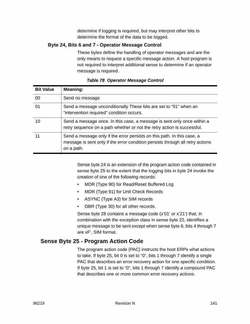
96219 Revision N 141
determine if logging is required, but may interpret other bits to determine the format of the data to be logged.
Byte 24, Bits 6 and 7 - Operator Message ControlThese bytes define the handling of operator messages and are the only means to request a specific message action. A host program is not required to interpret additional sense to determine if an operator message is required.
Sense byte 24 is an extension of the program action code contained in sense byte 25 to the extent that the logging bits in byte 24 invoke the creation of one of the following records:• MDR (Type 90) for Read/Reset Buffered Log• MDR (Type 91) for Unit Check Records• ASYNC (Type A3) for SIM records• OBR (Type 30) for all other records.Sense byte 28 contains a message code (x’01’ or x’21’) that, in combination with the exception class in sense byte 22, identifies a unique message to be sent except when sense byte 6, bits 4 through 7 are xF’, SIM format.
Sense Byte 25 - Program Action CodeThe program action code (PAC) instructs the host ERPs what actions to take. If byte 25, bit 0 is set to “0”, bits 1 through 7 identify a single PAC that describes an error recovery action for one specific condition. If byte 25, bit 1 is set to “0”, bits 1 through 7 identify a compound PAC that describes one or more common error recovery actions.
Table 78 Operator Message Control
Bit Value Meaning:
00 Send no message
01 Send a message unconditionally These bits are set to “01” when an “intervention required” condition occurs.
10 Send a message once. In this case, a message is sent only once within a retry sequence on a path whether or not the retry action is successful.
11 Send a message only if the error persists on this path. In this case, a message is sent only if the error condition persists through all retry actions on a path.

142 Revision N 96219
Single Program Action Codes
Additional single PACs have been defined for the 3990 that are used when dealing with errors or conditions associated with non synchronous ESCON operations which are not currently supported by the SVA.
Table 79 Single Program Action Codes
Bits 1-7 Value Meaning
00 No program action required; exit with no error indication.
01 A retry is not recommended; exit with a permanent error indication. This mode is invoked on a functional device failure which cannot be recovered on any path.
02 An intervention required condition has been detected on the reporting unit. Issue a message to the operator indicating intervention is required on the reporting device. Then queue the I/O request until an interrupt is received from the functional device indicating that it is ready.
03-0F Not used
10 The condition that caused the unit check to be presented is not related to the channel program that is being processed. After performing the logging and message action shown in sense byte 24, bits 4 through 7, restart the channel program.
11-1B Not used
1C During a channel program in PCI Fetch Mode, the subsystem did a retry action. The data transferred to the channel may not be valid. The user should take action if the data was accessed before the channel program finished.
1D-7F Not used
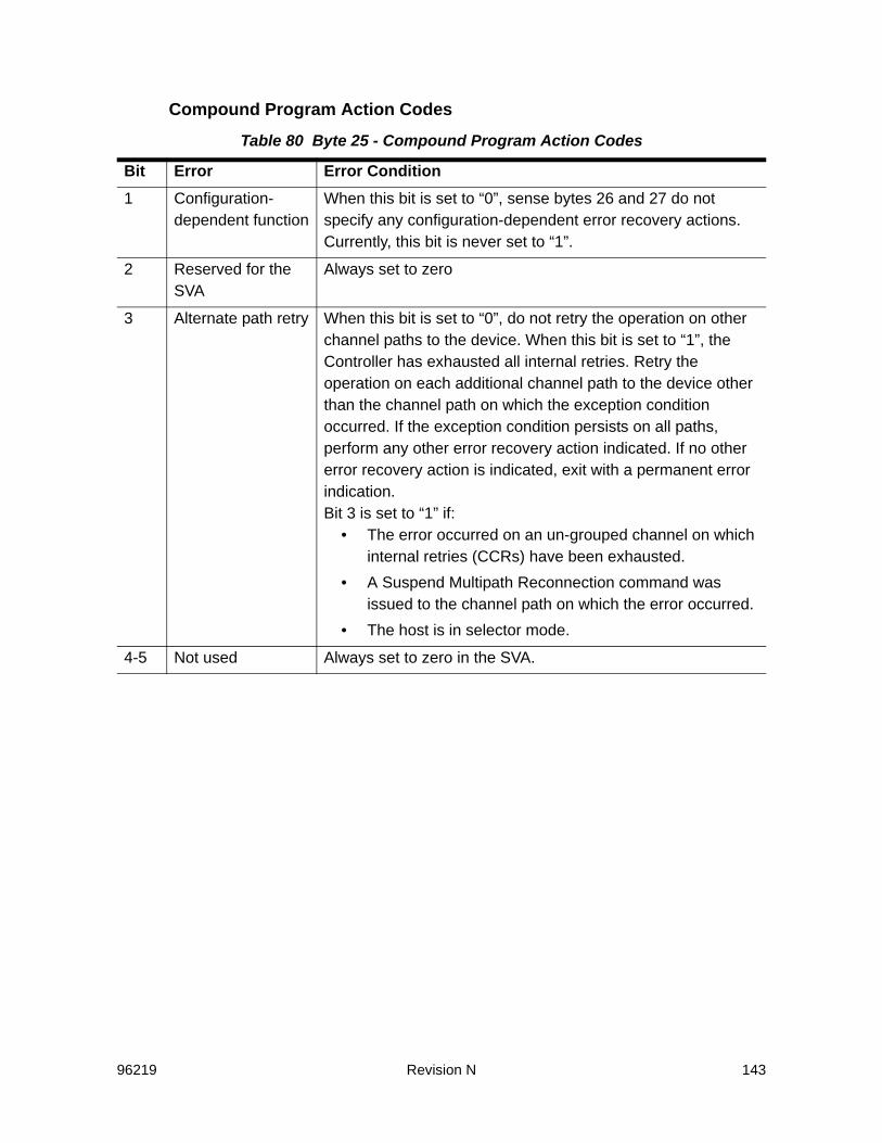
96219 Revision N 143
Compound Program Action Codes
Table 80 Byte 25 - Compound Program Action Codes
Bit Error Error Condition1 Configuration-
dependent functionWhen this bit is set to “0”, sense bytes 26 and 27 do not specify any configuration-dependent error recovery actions. Currently, this bit is never set to “1”.
2 Reserved for the SVA
Always set to zero
3 Alternate path retry When this bit is set to “0”, do not retry the operation on other channel paths to the device. When this bit is set to “1”, the Controller has exhausted all internal retries. Retry the operation on each additional channel path to the device other than the channel path on which the exception condition occurred. If the exception condition persists on all paths, perform any other error recovery action indicated. If no other error recovery action is indicated, exit with a permanent error indication. Bit 3 is set to “1” if:
• The error occurred on an un-grouped channel on which internal retries (CCRs) have been exhausted.
• A Suspend Multipath Reconnection command was issued to the channel path on which the error occurred.
• The host is in selector mode.
4-5 Not used Always set to zero in the SVA.

144 Revision N 96219
6-7 Retry Count Specifies the number of retries the host ERPs are to attempt using the same channel path on which the exception condition occurred. Bit Value Meaning00 Do not retry01 Retry twice10 Retry ten times11 Retry 255 times.If the exception condition persists and bit 3 is set to “0”, perform any other recovery action indicated. If no other error recovery action is indicated, exit with a permanent error indication.If the exception condition persists and bit 3 is set to “1”, attempt the operation on each additional channel path until the operation is completed successfully or until all channel paths have been tried. If the exception condition exists on all paths, perform any other error recovery action indicated. If no other action is indicated, exit with a permanent error condition.Bits 6 and 7 are always set to ’00’ for the Controller, unless the host is in selector mode or if the error occurred on an un-grouped channel on which internal retries have been exhausted.
Table 80 Byte 25 - Compound Program Action Codes (Continued)
Bit Error Error Condition

96219 Revision N 145
Sense Bytes 26 and 27 - Configuration DataSense Byte 26
Sense Byte 27
Table 81 Sense Byte 26 Bit Meaning
Bits Meaning
0 Reserved for the SVA and is always set to zero.
1 DLSE Mode. Always set to “1” for the SVA.
2-3 Reserved for the SVA and are always set to zeros.
4 Non synchronous operation. Set to “1” if a channel-connect operation.
5 Not used and is always set to zero.
6 Add the record to the system exception report. Set to “1” for exception class 6 and SIM sense data. This bit is not set in SIMs that report that a partition is low on conditional capacity.
7 Reserved for the SVA and is always set to zero.
Table 82 Sense Byte 27 Error Condition Data
Bit Error Error Condition0 24-byte
compatibilitySet to “0” if the sense data is ECKD 32-byte sense data. Set to “1” if the sense data is 24-byte compatibility sense data.
1-3 Reserved Always set to zero in the SVA
4 Reserved for the SVA
Always set to zero in the SVA
5 Reserved Always set to zero in the SVA
6 Storage cluster The storage cluster in use when the error was detected and/or reported. For exception class 4, B, C, D, and E SIMs, bit 6 is the reporting cluster. For non-SIM exception classes 4, 6, B, C, D, and E, bit 6 is not used and is always set to zero. For exception class 1, 2, 3, 7, and F SIMs (Controller SIMs), bit 6 is the storage cluster associated with the error or reporting the error.

146 Revision N 96219
Sense Byte 28 - Message Code or Bytes Read and SearchedThe information contained in this byte is dependent uponThe exception class of the sense data.• For exception class 6, this byte and sense bytes 29 through 31
contain the number of bytes read or searched. This is an accumulation byte count of all of the fields (including ECC) read from the device.
• For all other exception classes, this byte is reserved for the SVA and is always set to zero.
Sense Byte 29 - 31 - Track Address or Bytes Read and SearchedThe information contained in these bytes is dependent upon the exception class of the sense data.• For exception class 6, these bytes and byte 28 contain the
number of bytes read and searched. Refer to byte 28.• For non-SIM exception classes 4 and E, these bytes contain the
functional cylinder and head address (functional track address) of the most recent seek argument accepted from the channel since IML. If sense byte 6, bit 2 is set to “1”, the functional track address is valid. If sense byte 6, bit 2 is set to “0”, a functional track address cannot be associated with the error or condition and these bytes contain zeros.
7 Storage path The storage path in use when the error was detected. For exception classes 4, 6, B, C, D, and E, bit 7 is not used and is always set to zero. For exception classes 1, 2, 3, and F, bit 7 is the storage path associated with the error or reporting the error.
Table 82 Sense Byte 27 Error Condition Data
Bit Error Error Condition

96219 Revision N 147
Byte 29 - High Cylinder Address
Byte 30 - Low Cylinder Address
Byte 31 - Head Address
Table 83 High Cylinder Address
Bits Meaning
0-1 Not used (’00’)
2 Cylinder 8192
3 Cylinder 4096
4 Cylinder 2048
5 Cylinder 1024
6 Cylinder 512
7 Cylinder 256
Table 84 Low Cylinder Address
Bits Meaning
0 Cylinder 128
1 Cylinder 64
2 Cylinder 32
3 Cylinder 16
4 Cylinder 8
5 Cylinder 4
6 Cylinder 2
7 Cylinder 1
Table 85 Head Address
Bits Meaning
0-3 Not used (’0000’)
4 Head 8
5 Head 4
6 Head 2

148 Revision N 96219
ECKD 32-Byte Sense Exception ClassesECKD 32-byte sense data uses 12 exception classes to report error conditions associated with functional 3390 devices, non synchronous ESCON operations, and to report SIMs. Bits 0 through 3 of sense byte 22 contain the exception class of the error.
When byte 6, bits 4 through 7 are set to X’F’, the sense data is a SIM.
Exception Class 3 - Storage Path ChecksThe subsystem uses exception class 3 for errors or conditions associated with the storage path. These errors are reported to the host as a SIM only.
Exception Class 4 - Data ChecksThe subsystem uses exception class 4 to report data checks for functional devices configured as 3390-type devices. This exception class is only reported as format 1. Refer to the description for the Data
7 Head 1
Table 86 Exception Classes
Exception Class Category or Condition
Refer toPage:
0-2 Reserved for the SVA
3 Storage path checks (SIM only) 148
4 Data Checks 148
6 Subsystem information 149
7 Sun Microsystems support facility errors (SIM only) 149
B Controller-to-disk array interface errors (SIM only) 149
C Head-of-string (A-Disk Array Unit) errors (SIM only) 149
D Head-of-string-to-device interface errors (SIM only) 149
E Device errors 150
F Cache and NVS Checks 150
Table 85 Head Address
Bits Meaning
96219 Revision N 149
Check bit in sense byte 0 for the situations in which data checks can occur in an SVA.
Exception Class 6 - Subsystem InformationThe subsystem uses exception class 6 to report:• Functional device usage counts when the Controller receives a
Read and Reset Buffered Log command from the host. In this case, only the device usage counters are read and reset.
• That a functional device usage count requires off-loading because a counter overflowed. In this case, unit check is presented to a subsequent initial selection for that device, over any channel path. The sense data includes the usage count from the counter that overflowed.
• That a channel-interface’s data overrun count exceeded a threshold. When the interface’s counter exceeds the data overrun threshold, unit check is presented to a subsequent initial selection on that interface.
• Controller time-of-day. The time reported in bytes 10 through 13 is used to synchronize the Controller time with that of attached hosts. This sense data is reported once a day, around midnight, to each attached host. Usage counters are not reset, and the associated bytes are filled with zeros.
Exception Class 7 - Support Facility ErrorsThe subsystem uses exception class 7 to report support facility errors. These errors are reported to the host as a SIM only.
Exception Class B - Controller-to-Head-of-String Interface ErrorsThe subsystem uses exception class B to report errors that occur on the interface between the Controller and the head-of-string (HOS) A-Disk Array Unit. These errors are reported to the host as a SIM only.
Exception Class C - Head-of-String ErrorsThe subsystem uses exception class C to report errors that occur in the head-of-string (HOS) A-Disk Array Unit. These errors are reported to the host as a SIM only.
Exception Class D - Head-of-String to Device Interface ErrorsThe subsystem uses exception class D to report errors that occur on the interface between the HOS A-Disk Array Unit and a physical device. These errors are reported to the host as a SIM only.
150 Revision N 96219
Exception Class E - Device ErrorsThe subsystem uses non-SIM exception class E to report a functional device intervention required condition. For the SVA, such errors are only reported when:• An attempt was made to address a functional device that is
disabled (either by an operator or a host program)• There is a Controller-to-disk array communication failure• The subsystem is operating in data assurance check mode • An attempt was made to perform a write operation to a functional
device that is part of a Production or Test partition that is out of conditional capacity
An attempt was made to address an un-configured functional device.In all of the preceeding cases, Intervention Required (byte 0, bit 1) is set to “1”.The subsystem also uses exception class E to report physical device errors. These errors are reported to the host as a SIM only. For additional information on data assurance check mode, out of conditional capacity, and controller-to-disk array communication failure, refer to Appendix H, “Non-SIM Sense Data for Sun Microsystems Back-End Errors.”
Exception Class F - Cache and NVS ChecksThe subsystem uses exception class F to report SIMs related to cache and/or nonvolatile storage errors.

96219 Revision N 151
424-Byte Compatibility Sense Data
The SVA sense data consists of 32 bytes of information that identifies the cause of the last unit check status presented for a functional device on a channel interface. Sense data also contains information that may be required for system error recovery initiated by host error recovery procedures (ERPs).When sense byte 27, bit 0 is ‘1’, the sense data is formatted as 24-Byte Compatibility Sense. In this format, the first 24 bytes of the 32-byte sense data are compatible with the 24 bytes of sense data returned by pre-3990 subsystems.The SVA employs 24-byte compatibility sense data to report:• All Controller equipment checks• All program checks on all device addresses (format 0)• All equipment checks, data checks, and usage statistics for a
functional device configured as a 3380-type device.
Sense Byte Structure and MeaningThe SVA sends sense data to the channel when it receives a Sense command. If the Sense command is not preceded by a unit check status for the same device on the same channel interface, the sense data returned is format 0, message 0, with Bytes 0 through 3 equal to zero.In 24-byte compatibility sense data, the general exception condition is identified by the format and message found in sense Byte 7. Sense byte 7, bits 0 through 3 identify the format of the error message. Sense Byte 7, bits 4 through 7 specify the message that describes the exception condition. Host error recovery procedures are determined by the contents of sense bytes 0 through 2 (the unit check description bytes). Refer to “Sense Byte Structure and Meaning” on page 151.The Controller reports all specific back-end errors to the SVA support processor (ISP) in a failure report. The ISP logs the errors and generates service information messages (SIMs), as necessary. SIMs may identify a primary suspect field-replaceable unit (FRU) - the FRU
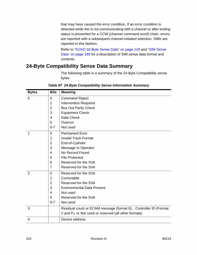
152 Revision N 96219
that may have caused the error condition. If an error condition is detected while the is not communicating with a channel or after ending status is presented for a CCW (channel command word) chain, errors are reported with a subsequent channel-initiated selection. SIMs are reported in this fashion.Refer to “ECKD 32-Byte Sense Data” on page 129 and “SIM Sense Data” on page 189 for a description of SIM sense data format and contents.
24-Byte Compatibility Sense Data SummaryThe following table is a summary of the 24-Byte Compatibility sense bytes.
Table 87 24-Byte Compatibility Sense Information Summary
Bytes Bits Meaning0 0
123456-7
Command RejectIntervention RequiredBus Out Parity CheckEquipment CheckData CheckOverrunNot used
1 01234567
Permanent ErrorInvalid Track FormatEnd-of-CylinderMessage to OperatorNo Record FoundFile ProtectedReserved for the SVAReserved for the SVA
2 0123456-7
Reserved for the SVACorrectableReserved for the SVAEnvironmental Data PresentNot usedReserved for the SVANot used
3 Residual count or ECAM message (format 0), Controller ID (Format 2 and F), or Not used or reserved (all other formats)
4 Device address

96219 Revision N 153
24-Byte Compatibility Sense Data DefinitionsThis section defines the contents of sense bytes reported in 24-byte compatibility sense data. Those bytes or bits that are defined for a 3990-3, but do not apply in an SVA subsystem, are “Reserved for the SVA”. Those bytes or bits that are reserved for a 3990-3 and the SVA, are “Reserved”.
Sense Bytes 0, 1, and 2 - Unit Check DescriptionThese bytes describe the type of exception condition experienced and identify the specific action to take for error recovery.Note: All devices referred to in this chapter are functional devices unless
they are otherwise specified as physical devices. All tracks referred to in this chapter are functional tracks unless they are otherwise specified as physical or array tracks.
Byte 0, Bit 0 - Command RejectThe following conditions cause a command reject exception:• A command or sequence of commands was not valid.
5 Data overrun (format 6) or Low cylinder address (all other formats)
6 Reserved for the SVA (format 6) or Head and high cylinder address (all other formats)
7 Format and Message
8-14 Format-dependent error informationSubsystem information
15-16 Manufacturer, product, and plant ID
17-19 Controller serial number
20-23 Format-dependent error informationSubsystem information
24 Not used
25 Program action code (PAC)
26-27 Configuration data
28 Time-of-day (format 6)Not used (all other formats)
29-31 Time-of-day (format 6)Cylinder and head address
Table 87 24-Byte Compatibility Sense Information Summary (Continued)
Bytes Bits Meaning
154 Revision N 96219
• An argument in a command was not valid or not complete. • A write command violated the file mask.• A command in a Locate Record or Locate Record Extended
domain did not conform to the operation parameter(s). • The operation parameter of a Locate Record or Locate Record
Extended command specified an operation that the file mask inhibits.
• A multitrack operation in a Locate Record or Locate Record Extended domain tried to access a track that is outside the primary track group.
• Cache, NVS, or the device was not in the state required for the Set Subsystem Mode or the Perform Subsystem Function command.
• A Write Data command in CKD conversion mode presented channel end and then found that the transfer length factor did not match the formatted record length. Invalid Track Format is also set to ‘1’.
• The subsystem detected an unauthorized modification of the subsystem configuration. Message to Operator is also set to ‘1’.
• A Write Special Home Address or Write Home Address command specified a write operation to a diagnostic, alternate, or device support cylinder, and the data being written did not indicate a normal error-free track with a standard HA.
• A Write Record Zero command specified a write operation to a diagnostic, alternate, or device support cylinder, and the data being written did not indicate a normal, error-free track with a standard record zero.
• A read command, other than Read Special Home Address, Read Home Address, or Read Record Zero, specified a read from a diagnostic, alternate, or device support cylinder.
• A Search HA command specified a search to a diagnostic, alternate, or device support cylinder.
• A write command was issued to a functional device that was in a logical ‘read-only’ state.
The unsupported 3990 commands and subcommands described in “Command Summary” on page 4-4 receive Command Reject in a the SVA subsystem.
Byte 0, Bit 1 - Intervention RequiredThe following conditions cause an intervention required exception:

96219 Revision N 155
• The addressed functional device was disabled.Note: A configured functional device can be logically enabled and disabled
via the ECAM software interface or from one of the subsystem operator panels.
• A write command was received for a functional device associated with a Production or Test partition and the partition was out of conditional capacity.
Note: An Erase command is rejected, since initially additional storage space is required to process the command.
• An SVA controller-to-disk array communication error occurred.• The subsystem is in Data Assurance Check (DAC) mode. Refer to
“Non-SIM Sense Data for Back-End Errors” on page 225.
Byte 0, Bit 2 - Bus Out Parity CheckA bus out parity check exception occurs if the Controller detected a data parity error during the transfer of information from the channel. A parity error that occurs during command transfer is a bus out parity check and not a command reject.
Byte 0, Bit 3 - Equipment CheckA data check exception occurs if an unusual hardware condition originated in the channel, Controller, disk array string, or Controller-to-disk array interface.
Byte 0, Bit 4 - Data CheckThe following conditions cause a data check exception:• If the PCI Fetch Mode was ‘1’ in the file mask and the data to the
channel was corrected by retry. Correctable (Byte 2, bit 1) is also set to ‘1’.
• If a functional track could not be staged because:- Drives within redundancy groups were removed or moved
without authorization - A triple drive failure occurred within a redundancy group - Secondary (redundancy grouping) tables were unrecoverable- Mapping tables were unrecoverable- Data was unreadable and unrecoverable (redundancy was
unreadable)In any of these cases, the fault symptom code indicates a home address area error. Permanent Error (Byte 1, Bit 0) is also set to ‘1’.
• If a functional track in cache was unreadable due to a cyclic redundancy check mismatch. The fault symptom code indicates a

156 Revision N 96219
key or data area error. Permanent Error (Byte 1, Bit 0) is also set to ‘1’.
• If a data error caused by a previous incomplete write operation was detected during a subsequent read operation. Permanent error (Byte 1, Bit 0) is also set to ‘1’
An incomplete write may occur if a processor failed during the write operation, and the write was not retried by the host following internal recovery for that processor failure.This data check does not occur if the host follows normal re-drive procedures. The fault symptom code (FSC) indicates a key or data area error.
Byte 0, Bit 5 - OverrunThe following condition causes:• An overrun exception occurs if a data overrun occurred during an
attempt to transfer data from the channel and the error could not be corrected after ten channel command retries. The sense data returned is format 2.
Byte 0, Bits 6 and 7These bits are not used by the SVA and are always set to zeros.
Byte 1, Bit 0 - Permanent ErrorThis is a modifier bit that overrides any other possible bit settings, and indicates that host program error recovery procedures are not required on this path.The following conditions cause a permanent error exception:• Internal retry was not applicable and no other path in either storage
cluster was available for retry Internal retry was not successful in either storage cluster System error recovery was not possible or not desirable on this path.
• If the operation is not associated with the current channel program, and internal retry was not successful, Environmental Data Present (Byte 2, Bit 3) is also set to ‘1’.
Byte 1, Bit 1 - Invalid Track FormatThe following conditions cause an invalid track format exception:• The host program tried to write data that exceeded the capacity of
a functional track. • The host program tried to perform an update write operation on a
record that had a different size than the record size parameter.

96219 Revision N 157
• The host program tried to perform a Write Track operation on a record zero data field that was not eight bytes in length.
• A track format error prevented the staging or de-staging of data. The sense data returned is format F, message 7.
Byte 1, Bit 2 - End of CylinderAn end of cylinder exception occurs if a read multitrack or search multitrack operation outside a Locate Record or Locate Record Extended domain tried to continue past the last track on the cylinder. This exception condition can be caused by a programming error or by an expected end-of-cylinder condition.
Byte 1, Bit 3 - Message to OperatorWhen set, this bit indicates that a message should be sent to the host operator.
Byte 1, Bit 4 - No Record FoundA no record found exception occurs if the specified record (record zero or a user record) could not be found on the track. This exception condition is usually caused by a programming error or an expected programming condition.
Byte 1, Bit 5 - File ProtectedThe following conditions cause a file protected exception:• A seek operation, Re-calibrate command, or a multitrack operation
outside a Locate Record or Locate Record Extended domain violated the seek controls of the file mask.
• An operation tried to access or operate on a track outside the boundaries established by a Define Extent command.
• A multitrack operation in a Locate Record or Locate Record Extended domain tried to access a track outside of the primary track group. Command Reject (Byte 0, Bit 0) is also set to ‘1’.
• A Re-calibrate command was received with diagnostic authorization specified in the file mask. This exception condition can be caused by a programming error or an expected programming condition.
Byte 1, Bits 6 and 7These bits are reserved for the SVA and are always set to zeros.
Byte 2, Bit 0This bit is reserved for the SVA and is always set to zero.

158 Revision N 96219
Byte 2, Bit 1 - CorrectableA correctable exception occurs if incorrect data was sent to the channel, and corrected data was resent. Data check (Byte 0, Bit 4) is also set to ‘1’. This exception condition occurs only if PCI Fetch Mode is active.
Byte 2, Bit 2This bit is reserved for the SVA and is always set to zero.
Byte 2, Bit 3 - Environmental Data PresentAn environmental data present exception occurs if the Controller has sense information to send to the host operating program, but the sense information is not associated with the current CCW string.
Byte 2, Bit 4This bit is not used and is always set to zero.
Byte 2, Bit 5This bit is reserved for the SVA and is always set to zero.
Byte 2, Bits 6 and 7These bits are not used and are always set to zeros.
Sense Byte 3 - Residual Count, ECAM Message ID, or Controller ID
The information contained in this byte is dependent upon the format of the sense data:• For format 0 with File Protected (byte 1, bit 5 set to ‘1’), this byte
contains the number of records remaining to be processed in the Locate Record or Locate Record Extended domain.
• For format 0 errors detected by the Controller ECAM code, this byte contains the ECAM message ID (the low byte of the fault symptom code).
• For formats 1, 2, and F, this byte contains the Controller ID, which is equal to the string ID, which is also the low byte of the subsystem ID.
• For all other formats, this byte is not used or reserved and is always set to zero.
Sense Bytes 4, 5, and 6Sense bytes 4, 5 and 6 identify the specific device address, the low-order and high-order cylinder address, and the head address of the

96219 Revision N 159
most recent seek argument from the channel for the current command chain.
Sense Byte 4 - Device AddressIf the storage path is reporting functional device status, this byte contains the functional device ID. If a functional device cannot be associated with the error, this byte contains zeros (refer to Byte 27, Bit 1).
Sense Byte 5 - Low-Order Cylinder AddressFor all formats except format 6, this byte contains the low-order cylinder address of the most recent seek argument from the channel. If the error was on an alternate track, this byte contains the low-order functional cylinder address of the defective track. Exception: if the sense data is for a 3390-9 device type, this byte contains the value 0xFF. The track address is in sense bytes 29-31. See the following table.
Table 88 Device Address
Bits Meaning0 Device Address 128
1 Device Address 64
2 Device Address 32
3 Device Address 16
4 Device Address 8
5 Device Address 4
6 Device Address 2
7 Device Address 1

160 Revision N 96219
If a seek argument has not been received since IML, this byte contains zeros. For format 6, this byte is reserved for the SVA and is always set to zero.
Sense Byte 6 - Head and High-Order Cylinder AddressFor all formats except format 6, this byte contains the high-order cylinder address (bits 0 through 3), and the head address (bits 4 through 7) of the most recent seek argument from the channel. If the error was on an alternate track, this byte contains the high-order functional cylinder address and the head address of the defective track. Exception: if the sense data is for a 3390-9 device type, this byte contains the value 0xFF. The track address is in sense bytes 29-31. If a seek argument has not been received since IML, this byte contains zeros.
Table 89 Low Order Cylinder Address Bits
Bits Meaning0 Cylinder Address 128
1 Cylinder Address 64
2 Cylinder Address 32
3 Cylinder Address 16
4 Cylinder Address 8
5 Cylinder Address 4
6 Cylinder Address 2
7 Cylinder Address 1
Table 90 High Order Cylinder Address Bits
Bits Meaning0 Cylinder address 2048
1 Cylinder address 1024
2 Cylinder address 512
3 Cylinder address 256
4 Head address 8
5 Head address 4
6 Head address 2

96219 Revision N 161
For format 6, this byte contains the data overrun flag, and is set to 0x01 when reporting that the data overrun threshold has been exceeded for this interface.
Sense Byte 7 - Format and MessageByte 7, bits 0 through 3 identify the format of an error message (refer to “24-Byte Compatibility Sense Formats Summary” on page 170), and Byte 7, Bits 4through 7 specify a message that describes the specific error condition (refer to “24-Byte Compatibility Sense Formats and Messages” on page 170). The exception condition being reported in Bits 4 through 7 depend on the sense format contained in Bits 0 through 3. For those formats that have no defined messages, their value is zero.
Sense Byte 8 - Reason Code, Record ID, or Bytes Read/SearchedThe information contained in this byte is dependent upon the format of the sense data.• For format 0 message F, and format F messages 2, 6, 9, B, and
D, this byte contains a reason code that gives additional information on the error identified in sense byte 7. (Refer to “Reason Codes” on page 178.)
• For format 0 messages 0 through E (with Message to Operator, Byte 1, Bit 3 set to ‘0’), format 2 messages A through E, format 3 (all messages), and format F message 0, this byte is not used and is always set to zero.
• For format 0 (with Message to Operator, Byte 1, Bit 3 set to ‘1’), this byte is reserved for the SVA and is always set to zero.
• For formats 4 and 5, this byte and Bytes 9 through 12 contain the record ID from the count field of the record that experienced the exception condition.
• For format 6, this byte and Bytes 9 through 11 contain the number of bytes read or searched, which is an accumulated byte count of all the fields (including ECC) read for the functional device. (If the sense is for a Seek CCW counter overflow, Bytes 8 through 11 are zeros.)
7 Head address 1
Table 90 High Order Cylinder Address Bits
Bits Meaning
162 Revision N 96219
• For format 1 (all messages), format 2 message F, and format F messages 1, 3, 4, A, and C, this byte is reserved for the SVA and is always set to zero.
Sense Bytes 9 and 10The information contained in these bytes is dependent upon the format of the sense data.• For formats 0, 2, and 3, these bytes are not used and are always
set to zeros.• For format 1, these bytes are reserved for the SVA and are always
set to zeros.• For formats 4 and 5, these bytes and Bytes 8, 11, and 12 contain
the record ID (refer to “Sense Byte 8 - Reason Code, Record ID, or Bytes Read/Searched” on page 161).
• For format 6, these bytes and Bytes 8 and 11, contain the number of bytes read or searched (refer to “Sense Byte 8 - Reason Code, Record ID, or Bytes Read/Searched” on page 161).
• For format F messages 0, 2, 6, 9, B, and D, these bytes are not used and are always set to zeros.Exception: For format F message 0, when the fault symptom code is FFF1, these bytes contain the reason that the functional device is in a state-change pending condition. Refer to “Reason Codes for State-Change Pending Sense Data” on page 183.
• For format F, message 1, these bytes are reserved for the SVA and are always set to zeros.
Sense Byte 11The information contained in this byte is dependent upon the format of the sense data.• For formats 4 and 5, this byte and Bytes 8 through 10, and 12
contain the record ID (refer to “Sense Byte 8 - Reason Code, Record ID, or Bytes Read/Searched” on page 161).
• For format 6, this byte and Bytes 8 through 10 contain the number of bytes read or searched (refer to “Sense Byte 8 - Reason Code, Record ID, or Bytes Read/Searched” on page 161).
• For format 1, this byte is reserved and is always set to zero.• For formats 0, 2, 3, and F, this byte and sense Byte 12 contain the
Cluster/Path/ Hardware Level ID, which identifies the cluster and path on which the error condition occurred; the number of installed
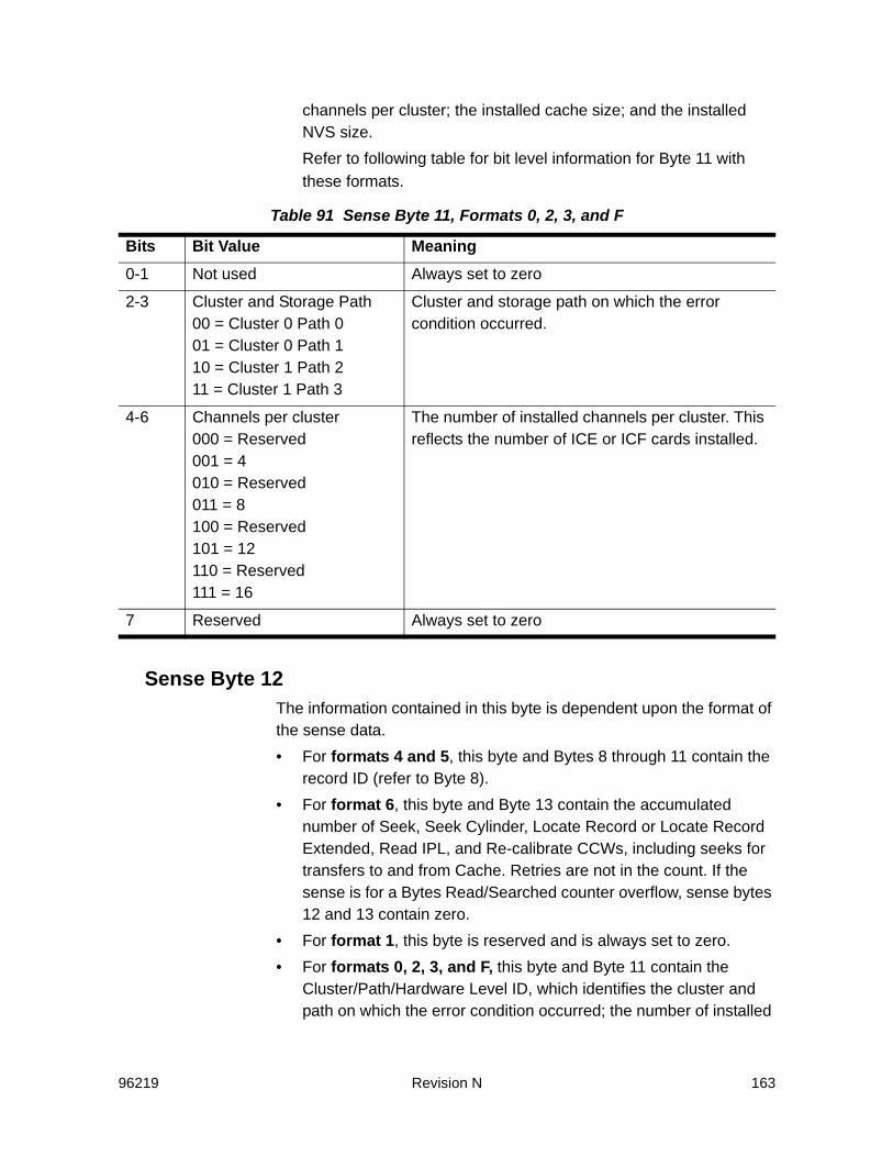
96219 Revision N 163
channels per cluster; the installed cache size; and the installed NVS size.Refer to following table for bit level information for Byte 11 with these formats.
Sense Byte 12The information contained in this byte is dependent upon the format of the sense data.• For formats 4 and 5, this byte and Bytes 8 through 11 contain the
record ID (refer to Byte 8). • For format 6, this byte and Byte 13 contain the accumulated
number of Seek, Seek Cylinder, Locate Record or Locate Record Extended, Read IPL, and Re-calibrate CCWs, including seeks for transfers to and from Cache. Retries are not in the count. If the sense is for a Bytes Read/Searched counter overflow, sense bytes 12 and 13 contain zero.
• For format 1, this byte is reserved and is always set to zero.• For formats 0, 2, 3, and F, this byte and Byte 11 contain the
Cluster/Path/Hardware Level ID, which identifies the cluster and path on which the error condition occurred; the number of installed
Table 91 Sense Byte 11, Formats 0, 2, 3, and F
Bits Bit Value Meaning0-1 Not used Always set to zero
2-3 Cluster and Storage Path00 = Cluster 0 Path 001 = Cluster 0 Path 110 = Cluster 1 Path 211 = Cluster 1 Path 3
Cluster and storage path on which the error condition occurred.
4-6 Channels per cluster000 = Reserved001 = 4010 = Reserved011 = 8100 = Reserved101 = 12110 = Reserved111 = 16
The number of installed channels per cluster. This reflects the number of ICE or ICF cards installed.
7 Reserved Always set to zero
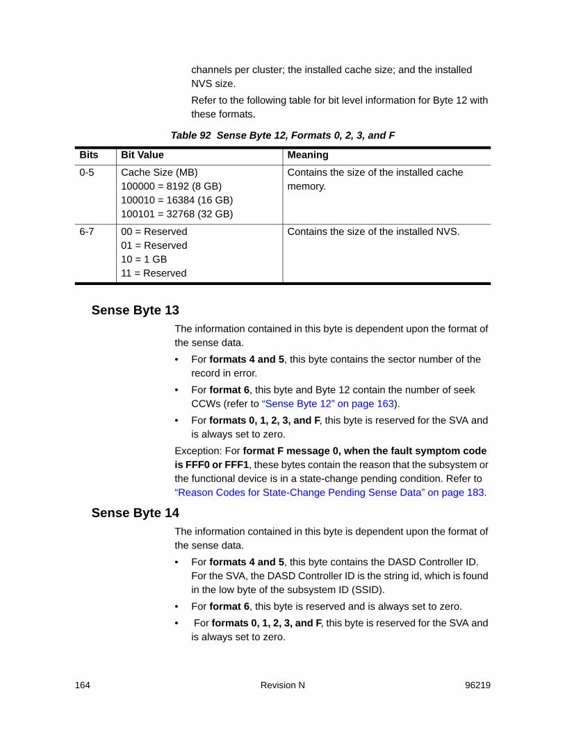
164 Revision N 96219
channels per cluster; the installed cache size; and the installed NVS size.Refer to the following table for bit level information for Byte 12 with these formats.
Sense Byte 13The information contained in this byte is dependent upon the format of the sense data.• For formats 4 and 5, this byte contains the sector number of the
record in error.• For format 6, this byte and Byte 12 contain the number of seek
CCWs (refer to “Sense Byte 12” on page 163).• For formats 0, 1, 2, 3, and F, this byte is reserved for the SVA and
is always set to zero.Exception: For format F message 0, when the fault symptom code is FFF0 or FFF1, these bytes contain the reason that the subsystem or the functional device is in a state-change pending condition. Refer to “Reason Codes for State-Change Pending Sense Data” on page 183.
Sense Byte 14The information contained in this byte is dependent upon the format of the sense data.• For formats 4 and 5, this byte contains the DASD Controller ID.
For the SVA, the DASD Controller ID is the string id, which is found in the low byte of the subsystem ID (SSID).
• For format 6, this byte is reserved and is always set to zero.• For formats 0, 1, 2, 3, and F, this byte is reserved for the SVA and
is always set to zero.
Table 92 Sense Byte 12, Formats 0, 2, 3, and F
Bits Bit Value Meaning0-5 Cache Size (MB)
100000 = 8192 (8 GB)100010 = 16384 (16 GB)100101 = 32768 (32 GB)
Contains the size of the installed cache memory.
6-7 00 = Reserved01 = Reserved10 = 1 GB11 = Reserved
Contains the size of the installed NVS.

96219 Revision N 165
Exception: For format F, message 0, when the fault symptom code is FFF0 or FFF1, these bytes contain the reason that the subsystem or functional device is in a state-change pending condition. Refer to “Reason Codes for State-Change Pending Sense Data” on page 183.
Sense Bytes 15 and 16 - Manufacturer, Product, and Plant IDThese bytes contain the manufacturer, product, and plant ID for the control unit reporting the sense data.
Sense Byte 15
Sense Byte 16
Sense Bytes 17 through 19 - Frame Serial NumberThese bytes contain the low three bytes of the frame serial number (converted to hexadecimal) for the Controller reporting the exception condition.
Sense Bytes 20 and 21 - SSIDThese bytes contain the SSID of the storage path affected by the exception condition. The information contained in these bytes is dependent upon the format of the sense data.
Table 93 Sense Byte 15
Bits Meaning0-5 Manufacturer ID (Sun Microsystems = 000100)
6-7 Product ID (high bits) (currently not used)
Table 94 Sense Byte 16
Bits Meaning0-2 Product ID (low bits)
Values currently defined:Reserved = 001Iceberg = 010
3 Reserved
4-7 Plant IDValues currently defined:
Louisville = 0001Puerto Rico = 0010
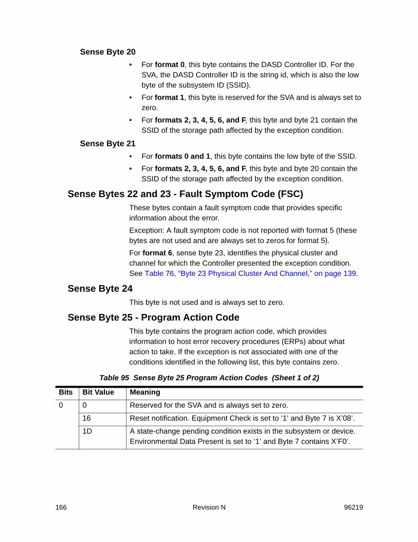
166 Revision N 96219
Sense Byte 20• For format 0, this byte contains the DASD Controller ID. For the
SVA, the DASD Controller ID is the string id, which is also the low byte of the subsystem ID (SSID).
• For format 1, this byte is reserved for the SVA and is always set to zero.
• For formats 2, 3, 4, 5, 6, and F, this byte and byte 21 contain the SSID of the storage path affected by the exception condition.
Sense Byte 21• For formats 0 and 1, this byte contains the low byte of the SSID.• For formats 2, 3, 4, 5, 6, and F, this byte and byte 20 contain the
SSID of the storage path affected by the exception condition.
Sense Bytes 22 and 23 - Fault Symptom Code (FSC)These bytes contain a fault symptom code that provides specific information about the error.Exception: A fault symptom code is not reported with format 5 (these bytes are not used and are always set to zeros for format 5).For format 6, sense byte 23, identifies the physical cluster and channel for which the Controller presented the exception condition. See Table 76, “Byte 23 Physical Cluster And Channel,” on page 139.
Sense Byte 24This byte is not used and is always set to zero.
Sense Byte 25 - Program Action CodeThis byte contains the program action code, which provides information to host error recovery procedures (ERPs) about what action to take. If the exception is not associated with one of the conditions identified in the following list, this byte contains zero.
Table 95 Sense Byte 25 Program Action Codes (Sheet 1 of 2)
Bits Bit Value Meaning0 0 Reserved for the SVA and is always set to zero.
16 Reset notification. Equipment Check is set to ‘1’ and Byte 7 is X’08’.
1D A state-change pending condition exists in the subsystem or device. Environmental Data Present is set to ‘1’ and Byte 7 contains X’F0’.
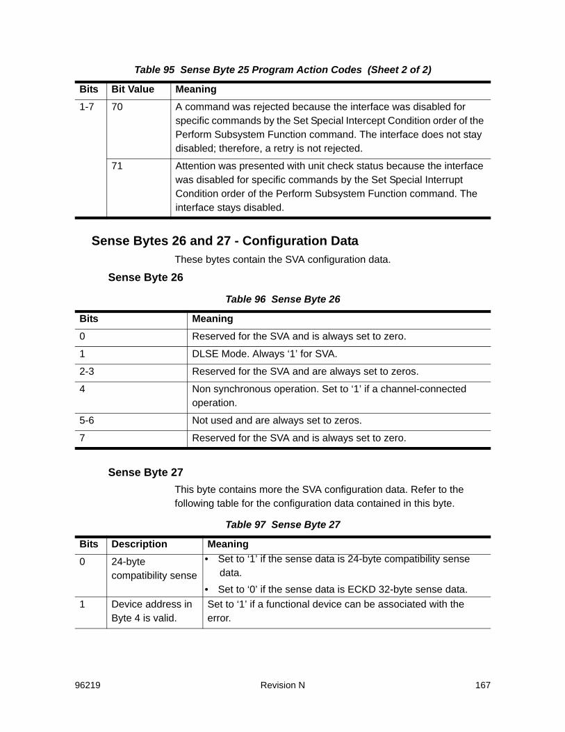
96219 Revision N 167
Sense Bytes 26 and 27 - Configuration DataThese bytes contain the SVA configuration data.
Sense Byte 26
Sense Byte 27This byte contains more the SVA configuration data. Refer to the following table for the configuration data contained in this byte.
1-7 70 A command was rejected because the interface was disabled for specific commands by the Set Special Intercept Condition order of the Perform Subsystem Function command. The interface does not stay disabled; therefore, a retry is not rejected.
71 Attention was presented with unit check status because the interface was disabled for specific commands by the Set Special Interrupt Condition order of the Perform Subsystem Function command. The interface stays disabled.
Table 96 Sense Byte 26
Bits Meaning0 Reserved for the SVA and is always set to zero.
1 DLSE Mode. Always ‘1’ for SVA.
2-3 Reserved for the SVA and are always set to zeros.
4 Non synchronous operation. Set to ‘1’ if a channel-connected operation.
5-6 Not used and are always set to zeros.
7 Reserved for the SVA and is always set to zero.
Table 97 Sense Byte 27
Bits Description Meaning0 24-byte
compatibility sense• Set to ‘1’ if the sense data is 24-byte compatibility sense
data.• Set to ‘0’ if the sense data is ECKD 32-byte sense data.
1 Device address in Byte 4 is valid.
Set to ‘1’ if a functional device can be associated with the error.
Table 95 Sense Byte 25 Program Action Codes (Sheet 2 of 2)
Bits Bit Value Meaning
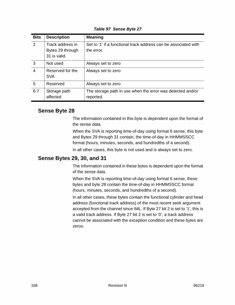
168 Revision N 96219
Sense Byte 28The information contained in this byte is dependent upon the format of the sense data.When the SVA is reporting time-of-day using format 6 sense, this byte and Bytes 29 through 31 contain, the time-of-day in HHMMSSCC format (hours, minutes, seconds, and hundredths of a second).In all other cases, this byte is not used and is always set to zero.
Sense Bytes 29, 30, and 31The information contained in these bytes is dependent upon the format of the sense data. When the SVA is reporting time-of-day using format 6 sense, these bytes and byte 28 contain the time-of-day in HHMMSSCC format (hours, minutes, seconds, and hundredths of a second). In all other cases, these bytes contain the functional cylinder and head address (functional track address) of the most recent seek argument accepted from the channel since IML. If Byte 27 bit 2 is set to ‘1’, this is a valid track address. If Byte 27 bit 2 is set to ‘0’, a track address cannot be associated with the exception condition and these bytes are zeros.
2 Track address in Bytes 29 through 31 is valid.
Set to ‘1’ if a functional track address can be associated with the error.
3 Not used Always set to zero
4 Reserved for the SVA
Always set to zero
5 Reserved Always set to zero
6-7 Storage path affected
The storage path in use when the error was detected and/or reported.
Table 97 Sense Byte 27
Bits Description Meaning

96219 Revision N 169
Byte 29 - High Cylinder Address
Byte 30 - Low Cylinder Address
Byte 31 - Head Address
Table 98 Sense Byte 29
Bits Meaning0-1 Not used (‘00’)
2 Cylinder 8192
3 Cylinder 4096
4 Cylinder 2048
5 Cylinder 1024
6 Cylinder 512
7 Cylinder 256
Table 99 Sense Byte 30
Bits Meaning0 Cylinder 128
1 Cylinder 64
2 Cylinder 32
3 Cylinder 16
4 Cylinder 8
5 Cylinder 4
6 Cylinder 2
7 Cylinder 1
Table 100 Sense Byte 31
Bits Meaning0-3 Not used (‘0000’)
4 Head 8
5 Head 4
6 Head 2
7 Head 1
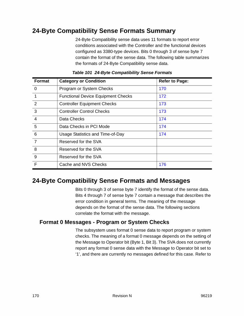
170 Revision N 96219
24-Byte Compatibility Sense Formats Summary24-Byte Compatibility sense data uses 11 formats to report error conditions associated with the Controller and the functional devices configured as 3380-type devices. Bits 0 through 3 of sense byte 7 contain the format of the sense data. The following table summarizes the formats of 24-Byte Compatibility sense data.
24-Byte Compatibility Sense Formats and MessagesBits 0 through 3 of sense byte 7 identify the format of the sense data. Bits 4 through 7 of sense byte 7 contain a message that describes the error condition in general terms. The meaning of the message depends on the format of the sense data. The following sections correlate the format with the message.
Format 0 Messages - Program or System ChecksThe subsystem uses format 0 sense data to report program or system checks. The meaning of a format 0 message depends on the setting of the Message to Operator bit (Byte 1, Bit 3). The SVA does not currently report any format 0 sense data with the Message to Operator bit set to ‘1’, and there are currently no messages defined for this case. Refer to
Table 101 24-Byte Compatibility Sense Formats
Format Category or Condition Refer to Page:0 Program or System Checks 170
1 Functional Device Equipment Checks 172
2 Controller Equipment Checks 173
3 Controller Control Checks 173
4 Data Checks 174
5 Data Checks in PCI Mode 174
6 Usage Statistics and Time-of-Day 174
7 Reserved for the SVA
8 Reserved for the SVA
9 Reserved for the SVA
F Cache and NVS Checks 176

96219 Revision N 171
the following table for a list of messages defined for format 0 sense data with the Message to Operator bit set to 0.
Table 102 Format 0 Messages - Program or System Checks
Hex Code Message Meaning0 No message No additional information is available, or a SVS
specific error or condition occurred. The program check is defined in sense bytes 0 through 2.
1 Invalid command The command in the CCW is not supported by the SVA.
2 Invalid command sequence Commands in the CCW chain are not in the correct sequence.
3 CCW count less than required
The byte count in the CCW is less than required.
4 Invalid parameter An input value for the command in the CCW is not valid.
5 Diagnostic or special command violates file mask
A command in the CCW is not allowed the access authorization specified by the file mask.
6 Not used
7 Channel returned with incorrect retry CCW
The command portion of the CCW returned after a command retry sequence does not match the command for which retry was signalled.
8 Reset notification A system reset (or its equivalent, e.g., a power on reset) was received on an interface. The unit check that causes this sense data to be generated is presented to the next channel initiated selection following the resetting event. For the first selection to the reset interface, the unit check description (Bytes 0 through 2) is Environmental Data Present and Equipment Check, and the program action code (sense byte 25) is X’16’. For the first selection of other devices on the reset interface, the unit check description is Equipment Check and the program action code (sense byte 25) is X’16’.
9 Reserved for the SVA

172 Revision N 96219
Format 1 Messages - Device Equipment ChecksThe subsystem uses format 1 sense data to report the following intervention-required conditions for functional devices:• An attempt to address a device that has been disabled by a
subsystem operator or host program • Controller-to-Disk Array communication failure data assurance
check mode • A write was attempted to a functional device that is part of a
production partition or a test set partition that is out of conditional capacity.
In all cases, INTERVENTION REQUIRED (Byte 0, Bit 1) is set to ‘1’.For additional information on data assurance check mode, out of conditional capacity and controller-to-disk array failure, refer to “Non-SIM Sense Data for Back-End Errors” on page 225.
A Not used
B Reserved for the SVA
C Installation check A device type specified in the configuration is not supported by the current microcode. This error is presented with Equipment Check and Permanent Error set to ‘1’.
D Not used
E Reserved for the SVA
F Status not as required The status of a subsystem component (cache, NVS, interface device, etc.) is not the status required for the requested operation.
Table 103 Format 1 Messages - Device Equipment Checks
Hex Code Message Meaning0 No message A functional device intervention required
condition
1 Reserved for the SVA
2 Not used
3-6 Reserved for the SVA
Table 102 Format 0 Messages - Program or System Checks (Continued)
Hex Code Message Meaning
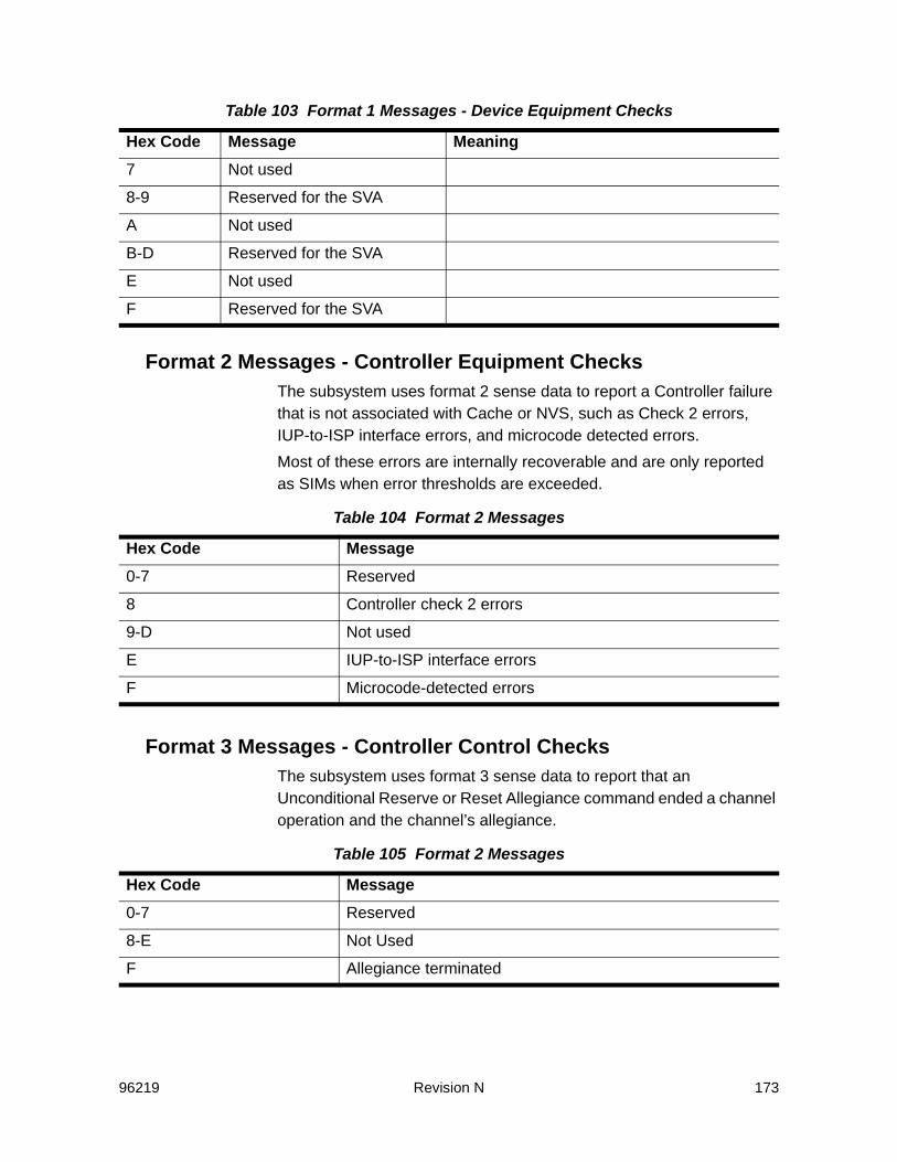
96219 Revision N 173
Format 2 Messages - Controller Equipment ChecksThe subsystem uses format 2 sense data to report a Controller failure that is not associated with Cache or NVS, such as Check 2 errors, IUP-to-ISP interface errors, and microcode detected errors.Most of these errors are internally recoverable and are only reported as SIMs when error thresholds are exceeded.
Format 3 Messages - Controller Control ChecksThe subsystem uses format 3 sense data to report that an Unconditional Reserve or Reset Allegiance command ended a channel operation and the channel’s allegiance.
7 Not used
8-9 Reserved for the SVA
A Not used
B-D Reserved for the SVA
E Not used
F Reserved for the SVA
Table 104 Format 2 Messages
Hex Code Message0-7 Reserved
8 Controller check 2 errors
9-D Not used
E IUP-to-ISP interface errors
F Microcode-detected errors
Table 105 Format 2 Messages
Hex Code Message0-7 Reserved
8-E Not Used
F Allegiance terminated
Table 103 Format 1 Messages - Device Equipment Checks
Hex Code Message Meaning

174 Revision N 96219
Format 4 Messages - Data ChecksThe subsystem uses format 4 sense data to report permanent data checks for functional devices configured as 3380-type devices. Refer to the description for the data check bit in sense byte 0 for the situations in which permanent data checks can occur within the subsystem.
Format 5 Messages - Data Checks in PCI ModeThe subsystem uses format 5 sense data to report that read data was corrected by the Controller using channel command retry (CCR) while the PCI fetch mode was active. A bit in the file mask byte activates the PCI fetch mode. If the PCI fetch mode is active, data transferred to the host may be processed by host programs before the final status is presented for the transfer (i.e. the host may have processed invalid data).
Format 6 Messages - Usage Statistics and Time-of-DayThe subsystem uses format 6 sense data to report:• Functional device usage counts when the Controller has received a
Read and Reset Buffered Log command from the host. When the Controller receives a Read and Reset Buffer Log command, only the device usage counters are read and reset.
Table 106 Format 4 Messages
Hex Code Message0 Home address area error
1 Reserved for the SVA
2 Key area error
3 Data area error
4-7 Reserved for the SVA
8-F Not used
Table 107 Format 5 Messages
Hex Code Message0-2 Reserved for the SVA
3 Data Check in the Data Area
4-F Not used

96219 Revision N 175
• That a functional device usage count needs to be off-loaded because a counter overflowed. When a device usage counter overflows, a unit check is presented to a subsequent initial selection for that device, over any channel path. The sense data includes the usage count from the counter that overflowed.
• That a channel-interface’s data overrun count exceeded a threshold. When the interface’s counter exceeds the data overrun threshold, unit check is presented to a subsequent initial selection on that interface.
• Controller time-of-day. The Controller time-of-day reported in Bytes 28 through 31 is used to synchronize the Controller time with that of the attached hosts. The time-of-day is reported daily (around midnight). Usage counters are not reset, and the associated bytes are filled with zeros.
The message for format 6 identifies the physical channel where the Controller presented the unit check. The same information is reported in the low nibble of the fault symptom code (FSC).
Table 108 Format 6 Messages
Hex Code Message Hex Code Message0 Channel A 8 Channel I
1 Channel B 9 Channel J
2 Channel C A Channel K
3 Channel D B Channel L
4 Channel E C Channel M
5 Channel F D Channel N
6 Channel G E Channel O
7 Channel H F Channel P

176 Revision N 96219
Format F Messages - Cache and NVS ChecksThe subsystem uses format F sense data to report errors associated with cache or nonvolatile storage.
Table 109 Format F Messages
Hex Code Message Meaning0 Operation
TerminatedThis message occurs when the subsystem rejects or terminates an operation related to an active channel program as a result of: • Re-initiating or terminating caching as the result of an error. • The storage path attempts to transfer a channel program to
another storage path using channel command retry, and determines that the channel is in selector mode.
• An emergency destage is required because of a fault in NVS.
• The subsystem or device is in a state-change pending condition. The request should be queued and re-driven by the host system. The subsystem signals the end of the state-change pending condition with a state-change interruption. Sense byte 25 contains X’1D’.
Sense data with this message causes attaching host to reissue the request. For a state-change pending condition, this sense record causes the host to queue and redrive the request on a periodic basis. Environmental Data Present is set to ‘1’.
1 Subsystem Processing Error
This message occurs when the microcode has detected a subsystem processing error in the internal control information for cache, or NVS.If the error is associated with the current channel program, Equipment Check is set to ‘1’. The error can cause caching to re-initiate.If the error was from an operation other than the current operation, Equipment Check and Environmental Data Present are set to ‘1’.

96219 Revision N 177
2 Cache or NVS Equipment Failure
Cache or NVS has an unrecoverable error.If the error is not recovered by the storage path’s internal recovery procedures, Equipment Check is set to ‘1’. If system retry is not desirable, Permanent Error and Equipment Check are set to ‘1’. Environmental Data Present is set to ‘0’ in either case. Permanent Error is set to ‘1’ with Environmental Data Present set to ‘0’, if the failure prevents successful ending of a command chain that must operate with cache. If the error was from an operation other than the current operation, Permanent Error and Environmental Data Present are set to ‘1’.
3-4 Reserved for the SVA
5 Not used
6 Cache Fast Write Access Not Authorized
This message occurs when a Define Extent command specifies cache fast write or a Perform Subsystem Function command has a Commit order, and the cache fast write ID in the command parameters is not the current cache fast write ID for the subsystem. Command Reject is set to ‘1’.
7 Reserved for the SVA
8 Not used
9 Caching Re-initiated
This message occurs when the storage director automatically reestablishes the caching function following a failure or condition.If the cause was a failure, another Equipment Check sense message defining the failure that caused the caching to re-initiate occurs with this sense message. The message occurs only if caching was active before the failure.Environmental Data Present is set to ‘1’ in either case.
A-C Reserved for the SVA
D Caching Status Reset to Default
Occurs when a storage path to shared memory error is detected.
Table 109 Format F Messages (Continued)
Hex Code Message Meaning

178 Revision N 96219
Reason CodesSense Byte 8 in 24-Byte Compatibility sense contains a reason code for certain Format/Message combinations. The reason code provides additional details on the cause of an error.Note: For the SVA, sense bytes 8-10, 9-10, and 13-14 may contain reason
codes for state-change pending (format F, message 0). Refer to “Reason Codes for State-Change Pending Sense Data” on page 183. for a description of these reason codes.
Reason Codes for Format 0 Message
E-F Not used
Table 110 Reason Codes For Format 0 Message F
Hex Code Message Meaning00 No Message Occurs in the following conditions:
• During the processing of a Diagnostic Control command with a Diagnostic Initialize Subsystem subcommand. The Controller determined that one or more of the devices in the functional storage control was not offline when the command was issued.
• The addressed functional device is in a read-only state.
01 Cache Status Pending
Trying to make cache available, and cache status is pending.
02-03 Reserved for the SVA
Always set to zero
04 Cache Fast Write Status Pending
Trying to activate cache fast write, and cache fast write status is pending.
05 Cache Status Pending
Trying to activate caching for a device, and cache status pending.
06 NVS Failure Trying to destage modified tracks, and the status of NVS is failed; or trying to discard DASD fast write data, and the data for the device exists in the failed NVS.
Table 109 Format F Messages (Continued)
Hex Code Message Meaning
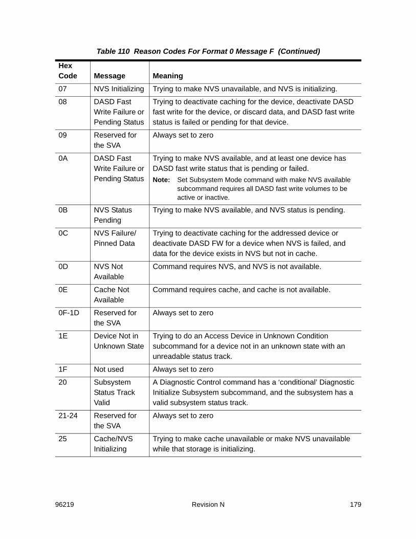
96219 Revision N 179
07 NVS Initializing Trying to make NVS unavailable, and NVS is initializing.
08 DASD Fast Write Failure or Pending Status
Trying to deactivate caching for the device, deactivate DASD fast write for the device, or discard data, and DASD fast write status is failed or pending for that device.
09 Reserved for the SVA
Always set to zero
0A DASD Fast Write Failure or Pending Status
Trying to make NVS available, and at least one device has DASD fast write status that is pending or failed. Note: Set Subsystem Mode command with make NVS available
subcommand requires all DASD fast write volumes to be active or inactive.
0B NVS Status Pending
Trying to make NVS available, and NVS status is pending.
0C NVS Failure/Pinned Data
Trying to deactivate caching for the addressed device or deactivate DASD FW for a device when NVS is failed, and data for the device exists in NVS but not in cache.
0D NVS Not Available
Command requires NVS, and NVS is not available.
0E Cache Not Available
Command requires cache, and cache is not available.
0F-1D Reserved for the SVA
Always set to zero
1E Device Not in Unknown State
Trying to do an Access Device in Unknown Condition subcommand for a device not in an unknown state with an unreadable status track.
1F Not used Always set to zero
20 Subsystem Status Track Valid
A Diagnostic Control command has a ‘conditional’ Diagnostic Initialize Subsystem subcommand, and the subsystem has a valid subsystem status track.
21-24 Reserved for the SVA
Always set to zero
25 Cache/NVS Initializing
Trying to make cache unavailable or make NVS unavailable while that storage is initializing.
Table 110 Reason Codes For Format 0 Message F (Continued)
Hex Code Message Meaning

180 Revision N 96219
26-28 Reserved for the SVA
Always set to zero
29 No Path Group for this Interface
Trying to do a Perform Subsystem Function command with the Set Special Intercept Condition order on an interface on which no path group has been established.
2A Not used Always set to zero
2B No Space In Message Buffer
Space in the message buffer cannot be made available.
2C-31 Reserved for the SVA
Always set to zero
2F Unsuccessful Reset Allegiance
A command was chained for a Reset Allegiance that was unsuccessful.
30 Not used Always set to zero
31 Reserved for the SVA
Always set to zero
32-34 Not used Always set to zero
35 Path is Fenced A Set Guaranteed Path subcommand of the Diagnostic Control was received for a fenced path.
3B-3F Reserved for the SVA
Always set to zero
41 Command Authorization Error
A command chain operating with normal authorization was received on a device that is in media maintenance reserve state.
42 Media Maintenance Query
Subcommand ErrorA Media Maintenance Query subcommand was received for a device that was in media maintenance reserve state.
43-7F Not used Always set to zero
80 Interface Disabled For Certain Commands
Trying to do a specific command on an interface that was disabled for specific commands by the Perform Subsystem Function command with the Set Special Intercept Condition order.
Table 110 Reason Codes For Format 0 Message F (Continued)
Hex Code Message Meaning
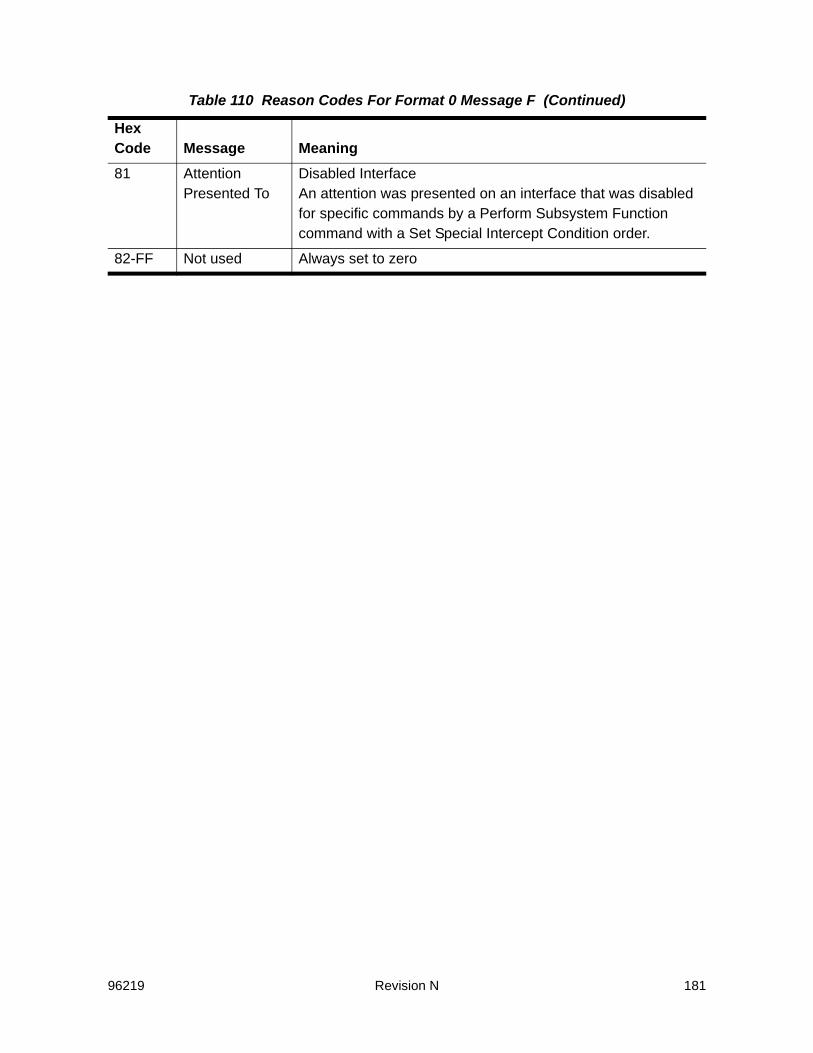
96219 Revision N 181
81 Attention Presented To
Disabled InterfaceAn attention was presented on an interface that was disabled for specific commands by a Perform Subsystem Function command with a Set Special Intercept Condition order.
82-FF Not used Always set to zero
Table 110 Reason Codes For Format 0 Message F (Continued)
Hex Code Message Meaning

182 Revision N 96219
Reason Codes for Format F, Message 2
Reason Codes for Format F, Message 6
Table 111 Reason Codes For Format F Message 2
Byte Bits Error/Operation Code8 0-3 0 Not used
1 Cache Control Check2 Reserved for the SVA3 Cache Port Register Check4 Cache Storage Check5 NVS Check6 Reserved for the SVA7 Not used8 Reserved for the SVA9 Not usedA Cache Power CheckB NVS Battery CheckC-E Not usedF Microcode Detected Error
8 4-7 0 No Operation1 Cache Directory Read2 Cache Directory Write3 Cache Read4 Cache Write5-8 Reserved for the SVA9 Not usedA NVS Directory ReadB NVS Directory WriteC NVS ReadD NVS WriteE-F Not used
Table 112 Reason Codes for Format F, Message 6
Hex Code Message00 Not used
01 Cache fast write ID is not the current ID
02 Reserved for the SVA
03-FF Not used
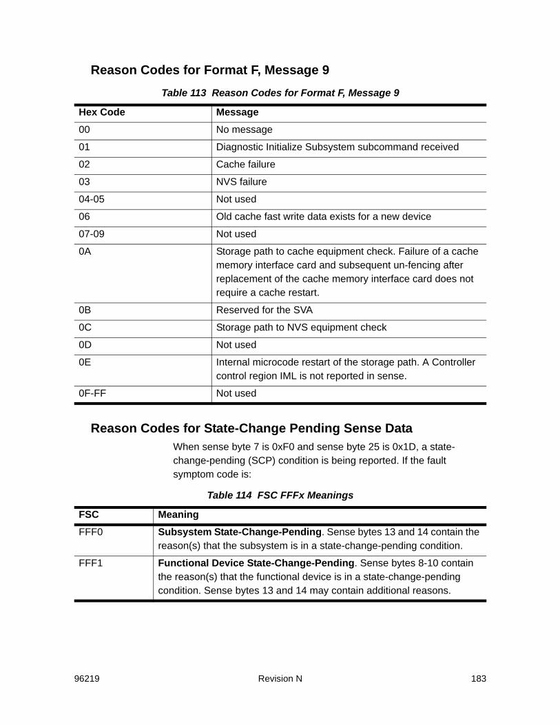
96219 Revision N 183
Reason Codes for Format F, Message 9
Reason Codes for State-Change Pending Sense DataWhen sense byte 7 is 0xF0 and sense byte 25 is 0x1D, a state-change-pending (SCP) condition is being reported. If the fault symptom code is:
Table 113 Reason Codes for Format F, Message 9
Hex Code Message00 No message
01 Diagnostic Initialize Subsystem subcommand received
02 Cache failure
03 NVS failure
04-05 Not used
06 Old cache fast write data exists for a new device
07-09 Not used
0A Storage path to cache equipment check. Failure of a cache memory interface card and subsequent un-fencing after replacement of the cache memory interface card does not require a cache restart.
0B Reserved for the SVA
0C Storage path to NVS equipment check
0D Not used
0E Internal microcode restart of the storage path. A Controller control region IML is not reported in sense.
0F-FF Not used
Table 114 FSC FFFx Meanings
FSC MeaningFFF0 Subsystem State-Change-Pending. Sense bytes 13 and 14 contain the
reason(s) that the subsystem is in a state-change-pending condition.
FFF1 Functional Device State-Change-Pending. Sense bytes 8-10 contain the reason(s) that the functional device is in a state-change-pending condition. Sense bytes 13 and 14 may contain additional reasons.

184 Revision N 96219
Sense Bytes 13 and 14 - Subsystem State-Change-Pending Reason Codes (FSC FFF0)
Sense Bytes 8-10 - Functional Device State-Change-Pending Reason Codes (FSC FFF1)
Table 115 State-Change-Pending Reason Codes
Bytes 13 - 14 Meaning0001 A warm start is in progress.
0002 Cache is being re initialized.
0008 Virtual Track Directory recovery in progress.
Table 116 Sense Bytes 8-10 Functional Device State-Change-Pending Reason Codes
Bytes 8 - 10 Meaning400000 An internal condition caused this PPRC primary device to be suspended.
Since the automation bit is set, the device is SCP for up to two minutes, starting at the time of the internal suspension, to allow system host automation code time to issue a Freeze PPRC Group order. The SCP condition is cancelled when a Freeze PPRC Group order is received for this device’s virtual control unit or after two minutes have expired.
200000 A Freeze PPRC Group order was received from a system host. Since the automation bit is set, all PPRC primary devices of the PCU that the Freeze order was issued to the SCP for up to two minutes, starting at the time the Freeze order was received, to allow system host automation code time to issue a PPRC Consistency Group Created order. The SCP condition is cancelled when the Consistency Group Created order is received or after two minutes have expired.
080000 A system host issued a selective or system reset during processing of a host write chain to this PPRC primary device. The device is SCP until all tracks related to this write have been transferred from the PCU to the SCU.
040000 If a CHK0 or cache re-init occurs when a host write to one or more PPRC primary devices in the subsystem is in progress, at the tail end of the warm start or cache re-init, all devices in the subsystem, other than PPRC secondary devices and PPRC data and status bridge devices, is SCP until the tracks associated with the host write have been transferred from this subsystem to the associated SCUs.
008000 A configuration change request is in progress.
004000 A partition change request is in progress.

96219 Revision N 185
002000 A Set Subsystem Mode operation with a Deactivate Cache for Addressed Device or a Deactivate DASD Fast Write for Device subcommand is in progress.
001000 An asynchronous Perform Subsystem Function operation with a Commit subcommand is in progress.
000800 A Diagnostic Control operation with a Diagnostic Initialize Subsystem subcommand is in progress for the functional storage control.
000400 A write was attempted to a track that is a target of a snapshot copy operation.
000100 Owed DE and chain time-out. An approaching chain time-out was detected following device busy presentation on another path group or selector mode channel.
000080 Chain time-out. An approaching chain time-out was detected.
000050 Disconnected device time-out. A disconnected device operation did not complete within an internal time-out period. The operation that is in progress, or the reason the operation has not been completed, is contained in sense bytes 13 and 14.
000048 Disconnected device time-out. One or more subsystem-level error conditions caused an internal time-out to occur. The error condition(s) that existed at the time the unit check was presented for the state-change pending condition are contained in sense bytes 13 and 14.
000042 Disconnected device time-out. Error recovery retry threshold exceeded. One of the SVA’s microprocessors has been overloaded with internal error recovery retries.
000041 Disconnected device time-out. No reason for the disconnection was found, but the reason has been resolved. This indicates that no disconnected device operation reason flags or subsystem-level error condition flags were set when the internal time-out monitor checked for them, but at least one of those flags had been set and cleared within the internal time-out period.
Table 116 Sense Bytes 8-10 Functional Device State-Change-Pending Reason Codes
Bytes 8 - 10 Meaning
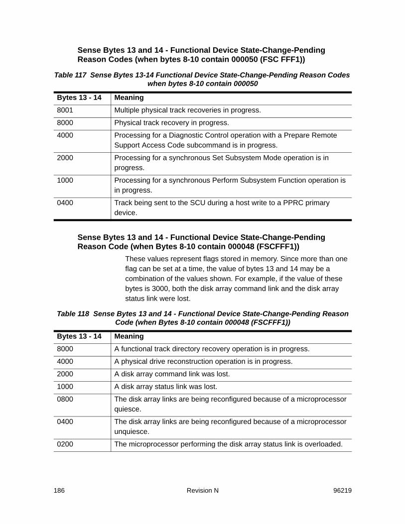
186 Revision N 96219
Sense Bytes 13 and 14 - Functional Device State-Change-Pending Reason Codes (when bytes 8-10 contain 000050 (FSC FFF1))
Sense Bytes 13 and 14 - Functional Device State-Change-Pending Reason Code (when Bytes 8-10 contain 000048 (FSCFFF1))
These values represent flags stored in memory. Since more than one flag can be set at a time, the value of bytes 13 and 14 may be a combination of the values shown. For example, if the value of these bytes is 3000, both the disk array command link and the disk array status link were lost.
Table 117 Sense Bytes 13-14 Functional Device State-Change-Pending Reason Codes when bytes 8-10 contain 000050
Bytes 13 - 14 Meaning8001 Multiple physical track recoveries in progress.
8000 Physical track recovery in progress.
4000 Processing for a Diagnostic Control operation with a Prepare Remote Support Access Code subcommand is in progress.
2000 Processing for a synchronous Set Subsystem Mode operation is in progress.
1000 Processing for a synchronous Perform Subsystem Function operation is in progress.
0400 Track being sent to the SCU during a host write to a PPRC primary device.
Table 118 Sense Bytes 13 and 14 - Functional Device State-Change-Pending Reason Code (when Bytes 8-10 contain 000048 (FSCFFF1))
Bytes 13 - 14 Meaning8000 A functional track directory recovery operation is in progress.
4000 A physical drive reconstruction operation is in progress.
2000 A disk array command link was lost.
1000 A disk array status link was lost.
0800 The disk array links are being reconfigured because of a microprocessor quiesce.
0400 The disk array links are being reconfigured because of a microprocessor unquiesce.
0200 The microprocessor performing the disk array status link is overloaded.
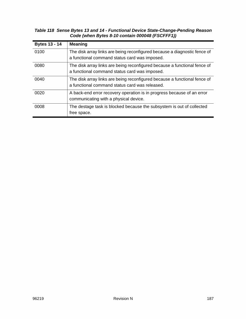
96219 Revision N 187
0100 The disk array links are being reconfigured because a diagnostic fence of a functional command status card was imposed.
0080 The disk array links are being reconfigured because a functional fence of a functional command status card was imposed.
0040 The disk array links are being reconfigured because a functional fence of a functional command status card was released.
0020 A back-end error recovery operation is in progress because of an error communicating with a physical device.
0008 The destage task is blocked because the subsystem is out of collected free space.
Table 118 Sense Bytes 13 and 14 - Functional Device State-Change-Pending Reason Code (when Bytes 8-10 contain 000048 (FSCFFF1))
Bytes 13 - 14 Meaning

188 Revision N 96219
96219 Revision N 189
5SIM Sense Data
Service Information Messages (SIMs) are a special class of ECKD 32-byte sense data. Many of the SIM bytes and bits have the same meaning as for ordinary sense data. These is not described in this chapter. Only the sense bytes and bits that are unique to SIM sense are described. The sense bytes and bits not described here are the same as those for non-SIM ECKD 32-Byte sense (refer to “ECKD 32-Byte Sense Data” on page 129).
SIM Sense Byte 1 - Unit Check DescriptionSIM Sense Byte 1, Bit 0 - Permanent Error: The following conditions cause a permanent error:• A failure report was sent to the support facility• Failure recovery was not possible or desirable for the failure.SIM Sense Byte 1, Bit 3 - Message to Operator: This bit is set when the subsystem determines that a failure (as specified in the following) is severe enough that an operator must be notified.• For Exception Classes 4, 6, B, C, D, and E, this bit is not used.• For Exception Classes 1, 2, 3, 7, and F, this bit is set to ‘1’ if:
- The SIM severity code (SIM sense byte 9, bits 0, 1) is greater than the severity reporting option parameter in the VPD
and:- SIM sense byte 28 is F1 (storage control failure), F2 (cache
failure), or FE (device failure)or:- SIM sense byte 28 is F3 (storage control failure - remote
access) and the code in SIM sense byte 8, bits 0-3 is ‘4’.In these conditions, if ServiceTek Plus attempts a remote connection, SIMs are generated to show that:- A connection is being attempted- Communication is not possible because SIM sense byte 8, bits
0-3 are set to ‘4’

190 Revision N 96219
- The operator is notified. (When Message to Operator is set to ‘1’, SIM sense byte 24, bits 6 and 7 are set to 01 to indicate Operator Message Unconditional.)
SIM Sense Byte 2 - Storage Control Type or Environmental Data Present
For Exception Classes 4, B, C, D, and E, SIM sense byte 2 contains an 8-bit code that identifies the storage control type, model, and features. For the SVA Controller, the only valid storage control type is X’06’.For Exception Classes 1, 2, 3, 7, and F, SIM sense byte 2 is reserved, except for bit 3, which is always set to indicate Environmental Data Present.
SIM Sense Byte 6 - Content and FormatFor Exception Classes 1, 2, 3, 7, and F, the value of SIM sense byte 6 is always X’8F’, which indicates that the serial number of the reporting unit in SIM sense bytes 15-19 is valid. The one exception to this rule is that certain FSCs of Exception Class 7 results in Bit 1 of Byte 6 being set. These are ECAM-related FSCs which indicates a device ID following the completion of a Mat or Drain Operation.For Exception Classes 4, B, C, D, and E (Device SIMs), this byte is the same as that of non-SIM ECKD sense.
SIM Sense Byte 7 - SIM Sense Record ID or Not UsedFor Exception Classes 1, 2, 3, 7, and F, this byte is always X’EO’.For Exception Classes 4, B, C, D, and E, this byte is not used and set to X’00’.
SIM Sense Byte 8 - Exception or Service Message CodesThe message contained in this byte depends on the SIM code defined for SIM sense byte 28. Valid SIM codes are F1, F2, F3, FE.Bits 0-3 of this byte contain the Exception Message, which lists the source of a failure. Bits 4-7 of this byte contain the Service Message, which indicates the effect of the repair.The following table summarizes the SIM codes, the Exception Messages, and the Service Messages.
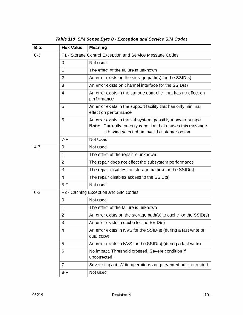
96219 Revision N 191
Table 119 SIM Sense Byte 8 - Exception and Service SIM Codes
Bits Hex Value Meaning0-3 F1 - Storage Control Exception and Service Message Codes
0 Not used
1 The effect of the failure is unknown
2 An error exists on the storage path(s) for the SSID(s)
3 An error exists on channel interface for the SSID(s)
4 An error exists in the storage controller that has no effect on performance
5 An error exists in the support facility that has only minimal effect on performance
6 An error exists in the subsystem, possibly a power outage.Note: Currently the only condition that causes this message
is having selected an invalid customer option.
7-F Not Used
4-7 0 Not used
1 The effect of the repair is unknown
2 The repair does not effect the subsystem performance
3 The repair disables the storage path(s) for the SSID(s)
4 The repair disables access to the SSID(s)
5-F Not used
0-3 F2 - Caching Exception and SIM Codes
0 Not used
1 The effect of the failure is unknown
2 An error exists on the storage path(s) to cache for the SSID(s)
3 An error exists in cache for the SSID(s)
4 An error exists in NVS for the SSID(s) (during a fast write or dual copy)
5 An error exists in NVS for the SSID(s) (during a fast write)
6 No impact. Threshold crossed. Severe condition if uncorrected.
7 Severe impact. Write operations are prevented until corrected.
8-F Not used
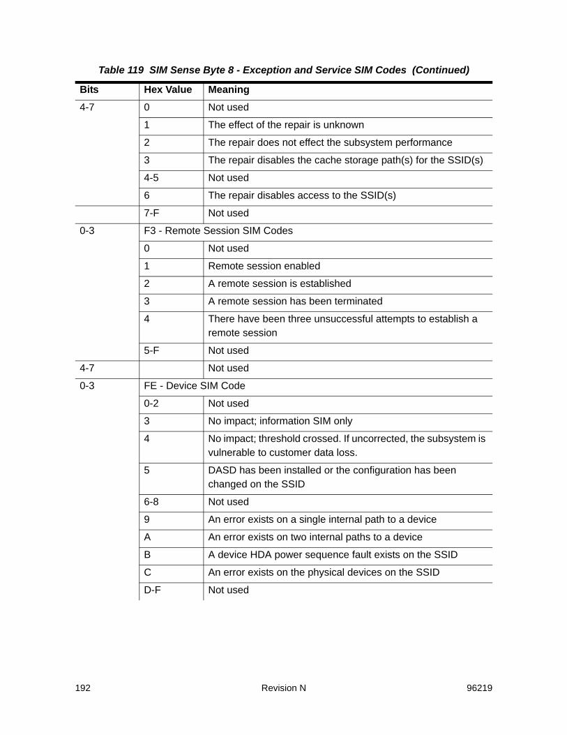
192 Revision N 96219
4-7 0 Not used
1 The effect of the repair is unknown
2 The repair does not effect the subsystem performance
3 The repair disables the cache storage path(s) for the SSID(s)
4-5 Not used
6 The repair disables access to the SSID(s)
7-F Not used
0-3 F3 - Remote Session SIM Codes
0 Not used
1 Remote session enabled
2 A remote session is established
3 A remote session has been terminated
4 There have been three unsuccessful attempts to establish a remote session
5-F Not used
4-7 Not used
0-3 FE - Device SIM Code
0-2 Not used
3 No impact; information SIM only
4 No impact; threshold crossed. If uncorrected, the subsystem is vulnerable to customer data loss.
5 DASD has been installed or the configuration has been changed on the SSID
6-8 Not used
9 An error exists on a single internal path to a device
A An error exists on two internal paths to a device
B A device HDA power sequence fault exists on the SSID
C An error exists on the physical devices on the SSID
D-F Not used
Table 119 SIM Sense Byte 8 - Exception and Service SIM Codes (Continued)
Bits Hex Value Meaning
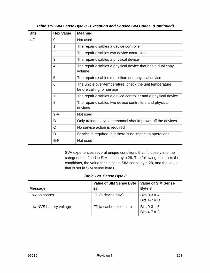
96219 Revision N 193
SVA experiences several unique conditions that fit loosely into the categories defined in SIM sense byte 28. The following table lists the conditions, the value that is set in SIM sense byte 28, and the value that is set in SIM sense byte 8.
4-7 0 Not used
1 The repair disables a device controller
2 The repair disables two device controllers
3 The repair disables a physical device
4 The repair disables a physical device that has a dual copy volume
5 The repair disables more than one physical device
6 The unit is over-temperature; check the unit temperature before calling for service
7 The repair disables a device controller and a physical device
8 The repair disables two device controllers and physical devices
9-A Not used
B Only trained service personnel should power off the devices
C No service action is required
D Service is required, but there is no impact to operations
E-F Not used
Table 120 Sense Byte 8
MessageValue of SIM Sense Byte 28
Value of SIM Sense Byte 8
Low on spares FE (a device SIM) Bits 0-3 = 4 Bits 4-7 = D
Low NVS battery voltage F2 (a cache exception) Bits 0-3 = 6 Bits 4-7 = 2
Table 119 SIM Sense Byte 8 - Exception and Service SIM Codes (Continued)
Bits Hex Value Meaning

194 Revision N 96219
Physical device failure: reconstruction started and physical device failure: reconstruction completed
FE (a device SIM) Bits 0-3 = C Bits 4-7 = C
Low on conditional capacity F2 (a caching exception) Bits 0-3 = 6 Bits 4-7 = 2
Media acceptance test completed and drain operation completed
FE (a device SIM) Bits 0-3 = 3 Bits 4-7 = C
Out of conditional capacity F2 in byte 28 a caching exception
Bits 0-3 = 7 Bits 4-7 = 2
Asynchronous processing error F2 in byte 28 a caching exception
Bits 0-3 = 1 Bits 4-7 = 1
Triple device failure FE in byte 28 a device SIM
Bits 0-3 = C Bits 4-7 = 5
Table 120 Sense Byte 8 (Continued)
MessageValue of SIM Sense Byte 28
Value of SIM Sense Byte 8

96219 Revision N 195
SIM Sense Bytes 9 and 10 - Message ModifiersSIM sense bytes 9 and 10 describe the severity of a failure, other information about the failure and the effect of repair. The specific codes depend on the value of SIM sense byte 28 (F1, F1, F3, or FE).
Table 121 SIM Sense Byte 9 - Message Modifier
Bit Error Condition (SIM Use)0-1 SIM
Severity Code
When the value of SIM sense byte 28 is F1, F2, or FE, the four defined meanings of bits 0 and 1 are:00 Service alert, but no impact to performance01 Moderate alert, but not an operational hit10 Serious alert that may cause an operational hit11 Acute alert with the potential to cause a loss of data when
the value of SIM sense byte 28 is F3 (indicating a remote session SIM), the four defined meanings of bits 0 and 1 are:
00 All remote session SIMs except “3 invalid attempts.”01 Not used10 Not used11 Three invalid attempts were made to connect from a
remote site.
2 Storage Path or Volume Affected
When the value of SIM sense byte 28 is F1, F2, or F3, the two defined meanings of bit 2 are:0 One storage path was affected by the failure1 Two or more storage paths were affected by the failureWhen the value of SIM sense byte 28 is FE, the two defined
meanings of bit 2 are:0 A primary volume was affected1 A secondary volume was affected
3 Storage Paths in the SSID
When the value of SIM sense byte 28 is F1, F2, or F3, the two defined meanings of bit 3 are:0 Two storage paths in the SSID1 Four storage paths in the SSIDIn SVA the value of SIM sense byte 9, bit 3 is always ’1’. When the value of SIM sense byte 28 is FE, this bit is not used and is set to ’0’.

196 Revision N 96219
SIM Sense Byte 11 - 14 - ECAM SIMsIf the fault symptom code (FSC) in SIM sense bytes 22-23 is 730C, 730D, 7328, or 7329 (“MAT or DRAIN Complete” SIMs), these bytes contain an ECAM process ID. Otherwise these bytes are as described in the following sections.
4-7 Dependent on Value of SIM Sense Byte 28
When the value of SIM sense byte 28 is FE, bits 4 and 5 indicate:• First device path number (0-3)• Second device path number (0-3)
When the value of SIM sense byte 28 is F1, F2, or F3, the two defined meanings of :hp2.bit 4:ehp2. are:0 One SSID is affected by the failure1 Two SSIDs are affected by the failureNote: In SVA the value of SIM sense byte 9, bit 4 is always ’0’.When the value of SIM sense byte 28 is F1, F2, or F3, the two defined meanings of bit 5 are:0 One SSID is affected by the repair1 Two SSIDs are affected by the repairNote: In SVA the value of SIM sense byte 9, bit 5 is always ’0’.When the value of SIM sense byte 28 is F1, F2, or F3, the two defined meanings of bit 6 are:0 Upgraded1 TerminatedWhen the value of SIM sense byte 28 is F1, F2, or F3, bit 7 is set to ’0’.
Table 122 SIM Sense Byte 10 - Message Modifier
Bit Error Condition (SIM Use)0 Repeated
SIMWhen this bit is set to ’1’, this SIM is a repeat of an earlier SIM. SIMs are reported twice at eight hour intervals.
1-7 Reserved Always set to ’0’ in SVA.
Table 121 SIM Sense Byte 9 - Message Modifier
Bit Error Condition (SIM Use)

96219 Revision N 197
SIM Sense Byte 11 - Same as Previous Error or Feature Code
SIM Sense Byte 12 - Available CacheThis byte, along with bits 5-7 of SIM sense byte 11, indicates the amount of cache available to the customer in 32 MB increments.
SIM Sense Byte 13 - Unit Address• For Exception Classes 1, 2, 3, 7, and F, the value of SIM sense
byte 13 is always “0”.• For Exception Classes 4, B, C, D, and E (Device SIMs), this byte
contains the physical device address of the defective physical device.
Table 123 SIM Sense Byte 11 - Same as Previous Error or Feature Code
Bit Error Condition (SIM Use)0 Reserved Always set to ’0’
1 Same as Previous Error
When this bit is set to ’1’, it indicates that a SIM for the same error was sent previously. The SVA uses this SIM to indicate the reoccurrence of a prior problem.
2-3 Control Region affected
If SIM sense byte 28 is F1, this bit indicated the affected control region.If SIM sense byte 28 is other than F1, this bit is ’0’
4-7 Model and Feature code
These bits contain the first four bits of the hardware model and feature code of the machine. The balance of the hardware model and feature code is contained in SIM sense byte 12. Bits 4 through 7 indicate the following:The two defined meanings of bit 4 are:0 Standard SVA subsystem1 Extended SVA subsystemBits 5 through 7 and SIM sense byte 12 indicate the installed customer cache size in 32 megabyte increments.

198 Revision N 96219
SIM Sense Byte 14 - Machine-Initiated Maintenance Information
Table 124 SIM Sense Byte 14 - Machine-Initiated Maintenance Information
Bit Error Condition (SIM Use)0 Sense Data from
the Control Region or ISP
If this bit is ’1’, the SIM was generated by the IUP. If this bit is ’0’, the SIM was generated by the support facility.Note: SIMs generated by IUPs (functional code) include:
• low on conditional capacity• out of conditional capacity• triple drive failure• the IUPs cannot communicate with the support
processors• asynchronous channel command processing error
1-3 Machine-Initiated Maintenance Category - 0, 1, or 2
The settings of these bits indicate the category of machine-initiated maintenance.000 Category 0 001 Category 1 010 Category 2 011 Category 3 100 Not used 101 Category 5 (CSC Installation and Operation off-load) 110 Category 6 (Trace and State Save off-load) 111 Category 7 (Customer Service Engineer test)
4-6 Machine-Initiated Maintenance Status
The settings of these bits indicate the status of machine-initiated maintenance. 001 The maintenance file is open 010 A service representative closed the maintenance file 011 The maintenance file is closed completely 100 The maintenance file is reopened 101 An engineering maintenance file; assistance is required 110 Not used 111 An informational SIM with no associated
machine-initiated maintenance.
7 Support Facility ID This bit indicates the identity of the “master” support facility that is creating the SIM

96219 Revision N 199
SIM Sense Byte 28 - SIM CodeThe SIM code defines the message to be sent when the operator message control (SIM sense byte 24, bits 6-7) is not zero.Note: The SIM code is set no matter what the value of the operator
message control is.
The following SIM codes are defined:10 Reserved for ESCONF1 Storage control and service representative SIMF2 Cache and service representative SIMF3 Storage control and remote session SIMFE Device and service representative SIMFF Not used
SIM Sense Bytes 29-31 - SIM ModifiersThe messages contained in these bytes are unique to SVA. Therefore, SIM sense byte 6, bit 2 is always set to “0”, so that they are not misinterpreted by IBM’s error recovery programs.For ECAM SIMs (FSCs 730C, 730D, 7328, or 7329), and informational SIMs (SIM sense byte 14 bits 4-6 =’111’), these bytes are always’0’. Otherwise, they have the following meaning:• SIM sense byte 29 and SIM sense byte 30, bits 0-3 contain the
machine-activated sequence number, which includes the composite failure event identifier (CFE-ID) for the error indicated by the SIM. The subsystem can then match the CFE-ID to the incident log, the FRU change events, and the machine-activated maintenance events. Together, these provide a history of the error for the customer service engineer.
• SIM sense byte 30, bits 4-7, and byte 31 contain the index value that identifies the primary suspect FRU. If the value is 0xFFF, there is no suspect FRU associated with the SIM.
Any FRU with an index value greater than 100 and less than 900 is located in the disk array string. In this case, the first digit of the three digit number indicates in which Disk Array Unit it resides. Therefore:• All FRUs with an index value between 100 and 199 are in the A-
Disk Array Unit• All FRUs with an index value between 200 and 299 are in the first
C-Disk Array Unit• All FRUs with an index value between 300 and 399 are in the B-
Disk Array Unit
200 Revision N 96219
• All FRUs with an index value between 400 and 499 are in the second C-Disk Array Unit.
96219 Revision N 201
6Host Error Recovery Procedures
Whenever possible, recovery actions are executed within an SVA subsystem, and host error recovery procedure (ERP) involvement is avoided in most cases until after the failing component has been isolated within the subsystem. However, in the following conditions, the SVA subsystem may require host ERP actions to their full extent:
1. Both data paths in a cluster are defective and there are no path groups established from which internal subsystem recovery could be invoked through a channel in the other cluster.
2. The circuit card processing the command chain is defective and no path group has been established with other channels. If another path is available, it must be tried through host error recovery procedures.
3. Host programming errors, file protect faults, etc. are conditions over which the subsystem has no control. Host ERP actions are invoked and the required action is taken to handle these errors.
Error Recovery Actions Supported for 24-Byte Compatibility Sense
ERP actions for 24-byte compatibility sense data are invoked based on the contents of sense bytes 0-2. The SVA supports 11 host error recovery processes. The following sections describe the error recovery action taken and the conditions within an SVA subsystem that invoke the action.
Error Recovery Action 11. If all alternate channel paths have not been tried, repeat the
operation on a different channel path.
2. If all alternate channel paths have been tried and byte 25, bits 0 and 1 are not ’11’, post the job with a permanent error.
3. If all alternate channel paths have been tried, byte 25 bits 0 and 1 cannot be ’11’.
The SVA invokes this recovery action in the following conditions:

202 Revision N 96219
• The three conditions described in the introduction of this chapter.• During a read operation when a previous write operation failed and
the host did not follow the recovery actions requested by the Controller following a Channel Command Retry or Disconnect In sequence
• When a Controller-to-disk array communication failure has made the back-end storage temporarily unavailable.
Error Recovery Action 2Exit with programming error or unusual condition indication.The SVA invokes this recovery action whenever a host programming type error exists.
Error Recovery Action 31. Repeat the operation once.
2. If the error is intervention required (byte 0, bit 1), issue a message to the operator indicating that intervention is required on the reporting device. Then queue the I/O request until an interrupt is received from the device indicating that the device has been made ready.
3. If the error condition continues, do Error Recovery Action 1.
The SVA invokes this recovery action in the following conditions:• When a condition requiring operator intervention is detected and
the addressed device is configured as a 3380-type device.• When a channel bus out parity error is detected for any type of
addressed device.
Error Recovery Action 41. If sense byte 25 is X’1D’, the functional storage control or device is
in a “state-change pending” condition. Re-drive the request when the subsystem presents a state-change interruption (the pending condition exists).
Note: If the host is timing I/O operations, the request may be re-driven at some period greater than 15 seconds. The subsystem continues to return state-change pending sense data while the operation is in progress.
2. Repeat the operation 256 times.
3. If the error condition continues, do Error Recovery Action 1.
The SVA invokes this recovery action in the following conditions:

96219 Revision N 203
• A state-change-pending• Reset notification• A virtual device usage overflow.• Conditions 1 and 2 described in the introduction of this chapter.
Error Recovery Action 51. If the ERP does not support reset notification, go to step 3.
2. If sense byte 7 is X’08’, the path group ID for this path has been reset, but not by a Set Path Group ID command. The host system must ensure that this device is still grouped as expected for this system before the current task is reissued.
3. If the chain has not been retried 10 times, repeat the command chain.
4. If the error condition continues after 10 retries, determine if the request inhibit write (byte 2, bit 0) was ‘0’ for all operations in the command chain. If it was ‘0’ for all operations in the command chain, go to step 4.
5. The ERP must issue a Diagnostic Control command with an Inhibit Write subcommand X’02’. The contents of the program action code (byte 25) defines the path to inhibit as follows:
A. If sense byte 25 is X’17’ or x’57’, set the subcommand modifier to X’20’ (Controller).
B. If sense byte 25 is X’18’ or x’58’, set the subcommand modifier to X’40’ (channel path).
C. If sense byte 25 is X’19’ or x’59’, set the subcommand modifier to X’80’ (storage director).
4. Do Error Recovery Action 1.
SVA invokes this recovery action in the following conditions:• The conditions described in the introduction of this chapter• If a path grouping has been affected by a system reset.
Error Recovery Action 6Return an indication to the application that the data has been corrected. (The application is operating in PCI fetch mode; thus the application must supply the restart recovery action.The SVA invokes this recovery action when the subsystem is operating in PCI mode and the addressed device is configured as a 3380-type
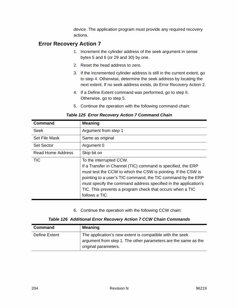
204 Revision N 96219
device. The application program must provide any required recovery actions.
Error Recovery Action 71. Increment the cylinder address of the seek argument in sense
bytes 5 and 6 (or 29 and 30) by one.
2. Reset the head address to zero.
3. If the incremented cylinder address is still in the current extent, go to step 4. Otherwise, determine the seek address by locating the next extent. If no seek address exists, do Error Recovery Action 2.
4. If a Define Extent command was performed, go to step 6. Otherwise, go to step 5.
5. Continue the operation with the following command chain:
6. Continue the operation with the following CCW chain:
Table 125 Error Recovery Action 7 Command Chain
Command MeaningSeek Argument from step 1
Set File Mask Same as original
Set Sector Argument 0
Read Home Address Skip bit on
TIC To the interrupted CCW. If a Transfer in Channel (TIC) command is specified, the ERP must test the CCW to which the CSW is pointing. If the CSW is pointing to a user’s TIC command, the TIC command by the ERP must specify the command address specified in the application’s TIC. This prevents a program check that occurs when a TIC follows a TIC.
Table 126 Additional Error Recovery Action 7 CCW Chain Commands
Command MeaningDefine Extent The application’s new extent is compatible with the seek
argument from step 1. The other parameters are the same as the original parameters.

96219 Revision N 205
7. Conditions:
The SVA invokes this recovery action when an end-of-cylinder is detected during a multitrack operation, which indicates a host programming type error.
Error Recovery Action 8This is a file protected error.
1. Examine the interrupted CCW to select the appropriate step in the following recovery actions.
2. If the interrupted CCW is a Perform Subsystem Function command, do Error Recovery Action 2.
3. If the interrupted CCW is not a Seek, Seek Cylinder, Seek Head, or Recalibrate command and the seek address is still in the current extent, go to step 4. (The seek address for a Recalibrate command is ‘0’.) Otherwise, determine the seek address by locating the next extent. If no seek address exists, do Error Recovery Action 2.
4. If a Define Extent command was performed, go to step 5. Otherwise, go to step 6.
Locate Record Bytes Contents 0 X’40’1-3 Zero4-7 The seek address from step 18-11 The seek address from step 112-15 Zero
TIC To the interrupted CCW.If a Transfer in Channel (TIC) command is specified, the ERP must test the CCW to which the CSW is pointing. If the CSW is pointing to a user’s TIC command, the TIC command by the ERP must specify the command address specified in the application’s TIC. This prevents a program check that occurs when a TIC follows a TIC.
Table 126 Additional Error Recovery Action 7 CCW Chain Commands (Continued)
Command Meaning

206 Revision N 96219
5. Continue the operation with the following CCW chain:
6. Continue the operation with the following CCW chain:
7. If the interrupted CCW was a Locate Record or Locate Record Extended command, determine if the seek address is in the application’s extents. If no seek address exists, do Error Recovery Action 2.
Table 127 Error Recovery Acton 8 CCW Chain
Command MeaningSeek Argument from step 3.
Set File Mask Same as the original
TIC The first non-TIC CCW following the interrupted CCW. If a Transfer in Channel (TIC) command is specified, the ERP must test the CCW to which the CSW is pointing. If the CSW is pointing to a user’s TIC command, the TIC command by the ERP must specify the command address specified in the application’s TIC. This prevents a program check that occurs when a TIC follows a TIC.
Table 128 Additional Error Recovery Acton 8 CCW Chains
Command MeaningSeek Argument from step 3.
Define Extent The application’s new extent is compatible with the seek argument from step 3. on page 205. The other parameters are the same as the original parameters.
TIC The first non-TIC CCW following the interrupted CCW.If a Transfer in Channel (TIC) command is specified, the ERP must test the CCW to which the CSW is pointing. If the CSW is pointing to a user’s TIC command, the TIC command by the ERP must specify the command address specified in the application’s TIC. This prevents a program check that occurs when a TIC follows a TIC.

96219 Revision N 207
8. Continue the operation with the following CCW chain:
9. This is either a multitrack CCW or the domain of a Locate Record or Locate Record Extended command has gone beyond the current extent. Therefore:
A. Increment the seek address in sense bytes 5 and 6 by one.
B. If the incremented seek address is still in the current application’s extent, go to step 9 C. Otherwise, determine the seek address by locating the next extent. If no seek address exists, do Error Recovery Action 2.
C. If a Define Extent command was performed, go to step 6. on page 208. Otherwise, continue with step 9 D.
D. Continue the operation with the following CCW chain:
Table 129 Additional Error Recovery Acton 8 CCW Chains
Command MeaningDefine Extent The application’s new extent is compatible with the seek
argument from step 3. on page 205. The other parameters are the same as the original parameters.
TIC The first non-TIC CCW following the interrupted CCW. If a Transfer in Channel (TIC) command is specified, the ERP must test the CCW to which the CSW is pointing. If the CSW is pointing to a user’s TIC command, the TIC command by the ERP must specify the command address specified in the application’s TIC. This prevents a program check that occurs when a TIC follows a TIC.
Table 130 Additional Error Recovery Acton 8 CCW Chains
Command MeaningSeek Argument from steps 9 A or 9 B.
Set File Mask Same as the original
Set Sector Argument 0
Read Home Address Skip bit on

208 Revision N 96219
E. If the modified seek argument is not in the application’s extent, IOS must supply the correct seek argument before doing a seek. If that is not possible, IOS must do Error Action 2.
6. Continue the operation with the following CCW chain:
TIC The first non-TIC CCW following the interrupted CCW.If a Transfer in Channel (TIC) command is specified, the ERP must test the CCW to which the CSW is pointing. If the CSW is pointing to a user’s TIC command, the TIC command by the ERP must specify the command address specified in the application’s TIC. This prevents a program check that occurs when a TIC follows a TIC.
Table 131 Additional Error Recovery Acton 8 CCW Chains
Command MeaningDefine Extent The application’s new extent is compatible with the seek
argument from steps 9 A. and 9 B. The other parameters are the same as the original parameters.
Table 130 Additional Error Recovery Acton 8 CCW Chains
Command Meaning
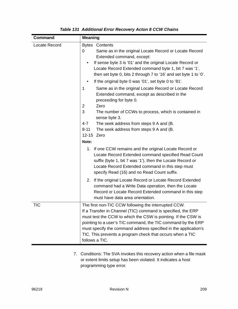
96219 Revision N 209
7. Conditions: The SVA invokes this recovery action when a file mask or extent limits setup has been violated. It indicates a host programming type error.
Locate Record Bytes Contents0 Same as in the original Locate Record or Locate Record
Extended command, except:• If sense byte 3 is ’01’ and the original Locate Record or
Locate Record Extended command byte 1, bit 7 was ’1’, then set byte 0, bits 2 through 7 to ’16’ and set byte 1 to ’0’.
• If the original byte 0 was ’01’, set byte 0 to ’81’.1 Same as in the original Locate Record or Locate Record
Extended command, except as described in the preceeding for byte 0.
2 Zero3 The number of CCWs to process, which is contained in
sense byte 3.4-7 The seek address from steps 9 A and (B.8-11 The seek address from steps 9 A and (B.12-15 ZeroNote:
1. If one CCW remains and the original Locate Record or Locate Record Extended command specified Read Count suffix (byte 1, bit 7 was ’1’), then the Locate Record or Locate Record Extended command in this step must specify Read (16) and no Read Count suffix.
2. If the original Locate Record or Locate Record Extended command had a Write Data operation, then the Locate Record or Locate Record Extended command in this step must have data area orientation.
TIC The first non-TIC CCW following the interrupted CCW.If a Transfer in Channel (TIC) command is specified, the ERP must test the CCW to which the CSW is pointing. If the CSW is pointing to a user’s TIC command, the TIC command by the ERP must specify the command address specified in the application’s TIC. This prevents a program check that occurs when a TIC follows a TIC.
Table 131 Additional Error Recovery Acton 8 CCW Chains
Command Meaning

210 Revision N 96219
Error Recovery Action 91. Present an operation message showing the path is write-inhibited,
the functional device address, and the path.
2. Vary the path to the device offline. Present a console message showing the functional device address, the path, and what path has been varied offline.
3. If any alternate path to the device is available, repeat the operation using an alternate path; otherwise, do Error Recovery Action 1.
The SVA subsystem does not invoke this recovery action. In a 3990-3 subsystem, this recovery action is invoked when a data path to a device has been previously write inhibited by an Inhibit Write subcommand of a Diagnostic Control command. This subcommand is processed as a No-Operation by SVA.
Error Recovery Action 10A specific command was rejected because the interface was disabled for the specific command by the Set Special Intercept Condition order of the Perform Subsystem Function command. The interface on which the command was rejected is no longer disabled; therefore, a retry is not rejected. The recovery action is used as an operating system interception by VM; therefore, the recovery is operating-system dependent.The SVA invokes this recovery action when a command is rejected as specified by the Set Special Intercept condition order of a Perform Subsystem Function command.
Error Recovery Action 11Attention was presented with unit check status, because the interface was disabled for the specific command by the Set Special Intercept Condition order of the Perform Subsystem Function command. The interface on which the attention and unit check was presented is still disabled. The recovery action is used as an operating system interception by VM; therefore, the recovery is operating-system dependent.The SVA invokes this recovery action when Attention status is presented on an interface that was disabled by a Perform Subsystem Function command with the Set Special Intercept order.In summary, SVA supports all ERP Actions except ERP Action 9 for 24-byte compatibility sense. The specific recovery methods used for retrying the same or different paths are used less frequently in the SVA

96219 Revision N 211
Controller than they are in the IBM 3990. The SVA places more emphasis on internal subsystem recovery.
Error Recovery Actions Supported for ECKD 32-Byte SenseERP Actions for ECKD 32-byte sense data (SIMs and 3390 device sense) are invoked based on the contents of sense byte 25 - the program action code (PAC). If bit 0 (the high bit) of byte 25 is ’0’, the hex value in bits 1 through 7 specify a single PAC. If bit 0 is ’1’, the hex value in bits 1 through 7 specify a compound PAC.The SVA supports all single PACs defined for a 3990-3. The following sections describe the error recovery action taken and the conditions within the SVA subsystem that invoke the action.Release 1 of SVA does not use compound PACs in sense data.
Action 00No program action is required; exit with no error indication.The SVA invokes this recovery action when no program action is required. In an SVA subsystem, no conditions have been identified that generate this action.
Action 01Retry is not recommended. Exit with a permanent error indication.The SVA invokes this recovery action in the following conditions:• During a read operation when a previous write operation failed and
the host did not follow the recovery actions requested by the Controller following a Channel Command Retry or Disconnect In sequence.
• When a Controller-to-disk array communication error has made the back-end storage temporarily unavailable.
Action 02An intervention required condition has been detected on a reporting functional storage control.• Issue a message to the operator indicating that intervention is
required on the reporting device.• Queue the I/O request until an interrupt is received from the device
indicating that the device is ready.The SVA invokes this recovery action when a condition requiring operator intervention is detected and the addressed device is configured as a 3390-type device.

212 Revision N 96219
Action 10The condition that caused the unit check to be presented is not related to the channel program that is being processed.• Perform the logging and/or message action shown in sense byte
24, bits 4 through 7.• Restart the channel program.• If the exception condition persists after 255 retries, exit with a
permanent error condition.The SVA invokes this recovery action when reporting SIMs.
Action 1CDuring a channel program in PCI fetch mode, the subsystem did a retry action. The data transferred to the channel may not be valid. The user should take action if the data was accessed before the channel program completed.The SVA invokes this recovery action when the subsystem is operating in PCI mode and the addressed device is configured as a 3390-type device.

96219 Revision N 213
AChannel Commands and Parameter Information
The SVA supports all of the channel commands and the parameters of channel commands that are supported by the IBM 3990, except for those listed in “Command Summary” on page 33. The SVA differs from the 3990 in the following ways:• The SVA presents different status to the host than the 3990 does,
but only when the differences cannot be detected by a program running at the “370 instruction set” layer of the host system i.e., host channel hardware or microcode may detect a difference in status presentation, but the host operating system or application software does not.
• The SVA does not always present Control Unit Busy in the same circumstances that IBM 3990 does.
For comparison, refer to the IBM 3990 Storage Control Reference, GA32-0099.The following section provides a detailed description of how the SVA differs from the IBM 3390 in processing certain channel commands.
Write Special Home Address Command (X09)The SVA permits writes to the alternate cylinder and diagnostic cylinder when the data being written indicates a normal, error-free track with a standard home address. This is the same data content that the subsystem produces when it emulates reads from the home address of these tracks. If the data written to the home address is different from the data that would be returned when emulating reads, the command is rejected and unit check status (invalid parameter) is presented.No writes are permitted to the device support cylinders, and Write Special Home Address does not cause record zero to be erased.
Read Special Home Address Command (X0A)The SVA emulates reads to the alternate cylinder and diagnostic cylinder for the Read Special Home Address command. However, for
214 Revision N 96219
other read commands (except Read Home Address and Read Record Zero), the command is rejected and unit check status is presented.
Space Count Command (X0F)The SVA requires that the key length and data length Space Count parameters must match the key length and data length of the record on the track. If this is not the case, the command is rejected, and the sense data returned is format 0, message 0. If the parameters are truncated, the command is rejected, and the sense data returned is format 0, message 3 (incorrect parameter bytes received). In contrast, the 3990 would pad the missing parameter bytes.For the following chain, the SVA presents “invalid track format” on the Space Count.
SeekSide to the last record on the trackSpace Count (no record exists)Read Data
The the SVA presents “invalid track format” because there is no count field to compare to the key length and data length parameters; therefore, the Space Count cannot be processed. In contrast, the 3390 would accept the Space Count command and present “invalid track format” on the Read Data command.
Write Record Zero Command (X15)The SVA permits writes to the alternate cylinder and diagnostic cylinder when the data being written indicates a normal, error free track with a standard record zero. This is the same data content that the subsystem produces when it emulates reads from the record zero of these tracks. If the data written to the record zero is different from the data that would be returned when emulating reads, the command is rejected and unit check status (invalid parameter) is presented.
Read Record Zero Command (X16)The SVA emulates reads to a standard record zero of the alternate cylinder and diagnostic cylinder for the Read Record Zero command. However, for other read commands (except Read Special Home Address and Read Home Address), the command is rejected and unit check status is presented.
96219 Revision N 215
Write Home Address Command (X19)The SVA permits a write of standard home address to the alternate cylinder and diagnostic cylinder. Write Home Address does not cause record zero to be erased when directed to the alternate cylinder and diagnostic cylinder.
Read Home Address Command (X1A)The SVA emulates reads to the alternate cylinder and diagnostic cylinder for the Read Home Address command. However, for other read commands (except Read Special Home Address and Read Record Zero), the command is rejected and unit check status is presented.
Perform Subsystem Function Command With:Commit Order (X27/X10)
The SVA processes this command and order in the same way that the 3390 does, except that the asynchronous de-staging of the modified tracks is deferred.
Discard Order (X27/X11)The SVA processes this command and order in the same way that the 3390 does.
Establish Duplex Pair Order (X27/X12)The SVA does not support a Perform Subsystem Function command with this order. The command is rejected, unit check status (invalid parameter) is presented.
Terminate Duplex Pair Order (X27/X13)The SVA does not support a Perform Subsystem Function command with this order. The command is rejected, unit check status (invalid parameter) is presented.
Terminate Suspend Pair Order (X27/X14)The SVA does not support a Perform Subsystem Function command with this order. The command is rejected, unit check status (invalid parameter) is presented.
Direct I/O Order (X27/X16)The SVA does not support a Perform Subsystem Function command with this order. The command is rejected, unit check status (invalid parameter) is presented.

216 Revision N 96219
Prepare for Read Subsystem Data Order & Read Storage Path Status Suborder (X27/X18/X00)
The SVA processes this command and order in the same way that the 3390 does. However, because of architectural differences, the data returned as storage path status is not compatible with the data that the what the 3990 returns. The four bytes of data for each storage path includes the following information:1st Byte:
2nd and 3rd Bytes: Bit map of channels enabled in this cluster4th Byte: Reserved
Prepare for Read Subsystem Data Order & Read Statistics Suborder (X27 / X18 / X01)
The the SVA processes this command and order in the same way that the 3390 does.
Prepare for Read Subsystem Data Order & Read Current Cache Fast Write ID (X27 / X18 / X01)
The SVA processes this command and order in the same way that the 3390 does.
Prepare for Read Subsystem Data Order & Read Message (X27 /X18 / X03)
The SVA processes this command and order in the same way that the 3390 does.
Prepare for Read Subsystem Data Order & Read Un-synchronized Cylinders (X27 / X18 / X04)
The SVA does not support a Perform Subsystem Function command with a Prepare for Read Subsystem Data Order and this suborder. The command is rejected, unit check status (invalid parameter) is presented.
Bit 0 (MSB) -Storage Path Installed
Bit 1 -Device attaches through this path
Bit 2 -Storage Path disabled
Bit 3 -Device fenced from this storage path
Bits 4 - 7 -Channel ID (0 - F)

96219 Revision N 217
Prepare for Read Subsystem Data Order and a Read Pinned Tracks (X27 / X18 / X05)
Because the SVA does not experience pinned tracks, the subsystem responds with “no data pinned.”
Set Special Intercept Order (X27 / X1B)The SVA processes this command and order in the same way that the 3390 does.Perform Subsystem Function Command with a destage.
Modified Tracks Order (X27 / X19)The SVA processes this command and order in the same way that the 3390 does, except that the modified tracks are queued for deferred, asynchronous destage.
Search Home Address (X39)The SVA does not permit searches to the alternate cylinder or the diagnostic cylinder. The command is rejected and unit check status is presented.
Read Subsystem Data Order (X3E)The SVA processes this command and order in the same way that the 3390 does.
Locate Record (X47)The operation byte specifies the orientation that is to be established when a track access is complete (bits 0 and 1). It also specifies the operations to perform in the Locate Record domain (bits 2 through 7). The SVA only accepts the following operation byte values when directed to the alternate and diagnostic cylinders: • Index orientation and a Format Write operation (XC3)• Index orientation and a Read operation (XD6)• Home address orientation and a Format Write operation (X43)• Home address orientation and a Read Data operation (X46)• Home address orientation and a Read operation (X56)• Home address orientation and a Orient operation (X40).The SVA only accepts the following operation byte values when directed to the device support cylinders:• Index orientation and a Read operation (XD6)• Home address orientation and a Read Data operation (X46)

218 Revision N 96219
• Home address orientation and a Read operation (X56)• Home address orientation and a Orient operation (X40).
Read Message ID (X4E)The SVA processes this command in the same way that the 3390 does.
Sense Subsystem Status (X54)The following cache information may be returned:• The configure cache capacity or user cache is the amount of
customer cache in the subsystem.• The available cache capacity is the amount of unfenced cache that
is not customer cache and not cache required by the functional track directory (FTD). The FTD may consume up to 128 megabytes of cache; the actual size of the FTD is determined by the configuration of the functional devices, and is independent of the physical configuration of the subsystem.
• Pinned cache space is always set to zero.• Offline cache capacity is the amount of cache (in bytes) that is
unavailable to the storage director.• The sum of the available cache capacity and pinned cache space
is always less than or equal to the configured cache capacity.
Read Device Characteristics (X64)The SVA responds with the alternate cylinder and diagnostic cylinder as configured. In release 1 of the SVA, the Read Device Characteristics specifies that dual copy is not supported.
Diagnostic Write (X73)This command is rejected and unit check status (invalid command) is presented.
Set Subsystem Mode (X87/X0000)When the Set Subsystem Mode command specifies no cache operation, no cache fast write operation, no message, and no nonvolatile storage operation, this command is processed as a No-Operation command. The SVA processes a No-operation command in the same way that the 3390 does.
96219 Revision N 219
Set subsystem Mode With:Cache Control - Activate Device (X87/X2000)
When the Set Subsystem Mode command specifies an activate device operation, the SVA processes this command in the same way that the 3390 does.
Cache Control - Deactivate Device (X87/X4000)When the Set Subsystem Mode command specifies a deactivate device operation, the caching algorithms for the functional device tracks are modified to minimize their use of cache. Therefore, modified tracks are immediately queued for de-staging, and unmodified tracks are discarded as soon as the cache capacity that they occupy is needed to store other tracks. However, cache sequential, look-ahead algorithms are not affected, IBM dual copy groups are not suspended, but CacheGuard immunity for the least-recently used algorithm is suspended. Also, “cache inactive for the functional device” is returned in response to a Read Subsystem Status command.
Cache Control - Activate Subsystem (X87/X6000)The SVA processes this command with this operation in the same way that the 3390 does.
Cache Control - Deactivate Subsystem (X87/XA000)When cache is deactivated for the subsystem, the caching algorithms used for the functional devices that are addressed in the functional storage control are modified as to minimize their use of cache. Therefore, modified tracks are immediately queued for de-staging, and unmodified tracks are discarded as soon as the cache capacity that they occupy is needed to store other tracks. However, cache sequential, look-ahead algorithms are not affected, IBM dual copy groups are not suspended, but CacheGuard immunity for the least-recently used algorithm is suspended. Also, “cache inactive for the functional device” is returned in response to a Read Subsystem Status command. The Read Subsystem Data counters are zeroed for the functional devices that are addressed in functional storage control. Cache inactive for the subsystem is returned in response to a Read Subsystem Status command.
Cache Control - Force Deactivate Subsystem (X87/X9000)This command with this operation is rejected and unit check status (invalid parameter) is presented.

220 Revision N 96219
Cache Fast Write Control - Activate CFW for the Subsystem (X87/X0C00)
The SVA processes this command with this operation in the same way that the 3390 does.
Cache Fast Write Control - Deactivate CFW for the Subsystem (X87/X1000)
The SVA processes this command with this operation in the same way that the 3390 does.
Asynchronous Message Required (X87/X0100)The SVA processes this command with this operation in the same way that the 3390 does.
DASD Fast Write Control - Activate (X87/X0020)The SVA processes this command with this operation in the same way that the 3390 does.
DASD Fast Write Control - Deactivate (X87/X0040)This command with this operation cause the DASD fast write status to be reported as inactive in response to a Read Subsystem Status command, and modified tracks are queued for destage. However, DASD fast write status has no permanent effect on caching algorithms.
DASD Fast Write Control - Force Deactivate (X87/X0060)This command with this operation is rejected and unit check status (invalid parameter) is presented.
Nonvolatile Storage Control - Activate (X87/X0080)The SVA processes this command with this operation in the same way that the 3390 does.
Nonvolatile Storage Control - Deactivate (X87/X00A0)When nonvolatile storage is deactivated for the subsystem, the caching algorithms used for the functional devices that are addressed in the functional storage control are modified as to minimize their use of cache. Therefore, modified tracks are immediately queued for de-staging, and unmodified tracks are discarded as soon as the cache capacity that they occupy is needed to store other tracks. However, cache sequential, look-ahead algorithms are not affected, IBM dual copy groups are not suspended, but CacheGuard immunity for the least-recently used algorithm is suspended. NVS inactive for the
96219 Revision N 221
subsystem is returned in response to a Read Subsystem Status Command.Note: The NVS battery is only be disconnected in response to a controlled
power-down from the operator panel or the remote operator panel.
Diagnostic Sense/Read Preceded by a Diagnostic ControlLocate Data Checks (XC4/X01)
If this command is received in an invalid command chain, the command is rejected and unit check status (invalid command sequence) is presented. If this command is received in a valid command chain, the Diagnostic Sense/Read command is still rejected, because the Diagnostic Control/Locate Data Checks command is rejected and unit check status (invalid parameter) is presented.
Select Subsystem Data (XC4/X06)If this command is received in an invalid command chain, the command is rejected and unit check status (invalid command sequence) is presented. If this command is received in a valid command chain, the Diagnostic Sense/Read command is still rejected, because the Diagnostic Control/Select Subsystem Data command is rejected and unit check status (invalid parameter) is presented.
Read Remote Support Access Code (XC4/X0A)This command is processed through the SVA’s support processors.
Start Application (XC4/X07)If this command is received in an invalid command chain, the command is rejected and unit check status (invalid command sequence) is presented. If this command is received in a valid command chain, the Diagnostic Sense/Read command is still rejected, because the Diagnostic Control/Start Application command is rejected and unit check status (invalid parameter) is presented.
Diagnostic Control With:Locate Data Checks (XF3/X01)
This command with this operation is rejected and unit check status (invalid parameter) is presented.
Inhibit Write (XF3/X02)The SVA processes this command as a No-Operation command.

222 Revision N 96219
Set Guaranteed Path (XF3/X04)The SVA processes this command as a No-Operation command.
Select Subsystem Data (XF3/X06)This command with this operation is rejected and unit check status (invalid parameter) is presented.
Select Trace (XF3/X07)This command with this operation is rejected and unit check status (invalid parameter) is presented.
Enable Write (XF3/X07)The SVA processes this command as a No-Operation command.
3380 Track Compatibility Mode (XF3/X09)This command with this operation is rejected and unit check status (invalid parameter) is presented.
Read Remote Support Access Code (XF3/X0A)This command is processed through the SVA’s support processors.
Diagnostic Initialize Subsystem (XF3/X0B)Note: The SVA subsystem defaults are not the same as those for the 3390.
In the SVA, a Diagnostic Control command with the Diagnostic Initialize Subsystem subcommand is viewed as a functional storage control reset, and the subsystem defaults (cache available, NVS available, DFW active, device caching active, CFW active, dual copy simplex) are reestablished for the functional devices addressed by the functional storage control. In this case, modified tracks are immediately queued for de-staging, and unmodified tracks are discarded as soon as the cache capacity that they occupy is needed for other tracks. Also, CacheGuard is terminated for the functional storage control. The interface device ID and functional device ID for each channel interface are not reset, and path groupings of secondary members of duplex pairs is reset.Note: This command causes the entire subsystem to experience CU Busy
for a brief period, while the Controller verifies that the functional storage control being addressed by the command is not active.
Un-fence Storage Path (XF3/X0C)This command with this operation is rejected and unit check status (invalid parameter) is presented.
96219 Revision N 223
Start Application (XF3/X0D)This command with this operation is rejected and unit check status (invalid parameter) is presented.
Access Device in Unknown Condition (XF3/X0F)This command is processed as defined by IBM; this command with this operation is rejected and unit check status (status not as required) is presented.
Media Maintenance Reserve (XF3/X10)The SVA processes this command as a No-Operation command and presents channel end and device end.
Media Maintenance Release (XF3/X11)The SVA processes this command as a No-Operation command and presents channel end and device end.
Media Maintenance Query (XF3/X12)The SVA processes this command as a No-Operation command and presents channel end and device end.
Remote Service Access (XF3/X13)This command with this operation is rejected and unit check status (invalid parameter) is presented.
Read Configuration Data (XFA)The SVA processes this command with this operation in the same way that the 3390 does, but specific SVA information is substituted as required.
No-Operation CommandsCommands that are processed as “no-operation” commands use the minimum processing resources possible. Chaining requirements are verified.
Unit Check, Invalid CommandWhen the SVA rejects those commands that are accepted by the 3990-3, the subsystem returns format 0 sense data with a unique fault symptom code. Chaining requirements for invalid commands are not verified.
224 Revision N 96219
Unit Check, Invalid ParameterWhen the SVA rejects those parameters that are accepted by the 3990-3, the subsystem returns format 0 sense data with a unique fault symptom code. Chaining requirements for the SVA-specific, invalid commands are not verified.
SubcommandsIf at least one subcommand is accepted for a command, the command’s chaining requirements are verified, but chaining requirements unique to invalid subcommands and parameters for invalid subcommands are not verified.
Device Busy at End of ChainThe SVA can present device busy status when the same channel path or group presents a TIO or NOP command before the completion of end of chain processing by the Controller.
Orientation Error Reporting for Locate RecordThe SVA can present detectable orientation errors such as no record found and invalid track format when processing a Locate Record command, without waiting for a subsequent data transfer command. In some cases, the 3390 waits for a subsequent data transfer command before presenting this kind of error.
Incomplete Domain Error ReportingThe SVA does not check for or report Incomplete Domain Error, exception class 0, category 2.

96219 Revision N 225
BNon-SIM Sense Data for Back-End Errors
Non-SIM sense data for the SVA back-end errors is reported to the host only in the following cases:
1. Data is unreadable due to a permanent data check. Refer to the description for Format 4 or Exception Class 4 sense and the Data Check bit in sense byte 0 for the situations in which permanent data checks can occur with the SVA. A SIM may be generated by the support facility as a result of this error.
2. The control unit cannot communicate with a disk array unit. This can occur for the following reasons:
A. both fibre channel loops inoperable
B. fibre channel links plugged in wrong or not connected
C. disk array unit not powered up.
When a Controller-to-Disk Array Unit communication failure is detected, the subsystem rejects all channel commands that access data or that affect subsystem or device configuration, until communications have been re-established. Format 1 Msg 0 sense is reported if the addressed virtual device is configured as a 3380-type device, and ECKD 32-byte Exception Class E sense data is reported, if the addressed virtual device is configured as a 3390-type device. Functional code reports ALL other back-end specific errors to the support facility in a failure report. The support facility logs the errors and generates SIMs as necessary. The SIMs provide information regarding suspect FRUs that may have caused the error condition.
3. The subsystem has entered data assurance check mode. This occurs when certain mapping table exceptions are detected. When in this state, the subsystem rejects all channel commands that access data or that affect subsystem or device configuration, until the data assurance check mode has been cleared at a subsystem operator panel.
4. The addressed device is a member of a production partition that is out of conditional capacity. In this case, the subsystem rejects all
226 Revision N 96219
write commands until storage space has been freed up on the back-end. SIMs are also generated when the subsystem is out of or low on conditional capacity.

96219 Revision N 227
CStandard Device Characteristics
Table 132 3390 Device Characteristics
Bytes Description3390 Model 1
3390 Model 2
3390 Model 3
3390 Model 9
0-1 Storage control type 3990 3990 3990 3390
2 Storage Control Model
Mod 3 sync CC CC CC CC
Mod 3 nonsync EC EC EC EC
3-4 Device type 3390 3390 3390 3390
5 Device model 02 06 0A 0C
6-9 Storage Control and Device Facilities, Mod 3 (NVS)
D0 00 10 96(or D0 00 30 96 if PPRC is enabled)
D0 00 10 96(or D0 00 30 96 if PPRC is enabled)
D0 00 10 96(or D0 00 30 96 if PPRC is enabled)
D0 00 10 96(or D0 00 30 96 if PPRC is enabled)
10 Device class code 20 20 20 20
11 Device type code 26 27 24 32
12-13 Primary cylinders 0459 08B2 0D0B 2721
14-15 Tracks per cylinder 000F 000F 000F 000F
16 Number of sectors E0 E0 E0 E0
17-19 Track length 00E5A2 00E5A2 00E5A2 00E5A2
20-21 Length of HA and RO 0594 0594 0594 0594
22 Track capacity formula 02 02 02 02
23 Factor F1 22 22 22 22
24-25 Factor F2 or F2F3 a 1309 1309 1309 1309
26-27 Factor F3 or F4F5b 0674 0674 0674 0674
28-29 First alternate cylinder 0459 08B2 0D0B 2721
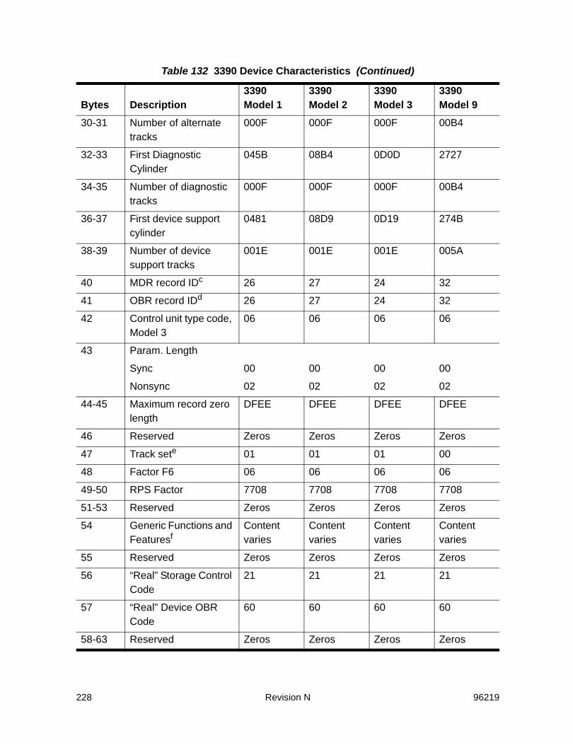
228 Revision N 96219
30-31 Number of alternate tracks
000F 000F 000F 00B4
32-33 First Diagnostic Cylinder
045B 08B4 0D0D 2727
34-35 Number of diagnostic tracks
000F 000F 000F 00B4
36-37 First device support cylinder
0481 08D9 0D19 274B
38-39 Number of device support tracks
001E 001E 001E 005A
40 MDR record IDc 26 27 24 32
41 OBR record IDd 26 27 24 32
42 Control unit type code, Model 3
06 06 06 06
43 Param. Length
Sync 00 00 00 00
Nonsync 02 02 02 02
44-45 Maximum record zero length
DFEE DFEE DFEE DFEE
46 Reserved Zeros Zeros Zeros Zeros
47 Track sete 01 01 01 00
48 Factor F6 06 06 06 06
49-50 RPS Factor 7708 7708 7708 7708
51-53 Reserved Zeros Zeros Zeros Zeros
54 Generic Functions and Featuresf
Content varies
Content varies
Content varies
Content varies
55 Reserved Zeros Zeros Zeros Zeros
56 “Real” Storage Control Code
21 21 21 21
57 “Real” Device OBR Code
60 60 60 60
58-63 Reserved Zeros Zeros Zeros Zeros
Table 132 3390 Device Characteristics (Continued)
Bytes Description3390 Model 1
3390 Model 2
3390 Model 3
3390 Model 9
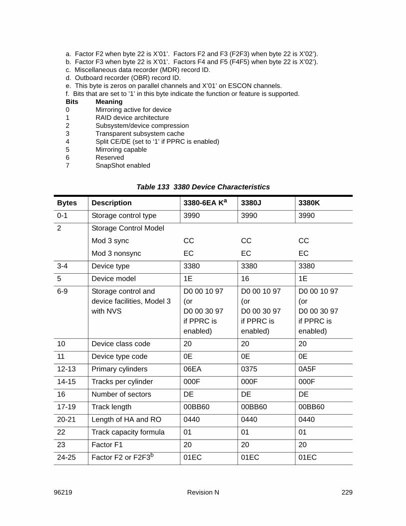
96219 Revision N 229
a. Factor F2 when byte 22 is X’01’. Factors F2 and F3 (F2F3) when byte 22 is X’02’).b. Factor F3 when byte 22 is X’01’. Factors F4 and F5 (F4F5) when byte 22 is X’02’).c. Miscellaneous data recorder (MDR) record ID.d. Outboard recorder (OBR) record ID.e. This byte is zeros on parallel channels and X’01’ on ESCON channels.f. Bits that are set to ’1’ in this byte indicate the function or feature is supported. Bits Meaning 0 Mirroring active for device 1 RAID device architecture 2 Subsystem/device compression 3 Transparent subsystem cache 4 Split CE/DE (set to ‘1’ if PPRC is enabled) 5 Mirroring capable 6 Reserved 7 SnapShot enabled
Table 133 3380 Device Characteristics
Bytes Description 3380-6EA Ka 3380J 3380K0-1 Storage control type 3990 3990 3990
2 Storage Control Model
Mod 3 sync CC CC CC
Mod 3 nonsync EC EC EC
3-4 Device type 3380 3380 3380
5 Device model 1E 16 1E
6-9 Storage control and device facilities, Model 3 with NVS
D0 00 10 97(or D0 00 30 97 if PPRC is enabled)
D0 00 10 97(or D0 00 30 97 if PPRC is enabled)
D0 00 10 97(or D0 00 30 97 if PPRC is enabled)
10 Device class code 20 20 20
11 Device type code 0E 0E 0E
12-13 Primary cylinders 06EA 0375 0A5F
14-15 Tracks per cylinder 000F 000F 000F
16 Number of sectors DE DE DE
17-19 Track length 00BB60 00BB60 00BB60
20-21 Length of HA and RO 0440 0440 0440
22 Track capacity formula 01 01 01
23 Factor F1 20 20 20
24-25 Factor F2 or F2F3b 01EC 01EC 01EC
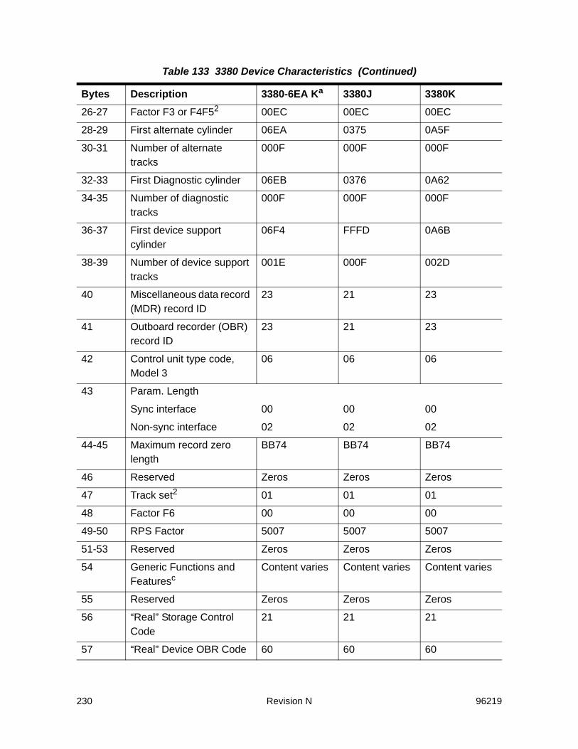
230 Revision N 96219
26-27 Factor F3 or F4F52 00EC 00EC 00EC
28-29 First alternate cylinder 06EA 0375 0A5F
30-31 Number of alternate tracks
000F 000F 000F
32-33 First Diagnostic cylinder 06EB 0376 0A62
34-35 Number of diagnostic tracks
000F 000F 000F
36-37 First device support cylinder
06F4 FFFD 0A6B
38-39 Number of device support tracks
001E 000F 002D
40 Miscellaneous data record (MDR) record ID
23 21 23
41 Outboard recorder (OBR) record ID
23 21 23
42 Control unit type code, Model 3
06 06 06
43 Param. Length
Sync interface 00 00 00
Non-sync interface 02 02 02
44-45 Maximum record zero length
BB74 BB74 BB74
46 Reserved Zeros Zeros Zeros
47 Track set2 01 01 01
48 Factor F6 00 00 00
49-50 RPS Factor 5007 5007 5007
51-53 Reserved Zeros Zeros Zeros
54 Generic Functions and Featuresc
Content varies Content varies Content varies
55 Reserved Zeros Zeros Zeros
56 “Real” Storage Control Code
21 21 21
57 “Real” Device OBR Code 60 60 60
Table 133 3380 Device Characteristics (Continued)
Bytes Description 3380-6EA Ka 3380J 3380K
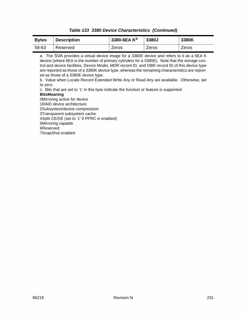
96219 Revision N 231
58-63 Reserved Zeros Zeros Zeros
a. The SVA provides a virtual device image for a 3380E device and refers to it as a 6EA K device (where 6EA is the number of primary cylinders for a 3380E). Note that the storage con-trol and device facilities, Device Model, MDR record ID, and OBR record ID of this device type are reported as those of a 3380K device type, whereas the remaining characteristics are report-ed as those of a 3380E device type.b. Value when Locate Record Extended Write Any or Read Any are available. Otherwise, set to zero.c. Bits that are set to ‘1’ in this byte indicate the function or feature is supported: BitsMeaning 0Mirroring active for device 1RAID device architecture 2Subsystem/device compression 3Transparent subsystem cache 4Split CE/DE (set to ‘1’ if PPRC is enabled) 5Mirroring capable 6Reserved 7SnapShot enabled
Table 133 3380 Device Characteristics (Continued)
Bytes Description 3380-6EA Ka 3380J 3380K

232 Revision N 96219
96219 Revision N 233
DRead Subsystem Data (RSSD) Differences
Differences Between IBM RSSD and the SVA RSSDThe SVA’s fully buffered architecture requires different caching algorithms than those used by the 3990-3. Consequently, some of the cache hits, pre-stages and destages that occur in an SVA subsystem cannot be represented in the IBM-compatible statistical counters. In addition, the SVA does not treat some exception conditions in the Read Subsystem Data (RSSD) counters in the same way as the 3990-3.The following paragraphs describe the major differences between 3990 RSSD and the SVA RSSD when using a program designed to collect and report 3990 subsystem data. The RSSD columns of the counter update tables describe when counters are updated. These RSSD columns are found in Table 134 on page 237 through Table 152 on page 265.
Hits and MissesIn the SVA, all hits and misses are counted as they occur, as long as they are within the constraints for counting hits and misses as described in the RSSD column of the counter update tables. (Refer to pages 237 to 265.) This rule includes Format Write operations for which the SVA may perform stages in some instances in which the 3990 does not. The SVA never stages the following writes, instead they are always counted as hits.• Predictable write operations• Write Count, Key, and Data Next Track commands with a standard
Record Zero. The 3990 counts neither hits nor misses, only writes. • Locate Record or Locate Record Extended commands with a Write
Track operation and a standard Record Zero • Locate Record or Locate Record Extended commands with a
Format Write operation that has Index or Home Address orientation.

234 Revision N 96219
Pre-stagingAll Read Track, Read Multiple Count, Key, and Data, or Read or Update Write operations with a Locate Record count large enough to span multiple tracks may cause within-chain pre-staging in the SVA. Note that the SVA never pre-stages on Format Write operations. The SVA counts sequential pre-stages only (both within-chain and end-of-chain). This count is found in Bytes 60-63. The 3990 does not perform within-chain pre-staging. The net result of counting the SVA-unique pre-stages is that, all else being equal, the SVA reports a higher pre-stage count than does the 3990.
Search counts incremented at Locate RecordThe SVA, unlike the 3990, initiates a search at the time a Locate Record or Locate Record Extended command is processed (unless Index orientation is specified), and increments the search counts if the first command in the domain of the Locate Record operation fails. If the result of the search is a hit (including those operations enumerated in the preceeding, which are always hits), the search hit counts are incremented. If it is a miss, the stage counts are incremented. If the Locate Record command is followed by a successful write operation, the write counts are incremented, rather than the search counts.
DestagesAll else being equal, the SVA reports a higher destage count than the 3990, since the history of destaged tracks is not easily known: tracks that were never counted as staged can be included in the destaged count.
NVS constraintThe SVA always reports zeros in this counter because all writes must go through cache. The 3990 can have positive values in this count.
Force Bypass CacheThe SVA never forces bypass cache mode, and never updates the RSSD counters as if it had. The 3990 forces bypass cache mode for certain commands (e.g., a Read IPL, Space Count, or Recalibrate command), and certain Define Extent options (e.g., when the file mask specifies “permit all writes”).
Non-primary cylindersAccesses to non-primary cylinders are always counted as hits by the SVA, as long as the rules for the type of access and current caching

96219 Revision N 235
status (as described in the table for the counter) allow recording of hits. The 3990 always goes to DASD to access non-primary cylinders.
C0H0The SVA does not treat accesses to C0H0 differently from accesses to other tracks. The 3990 always goes to DASD to access C0H0.
Major Differences between the SVA RSSD and ECAMThe preceding paragraphs described the major differences between 3990 RSSD and the SVA RSSD when using a program designed to collect and report 3990 subsystem data. However, there are programs, such as SVAA Subsystem Reporting, specifically designed to collect and report data for an SVA subsystem. These programs receive their data through the SVA’s Extended Control and Monitoring (ECAM) interface. In some cases, the data provided by programs using the ECAM interface is different from the SVA RSSD data. The following paragraphs describe the major differences between the SVA RSSD and the data provided through the ECAM interface. The ECAM columns of the counter update tables on pages 237 to 265 describe when counters are updated.
Write hits and missesAll write hits and misses are counted in ECAM as they occur, not just those with CFW or DFW on; and irrespective of device or functional control unit (FCU) caching status.
Cache Fast WriteThe SVA treats all writes, including those with cache fast write in the define extent CCW, as DASD fast writes. The four CFW counters (reads, read hits, writes, write hits) are always set to zero in ECAM, and operations specifying CFW are counted as if CFW was not specified.
Write OperationsIn ECAM, all writes are counted as DFW writes. Therefore, the normal writes counter is always identical to the DFW normal writes counter, and the sequential writes counter is always identical to the DFW sequential writes counter.
Bypass cache and ICL operationsSince bypass cache and inhibit cache loading operations use sequential caching algorithms in the SVA, they are counted as

236 Revision N 96219
sequential operations. Therefore, ECAM always reports zero in the bypass and ICL counters.
Effect of cache statusDepending on the cache status, the SVA RSSD and ECAM may increment counters differently.• If cache is deactivated for the FCU, all counters reported by the
RSSD command are zeros. However, the ECAM counters continue to be incremented, and are reported as actuals.
• If cache is deactivated for the device, ECAM reports the actual counts regardless of the device caching status; however, the following counts are not incremented in RSSD if caching is deactivated for the device:- Read normal hits (8-11) - DFW normal hits (16-19) - Read sequential hits (24-27)- DFW sequential hits (32-35) - Search/read CFW reqs (36-39) - Search/read CFW hits (40-43) - Write CFW reqs (44-47) - Write CFW hits (48-51) - Sequential stages (60-63)- Stages (64-67) - destages (68-71) - DFW normal writes (76-79) - DFW sequential writes (80-83)
• If DFW is deactivated for the device or NVS is deactivated for the FCU (DFW disabled), device DFW status and FCU NVS status have no effect on caching algorithms for the SVA or for ECAM. However, in the 3990, DFW writes are counted as non-DFW writes when DFW is disabled. The following counts are not incremented in RSSD if DFW is disabled:- DFW normal hits (16-19) - DFW sequential hits (32-35) - DFW normal writes (76-79) - DFW sequential writes (80-83)
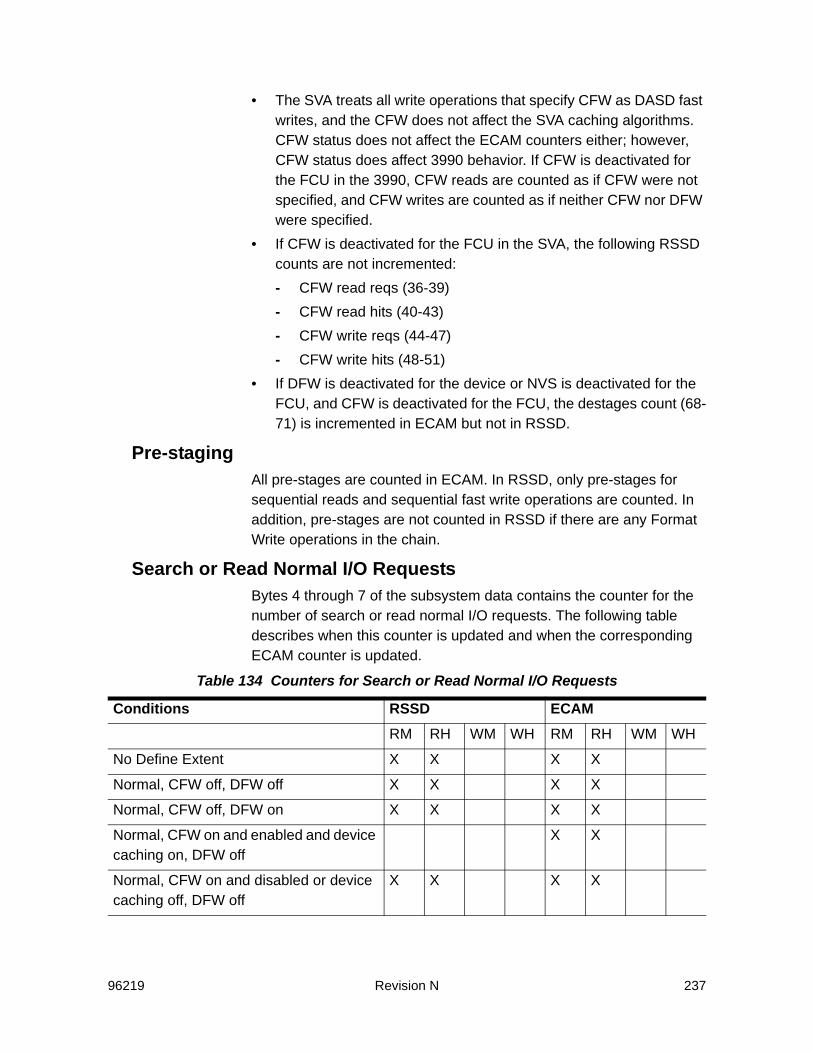
96219 Revision N 237
• The SVA treats all write operations that specify CFW as DASD fast writes, and the CFW does not affect the SVA caching algorithms. CFW status does not affect the ECAM counters either; however, CFW status does affect 3990 behavior. If CFW is deactivated for the FCU in the 3990, CFW reads are counted as if CFW were not specified, and CFW writes are counted as if neither CFW nor DFW were specified.
• If CFW is deactivated for the FCU in the SVA, the following RSSD counts are not incremented:- CFW read reqs (36-39) - CFW read hits (40-43) - CFW write reqs (44-47) - CFW write hits (48-51)
• If DFW is deactivated for the device or NVS is deactivated for the FCU, and CFW is deactivated for the FCU, the destages count (68-71) is incremented in ECAM but not in RSSD.
Pre-stagingAll pre-stages are counted in ECAM. In RSSD, only pre-stages for sequential reads and sequential fast write operations are counted. In addition, pre-stages are not counted in RSSD if there are any Format Write operations in the chain.
Search or Read Normal I/O RequestsBytes 4 through 7 of the subsystem data contains the counter for the number of search or read normal I/O requests. The following table describes when this counter is updated and when the corresponding ECAM counter is updated.
Table 134 Counters for Search or Read Normal I/O Requests
Conditions RSSD ECAMRM RH WM WH RM RH WM WH
No Define Extent X X X X
Normal, CFW off, DFW off X X X X
Normal, CFW off, DFW on X X X X
Normal, CFW on and enabled and device caching on, DFW off
X X
Normal, CFW on and disabled or device caching off, DFW off
X X X X

238 Revision N 96219
Normal, CFW on and enabled and device caching on, DFW on
X X
Normal, CFW on and disabled or device caching off, DFW on
X X X X
ICL, CFW off, DFW off, device caching on
X
ICL, CFW off, DFW off, device caching off
ICL, CFW off, DFW on, device caching on
X
ICL, CFW off, DFW on, device caching off
ICL, CFW on and enabled and device caching off, DFW off
ICL, CFW on and disabled or device caching on, DFW off
X
ICL, CFW on and enabled or device caching off, DFW on
ICL, CFW on and disabled and device caching on, DFW on
X
3990 and the SVA RSSD:Increment: 1. On all normal reads with CFW off.2. On normal reads with CFW on but disabled for the FCU, or with device caching disabled. 3. If device caching is active, on ICL read hits with CFW off, and on ICL read hits with CFW on but disabled for
FCU.ECAM: Increment on all normal reads including CFW normal reads. Do not increment on ICL read hits. (ICL is counted as sequential.)
Abbreviations:RSSD = Read Subsystem DataECAM = Extended Control and MonitoringRM = read missRH = read hitWM = write miss
WH = write hitCFW = cache fast writeDFW = DASD fast writeICL = inhibit cache loadingFCU = Functional Control Unit
Table 134 Counters for Search or Read Normal I/O Requests (Continued)
Conditions RSSD ECAM

96219 Revision N 239
Search or Read Normal I/O Request HitsBytes 8 through 11 of the subsystem data contains the counter for the number of search or read normal I/O request hits. The following table describes when this counter is updated and when the corresponding ECAM counter is updated.
Table 135 Counters for Search or Read Normal I/O Request Hits
Conditions RSSD ECAMRM RH WM WH RM RH WM WH
No Define Extent X X
Normal, CFW off, DFW off X X
Normal, CFW off, DFW on X X
Normal, CFW on and enabled, DFW off X
Normal, CFW on and disabled, DFW off X X
Normal, CFW on and enabled, DFW on X
Normal, CFW on and disabled, DFW on X X
ICL, CFW off, DFW off X
ICL, CFW off, DFW on X
ICL, CFW on and enabled, DFW off
ICL, CFW on and disabled, DFW off X
ICL, CFW on and enabled, DFW on
ICL, CFW on and disabled, DFW on X
SVA RSSD:Increment:1. On normal reads with CFW off or with CFW on but disabled for the FCU. 2. On ICL read hits with CFW off or with CFW on but disabled for the FCU.ECAM: Increment on all normal reads including CFW normal reads. Do not increment on ICL read hits. (ICL is counted as sequential.)
Abbreviations:RSSD = Read Subsystem DataECAM = Extended Control and MonitoringRM = read missRH = read hitWM = write miss
WH = write hitCFW = cache fast writeDFW = DASD fast writeICL = inhibit cache loadingFCU = Functional Control Unit

240 Revision N 96219
Write Normal I/O RequestsBytes 12 through 15 of the subsystem data contains the counter for the number of write normal I/O requests. The following table describes when this counter is updated and when the corresponding ECAM counter is updated.
Table 136 Counters for Write Normal I/O Requests
Conditions RSSD ECAMRM RH WM WH RM RH WM WH
No Define Extent X X X X
Normal, CFW off, DFW off X X X X
Normal, CFW off, DFW on X X X X
Normal, CFW on and enabled and device caching on, DFW off
X X
Normal, CFW on and disabled or device caching off, DFW off
X X X X
Normal, CFW on and enabled or device caching on, DFW on
X X
Normal, CFW on and disabled or device caching off, DFW on
X X X X
ICL, CFW off, DFW on and enabled and NVS enabled and device caching on
X
ICL, CFW off, DFW on and disabled or NVS disabled or device caching off
SVA RSSD:Increment:1. On normal writes with CFW off. 2. On normal writes with CFW on but disabled for the FCU, or with device caching disabled.3. If device caching is active, on ICL write hits with CFW off and DFW on and enabled for the device
and NVS is enabled for the FCU. ECAM: Increment on all normal write hits. (The SVA treats all writes, including CFW writes, as DFW writes). This counter always equals the DFW normal writes. Do not increment on ICL write hits. (ICL is counted as sequential.)

96219 Revision N 241
Abbreviations:RSSD = Read Subsystem DataECAM = Extended Control and MonitoringRM = read missRH = read hitWM = write miss
WH = write hitCFW = cache fast writeDFW = DASD fast writeICL = inhibit cache loadingFCU = Functional Control Unit
Table 136 Counters for Write Normal I/O Requests
Conditions RSSD ECAM

242 Revision N 96219
DASD Fast Write I/O Request HitsBytes 16 through 19 of the subsystem data contains the counter for the number of DASD fast write I/O request hits. The following table describes when this counter is updated and when the corresponding ECAM counter is updated.
Table 137 Counters for DASD Fast Write I/O Request Hits
Conditions RSSD ECAMRM RH WM WH RM RH WM WH
No Define Extent, DFW enabled and NVS enabled
X X
No Define Extent, DFW disabled and NVS disabled
X
Normal, CFW off, DFW off X
Normal, CFW off, DFW on and enabled and NVS enabled
X X
Normal, CFW off, DFW on and disabled or NVS disabled
X
Normal, CFW on, DFW off X
Normal, CFW on, DFW on X
ICL, CFW off, DFW on and enabled and NVS enabled
X
ICL, CFW off, DFW on and disabled or NVS disabled
SVA RSSD:Caching and DFW must be enabled for the device and NVS enabled for the FCU for this counter to increment. Increment on normal or ICL DFW write hits with CFW off.ECAM: Increment on all normal write hits. (The SVA treats all writes, including CFW writes, as DFW writes). Do not increment on ICL write hits. (ICL is counted as sequential.)
Abbreviations:RSSD = Read Subsystem DataECAM = Extended Control and MonitoringRM = read missRH = read hitWM = write miss
WH = write hitCFW = cache fast writeDFW = DASD fast writeICL = inhibit cache loadingFCU = Functional Control Unit
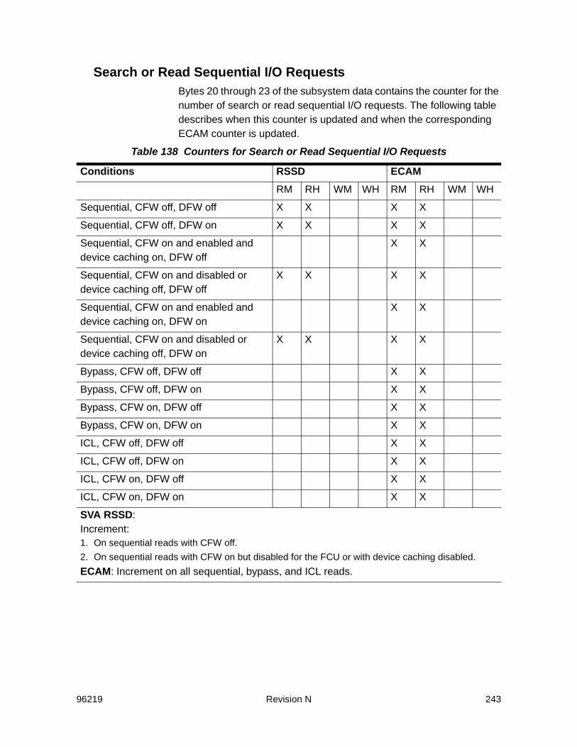
96219 Revision N 243
Search or Read Sequential I/O RequestsBytes 20 through 23 of the subsystem data contains the counter for the number of search or read sequential I/O requests. The following table describes when this counter is updated and when the corresponding ECAM counter is updated.
Table 138 Counters for Search or Read Sequential I/O Requests
Conditions RSSD ECAMRM RH WM WH RM RH WM WH
Sequential, CFW off, DFW off X X X X
Sequential, CFW off, DFW on X X X X
Sequential, CFW on and enabled and device caching on, DFW off
X X
Sequential, CFW on and disabled or device caching off, DFW off
X X X X
Sequential, CFW on and enabled and device caching on, DFW on
X X
Sequential, CFW on and disabled or device caching off, DFW on
X X X X
Bypass, CFW off, DFW off X X
Bypass, CFW off, DFW on X X
Bypass, CFW on, DFW off X X
Bypass, CFW on, DFW on X X
ICL, CFW off, DFW off X X
ICL, CFW off, DFW on X X
ICL, CFW on, DFW off X X
ICL, CFW on, DFW on X X
SVA RSSD: Increment:1. On sequential reads with CFW off.2. On sequential reads with CFW on but disabled for the FCU or with device caching disabled.ECAM: Increment on all sequential, bypass, and ICL reads.
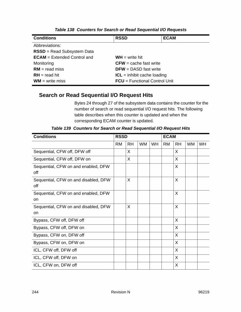
244 Revision N 96219
Search or Read Sequential I/O Request HitsBytes 24 through 27 of the subsystem data contains the counter for the number of search or read sequential I/O request hits. The following table describes when this counter is updated and when the corresponding ECAM counter is updated.
Abbreviations:RSSD = Read Subsystem DataECAM = Extended Control and MonitoringRM = read missRH = read hitWM = write miss
WH = write hitCFW = cache fast writeDFW = DASD fast writeICL = inhibit cache loadingFCU = Functional Control Unit
Table 139 Counters for Search or Read Sequential I/O Request Hits
Conditions RSSD ECAMRM RH WM WH RM RH WM WH
Sequential, CFW off, DFW off X X
Sequential, CFW off, DFW on X X
Sequential, CFW on and enabled, DFW off
X
Sequential, CFW on and disabled, DFW off
X X
Sequential, CFW on and enabled, DFW on
X
Sequential, CFW on and disabled, DFW on
X X
Bypass, CFW off, DFW off X
Bypass, CFW off, DFW on X
Bypass, CFW on, DFW off X
Bypass, CFW on, DFW on X
ICL, CFW off, DFW off X
ICL, CFW off, DFW on X
ICL, CFW on, DFW off X
Table 138 Counters for Search or Read Sequential I/O Requests
Conditions RSSD ECAM
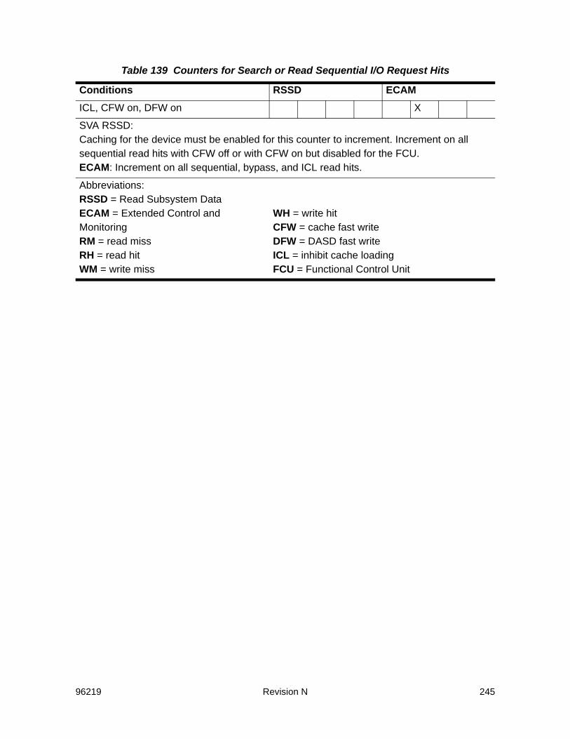
96219 Revision N 245
ICL, CFW on, DFW on X
SVA RSSD:Caching for the device must be enabled for this counter to increment. Increment on all sequential read hits with CFW off or with CFW on but disabled for the FCU.ECAM: Increment on all sequential, bypass, and ICL read hits.
Abbreviations:RSSD = Read Subsystem DataECAM = Extended Control and MonitoringRM = read missRH = read hitWM = write miss
WH = write hitCFW = cache fast writeDFW = DASD fast writeICL = inhibit cache loadingFCU = Functional Control Unit
Table 139 Counters for Search or Read Sequential I/O Request Hits
Conditions RSSD ECAM

246 Revision N 96219
Write Sequential I/O RequestsBytes 28 through 31 of the subsystem data contains the counter for the number of write sequential I/O requests. The following table describes when this counter is updated and when the corresponding ECAM counter is updated.
Table 140 Counters for Write Sequential I/O Requests
Conditions RSSD ECAMRM RH WM WH RM RH WM WH
Sequential, CFW off, DFW off X X X X
Sequential, CFW off, DFW on X X X X
Sequential, CFW on and enabled and device caching on, DFW off
X X
Sequential, CFW on and disabled and device caching off, DFW off
X X
Sequential, CFW on and disabled and device caching on, DFW on
X X
Sequential, CFW on and disabled and device caching off, DFW on
X X
Bypass, CFW off, DFW off X X
Bypass, CFW off, DFW on X X
Bypass, CFW on, DFW off X X
Bypass, CFW on, DFW on X X
ICL, CFW off, DFW off X X
ICL, CFW off, DFW on X X
ICL, CFW on, DFW off X X
ICL, CFW on, DFW on X X
SVA RSSD: Increment:1. On sequential writes with CFW off.2. On sequential writes with CFW on but disabled for FCU or with device caching disabled.ECAM: Increment on all sequential, bypass, and ICL writes.

96219 Revision N 247
DASD Fast Write Sequential I/O Request HitsBytes 32 through 35 of the subsystem data contains the counter for the number of DASD fast write sequential I/O request hits. The following table describes when this counter is updated and when the corresponding ECAM counter is updated.
Abbreviations:RSSD = Read Subsystem DataECAM = Extended Control and MonitoringRM = read missRH = read hitWM = write miss
WH = write hitCFW = cache fast writeDFW = DASD fast writeICL = inhibit cache loadingFCU = Functional Control Unit
Table 141 Counters for DASD Fast Write Sequential I/O Request Hits
Conditions RSSD ECAMRM RH WM WH RM RH WM WH
Sequential, CFW off, DFW off X
Sequential, CFW off, DFW on and enabled and NVS enabled
X X
Sequential, CFW off, DFW on and disabled or NVS disabled
X
Sequential, CFW on, DFW off X
Sequential, CFW on, DFW on X
Bypass, CFW off, DFW off X
Bypass, CFW off, DFW on X
Bypass, CFW on, DFW off X
Bypass, CFW on, DFW on X
ICL, CFW off, DFW off X
ICL, CFW off, DFW on X
ICL, CFW on, DFW off X
ICL, CFW on, DFW on X
Table 140 Counters for Write Sequential I/O Requests
Conditions RSSD ECAM
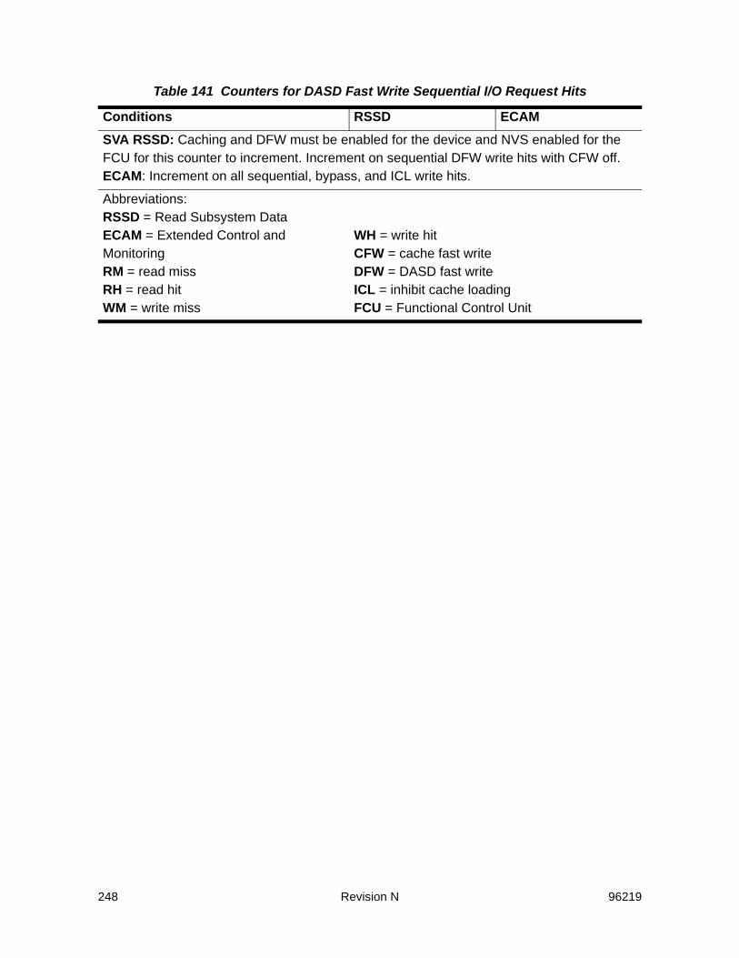
248 Revision N 96219
SVA RSSD: Caching and DFW must be enabled for the device and NVS enabled for the FCU for this counter to increment. Increment on sequential DFW write hits with CFW off.ECAM: Increment on all sequential, bypass, and ICL write hits.
Abbreviations:RSSD = Read Subsystem DataECAM = Extended Control and MonitoringRM = read missRH = read hitWM = write miss
WH = write hitCFW = cache fast writeDFW = DASD fast writeICL = inhibit cache loadingFCU = Functional Control Unit
Table 141 Counters for DASD Fast Write Sequential I/O Request Hits
Conditions RSSD ECAM

96219 Revision N 249
Search or Read Cache Fast Write I/O RequestsBytes 36 through 39 of the subsystem data contains the counter for the number of search or read cache fast write I/O requests. The following table describes when this counter is updated and when the corresponding ECAM counter is updated.
Table 142 Counters for Search or Read Cache Fast Write I/O Requests
Conditions RSSD ECAMRM RH WM WH RM RH WM WH
Normal, CFW on and enabled, DFW off X X
Normal, CFW on and disabled, DFW off
Normal, CFW on and enabled, DFW on X X
Normal, CFW on and disabled, DFW on
Sequential, CFW on and enabled, DFW off
X X
Sequential, CFW on and disabled, DFW off
Sequential, CFW on and enabled, DFW on
X X
Sequential, CFW on and disabled, DFW on
ICL, CFW on and enabled, DFW off X
ICL, CFW on and disabled, DFW off
ICL, CFW on and enabled, DFW on X
ICL, CFW on and disabled, DFW on
SVA RSSD: Caching must be enabled for the device and CFW enabled for the FCU for this counter to increment. Increment:1. On normal reads with CFW on. 2. On sequential reads with CFW on. 3. On ICL read hits with CFW on.ECAM: Always set to zero.

250 Revision N 96219
Search or Read Cache Fast Write I/O Request HitsBytes 40 through 43 of the subsystem data contains the counter for the number of search or read cache fast write I/O request hits. The following table describes when this counter is updated.
Abbreviations:RSSD = Read Subsystem DataECAM = Extended Control and MonitoringRM = read missRH = read hitWM = write miss
WH = write hitCFW = cache fast writeDFW = DASD fast writeICL = inhibit cache loadingFCU = Functional Control Unit
Table 143 Counters for Search or Read Cache Fast Write I/O Request Hits
Conditions RSSD ECAMRM RH WM WH RM RH WM WH
Normal, CFW on and enabled, DFW off X
Normal, CFW on and disabled, DFW off
Normal, CFW on and enabled, DFW on X
Normal, CFW on and disabled, DFW on
Sequential, CFW on and enabled, DFW off
X
Sequential, CFW on and disabled, DFW off
Sequential, CFW on and enabled, DFW on
X
Sequential, CFW on and disabled, DFW on
ICL, CFW on and enabled, DFW off X
ICL, CFW on and disabled, DFW off
ICL, CFW on and enabled, DFW on X
ICL, CFW on and disabled, DFW on
Table 142 Counters for Search or Read Cache Fast Write I/O Requests
Conditions RSSD ECAM
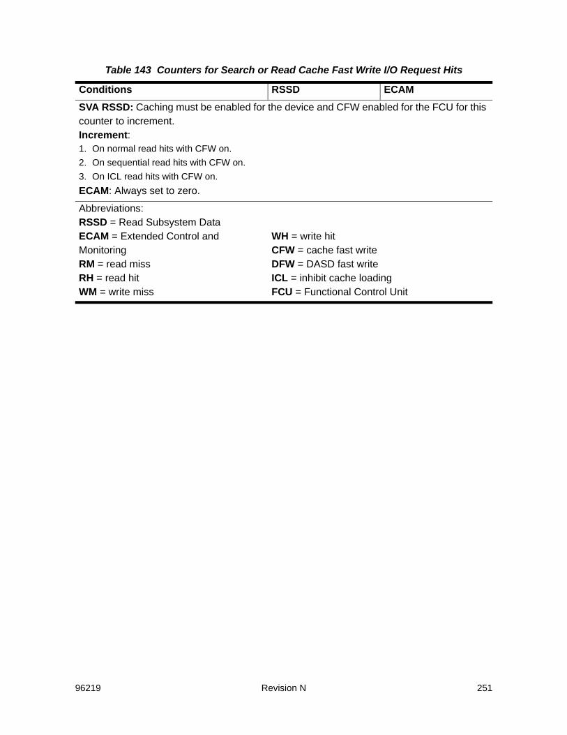
96219 Revision N 251
SVA RSSD: Caching must be enabled for the device and CFW enabled for the FCU for this counter to increment. Increment:1. On normal read hits with CFW on. 2. On sequential read hits with CFW on. 3. On ICL read hits with CFW on.ECAM: Always set to zero.
Abbreviations:RSSD = Read Subsystem DataECAM = Extended Control and MonitoringRM = read missRH = read hitWM = write miss
WH = write hitCFW = cache fast writeDFW = DASD fast writeICL = inhibit cache loadingFCU = Functional Control Unit
Table 143 Counters for Search or Read Cache Fast Write I/O Request Hits
Conditions RSSD ECAM

252 Revision N 96219
Cache Fast Write I/O RequestsBytes 44 through 47 of the subsystem data contains the counter for the number of cache fast write I/O requests. The following table describes when this counter is updated and when the corresponding ECAM counter is updated.
Table 144 Counters for Cache Fast Write I/O Requests
Conditions RSSD ECAMRM RH WM WH RM RH WM WH
Normal, CFW on and enabled, DFW off X X
Normal, CFW on and disabled, DFW off
Normal, CFW on and enabled, DFW on X X
Normal, CFW on and disabled, DFW on
Sequential, CFW on and enabled, DFW off
X X
Sequential, CFW on and disabled, DFW off
Sequential, CFW on and enabled, DFW on
X X
Sequential, CFW on and disabled, DFW on
ICL, CFW on and enabled, DFW off X
ICL, CFW on and disabled, DFW off
ICL, CFW on and enabled, DFW on X
ICL, CFW on and disabled, DFW on
SVA RSSD: Caching must be enabled for the device and CFW enabled for the FCU for this counter to increment. Increment:1. On normal writes with CFW on. 2. On sequential writes with CFW on. 3. On ICL write hits with CFW on.ECAM: Always set to zero. (The SVA treats all writes, including CFW writes, as DFW writes).

96219 Revision N 253
Abbreviations:RSSD = Read Subsystem DataECAM = Extended Control and MonitoringRM = read missRH = read hitWM = write miss
WH = write hitCFW = cache fast writeDFW = DASD fast writeICL = inhibit cache loadingFCU = Functional Control Unit
Table 144 Counters for Cache Fast Write I/O Requests
Conditions RSSD ECAM

254 Revision N 96219
Cache Fast Write I/O Request HitsBytes 48 through 51 of the subsystem data contains the counter for the number of cache fast write I/O request hits. The following table describes when this counter is updated and when the corresponding ECAM counter is updated.
Table 145 Counters for Cache Fast Write I/O Request Hits
Conditions RSSD ECAMRM RH WM WH RM RH WM WH
Normal, CFW on and enabled, DFW off X
Normal, CFW on and disabled, DFW off
Normal, CFW on and enabled, DFW on X
Normal, CFW on and disabled, DFW on
Sequential, CFW on and enabled, DFW off
X
Sequential, CFW on and disabled, DFW off
Sequential, CFW on and enabled, DFW on
X
Sequential, CFW on and disabled, DFW on
ICL, CFW on and enabled, DFW off X
ICL, CFW on and disabled, DFW off
ICL, CFW on and enabled, DFW on X
ICL, CFW on and disabled, DFW on
SVA RSSD: Caching must be enabled for the device and CFW enabled for the FCU for this counter to increment. Increment:1. On normal write hits with CFW on. 2. On sequential write hits with CFW on. 3. On ICL write hits with CFW on.ECAM: Always set to zero. (The SVA treats all writes, including CFW writes, as DFW writes).
96219 Revision N 255
Abbreviations:RSSD = Read Subsystem DataECAM = Extended Control and MonitoringRM = read missRH = read hitWM = write miss
WH = write hitCFW = cache fast writeDFW = DASD fast writeICL = inhibit cache loadingFCU = Functional Control Unit
Table 145 Counters for Cache Fast Write I/O Request Hits
Conditions RSSD ECAM

256 Revision N 96219
Inhibit Cache Loading I/O RequestsBytes 52 through 55 of the subsystem data contains the counter for the number of inhibit cache loading requests. The following table describes when this counter is updated and when the corresponding ECAM counter is updated.
Table 146 Counters for Inhibit Cache Loading I/O Requests
Conditions RSSD ECAMRM RH WM WH RM RH WM WH
ICL, CFW off, DFW off, device caching on
X X X
ICL, CFW off, DFW off, device caching off
X X X X
ICL, CFW off, DFW on and enabled and NVS enabled, device caching on
X X
ICL, CFW off, DFW on and disabled or NVS disabled, device caching on
X X X
ICL, CFW off, DFW on, device caching off
X X X X
ICL, CFW on and enabled and device caching on, DFW off
X X
ICL, CFW on and disabled and device caching on, DFW off
X X X
ICL, CFW on and device caching off, DFW off
X X X X
ICL, CFW on and enabled and device caching on, DFW on
X X
ICL, CFW on and disabled and device caching on, DFW on
X X X
ICL, CFW on and device caching off, DFW on
X X X X

96219 Revision N 257
Bypass Cache I/O RequestsBytes 56 through 59 of the subsystem data contains the counter for the number of bypass cache I/O requests. The following table describes when this counter is updated and when the corresponding ECAM counter is updated.
SVA RSSD: Increment:1. On all ICL misses2. On all ICL reads or writes with device caching off.3. On ICL write hits with DFW off and CFW off.4. On ICL write hits with DFW on and CFW off and either DFW disabled for the device or NVS disabled for the
FCU.5. On ICL write hits with CFW on but disabled for the FCU.ECAM: Always set to zero (counted with sequential).
Abbreviations:RSSD = Read Subsystem DataECAM = Extended Control and MonitoringRM = read missRH = read hitWM = write miss
WH = write hitCFW = cache fast writeDFW = DASD fast writeICL = inhibit cache loadingFCU = Functional Control Unit
Table 147 Counters for Bypass Cache I/O Requests
Conditions RSSD ECAMRM RH WM WH RM RH WM WH
Bypass cache, CFW off, DFW off X X X X
Bypass cache, CFW off, DFW on X X X X
Bypass cache, CFW on, DFW off X X X X
Bypass cache, CFW on, DFW on X X X X
SVA RSSD: Increment on all bypass cache requests.ECAM: Always set to zero (counted with sequential).
Table 146 Counters for Inhibit Cache Loading I/O Requests
Conditions RSSD ECAM

258 Revision N 96219
Sequential DASD-to-Cache Transfer OperationsBytes 60 through 63 of the subsystem data contains the counter for the number of sequential DASD-to-cache transfer operations. The following table describes when this counter is updated and when the corresponding ECAM counter is updated.
Abbreviations:RSSD = Read Subsystem DataECAM = Extended Control and MonitoringRM = read missRH = read hitWM = write miss
WH = write hitCFW = cache fast writeDFW = DASD fast writeICL = inhibit cache loadingFCU = Functional Control Unit
Table 148 Counters for Sequential DASD-to-Cache Transfer Operations
Conditions RSSD ECAMRM RH WM WH RM RH WM WH
Normal, CFW off, DFW off X X X X
Normal, CFW off, DFW on X X X X
Normal, CFW on, DFW off X X X X
Normal, CFW on, DFW on X X X X
Sequential, CFW off, DFW off X X
Sequential, CFW off, DFW on and enabled and NVS enabled
X X X X X X X X
Sequential, CFW off, DFW on and disabled or NVS disabled
X X X X X X
Sequential, CFW on and enabled, DFW off
X X X X X X X X
Sequential, CFW on and disabled, DFW off
X X X X X X
Sequential, CFW on and enabled, DFW on
X X X X X X X X
Sequential, CFW on and disabled, DFW on
X X X X X X
Bypass, CFW off, DFW off X X X X
Table 147 Counters for Bypass Cache I/O Requests
Conditions RSSD ECAM
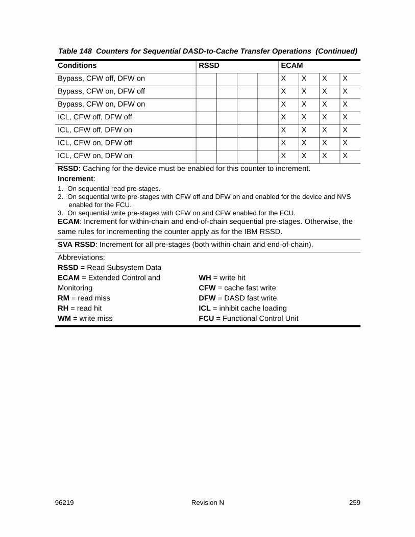
96219 Revision N 259
Bypass, CFW off, DFW on X X X X
Bypass, CFW on, DFW off X X X X
Bypass, CFW on, DFW on X X X X
ICL, CFW off, DFW off X X X X
ICL, CFW off, DFW on X X X X
ICL, CFW on, DFW off X X X X
ICL, CFW on, DFW on X X X X
RSSD: Caching for the device must be enabled for this counter to increment.Increment: 1. On sequential read pre-stages. 2. On sequential write pre-stages with CFW off and DFW on and enabled for the device and NVS
enabled for the FCU. 3. On sequential write pre-stages with CFW on and CFW enabled for the FCU.ECAM: Increment for within-chain and end-of-chain sequential pre-stages. Otherwise, the same rules for incrementing the counter apply as for the IBM RSSD.
SVA RSSD: Increment for all pre-stages (both within-chain and end-of-chain).
Abbreviations:RSSD = Read Subsystem DataECAM = Extended Control and MonitoringRM = read missRH = read hitWM = write miss
WH = write hitCFW = cache fast writeDFW = DASD fast writeICL = inhibit cache loadingFCU = Functional Control Unit
Table 148 Counters for Sequential DASD-to-Cache Transfer Operations (Continued)
Conditions RSSD ECAM

260 Revision N 96219
DASD-to-Cache Transfer OperationsBytes 64 through 67 of the subsystem data contains the counter for the number of DASD-to-cache transfer operations. The following table describes when this counter is updated.
Table 149 Counters for DASD-to-Cache Transfer Operations (Sheet 1 of 3)
Conditions RSSD ECAMRM RH WM WH RM RH WM WH
No Define Extend, DFW enabled and NVS enabled
X X X X
No Define Extent, DFW disabled or NVS disabled
X X X
Normal, CFW off, DFW off X X X
Normal, CFW off, DFW on and enabled and NVS enabled
X X X X
Normal, CFW off, DFW on and disabled or NVS disabled
X X X
Normal, CFW on and enabled, DFW off X X X X
Normal, CFW on and disabled, DFW off X X X
Normal, CFW on and enabled, DFW on X X X X
Normal, CFW on and disabled, DFW on X X X
Sequential, CFW off, DFW off X X X
Sequential, CFW off, DFW on and enabled and NVS enabled
X X X X
Sequential, CFW off, DFW on and disabled or NVS disabled
X X X
Sequential, CFW on and enabled, DFW off
X X X X
Sequential, CFW on and disabled, DFW off
X X X
Sequential, CFW on and enabled, DFW on
X X X X
Sequential, CFW on and disabled, DFW on
X X X
96219 Revision N 261
Abbreviations:RSSD = Read Subsystem DataECAM = Extended Control and MonitoringRM = read missRH = read hitWM = write miss
WH = write hitCFW = cache fast writeDFW = DASD fast writeICL = inhibit cache loadingFCU = Functional Control Unit
Table 149 Counters for DASD-to-Cache Transfer Operations (Sheet 2 of 3)
Conditions RSSD ECAM

262 Revision N 96219
Cache-to-DASD Transfer OperationsBytes 68 through 71 of the subsystem data contains the counter for the number of cache-to-DASD transfer operations.
Bypass, CFW off, DFW off X X
Bypass, CFW off, DFW on X X
Bypass, CFW on, DFW off X X
Bypass, CFW on, DFW on X X
ICL, CFW off, DFW off X X
ICL, CFW off, DFW on X X
ICL, CFW on, DFW off X X
ICL, CFW on, DFW on X X
SVA RSSD: Caching for the device must be enabled for this counter to increment. Increment: 1. On normal and sequential read misses.2. On normal and sequential write misses with CFW off and DFW on and enabled for the device and NVS enabled for the
FCU.3. On normal and sequential write misses with CFW on and CFW enabled for the FCU. ECAM: Increment for all read and write misses.
SVA RSSD: Increment for all pre-stages (both within-chain and end-of-chain).
Abbreviations:RSSD = Read Subsystem DataECAM = Extended Control and MonitoringRM = read missRH = read hitWM = write miss
WH = write hitCFW = cache fast writeDFW = DASD fast writeICL = inhibit cache loadingFCU = Functional Control Unit
Table 150 Counters for Cache-to-DASD Transfer Operations
Conditions RSSD ECAMRM RH WM WH RM RH WM WH
(See the following notes.)
Table 149 Counters for DASD-to-Cache Transfer Operations (Sheet 3 of 3)
Conditions RSSD ECAM
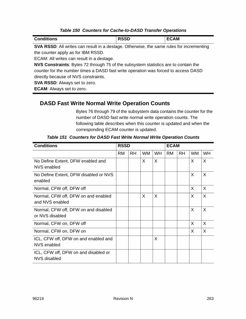
96219 Revision N 263
DASD Fast Write Normal Write Operation CountsBytes 76 through 79 of the subsystem data contains the counter for the number of DASD fast write normal write operation counts. The following table describes when this counter is updated and when the corresponding ECAM counter is updated.
SVA RSSD: All writes can result in a destage. Otherwise, the same rules for incrementing the counter apply as for IBM RSSD.ECAM: All writes can result in a destage.NVS Constraints: Bytes 72 through 75 of the subsystem statistics are to contain the counter for the number times a DASD fast write operation was forced to access DASD directly because of NVS constraints.SVA RSSD: Always set to zero.ECAM: Always set to zero.
Table 151 Counters for DASD Fast Write Normal Write Operation Counts
Conditions RSSD ECAMRM RH WM WH RM RH WM WH
No Define Extent, DFW enabled and NVS enabled
X X X X
No Define Extent, DFW disabled or NVS enabled
X X
Normal, CFW off, DFW off X X
Normal, CFW off, DFW on and enabled and NVS enabled
X X X X
Normal, CFW off, DFW on and disabled or NVS disabled
X X
Normal, CFW on, DFW off X X
Normal, CFW on, DFW on X X
ICL, CFW off, DFW on and enabled and NVS enabled
X
ICL, CFW off, DFW on and disabled or NVS disabled
Table 150 Counters for Cache-to-DASD Transfer Operations
Conditions RSSD ECAM
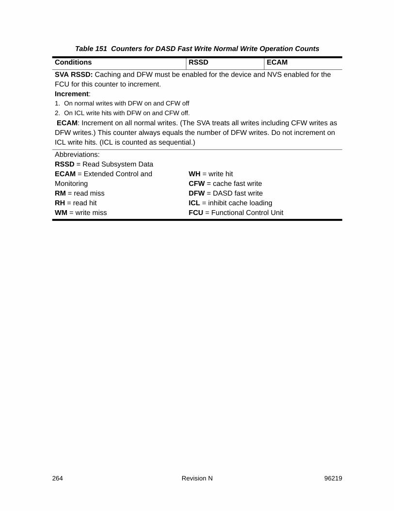
264 Revision N 96219
SVA RSSD: Caching and DFW must be enabled for the device and NVS enabled for the FCU for this counter to increment. Increment:1. On normal writes with DFW on and CFW off2. On ICL write hits with DFW on and CFW off. ECAM: Increment on all normal writes. (The SVA treats all writes including CFW writes as DFW writes.) This counter always equals the number of DFW writes. Do not increment on ICL write hits. (ICL is counted as sequential.)
Abbreviations:RSSD = Read Subsystem DataECAM = Extended Control and MonitoringRM = read missRH = read hitWM = write miss
WH = write hitCFW = cache fast writeDFW = DASD fast writeICL = inhibit cache loadingFCU = Functional Control Unit
Table 151 Counters for DASD Fast Write Normal Write Operation Counts
Conditions RSSD ECAM

96219 Revision N 265
DASD Fast Write Sequential Write Operation CountsBytes 80 through 83 of the subsystem data contains the counter for the number of DASD fast write sequential write operation counts. The following table describes when this counter is updated and when the corresponding ECAM counter is updated.
Table 152 Counters for DASD Fast Write Sequential Write Operation Counts
Conditions RSSD ECAMSequential, CFW off, DFW off RM RH WM WH RM RH WM WH
Sequential, CFW off, DFW on and enabled and NVS enabled
X X
Sequential, CFW off, DFW on and disable or NVS disabled
X X X X
Sequential, CFW on, DFW off X X
Sequential, CFW on, DFW on X X
Bypass, CFW off, DFW off X X
Bypass, CFW off, DFW on X X
Bypass, CFW on, DFW off X X
Bypass, CFW on, DFW on X X
ICL, CFW off, DFW off X X
ICL, CFW off, DFW on X X
ICL, CFW on, DFW off X X
ICL, CFW on, DFW on X X
SVA RSSD: Caching and DFW must be enabled for the device and NVS enabled for the FCU for this counter to increment. Increment on sequential writes with DFW on and CFW off.ECAM: Increment on all sequential, bypass, and ICL writes.
Abbreviations:RSSD = Read Subsystem DataECAM = Extended Control and MonitoringRM = read missRH = read hitWM = write miss
WH = write hitCFW = cache fast writeDFW = DASD fast writeICL = inhibit cache loadingFCU = Functional Control Unit

266 Revision N 96219


SUN™ THE NETWORK IS THE COMPUTER ©2006 Sun Microsystems, Inc. All rights reserved. Sun, Sun Microsystems, and the Sun logo are trademarks or registered trademarks of Sun Microsystems, Inc. in theUnited States and other countries.
Sun Microsystems, Inc. 4150 Network Circle, Santa Clara, CA 95054 USA Phone 1-650-960-1300 or 1-800-555-9SUN Web sun.com
ARGENTINA: 5411-4317-5636 • AUSTRALIA: 1-800-550-786 • AUSTRIA: 43-1-601-26-0 • BALKANS: 301-6188-111 • BELGIUM: 32 2-704 89 83 • BRAZIL: 55-11-51872100 • BRUNEI: 65-216-8333 • CANADA: 1-800-422-8020 (GENERAL); 416-964-2001 (LEARNING MANAGEMENT SYSTEM SALES,TORONTO) • CHILE: 562-372-4500 • COLOMBIA: 571-629-2323CZECH REPUBLIC: 420 2 33009311 • DENMARK: 45 4556 5040 • EGYPT: 00 202 570 9442 • FINLAND: 358-9-525-561 • FRANCE: 33-1-41-33-17-17 • GERMANY: 49-89-460-08-2788 • GREECE: 30-01-6188101 • HONG KONG: 852-2877-7077 • HUNGARY: 361-202-4415 • INDIA: 91-80-229-8989 • INDONESIA: 65-216-8333 • IRELAND: 353-1-668-4377ISRAEL: 972-9-9710500 • ITALY: 39-02-9259511 • JAPAN: 81-3-5779-1820 • KOREA: 82-2-3453-6602 • MALAYSIA: 603-2116-1887 • MIDDLE EAST: 00 9714 3366333 • MEXICO: 525-261-0344 • NETHERLANDS: 31-33-4515200 • NEW ZEALAND: 0800-786-338 • NORTH WEST AFRICA: 00 9714 3366333 • NORWAY: FROM NORWAY: 47-22023950, TO NORWAY:47-23369650 • PAKISTAN: 00-9714-3366333 • PEOPLE'S REPUBLIC OF CHINA: 8610-6803-5588 • PHILIPPINES: 632-885-7867 • POLAND: 48-22-8747848 • PORTUGAL: 351-21-413-4000 • RUSSIA: 7-095-935-8411 • SAUDI ARABIA: 00 9714 3366333 • SINGAPORE: 65-216-8300 • SOUTH AFRICA: 27-11-256-6300 • SPAIN: 34-902-210-412 • SRI LANKA:65-2168333 • SWEDEN: 46-8-631 22 00 • SWITZERLAND: 41-1-908-90-50 (GERMAN) 41-22-999-0444 (FRENCH) • TAIWAN: 886-2-25185735 • THAILAND: 662-344-6855 • TURKEY: 90 212 335 22 00 • UNITED KINGDOM: 44-1276-416-520 • UNITED STATES: 1-800-422-8020 • VENEZUELA: 582-905-3800 • VIETNAM: 65-216-8333 • WORLDWIDE
HEADQUARTERS: 1-650-960-1300