StorageTekâ„¢ Shared Virtual Array (SVA) - Oracle Documentation
142
StorageTek™ Shared Virtual Array (SVA) V2X/V2X2 Operations and Recovery Part Number : 96217 Revision N
Transcript of StorageTekâ„¢ Shared Virtual Array (SVA) - Oracle Documentation

StorageTek™Shared Virtual Array (SVA)
V2X/V2X2 Operations and Recovery
Part Number : 96217Revision N


StorageTek™ Shared Virtual Array (SVA)V2X/V2X2Operations and Recovery
Copyright 2006 Sun Microsystems, Inc., 4150 Network Circle, Santa Clara, California 95054, U.S.A. All rights reserved.
Sun Microsystems, Inc. has intellectual property rights relating to technology that is described in this document. In particular, and without limitation, these intellectual property rights might include one or more of the U.S. patents listed at http://www.sun.com/patents and one or more additional patents or pending patent applications in the U.S. and in other countries.
This document and the product to which it pertains are distributed under licenses restricting their use, copying, distribution, and decompilation. No part of the product or of this document might be reproduced in any form by any means without prior written authorization of Sun and its licensors, if any.
Third-party software, including font technology, is copyrighted and licensed from Sun suppliers.
Parts of the product might be derived from Berkeley BSD systems, licensed from the University of California. UNIX is a registered trademark in the U.S. and in other countries, exclusively licensed through X/Open Company, Ltd.
Sun, Sun Microsystems, the Sun logo, Java, AnswerBook2, docs.sun.com, StorageTek, StorageTek logo, VolSafe, and Solaris are trademarks or registered trademarks of Sun Microsystems, Inc. in the U.S. and in other countries.
All SPARC trademarks are used under license and are trademarks or registered trademarks of SPARC International, Inc. in the U.S. and in other countries. Products bearing SPARC trademarks are based upon an architecture developed by Sun Microsystems, Inc.
The OPEN LOOK and Sun™ Graphical User Interface was developed by Sun Microsystems, Inc. for its users and licensees. Sun acknowledges the pioneering efforts of Xerox in researching and developing the concept of visual or graphical user interfaces for the computer industry. Sun holds a non-exclusive license from Xerox to the Xerox Graphical User Interface, which license also covers Sun’s licensees who implement OPEN LOOK GUIs and otherwise comply with Sun’s written license agreements.
U.S. Government Rights—Commercial use. Government users are subject to the Sun Microsystems, Inc. standard license agreement and applicable provisions of the FAR and its supplements.
DOCUMENTATION IS PROVIDED "AS IS" AND ALL EXPRESS OR IMPLIED CONDITIONS, REPRESENTATIONS AND WARRANTIES, INCLUDING ANY IMPLIED WARRANTY OF MERCHANTABILITY, FITNESS FOR A PARTICULAR PURPOSE OR NON-INFRINGEMENT, ARE DISCLAIMED, EXCEPT TO THE EXTENT THAT SUCH DISCLAIMERS ARE HELD TO BE LEGALLY INVALID.
Copyright 2006 Sun Microsystems, Inc., 4150 Network Circle, Santa Clara, California 95054, Etats-Unis. Tous droits réservés.
Sun Microsystems, Inc. a les droits de propriété intellectuels relatants à la technologie qui est décrit dans ce document. En particulier, et sans la limitation, ces droits de propriété intellectuels peuvent inclure un ou plus des brevets américains énumérés à http://www.sun.com/patents et un ou les brevets plus supplémentaires ou les applications de brevet en attente dans les Etats-Unis et dans les autres pays.
Ce produit ou document est protégé par un copyright et distribué avec des licences qui en restreignent l’utilisation, la copie, la distribution, et la décompilation. Aucune partie de ce produit ou document ne peut être reproduite sous aucune forme, par quelque moyen que ce soit, sans l’autorisation préalable et écrite de Sun et de ses bailleurs de licence, s’il y en a.
Le logiciel détenu par des tiers, et qui comprend la technologie relative aux polices de caractères, est protégé par un copyright et licencié par des fournisseurs de Sun.
Des parties de ce produit pourront être dérivées des systèmes Berkeley BSD licenciés par l’Université de Californie. UNIX est une marque déposée aux Etats-Unis et dans d’autres pays et licenciée exclusivement par X/Open Company, Ltd.
Sun, Sun Microsystems, le logo Sun, Java, AnswerBook2, docs.sun.com StorageTek, StorageTek logo, VolSafe, et Solaris sont des marques de fabrique ou des marques déposées de Sun Microsystems, Inc. aux Etats-Unis et dans d’autres pays.
Toutes les marques SPARC sont utilisées sous licence et sont des marques de fabrique ou des marques déposées de SPARC International, Inc. aux Etats-Unis et dans d’autres pays. Les produits portant les marques SPARC sont basés sur une architecture développée par Sun Microsystems, Inc.
L’interface d’utilisation graphique OPEN LOOK et Sun™ a été développée par Sun Microsystems, Inc. pour ses utilisateurs et licenciés. Sun reconnaît les efforts de pionniers de Xerox pour la recherche et le développement du concept des interfaces d’utilisation visuelle ou graphique pour l’industrie de l’informatique. Sun détient une license non exclusive de Xerox sur l’interface d’utilisation graphique Xerox, cette licence couvrant également les licenciées de Sun qui mettent en place l’interface d ’utilisation graphique OPEN LOOK et qui en outre se conforment aux licences écrites de Sun.
LA DOCUMENTATION EST FOURNIE "EN L’ÉTAT" ET TOUTES AUTRES CONDITIONS, DECLARATIONS ET GARANTIES EXPRESSES OU TACITES SONT FORMELLEMENT EXCLUES, DANS LA MESURE AUTORISEE PAR LA LOI APPLICABLE, Y COMPRIS NOTAMMENT TOUTE GARANTIE IMPLICITE RELATIVE A LA QUALITE MARCHANDE, A L’APTITUDE A UNE UTILISATION PARTICULIERE OU A L’ABSENCE DE CONTREFAÇON.
We welcome your feedback. Please contact the Sun Learning Solutions Feedback System at:[email protected]
Global Learning Solutions Sun Microsystems, Inc. One StorageTek Drive Louisville, CO 80028-3256 USA
Please include the publication name, part number, and edition number in your correspondence if they are available. This expedites our response.
PleaseRecycle
96217 Revision N 5
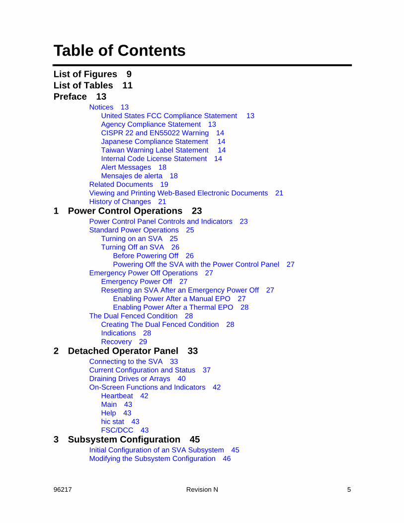
Table of ContentsList of Figures 9List of Tables 11Preface 13
Notices 13United States FCC Compliance Statement 13Agency Compliance Statement 13CISPR 22 and EN55022 Warning 14Japanese Compliance Statement 14Taiwan Warning Label Statement 14Internal Code License Statement 14Alert Messages 18Mensajes de alerta 18
Related Documents 19Viewing and Printing Web-Based Electronic Documents 21History of Changes 21
1 Power Control Operations 23Power Control Panel Controls and Indicators 23Standard Power Operations 25
Turning on an SVA 25Turning Off an SVA 26
Before Powering Off 26Powering Off the SVA with the Power Control Panel 27
Emergency Power Off Operations 27Emergency Power Off 27Resetting an SVA After an Emergency Power Off 27
Enabling Power After a Manual EPO 27Enabling Power After a Thermal EPO 28
The Dual Fenced Condition 28Creating The Dual Fenced Condition 28Indications 28Recovery 29
2 Detached Operator Panel 33Connecting to the SVA 33Current Configuration and Status 37Draining Drives or Arrays 40On-Screen Functions and Indicators 42
Heartbeat 42Main 43Help 43hic stat 43FSC/DCC 43
3 Subsystem Configuration 45Initial Configuration of an SVA Subsystem 45Modifying the Subsystem Configuration 46
6 Revision N 96217
Verifying the Current Release Level 46Current Status of the IML 47Changing Virtual Control Unit ID Numbers 48Correcting the Time and Date 48Changing Device Configurations 48
Subsystem Access Passwords 50Customer Logon Password 51CSE Logon Password 51CSRC Connection Allow/Disallow 51Changing Passwords 52
Viewing Operations 53Viewing the Subsystem Availability 53Viewing the Status of the FRU Configuration 54
Drain Operations 55Other Configuration Alterations 57
4 Error Recovery Actions 59General Operator Error Recovery Actions 59FSC/DCC Lookup 59Low Capacity FSC 3E41 Messages 60PPRC Secondary Devices Recovery 62
5 Exception Conditions 67Fencing 67Data Assurance Check Mode 67Pinned Data 68Exception Reporting 68
EREP Exception Reporting 68Using SIMs 68Establishing SIM Handling Procedures 69
Disk Array Recovery 70Recovery Procedure 70Recovery Time Estimate 71
A Drive Module Status 73B Service Information Messages 75
SIM Overview 75SIM Alert Message Formats 76SIM Reference Codes (SIM REFCODE) 78SIM ALERT Severity Levels 79
SIM Logging and Reporting 80SIM Severity Reporting Option 80Machine-Initiated Maintenance (MIM) 81SVA Generated SIMs and MIMs 81
C Configuration Terms Defined 85D Virtual Initialization Program 91
Overview 91VIP Menu Tree 92VIP Screens 93

96217 Revision N 7
On-Screen Functions and Indicators 93Heartbeat 93Main 93Help 93hic stat 93FSC/DCC 93Tool Bar on the Left Side 94
VIP Main Menu 94System Configuration and Status 95Maintenance and System Debug 96
System Initialization 97FRU ID Menu 99Write ISP PROM VIP 100Write ISP PROM SIML 101EC Upgrade 102Drive Reconstruction Menu 105Switch ISP Master 110Delete Installed Options 111Delete Corrupted DBs in all SRLs 112Reset Frame S/N in Boot Blocks to 0 113Unfence Hard Drive 114
Select Software Release Level 115Directory Display 116Diagnostic Functions 118
Volume Verification 119Create pHILE Control Files 120Check pHILE Volumes 121Maintenance Bus Diagnostic Menu 122
State Save Functions 128Find All State Saves 129Find All IUP State Saves 130Find All ISP State Saves 131Initialize All State Saves 132Initialize All IUP State Saves 133Initialize ISP State Saves 134
IML the ISP 135E Dual Fenced Condition 137
Indications 137Recovery 137

8 Revision N 96217

96217 Revision N 9
List of Figures
Figure 1 Power Control Panel 24Figure 2 VIP Dual Fenced Condition Warning 29Figure 3 Volume Verification Menu 30Figure 4 Volume Verification Menu with no faults found screen 31Figure 5 Connection Screen 33Figure 6 Main Menu and Logon Screen 34Figure 7 Password Override Screen 35Figure 8 Customer Main Menu (Logged In) 36Figure 9 Configuration / Status Menu Screen 37Figure 10 Subsystem Configuration and Status Screen 38Figure 11 Set Date and Time Screen 39Figure 12 Drain Drive Request Screen (Upper Half) 40Figure 13 Drain Drive Request Screen (Lower Half) 41Figure 14 Drain Drive Request Warning Screen 42Figure 15 Subsystem Configuration and Status 47Figure 16 Virtual Unit Data Screen(Upper half) 49Figure 17 Virtual Unit Configuration Screen 50Figure 18 Access Control Screen 52Figure 19 Change Customer Password Screen 53Figure 20 Subsystem Availability Screen 54Figure 21 FRU Status Screen 55Figure 22 Drain Request Page Screen (upper part) 56Figure 23 Drain Request Page Screen (lower part) 57Figure 24 FSC/DCC Lookup Screen with FSC3a41 Showing. 60Figure 25 Terminate PPRC Screen 63Figure 26 PPRC Termination Warning (upper half) 64Figure 27 PPRC Termination Warning (lower half) 65Figure 28 SIM Alert Message Format 77Figure 29 An Example MVS SIM Alert Message 77Figure 30 An Example VM/SP and VM/SP HPO SIM Alert Message 77Figure 31 VIP Menu Tree 92Figure 32 Main VIP Screen 94Figure 33 VIP System Configuration and Status Screen 95Figure 34 VIP Maintenance and System Debug Screen 96Figure 35 System Initialization Screen 97Figure 36 System Initialization Complete Screen 98Figure 37 FRU ID Menu Screen 99Figure 38 Write ISP PROM VIP Screen 100Figure 39 Write ISP PROM SIML Screen 101Figure 40 EC Upgrade Screen 102Figure 41 EC Upgrade Second Screen 103
96217 Revision N 10
Figure 42 EC Upgrade File Transfer in Progress 104Figure 43 Drive Reconstruction Menu Screen 105Figure 44 Drive Fenced Screen 106Figure 45 Successful Drive Reconstruction Screen 107Figure 46 Drive Reconstruction Failure Screen 108Figure 47 Connection During Drive Reconstruction Screen 109Figure 48 Switch ISP Master Screen 110Figure 49 Delete Installed Options Screen 111Figure 50 Delete Corrupted Databases in all SRLs Screen 112Figure 51 Reset Frame S/N in Boot Blocks to 0 Screen 113Figure 52 Unfence Hard Drive Screen 114Figure 53 VIP Select Software Release Level Screen 115Figure 54 VIP Directory Display Screen 116Figure 55 Display Directory Screen Example 117Figure 56 VIP Diagnostic Menu Screen 118Figure 57 Volume Verification Screen 119Figure 58 Create pHILE Control Files Screen 120Figure 59 Check pHILE Volumes Screen 121Figure 60 Maintenance Bus Diagnostic Menu Screen 122Figure 61 Command Sent to Server Screen 123Figure 62 Test Running Screen 124Figure 63 Test Pass Complete Screen 125Figure 64 Command in Progress Screen 126Figure 65 Test Set to Looping Forever Screen 127Figure 66 VIP State Save Menu Screen 128Figure 67 Find All State Saves Screen 129Figure 68 Find All IUP State Saves Screen 130Figure 69 Find All ISP State Saves Screen 131Figure 70 Initialize All State Saves Screen 132Figure 71 Initialize IUP State Saves Screen 133Figure 72 Initialize ISP State Saves Screen 134Figure 73 VIP IML Selection Screen 135Figure 74 VIP Dual Fenced Condition Warning 138Figure 75 Volume Verification Menu 138Figure 76 Volume Verification Menu with no faults found screen 139
96217 Revision N 11
List of Tables
Table 1 Power Control Panel 25Table 2 Drive Module Status Descriptions 73Table 3 SIM Alert Messages 77Table 4 SIM Severity Levels 79Table 5 System-Generated SIM and MIM Events 82Table 6 Configuration Terms 85

12 Revision N 96217

96217 Revision N 13
Preface
NoticesPlease read the following compliance and warning statements for this product.
Caution: Potential equipment damage: Cables that connect peripherals must be shielded and grounded; refer to cable descriptions in the instruction manuals. Operation of this
equipment with cables that are not shielded and not correctly grounded might result in interference to radio and TV reception. Changes or modifications to this equipment that are not expressly approved in advance by Sun Microsystems Inc. will void the warranty. In addition, changes or modifications to this equipment might cause it to create harmful interference.
United States FCC Compliance Statement The following compliance statement pertains to Federal Communications Commission Rules 47 CFR 15.105:Note: This equipment has been tested and found to comply with the limits
for a Class A digital device pursuant to part 15 of the FCC Rules. These limits are designed to provide reasonable protection against harmful interference when the equipment is operated in a commercial environment. This equipment generates, uses, and can radiate radio frequency energy and, if not installed and used in accordance with the instruction manual, may cause harmful interference to radio communications. Operation of this equipment in a residential area is likely to cause harmful interference in which case the user will be required to correct the interference at his or her own expense.
Agency Compliance StatementThe SVA complies with the following agencies: UL–Recognized Component by Underwriters Laboratories Inc. to Standard UL 60950, Information Technology Equipment. CE–Mark to show compliance to European Union Directives (European Union: Safety & EMC).

14 Revision N 96217
CISPR 22 and EN55022 WarningThis is a Class A product. In a domestic environment this product may cause radio interference in which case the user may be required to take adequate measures.
Japanese Compliance Statement The following compliance statement in Japanese pertains to VCCI EMI regulations:
English translation: This is a Class A product based on the Technical Requirement of the Voluntary Control Council for Interference by Information Technology (VCCI). In a domestic environment, this product may cause radio interference, in which case the user may be required to take corrective actions.
Taiwan Warning Label Statement The following warning label statement (in Kanji) pertains to BSMI regulations in Taiwan, R.O.C.:
English translation: This is a Class A product. In a domestic environment, this product may cause radio interference, in which case, the user may be required to take adequate measures.
Internal Code License StatementThe following is the Internal Code License Agreement from Sun Microsystems Inc.:NOTICEINTERNAL CODE LICENSEPLEASE READ THIS NOTICE CAREFULLY BEFORE INSTALLING AND OPERATING THIS EQUIPMENT. THIS NOTICE IS A LEGAL AGREEMENT BETWEEN YOU (EITHER AN INDIVIDUAL OR

96217 Revision N 15
ENTITY), THE END USER, AND STORAGE TECHNOLOGY CORPORATION (“Sun Microsystems”), THE MANUFACTURER OF THE EQUIPMENT. BY OPENING THE PACKAGE AND ACCEPTING AND USING ANY UNIT OF EQUIPMENT DESCRIBED IN THIS DOCUMENT, YOU AGREE TO BECOME BOUND BY THE TERMS OF THIS AGREEMENT. IF YOU DO NOT AGREE WITH THE TERMS OF THIS AGREEMENT, DO NOT OPEN THE PACKAGE AND USE THE EQUIPMENT. IF YOU DO NOT HAVE THE AUTHORITY TO BIND YOUR COMPANY, DO NOT OPEN THE PACKAGE AND USE THE EQUIPMENT. IF YOU HAVE ANY QUESTIONS, CONTACT THE AUTHORIZED SUN MICROSYSTEMS INC. DISTRIBUTOR OR RESELLER FROM WHOM YOU ACQUIRED THIS EQUIPMENT. IF THE EQUIPMENT WAS OBTAINED BY YOU DIRECTLY FROM SUN MICROSYSTEMS INC., CONTACT YOUR SUN MICROSYSTEMS INC. REPRESENTATIVE.
1. Definitions: The following terms are defined as follows:
A. “Derivative works” are defined as works based upon one or more preexisting works, such as a translation or a musical arrangement, or any other form in which a work may be recast, transformed, or adapted. A work consisting of editorial revision, annotations, elaboration, or other modifications which, as a whole, represent an original work of authorship, is a Derivative work.
B. “Internal Code” is Microcode that (i) is an integral part of Equipment, (ii) is required by such Equipment to perform its data storage and retrieval functions, and (iii) executes below the user interface of such Equipment. Internal code does not include other Microcode or software, including data files, which may reside or execute in or be used by or in connection with such Equipment, including, without limitation, Maintenance Code.
C. “Maintenance Code” is defined as Microcode and other software, including data files, which may reside or execute in or be used by or in connection with Equipment, and which detects, records, displays, and/or analyzes malfunctions in the Equipment.
D. “Microcode” is defined as a set of instructions (software) that is either imbedded into or is to be loaded into the Equipment and executes below the external user interface of such Equipment. Microcode includes both Internal Code and Maintenance Code,

16 Revision N 96217
and may be in magnetic or other storage media, integrated circuitry, or other media.
2. The Equipment you have acquired by purchase or lease is manufactured by or for Sun Microsystems Inc. and contains Microcode. By accepting and operating this Equipment, you acknowledge that Sun Microsystems Inc. or its licensor(s) retain(s) ownership of all Microcode, as well as all copies thereof, that may execute in or be used in the operation or servicing of the Equipment and that such Microcode is copyrighted by Sun Microsystems Inc. or its licensor(s).
3. Sun Microsystems Inc. hereby grants you, the end user of the Equipment, a personal, nontransferable (except as permitted in the transfer terms below), nonexclusive license to use each copy of the Internal Code (or any replacement provided by Sun Microsystems Inc. or your authorized Sun Microsystems Inc. distributor or reseller) which license authorizes you, the end user, to execute the Internal Code solely to enable the specific unit of Equipment for which the copy of Internal Code is provided to perform its data storage and retrieval functions in accordance with Sun Microsystems Inc.’s (or its licensor’s) official published specifications.
4. Your license is limited to the use of the Internal Code as set forth. You may not use the Internal Code for any other purpose. You may not, for example, do any of the following:
(i) access, copy, display, print, adapt, alter, modify, patch, prepare Derivative works of, transfer, or distribute (electronically or otherwise) or otherwise use the Internal Code;
(ii) reverse assemble, decode, translate, decompile, or otherwise reverse engineer the Internal Code (except as decompilation may be expressly permitted under applicable European law solely for the purpose of gaining information that will allow interoperability when such information is not otherwise readily available); or
(iii) sublicense, assign, or lease the Internal Code or permit another person to use such Internal Code, or any copy of it.
5. Nothing in the license set forth above or in this entire Notice shall convey, in any manner, to you any license to or title to or other right to use any Maintenance code, or any copy of such Maintenance Code. Maintenance Code and Sun Microsystems Inc.’s service
96217 Revision N 17
tools and manuals may be kept at your premises, or they may be supplied with a unit of Equipment sent to you and/or included on the same media as Internal Code, but they are to be used only by Sun Microsystems Inc.’s customer service personnel or those of an entity licensed by Sun Microsystems Inc., all rights in and to such Maintenance Code, service tools and manuals being reserved by Sun Microsystems Inc. or its licensors. You agree that you shall not use or attempt to use the Maintenance Code or permit any other third party to use and access such Maintenance Code.
You, the end user, agree to take all appropriate steps to ensure that all of your obligations set forth in this Notice are extended to any third party having access to the Equipmen
6. You may transfer possession of the Internal Code to another party only with the transfer of the Equipment on which its use is authorized, and your license to use the Internal Code is discontinued when you are no longer an owner or a rightful possessor of the Equipment. You must give such transferee all copies of the Internal Code for the transferred Equipment that are in your possession, along with a copy of all provisions of this Notice.
Any such transfer by you is automatically (without further action on the part of either party) expressly subject to all the terms and conditions of this Notice passing in full to the party to whom such Equipment is transferred, and such transferee accepts the provisions of this license by initial use of the Internal Code. You cannot pass to the transferee of the Equipment any greater rights than granted under this Notice, and shall hold Sun Microsystems Inc. harmless from any claim to the contrary by your transferee or its successors or assigns. In addition, the terms and conditions of this Notice apply to any copies of Internal Code now in your possession or use or which you hereafter acquire from either Sun Microsystems Inc. or another party.
7. You acknowledge that copies of both Internal Code and Maintenance Code may be installed on the Equipment before shipment or included with the Equipment and other material shipped to you, all for the convenience of Sun Microsystems Inc.’s service personnel or service providers licensed by Sun Microsystems Inc., and that during the warranty period, if any, associated with the Equipment, and during periods in which the Equipment is covered under a maintenance contract with Sun

18 Revision N 96217
Microsystems Inc. or service providers licensed by Sun Microsystems Inc., both Internal Code and Maintenance Code may reside and be executed in or used in connection with such Equipment, and you agree that no rights to Maintenance Code are conferred upon you by such facts.
Sun Microsystems Inc. or the licensed service provider may keep Maintenance Code and service tools and manuals on your premises but they are to be used only by Sun Microsystems Inc.’s customer service personnel or those of service providers licensed by Sun Microsystems Inc.. You further agree that upon (i) any termination of such warranty period or maintenance contract period; or (ii) transfer of possession of the Equipment to another party, Sun Microsystems Inc. and its authorized service providers shall have the right with respect to the affected Equipment to remove all service tools and manuals and to remove or disable all Maintenance Code and/or replace Microcode which includes both Internal Code and Maintenance Code with Microcode that consists only of Internal Code.
Alert MessagesAlert messages call your attention to information that is especially important or that has a unique relationship to the main text or graphic.Note: A note provides additional information that is of special interest. A
note might point out exceptions to rules or procedures. A note usually, but not always, follows the information to which it pertains.
Caution: informs you of conditions that might result in damage to hardware, corruption of data, or corruption of application software. A caution always precedes the
information to which it pertains.Warning:A warning alerts you to conditions that might result in long-term health problems, injury, or death. A warning always precedes the information to which it pertains.
Mensajes de alertaLos mensajes de alerta llaman la atención hacia información de especial importancia o que tiene una relación específica con el texto principal o los gráficos.Nota:Una nota expone información adicional que es de interés especial. Una nota puede señalar excepciones a las normas o procedimientos. Por lo general, aunque no siempre, las notas van después de la información a la que hacen referencia.

96217 Revision N 19
Precaución: Una precaución informa sobre situaciones que podrían conllevar daños del hardware, de los datos o del software de aplicación. Las precauciones van siempre antes de la información a la que hacen referencia.
Advertencia: Una advertencia llama la atención sobre condiciones que podrían conllevar problemas de salud crónicos, lesiones o muerte. Las advertencias van siempre antes de la información a la que hacen referencia.
Related DocumentsThe following publications comprise the SVA document set available to Sun Microsystems Inc. customers.Shared Virtual Array (SVA) SubsystemNote: The book part numbers changed. The old numbers are shown in parenthesis. • StorageTek Shared Virtual Array (SVA) V2X/V2X2 Introduction
96216 (MO9135)• StorageTek Shared Virtual Array (SVA) V2X/V2X2 Operation and
Recovery 96217 (MO9137) • StorageTek Shared Virtual Array (SVA) V2X/V2X2 Planning 96218
(MO9136) • StorageTek Shared Virtual Array (SVA) V2X/V2X2 Reference
96219 (MO9139) • StorageTek Shared Virtual Array (SVA) V2X/V2X2 System
Assurance 96220 (MO9138) • StorageTek Shared Virtual Array (SVA) V2X/V2X2 System
Assurance Tables 96223 (MO9169) • StorageTek Shared Virtual Array (SVA) V2X/V2X2 General
Information 96221 (MO9134)• StorageTek Shared Virtual Array (SVA) V2X/V2X2 Peer-to-Peer
Copy Configuration User’s Guide 96225 (MO9211)Shared Virtual Array Administrator (SVAA) for OS/390• SVAA for OS/390 Configuration and Administration PN 3112905xx• SVAA for OS/390 Reporting PN 3112906xx• SVAA for OS/390 Installation, Customization, and Maintenance PN
3112908xx• SVA SnapShot for OS/390 Installation, Customization, and
Maintenance PN 3112913xxShared Virtual Array Administrator (SVAA) for VM• SVAA for VM Configuration and Administration PN 3134629xx• SVAA for VM Reporting PN 3134630xx
20 Revision N 96217
• SVAA for VM Installation, Customization, and Maintenance PN 3134631xx
Shared Virtual Array Administrator (SVAA) for OS/390 and VM• SVAA for OS/390 and VM Messages and Codes PN 3112907xxShared Virtual Array Administrator (SVAA) for Solaris• SVAA for Solaris User’s Guide PN 3112909xx• SVAA for Solaris Messages PN 3112910xx• SVAA for Solaris Installation PN 3112911xx• SVAA for Solaris Quick Start Guide PN 3134509xx• SVAA for Solaris Command Quick Reference PN 3134119xxShared Virtual Array Administrator (SVAA) for HP-UX• SVAA for HP-UX User’s Guide PN 3134257xx• SVAA for HP-UX Messages PN 3134244xx• SVAA for HP-UX Installation PN 3134254xx• SVAA for HP-UX Quick Start Guide PN 3134512xx• SVAA for HP-UX Command Quick Reference PN 3134253xxShared Virtual Array Administrator (SVAA) for AIX• SVAA for AIX User’s Guide PN 3134602xx• SVAA for AIX Messages PN 3134600xx• SVAA for AIX Installation PN 3134599xx• SVAA for AIX Quick Start Guide PN 3134601xx• SVAA for AIX Command Quick Reference PN 3134598xxShared Virtual Array Administrator (SVAA) for Windows 2000 Server and Windows NT Server• SVAA for Windows 2000 Server and Windows NT Server User’s
Guide PN 3134573xx• SVAA for Windows 2000 Server and Windows NT Server
Messages PN 3134571xx• SVAA for Windows 2000 Server and Windows NT Server
Installation PN 3134570xx• SVAA for Windows 2000 Server and Windows NT Server Quick
Start Guide PN 3134572xx• SVAA for Windows 2000 Server and Windows NT Server
Command Quick Reference PN 3134569xxShared Virtual Array Console (SVAC) for Windows NT• SVAC for Windows NT Quick Start Guide PN 3112993xxOther Documents• Peer to Peer Remote Copy Configuration Guide MP4007x• Planning For IBM Remote Copy SG24-2595-xx (IBM document)
96217 Revision N 21
• Remote Copy Administrator’s Guide and Reference SC35-0169-xx (IBM document)
Viewing and Printing Web-Based Electronic DocumentsPublications listed in “Related Documents” can be viewed and printed from the Sun Microsystems Inc. Customer Resource Center (CRC) Web site at:http://www.support.storagetek.com
History of ChangesRev A – Initial release. September, 2002.Rev B – Second release. December, 2002
Minor changes involved edits and corrections. Major changes include:
- Added “Low Capacity FSC 3E41 Messages” section to chapter four.
Rev C – Third release. March, 2003. Minor changes involving edits and corrections.Rev D – Fourth release. March, 2003. Minor changes involving edits and corrections.Rev E – Fifth release. May, 2003. Minor changes involving edits and corrections.Rev F – Sixth release. December, 2003. Minor changes involving edits and corrections.Rev G – Seventh release. April, 2004. Minor changes involving edits and corrections.Rev H – Eighth release. February, 2005. Minor changes involving edits and corrections
Major changes include:- Changed document part number- Changed Danger to Warning
Rev J – Ninth release. December 2005. Minor changes and corrections. Rev K – Tenth release. May 2006. Minor changes and correstions. Major changes involve:
- Adding the chapter “Detached Operator Panel” on page 25. - Removed the chapter on system configuration by means of the
22 Revision N 96217
local operator panel.- Add an appendix for the Virtual Initialization Program.
• Added “Dual Fenced Condition” on page 137.Rev L – Eleventh release. June 2006. Minor changes and edits.Rev M – Twelfth release. Late July 2006. Minor changes and corrections. Rev N – Thirteenth release. November 2006. Minor changes and corrections in addition to:• Removed incorrect PAV information• Removed incorrect IFC card information• Added List of Tables and List of Figures pages• Replaced dual fenced condition recovery procedure.

96217 Revision N 23
1Power Control Operations
Power Control Panel Controls and IndicatorsThe V2X/V2X2™ has a power control panel recessed into the right front door of the cabinet. The power control panel contains buttons and switches to select power control states and indicators to show the unit’s power status. The following figure illustrates the SVA’s power control panel. Table 1 on page 25 provides a brief functional description of the controls and indicators found on the power control panel.

24 Revision N 96217
Figure 1 Power Control Panel
1 2
3
5
6
8
C95003
4
7
RESET/RUN CUSTOMER/CSE
POWER CHECK
POWER
SEQUENCE
COMPLETE
POWER ON

96217 Revision N 25
Standard Power OperationsTurning on an SVA
1. Verify that the red UNIT EMERGENCY button on the power control panel is set to 1 (Out) position.
- A UNIT EMERGENCY button is in the 1 position when the red button stands out from the frame.
- A UNIT EMERGENCY button is in the 0 position when the red button is flush with the frame.
Table 1 Power Control Panel
Figure 1 Reference
Switch or Indicator Function
1 UNIT EMERGENCY Switch (EPO)
Depressing this switch (0 position) instantly disables subsystem power beyond PDUs. Setting switch to the out (1) position allows subsystem power to be enabled when POWER ENABLE switch is pressed. A battery backup system protects nonvolatile cache data (NVS) during EPO.
2 POWER ON Indicator
Lights green if 5V DC is present and within spec at C3 motherboard.
3 POWER SEQUENCE COMPLETE Indicator
Microcode-controlled; lights green after subsystem verifies that all power checks completed error-free during ‘power on’ sequence.
4 POWER ENABLE Switch
Setting switch to OFF (0) initiates a Controlled Power Down (CPD) of subsystem. Setting switch to ON (1) enables subsystem power.
5 POWER CHECK Indicator
Microcode-controlled; lights amber if subsystem power checks do not complete error-free during ‘power on’ sequence.
6 ISP Drive LEDs Light green when ISP drives are active (visible from the right side).
7 RUN/RESET Switch
Resets subsystem after thermal EPO. Switch is accessible only if front doors of unit are unlocked.
8 CSE/CUSTOMER Switch
Determines how subsystem power is reset after EPO. Switch is set by service representative at installation and is accessible only if front doors of unit are unlocked.
26 Revision N 96217
2. If a controlled power down was initiated at the Local Operator Panel, set the POWER ENABLE switch to the 0 (OFF) position and wait a few seconds before continuing.
3. Set the POWER ENABLE button on the Controller’s power control panel to 1 (ON). The following sequence takes place:
Note: With the doors closed, some of these items are not noticeable.- The POWER ON indicator lights on the power control panel
and power distribution units.- All array and controller impellers start spinning.- After 3 to 5 minutes these conditions start to occur:
- The local operator panel activates- Amber LEDs (present on some FRUs) light up- Array drives sequence on; an amber LED lights on each,
then goes out as the drive becomes ready; when a drive is ready, its green LED lights
- The support facility starts the IML/test verification procedure
- Amber LEDs (present on some FRUs) go off as the FRU is validated
- After the support facility verifies successful completion of the ‘power-on’ sequence, the POWER SEQUENCE COMPLETE indicator lights.
Note: IML can take 1 hour or longer, based on cache size and the number of arrays. When IML finishes, the “Subsystem Main Menu (SS01)” screen is displayed. The message ‘Full Box IML Complete’ is displayed on the upper ‘Status’ line, then is replaced by the message ‘Battery Test Complete’.
4. Mainframe: The operator may vary online all channels and functional devices between the subsystem and host system(s).
Caution: Potential Performance Loss - The SVA does not support varying a CHPID online during a check0/warm start. The user receives the message "DYNAMIC PATH
NOT OPERATIONAL” at the console. Open Systems: The operator may now mount all file systems connected to the SVA and start applications as required.
Turning Off an SVABefore Powering Off
Mainframe:

96217 Revision N 27
1. At the host console, vary all of the addresses to the Disk Array Controller offline.
2. At the host console, vary all of the channels to the Disk Array Controller offline.
Open Systems:
1. Close all applications using the SVA.
2. Un-mount all file systems using the SVA.
After doing either mainframe/open systems pre-power down procedures, either use the Power Control Panel or the LOP to turn off the SVA.
Powering Off the SVA with the Power Control PanelSet the POWER ENABLE button on the SVA’s power control panel to 0 (OFF). The Power ON indicator on the SVA’s power control panel goes out.Note: Standard power off does not shut down the subsystem immediately.
How long it takes depends on the amount of system activity and quiesce/cleanup needed.
Emergency Power Off OperationsThis is also known as an emergency power off, or EPO.
Emergency Power OffTo turn off an SVA Controller in an emergency:
1. Locate the red UNIT EMERGENCY button on the unit’s power control panel.
2. Lift the clear plastic guard, and press the UNIT EMERGENCY button. The unit powers down in the fastest possible sequence without compromising data integrity, and the Power On indicator goes out.
Resetting an SVA After an Emergency Power OffEnabling Power After a Manual EPO
Find the CUSTOMER/CSE switch on the bottom of the power control panel, then:If the CSE/CUSTOMER switch is set to ‘CSE’: • set the CSE/CUSTOMER to ‘CUSTOMER’, • then set the UNIT EMERGENCY switch to the 0 (OFF) position,• Then return the CSE/CUSTOMER switch to the ‘CUSTOMER’,
position,

28 Revision N 96217
• now initiate a normal power on sequence if that’s desired at this time.
If the CSE/CUSTOMER switch is set to ‘CUSTOMER’:• leave the CSE/CUSTOMER switch in the CUSTOMER position,• set the UNIT EMERGENCY switch to the 0 (OFF) position,• now initiate a normal power on sequence if that’s desired at this
time.
Enabling Power After a Thermal EPOA serious condition must be assumed to exist within the SVA. Contact your Sun Microsystems service representative to have that situation fixed before any attempt is made to reset the power.
The Dual Fenced ConditionIf one of the drives for the SVA’s internal processor cards is “fenced” or otherwise unusable and the usable drive is in the middle of a write operation and there is a complete loss of power to the SVA or the EPO button is pressed, it renders the last usable drive as “fenced.” When power is restored, the V2X/V2X2 finds no usable drives from which to IML.Note: These drives are not used for customer data. Customer data is not
impacted by this condition.
Creating The Dual Fenced ConditionThis dual “fenced” condition is easily created by using the EPO button to shut down the SVA during an IML. the SVA writes to the HD cards during an IML. Using the EPO button once during an IML could “fence” the first drive. Using the EPO button a second time, before the reconstruction of the first fenced drive is complete, could fence the second drive. Repeated customer power outages could create the same conditions.During a normal power down, the SVA finishes all write activity to the hard drives before finally shutting down power, thus avoiding this condition. It is only the sudden loss of power or the use of the EPO button that creates the conditions required to “fence” the drive(s).
IndicationsThis dual “fenced” condition is indicated at power on by the power up sequence stopping without the Power Complete LED illuminating and the LOP remaining blank.

96217 Revision N 29
RecoveryRecovery from the “dual fenced condition” is done with the VIP. Follow this procedure to correct the problem:
1. Reboot the SVA in VIP mode: this is done by holding the switch on the Faceplate Assembly in the VIP position, then pressing the power button.
2. Once VIP starts, there is a warning message superimposed over the main VIP screen indicating that there is a problem with a volume. This warning is shown in the following figure. Click on the Ok button.
Figure 2 VIP Dual Fenced Condition Warning

30 Revision N 96217
3. The Volume Verification Menu (shown in the following figure) displays.
Figure 3 Volume Verification Menu
4. The volume verification starts as shown in the previous figure. Once it is complete, it looks like the screen of the following figure. Examine that screen carefully. It either indicates no faults were found, or if there was a problem:
- the text of changes from “No faults were found” to one indicating a fault was found and fixed, or
- the text displays an indication that some non-fixable faults found.

96217 Revision N 31
Figure 4 Volume Verification Menu with no faults found screen
5. After the previous figure (screen) appears:
• If no faults were found, you may continue with normal operation – the subsystem may be IMLed in production mode.
• If fixable faults were found, (they were fixed automatically) the you may continue with normal operation – the subsystem would be IMLed in production mode (check to see if the subsystem fenced any drives after the IML completes).
• If non-fixable faults were found, you need to perform a system initialization.
Caution: Possible Performance Problem and Data Loss - If non-fixable faults were found, a service representative should be called to assist with restoring the system
correctly. This is not a minor problem!

32 Revision N 96217
96217 Revision N 33
2Detached Operator Panel
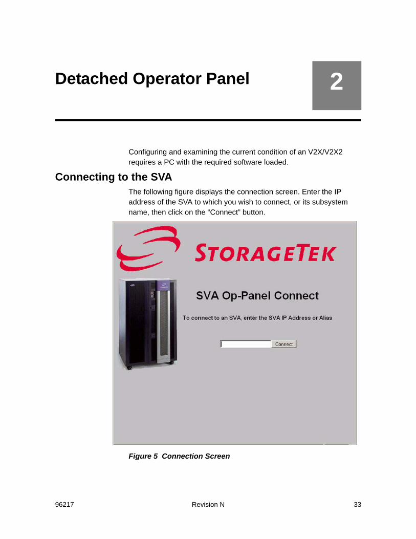
Configuring and examining the current condition of an V2X/V2X2 requires a PC with the required software loaded.
Connecting to the SVAThe following figure displays the connection screen. Enter the IP address of the SVA to which you wish to connect, or its subsystem name, then click on the “Connect” button.
Figure 5 Connection Screen

34 Revision N 96217
If the connection was successful, you are taken to the Main Menu and Logon Screen. This screen is shown in the following figure. Either choose a menu item or log onto the SVA for more options.
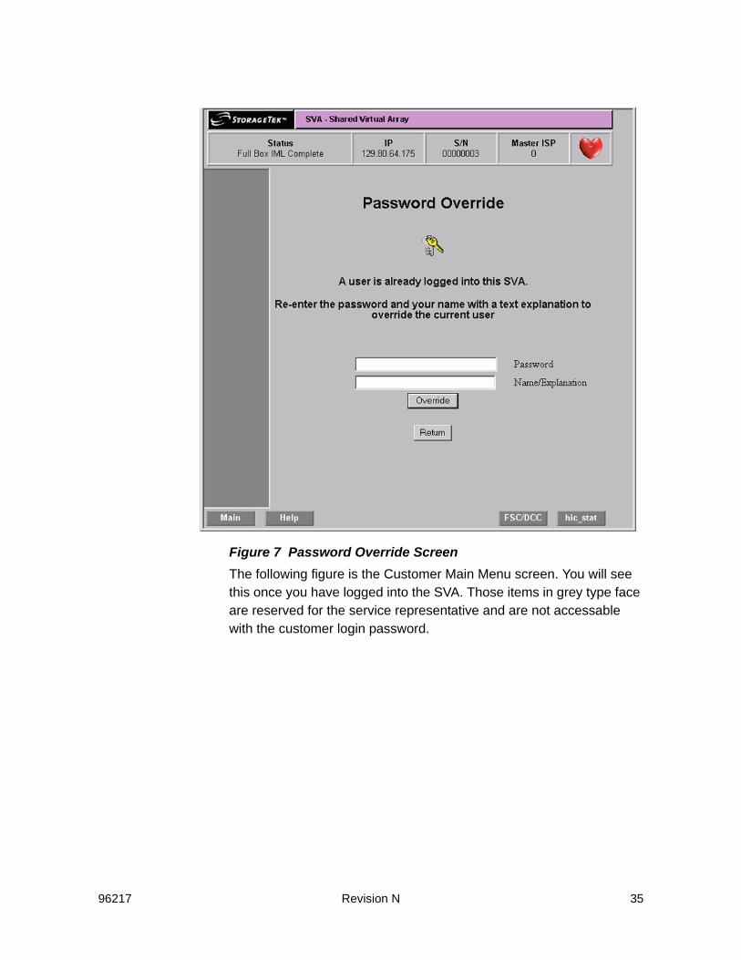
Figure 6 Main Menu and Logon ScreenIf you choose to log onto the SVA, enter your password and click on the “Logon” button.Note: Only one PC can be logged onto the SVA at a time. If a second PC
attempts to log onto the SVA, a logon override message appears. See Figure 7 on page 35. If you re-enter the password, you are removing the other PC’s access. There is a provision on that screen to enter an explanation in the event that you bumped someone off of the SVA and they tried to connect again while you were still logged into the SVA. When you log out, this explanation is removed.
96217 Revision N 35
Figure 7 Password Override ScreenThe following figure is the Customer Main Menu screen. You will see this once you have logged into the SVA. Those items in grey type face are reserved for the service representative and are not accessable with the customer login password.

36 Revision N 96217
Figure 8 Customer Main Menu (Logged In)
96217 Revision N 37
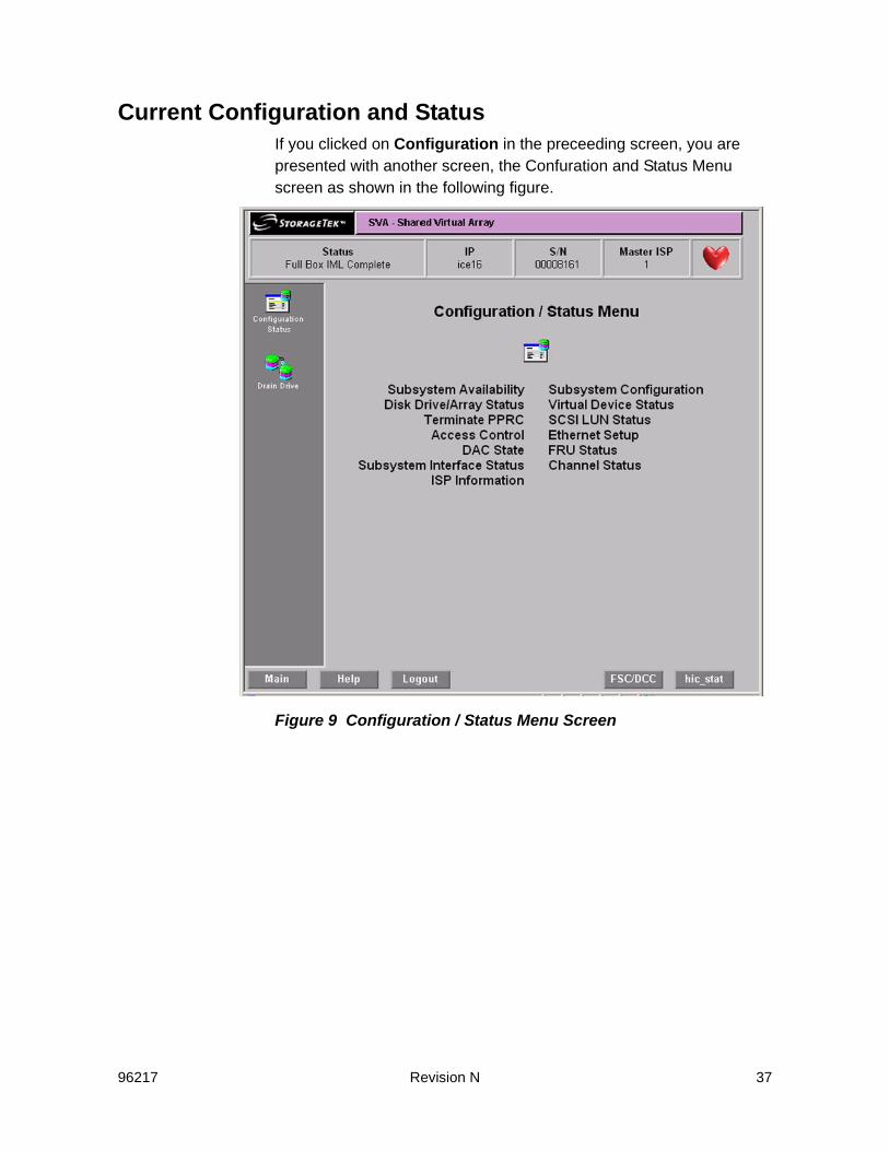
Current Configuration and StatusIf you clicked on Configuration in the preceeding screen, you are presented with another screen, the Confuration and Status Menu screen as shown in the following figure.
Figure 9 Configuration / Status Menu Screen

38 Revision N 96217
To view the SVA’s current configuration, click Subsystem Configuration. This presents the Subsystem Configuration and Status screen as shown in the following screen.
Figure 10 Subsystem Configuration and Status ScreenThe only items you can change on this screen are date and time. For all other changes, consult your service representative. In the preceeding figure in the options section, the green boxes with a white check mark are installed or enabled items. A red box with a white X in the center of it is used to indicate items that are not installed or not enabled.
96217 Revision N 39
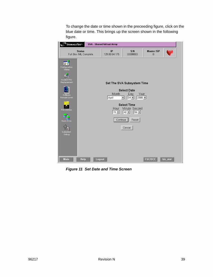
To change the date or time shown in the preceeding figure, click on the blue date or time. This brings up the screen shown in the following figure.
Figure 11 Set Date and Time Screen

40 Revision N 96217
Draining Drives or ArraysIn Figure 8 on page 36, if you click on the Drain Drive selection, you are presented with the following figure shown (the upper half of the screen) and Figure 13 on page 41 (the lower half of that screen).
Figure 12 Drain Drive Request Screen (Upper Half)Moving your cursor over a disk drive’s block causes a pop-up box to appear with information regarding that drive.
96217 Revision N 41
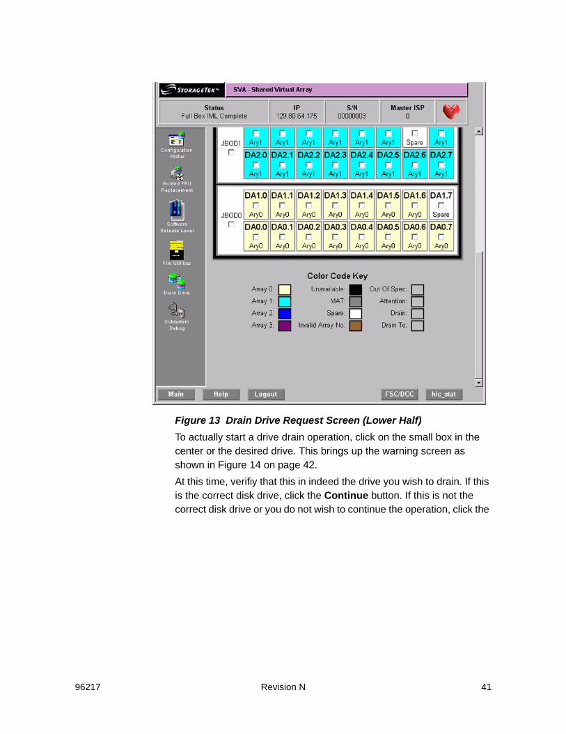
Figure 13 Drain Drive Request Screen (Lower Half)To actually start a drive drain operation, click on the small box in the center or the desired drive. This brings up the warning screen as shown in Figure 14 on page 42. At this time, verifiy that this in indeed the drive you wish to drain. If this is the correct disk drive, click the Continue button. If this is not the correct disk drive or you do not wish to continue the operation, click the
42 Revision N 96217
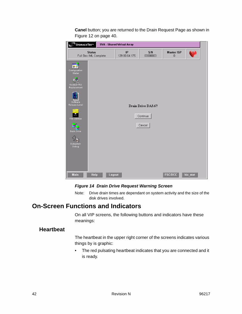
Canel button; you are returned to the Drain Request Page as shown in Figure 12 on page 40.
Figure 14 Drain Drive Request Warning ScreenNote: Drive drain times are dependant on system activity and the size of the
disk drives involved.
On-Screen Functions and IndicatorsOn all VIP screens, the following buttons and indicators have these meanings:
HeartbeatThe heartbeat in the upper right corner of the screens indicates various things by is graphic:• The red pulsating heartbeat indicates that you are connected and it
is ready.

96217 Revision N 43
• The red heart with the circle and diagonal line through it indicates that the connection to the V2X/V2X2 has been lost (even if only temporally as in when doing a re-boot).
• A disk drive replacing the heart with a percentage close to it indicates a drive rebuild is in progress and the percentage it has completed.
MainClicking on the button labeled Main takes you to the main menu.
HelpClicking on the button labeled Help brings up the help file and take you to the information relevant to the screen on which you clicked on the Help button. The help information for the Detached Operator Panel is one long file.
hic stat1
Clicking on the button labeled Hic Stat takes you to the current Hic Stat file.
FSC/DCCClicking on the button labeled FSC/DCC brings up the look-up screen for both a Fault Symptom Code (FSC) or a Diagnostic Condition Code.
1. Hic stat stands for HumanInterfaceControl_STATus log.

44 Revision N 96217
96217 Revision N 45
3Subsystem Configuration
Note: A complete list of configuration terms and the definitions for them can be found in “Configuration Terms Defined” on page 85.
Initial Configuration of an SVA SubsystemOnce the SVA subsystem is installed, it must be configured to accept data. Configuring the subsystem is achieved in four steps. The first three configuration steps are performed by Sun Microsystems personnel. You can complete the fourth configuration step or a service representative can do so.
1. The configuration features that are standard for all subsystem configurations are factory-installed on the hard drives in the SVA Controller.
2. As part of the subsystem installation, a service representative installs the optional features selected by your company when placing the order. Features that can be installed with the subsystem are the addition of ServiceTek Plus or the customer’s cache size in the Controller.
3. As part of the subsystem installation, a service representative sets up the minimum subsystem configuration. This set-up procedure consists of several sub-tasks including:
- Defining the minimum subsystem (global) configuration- Defining the minimum channel configuration- Allocating the spares required to form a production array- Forming at least one production array- Defining the minimum functional configuration and designating
a privileged Extended Control And Monitoring (ECAM) device.In order to perform these configuration sub-tasks, you must have access to restricted functions. In addition, you must thoroughly understand the configuration process and its implications which are discussed in the SVA’s planning guide.

46 Revision N 96217
You can perform all of the configuration sub-tasks at the LOP. Once you have assigned passwords and security levels at the LOP, you can perform the remainder of these sub-tasks from a host-attached terminal via the Shared Virtual Array Administrator (SVAA).Because SVAA is more flexible and easier to use, it is recommended that, after you assign passwords and security levels at the LOP, you then perform the remainder of the sub-tasks at a host terminal via SVAA.
Modifying the Subsystem ConfigurationVerifying the Current Release Level
The current release level of the software for the SVA can be seen in the upper right portion of the Subsystem Configuration and Status

96217 Revision N 47
screen. The menu path to that screen is shown in the following screen.
Figure 15 Subsystem Configuration and StatusThe current level may be verified by checking on the Sun Web site under Customer Resource Center. Note: This screen can be viewed without login into the subsystem, but you
cannot make changes unless you log in with either the customer or service representative (CSE) password.
Current Status of the IMLThe current status of the IML is shown in the upper left portion of the screen. In the example of the preceeding figure, the status is shown as “Full Box IML Complete.” This status is displayed at all times.
Subsystem Configuration and StatusCSE/CustomerLogon

48 Revision N 96217
Changing Virtual Control Unit ID NumbersThe Virtual Control Unit (VCU)2 ID numbers are changed on the Subsystem Configuration and Status screen. Click on the current VCU ID that is not correct and a dialogue box appears asking for the new ID number.
Correcting the Time and DateCorrections to the time and date are done on the Subsystem Configuration and Status screen (see Figure 15 on page 47) in the General Information section. Click on the incorrect item. A dialogue box appears asking for the correct time and date.
Changing Device ConfigurationsCaution: Potential Data Loss - Changing these setting could result in the destruction of stored data. Be sure that the array in which the device you are changing has been
drained before proceeding with this operation.The changing device configurations via the DOP is done by:
1. Use the following menu path shown to get to the Virtual Unit Data screen as shown in Figure 16 on page 49 .
2. A Virtual Control Unit is also know on the host end as a Logical Control Unit. For all intents and purposes, they are the same thing.

96217 Revision N 49
Figure 16 Virtual Unit Data Screen(Upper half)
2. Click in the box of the VUnit whose configuration you wish to change. That displays the “Virtual Unit Configuration Screen” as shown in the following figure.
CSE/Customer Configuration / StatusMain Menu Menu Virtual Unit Data

50 Revision N 96217
Figure 17 Virtual Unit Configuration Screen
3. The Device Number field is the device that you clicked on in the Virtual Unit Status screen. Normally you would not have to change the contents of this field. If you clicked on the wrong device, you change just change the number here. This field is also used to make a copy of an existing device.
4. Enter a Device Name, Device Type, and Configuration Flags as required.
5. Click on “Submit” when this screen is complete.
Note: Other devices may be configured in the same manner. However, the usual practice is to configure the SVA using the SVAA.
Subsystem Access PasswordsSubsystem control and maintenance functions are protected from unauthorized access by up to seven passwords depending on subsystem configuration.
96217 Revision N 51
All passwords are controlled by a system operator or data center manager. If a user enters an incorrect password, a screen prompts the user to enter another.
Customer Logon PasswordThis password is used on the DOP at the “Logon” screen as shown in Figure 3 on page 26. It gives access to all customer-accessible screens . This password is eight characters long. It must start with “A” followed by seven alphanumeric characters (0 through 9 and A through F). This password is shown at the “Access Control” screen and can be changed there.
CSE Logon PasswordThis password is used on the DOP at the “Logon” screen. It gives access to all service representative-accessible screens as shown in Figure 3 on page 26. It gives access to all customer-accessible screens . This password is eight characters long. It must start with “B” followed by seven alphanumeric characters (0 through 9 and A through F). This password is shown at the “Access Control” screen and can be changed there.
CSRC Connection Allow/DisallowAs shown in the Access Control screen, there is a button in about the center of that screen that allows the CSRC (Customer Resolution Center) to connect to the SVA. If this button is red with an X through it, the CSRC cannot access this SVA. If the button is green with a check mark in it as shown in Figure 18 on page 52, then the CSRC can connect to this SVA and view the error logs and see its current configuration.Important – at no time can the CSRC, or anyone else logging into the DOP access customer data.

52 Revision N 96217
Changing PasswordsThe Access Control screen is accessed by the following menu sequence:
Figure 18 Access Control ScreenAn example of the screen for changing the customer password is shown in the following screen. The change CSE password screen is similar, but you must be logged in with the CSE password to change the CSE password. The Connection password is done in a similar
CSE/CustomerAccess ControlMain Menu Configuration / Status Menu
96217 Revision N 53
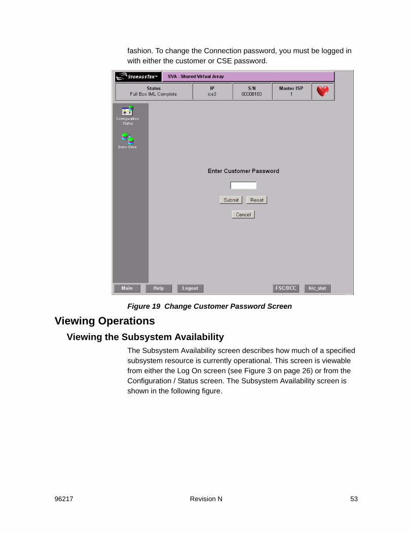
fashion. To change the Connection password, you must be logged in with either the customer or CSE password.
Figure 19 Change Customer Password Screen
Viewing OperationsViewing the Subsystem Availability
The Subsystem Availability screen describes how much of a specified subsystem resource is currently operational. This screen is viewable from either the Log On screen (see Figure 3 on page 26) or from the Configuration / Status screen. The Subsystem Availability screen is shown in the following figure.

54 Revision N 96217
Figure 20 Subsystem Availability Screen
Viewing the Status of the FRU ConfigurationThe FRU CONFIGURATION screen describes the configuration and status of the Field-Replaceable Units (FRUs) in the subsystem including their hardware and software serial numbers, Engineering Change (EC) levels, and compatibility levels.

96217 Revision N 55
This screen is accessed via the following menu path:
Figure 21 FRU Status Screen
Drain OperationsDrain operations, or removing customer data from an array or part of an array is done with the Drain Drive screen. The Drain Drive screen is a selection from the main menu after logging in with either the service representative or Customer password. A subsequent screen show the progress of any drain in progress (sometimes this can take a long period of time).On the Drain Drive Page, select:
- A whole drive tray by clicking the square in the tray area (the white area) for JBOD0 through JBOD3.
- Individual drives or more than one drive by clicking the square in each drive.
CSE/CustomerFRU StatusMain Menu

56 Revision N 96217
Note: You need to check the net capacity load (NCL) before beginning a drain operation. The upper limits are:
- 2 arrays < ~43% NCL- 3 arrays < ~57% NCL- 4 arrays < ~65% NCL
Figure 22 Drain Request Page Screen (upper part)
96217 Revision N 57
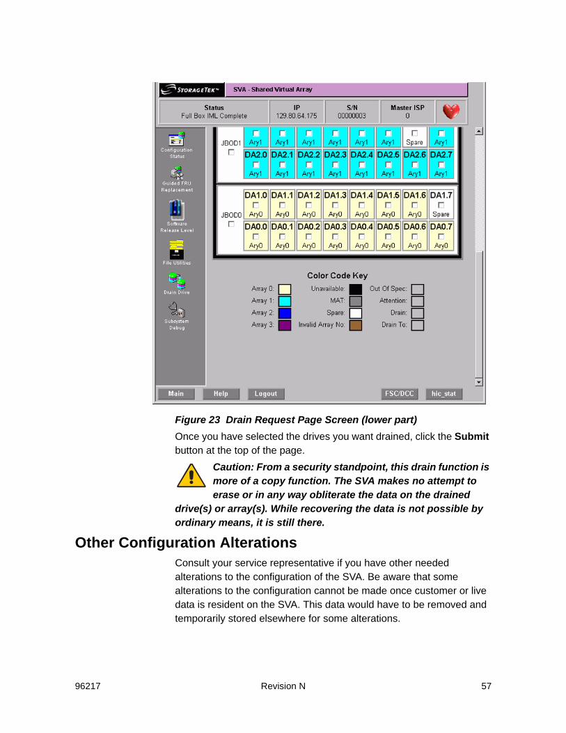
Figure 23 Drain Request Page Screen (lower part)Once you have selected the drives you want drained, click the Submit button at the top of the page.
Caution: From a security standpoint, this drain function is more of a copy function. The SVA makes no attempt to erase or in any way obliterate the data on the drained
drive(s) or array(s). While recovering the data is not possible by ordinary means, it is still there.
Other Configuration AlterationsConsult your service representative if you have other needed alterations to the configuration of the SVA. Be aware that some alterations to the configuration cannot be made once customer or live data is resident on the SVA. This data would have to be removed and temporarily stored elsewhere for some alterations.

58 Revision N 96217
96217 Revision N 59
4Error Recovery Actions
General Operator Error Recovery ActionsFor a fault or error that is not an array failure, the operator should perform the following procedure:
1. Generate an error report for the subsystem.
2. Record all of the information that is available about the fault or error including any information displayed on the . This includes:
- The site location number, subsystem model number, and serial number of the machine which are displayed on the SUBSYSTEM CONFIGURATION screen.
- The fault symptom code, which may be displayed on the , included in the SIM REFCODE or included in the error report.
- The REFCODE which is included in the SIM alert.- The FRUID which may be displayed on the or included in the
error report.
3. Perform a Fault Symptom Code (FSC) lookup. (Refer to “FSC/DCC Lookup”.)
4. Record the phone number of the phone nearest to the subsystem.
5. Call for service. (If the subsystem is supported by ServiceTek Plus, this step is automatically performed by the subsystem.)
FSC/DCC LookupAny time you find a Fault Symptom Code (FSC) or Diagnostic Condition Code (DCC) on the DOP, you may look up that code’s meaning by using the following procedure:
1. Click on the FSC/DCC button found in the lower right of most screens.
2. Clicking on that button brings up the lookup screen as shown in Figure 24 on page 60.
3. Click on either the “Lookup FSC Description” (default) radio button, or click in the “Lookup DCC Description” radio button.

60 Revision N 96217
4. Enter the FSC or DCC code in the window.
5. Click on the Submit button. The results of the search are shown in the something as shown in Figure 24.
Figure 24 FSC/DCC Lookup Screen with FSC3a41 Showing.Note: The results of a DCC lookup are similar.
6. You may look up another code or close that window when you are done.
Low Capacity FSC 3E41 MessagesWhen there is less than 10% collected free space, SVA reports this shortage by issuing a Service Information Message (SIM). The SIM contains a REFCODE, the first two bytes of which are the fault symptom code ’3E41’ that indicates low on capacity. The fault symptom code ’3E40’ indicates that the back-end capacity has been exhausted. At the same time, the V2X/V2X2 changes its thresholds to allow Free Space Collection (FSC) to do more work. This allows Free Space Collection routines to collect free space from more array cylinders so that new data can be written. As the V2X/V2X2 approaches 0% Collected Free Space (CFS), the Free Space

96217 Revision N 61
Collection routine is allowed access to more array cylinders as it tries to collect all free space remaining in the subsystem.If you receive this low-on-capacity SIM, take the following steps:
1. Monitor FSC using SVAA Space Utilization reports or SVAA and the V2X/V2X2 local operator panel.
2. Identify which files or functional device can be migrated to another storage subsystem or backed up to tape.
3. Initiate the migration of the files or functional device to another storage subsystem or back up the files or functional device to tape.
4. Delete the files or functional device. (To delete a functional device, first vary the functional device offline to all attached hosts.)
5. Wait for free space collection and DDSR to return the capacity to the available cylinders pool.
Note: When a file or a functional device is deleted, the disk array capacity that it occupied may not become available for several minutes to several hours.
If the V2X/V2X2 has no more array cylinders to allocate, it no longer accepts any commands that require a write operation including commands that are issued to browse, scratch, or delete a data set. Such commands are rejected with INTERVENTION REQUIRED sense data.If you receive an out-of-capacity SIM, take the following steps:First, check for uncollected free space. If there is uncollected free space, free space collection collects it and the Intervention Required state is reset. Reduce the update write and write/delete content of the user workload and then follow the low-on-capacity procedure. If no uncollected free space exists:
1. Migrate data to archives.
2. Delete volumes with temporary or old data currently not in use.
3. Add storage capacity to increase the collected free space to acceptable levels. Acceptable levels would be considered 15-20% collected free space.
Note: At this point, deleting files is not sufficient; you must delete a functional device.
4. Initiate the migration of the functional device to another storage subsystem or back up the functional device to tape.
5. Vary the functional device offline to all attached hosts.
62 Revision N 96217
6. Delete the functional device.
7. Wait for free space collection and DDSR to return the capacity to the available cylinders pool.
Note: When a functional device is deleted, the disk array capacity that it occupied may not become available for several minutes to several hours.
If the V2X/V2X2 has no more array cylinders to allocate, it no longer accepts any commands that require a write operation including commands that are issued in an attempt to browse, scratch, or delete a data set. Such commands are rejected with INTERVENTION REQUIRED sense data.The subsystem cancels the INTERVENTION REQUIRED condition when enough user capacity is available to sustain write activity.Another strategy for managing a subsystem’s CFS is to:• Designate one functional device in the Production partition as a
work volume.• This functional device should contain an expendable data set (e.g.,
a work volume of temporary data) that occupies at least 64 megabytes of capacity.
• Designate one functional device with low write activity as a privileged ECAM device.
• This is the ECAM device that accepts the write operation and allow you to delete the work volume.
PPRC Secondary Devices RecoveryIn the event that the primary SVA has become disabled, use the following procedure to recover PPRC secondary volumes so the host can access these volumes.

96217 Revision N 63
1. Use the following menu sequence to get to the Terminate PPRC screen.
Figure 25 Terminate PPRC Screen
2. At the Terminate PPRC screen, click on either the SSIDs desired or click on the ALL SSIDs button to terminate the PPRC secondaries.
Terminate PPRCCSE/Customer Login CSE/Customer Main Menu

64 Revision N 96217
3. The Terminate PPRC screen will show a warning as shown below. Click on the Continue to complete the termination.
Figure 26 PPRC Termination Warning (upper half)

96217 Revision N 65
Figure 27 PPRC Termination Warning (lower half)Note: All devices that were PPRC secondary devices will be put in the
simplex state.
The SVA will do a warm start at this time.

66 Revision N 96217
96217 Revision N 67
5Exception Conditions
FencingThe SVA has removed the responsibility for fence management from the operator by automatically isolating failed resources and clearing an imposed fence when the resource has been replaced. The service representative performs the only human intervention required in the fence-processing sequence. Therefore, the SVA Controller rejects the ICKDSF CONTROL CLEARFENCE command.An SVA does not fence functional devices, which are the equivalent of conventional devices behind a 3990. Since data is stored to, and accessed from, multiple physical drive modules within an array, there are multiple paths to a functional volume from the Controller. Should an error occur that restricts access to a physical device within the array, the drive reconstruction recreates the data stored on that device and places it on a spare drive.
Data Assurance Check ModeIn certain conditions, an SVA subsystem may enter a data assurance check mode. In this state, data cannot be assured to be correct and commands that access data are not accepted.The conditions that cause the subsystem to enter a data assurance check mode are:• The battery backup units that support NonVolatile Storage (NVS)
have discharged after a power failure with modified records in NVS• The mapping tables cannot be completely recovered during a
Controller initialization.In data assurance check mode, sense bytes 22 and 23, which contain the fault symptom code, are 9203 or E203. The console log for this time period may provide more information about the condition.You can reset this condition and exit from this state by resetting the data assurance check mode at the local operator panel. After resetting the subsystem, normal operation can proceed; however, you must take steps to determine what, if any, data has been compromised.

68 Revision N 96217
Pinned DataTraditionally, pinned data is data in cache that cannot be written to a device and, thus, must remain in cache until it is manually erased. Pinned data is usually the result of an un-correctable media failure where the record is stored.An SVA subsystem does not experience pinned data because of dynamic mapping. All write operations result in a functional track being copied from cache to a disk array. The functional track is always written to a new location, never to the position from which it was read.
Exception ReportingThe SVA exception conditions are reported in several ways and can be collected and formatted by using the following utilities.
EREP Exception ReportingThe use of Environmental Record Editing and Printing (EREP) for exception reporting is of minimal value with the SVA. Most problems are resolved within the subsystem and are not visible to the host. Correctable errors are resolved using the redundancy data to reconstruct damaged functional tracks.
Using SIMsService Information Messages (SIM) contain sense data that describe certain error conditions encountered by the subsystem. All SIMs are recorded in the Error Recording Data Set (ERDS). Based on the SIM sense data, a SIM alert is sent to the operator console indicating that an error condition has been encountered and recorded in the ERDS.A SIM alert includes:• Machine type and model• Plant of manufacture and machine serial number• Failing part of the subsystem• Severity of the failure• Effect of the repair• REFCODE.When requesting service, the customer reports the machine type and machine serial number.The SIM sense data recorded in the ERDS contains more specific information about the error than does the SIM alert message. The Environmental Record Editing and Printing (EREP) program or a
96217 Revision N 69
similar program can be used to produce a report describing the details of the error.SIM alerts are issued to the operator console based on the severity of the error. An SVA subsystem generates SIM alerts for the following types of error conditions:• Controller failures• Cache failures• Device failures.The SVA does not generate SIM alerts for media failures because the disk arrays allow the dynamic recovery of any data stored on failed media. For more information about track recovery and drive reconstruction, refer to the introduction and reference manuals for the V2X/V2X2.SIM sense data is also generated for conditions that are unique to the SVA. The unique conditions detected by the SVA are:• Low number of spare drives• Low NVS battery voltage• Physical device failure: reconstruction process initiated• Physical device failure: reconstruction process completed• Net Capacity Load (NCL) threshold exceeded• Drain operation complete• Battery back to full charge• Out of back-end space.A SIM alert for these unique conditions may be generated based on the severity of the condition. For information about SVA specific SIMs and SIM alerts, refer to the 9500 Shared Virtual Array Reference.
Establishing SIM Handling ProceduresIn an MVS environment, a SIM alert remains on the operator console until the operator or storage administrator responds to the message. When a SIM alert is detected, the “A3” records generated by the SIM should be collected from all attached systems’ ERDS. To do this, run EREP with the input ERDS merged.For MVS, the process to collect the “A3” records can be automated in several ways. The appropriate JCL and control statements necessary to generate an EREP report can be stored in a procedure library and invoked from a CLIST or REXX EXEC. Most console message automation utilities can be used to initiate an EREP report following a SIM alert.
70 Revision N 96217
Because SIM alerts in the VM environment do not require a response, the operator may miss the message. The operator can be made aware of SIM occurrences by the A3 records from the ERDS must be collected from all attached subsystems.For further information on EREP or IBM 3990 disk controllers, refer to the IBM Publications KWIC Index for the appropriate manual.If a subsystem is supported by ServiceTek Plus, the subsystem produces two types of ServiceTek Plus alerts that initiate automatic connection to the Customer Service Center (CSC).
Unit Failure – This type of alert occurs when there has been an SVA subsystem failure, when an SVA subsystem is about to fail, or when the SVA subsystem is running with degraded performance.Trace/Event Log Down-Load – This type of alert occurs periodically and involves the down-loading of diagnostic data. Additionally, when the SVA subsystem performance and statistical thresholds have been reached, a call is initiated to CSC, and subsystem data is down-loaded.
The ServiceTek Plus Facility can be enabled or disabled through the LOP or via a CSC login. If ServiceTek Plus is disabled, a record is entered in the file HIC_STAT.dia indicating that ServiceTek Plus is disabled. In this event, exception conditions are still logged and are accessible through the LOP or a CSC login.
Disk Array RecoveryThe SVA Control Unit can automatically recover from a simultaneous failure of two drive modules in the same array. Redundancy data is read from the remaining drives in the array and the data is reconstructed on a spare drive. However, three simultaneous device failures within a single array is considered an array failure because insufficient redundancy data remains to reconstruct the failing devices.
Recovery ProcedureThe following procedure provides a guideline for recovering data from an SVA subsystem in the event of an array failure. Tailor this procedure to your environment. Upon discovering an array failure:
1. Immediately halt all update activity to the subsystem.
2. Initiate DDSR processing for all functional volumes in the subsystem. This deletes un-allocated data space within the subsystem.

96217 Revision N 71
3. Begin a functional volume dump operation for all of the volumes on the subsystem. This step captures the remaining data specifying DATA ONLY for the dump operation. Use the CYLINDER processing option for the target devices to maximize performance.
4. Using the reports generated in the dump process, identify the data sets that could not be dumped because of I/O errors.
5. Un-catalog and delete the unreadable data sets.
6. Recover and/or restore the data sets identified as unreadable from the most current backup available.
7. Perform forward recovery for restored data sets, as needed.
8. Resume normal processing.
The time required to perform the entire procedure depends upon the Net Capacity Load and the size of the subsystem. However, use the following formulas to estimate the “expected” time required to perform the dump operation. (The two examples provided here are extreme cases, but they may be used to estimate the time for a specific site.)
Recovery Time EstimateThe amount of data contained on an SVA subsystem (its functional load) can be determined by multiplying the physical capacity by the Net Capacity Load and dividing that value by the compression-compaction index:
(physical capacity) X (% Net Capacity Load) functional load = -------------------------------------------------------------- (compression-compaction index)Using the functional load, the amount of time required to dump that data can be estimated by multiplying the channel speed by the number of channels and dividing that value into the functional load. However, this formula assumes that tape devices are not a constraining factor. (functional load) dump time (sec) = ----------------------------------------------------- (channel speed X number of channels)As indicated, the result is in the number of seconds required. The number of minutes required may be obtained by dividing that value by 60.

72 Revision N 96217

96217 Revision N 73
ADrive Module Status
The following table lists and describes the status designations for a drive module. The drive module status is represented by a two-character code: the first character identifies the partition with which the drive is associated; the second character displays the current state of the drive.Status codes are displayed either as two characters or as two characters separated by a period. For example, the status of a drive module associated with the Production Partition in the active state is “PA” or “P.A.”.
Table 2 Drive Module Status Descriptions
Partition State MeaningProduction PartitionProduction: Active P.A. (PA) Drive module is a member of an array that is
associated with the Production partition.Production: Broken P.B. (PB) Drive module has been marked as broken. It
remains in this state until reconstruction is complete. It also appears as U.B. in the unavailable partition.
Production: Copy (receiving drain data)
P.C. (PC) Drive module is receiving data from the drain of a single drive module in the Production partition.
Production: Draining P.D. (PD) Drive module is being drained.Production: Initialize array P.I. (PI) Drive module is part of an array initialization
process.Production: Pending drain P.P. (PP) Drive module is waiting to be drained. The drain
cannot begin for one of the following reasons:A drive module reconstruction is in progress.Another drive in the array is being drained.The number of available spares is inadequate (this can occur if the number of spares was reduced after the drain request was accepted).

74 Revision N 96217
Production: Reconstruction
P.R. (PR) Drive module is being used to reconstruct data for a Production partition drive module that failed.
MAT PartitionMAT: Active M.A. (MA) Drive module is a member of an array that is
associated with the MAT partition.MAT: Broken M.B. (MB) Drive module has been marked as broken. It
remains in this state until reconstruction is complete. It appears as U.B. in the unavailable partition.
MAT: Copy (receiving drain data)
M.C. (MC) Drive module is receiving dat5a from the drain of a single drive module in the MAT partition.
MAT: Draining M.D. (MD) Drive module is being drained.MAT: Initialize array M.I. (MI) Drive module is part of an array initialization
process.MAT: Pending drain M.P. (MP) Drive module is waiting to be drained. The drain
cannot begin for one of the following reasons:A drive module reconstruction is in progressAnother drive in the array is being drainedThe number of available spares is inadequate (this can occur if the number of spares was reduced after the drain request was accepted).
MAT: Reconstruction M.R. (MR) Drive module is being used to reconstruct data for a MAT partition drive module that failed
Spares PartitionSpare: Active S.A. (SA) Drive module is available for forming arrays, for
data reconstruction, or for receiving data from a drain of a single drive module
Spare: Fenced S.F. (SF) Drive module is fenced for a periodic drive testSpare: Pending drain S.P. (SP) Drive module is waiting to be drained pending
completion of a periodic drive testUnavailable PartitionUnavailable: Broken U.B. (UB) Drive module in slot is brokenUnavailable: Isolated U.I. (UI) Unavailable and isolatedUnavailable: No active drive module
U.N. (UN) No active drive module is sensed in slot, or slot has not been installed
Table 2 Drive Module Status Descriptions (Continued)
Partition State Meaning

96217 Revision N 75
BService Information Messages
SIM OverviewThe SVA support processor constantly monitors the SVA operations for “change-in-status” conditions. When it detects such a condition and determines that the condition should be reported to the host, the ISP generates a Service Information Message (SIM). It then sends the SIM to a host console on the subsequent I/O operation asynchronous of the change-in-status condition. If the subsystem is ServiceTek Plus-equipped, a Machine Initiated Maintenance (MIM) event may also be sent to the Customer Service Center (CSC). The SVA generates service SIMs based on the change-in-status condition detected. Because of its RAID architecture, unlike the 3390 and 3990, the SVA does not generate media SIMs. Media maintenance is internal to the Disk Array Units; it does not require Controller or host ERPs or operator intervention.A service SIM is a text message that notifies users and service personnel that the subsystem hardware has experienced a condition requiring a service action, that subsystem operation may be affected by a threshold being reached or other event, or that general service-related information is being conveyed to the user. A service SlM acts as the service-action trigger for an SVA subsystem. The subsystem sends a service SIM when the ISP has detected an error condition, threshold, or event, AND has:• Fenced and/or isolated the Field-Replaceable Unit (FRU) that
requires serviceOR
• Determined that the error cannot be isolated or corrected by the SVA’s extensive internal error recovery programs or user intervention may be required.
In most cases, the SVA Control Unit executes error recovery actions. Host ERP involvement is delayed until after the failing FRU has been isolated. This frees up host resources for other processes. However, in certain conditions, full host ERP involvement is required.
76 Revision N 96217
A service SIM identifies the error condition and its severity classification, the general hardware area that experienced the fault, the impact of the failure, the FRU requiring service, and the impact of the repair.The service SIM reduces the amount of work an operator or service representative must do to identify and isolate a problem and to request service.In general, if a service SIM is reported and the required repair is not made, the SIM is reported two more times at approximately eight hour intervals. If the subsystem is powered down before the SlM count of three is reached, the SIM reporting process continues after the next power-on IML is completed.SIMs are not issued during IML or until 16K start I/O operations have occurred. All SIMs, both initial reporting or repeat events, are stored on the subsystem until these conditions have been met.SIMs that have a severity of SERVICE are information SIMs and generally do not require a service call. They provide information about the status of specific situations such as a remote session or drain operation. Usually, SIMs at a severity level of service are reported only once.If a SIM cannot be issued to the host due to channel unavailability, no further SIMs are issued until that initial failing SIM can be sent to and acknowledged by the host. The ISP periodically checks for acknowledgement and re-send the SIM until this occurs. In the meantime, all subsequent SIMs accumulate in the SIM database on the ISP and are eventually sent to the host. No SIMs are discarded until all initial and repeat occurrences have been sent to and acknowledged by the host.
SIM Alert Message FormatsAs stated previously, the SVA notifies the operator that a SIM event has occurred via a SlM alert message at the host operator console. While the SVA may create unique SIMs (SIMs different than those produced by the 3990-3), the SIM alert messages sent to the operator console are, in general, consistent with those sent by the 3990-3. In only a few instances are the SIM alert messages unique to the SVA.Figure 28 represents the general format of a SIM alert message. Figure 29 and Figure 30 are examples of a SlM alert message for the
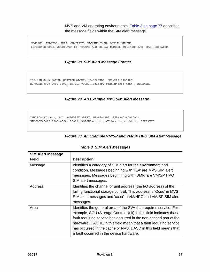
96217 Revision N 77
MVS and VM operating environments. Table 3 on page 77 describes the message fields within the SIM alert message.
Figure 28 SIM Alert Message Format
Figure 29 An Example MVS SIM Alert Message
Figure 30 An Example VM/SP and VM/SP HPO SIM Alert Message
Table 3 SIM Alert Messages
SIM Alert Message Field DescriptionMessage Identifies a category of SIM alert for the environment and
condition. Messages beginning with ‘IEA’ are MVS SIM alert messages. Messages beginning with ‘DMK’ are VM/SP HPO SIM alert messages.
Address Identifies the channel or unit address (the I/O address) of the failing functional storage control. This address is ‘Ocuu’ in MVS SIM alert messages and ‘ccuu’ in VM/HPO and VM/SP SIM alert messages.
Area Identifies the general area of the SVA that requires service. For example, SCU (Storage Control Unit) in this field indicates that a fault requiring service has occurred in the non-cached part of the hardware. CACHE in this field mean that a fault requiring service has occurred in the cache or NVS. DASD in this field means that a fault occurred in the device hardware.
MESSAGE, ADDRESS, AREA, SEVERITY, MACHINE TYPE, SERIAL NUMBER
REFERENCE CODE, SUBSYSTEM ID, VOLUME AND SERIAL NUMBER, CYLINDER AND HEAD, REPEATED
IEA480E Ocuu,CACHE, SERVICE ALERT, MT=9200XD3, SER=200-00000001
REFCODE=0000-0000-0000, ID=01, VOLSER=volser, cchh=x’cccc hhhh’, REPEATED
DMKDAD403I ccuu, SCU, MODERATE ALERT, MT=9200XD3, SER=200-00000001
REFCODE=0000-0000-0000, ID=01, VOLSER=volser, CChh=x’ cccc hhhh’ , REPEATED
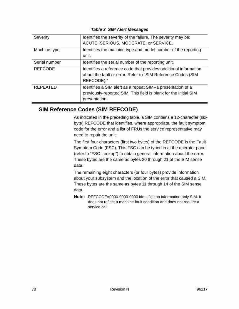
78 Revision N 96217
SIM Reference Codes (SIM REFCODE)As indicated in the preceding table, a SIM contains a 12-character (six-byte) REFCODE that identifies, where appropriate, the fault symptom code for the error and a list of FRUs the service representative may need to repair the unit.The first four characters (first two bytes) of the REFCODE is the Fault Symptom Code (FSC). This FSC can be typed in at the operator panel (refer to “FSC Lookup”) to obtain general information about the error. These bytes are the same as bytes 20 through 21 of the SIM sense data.The remaining eight characters (or four bytes) provide information about your subsystem and the location of the error that caused a SIM. These bytes are the same as bytes 11 through 14 of the SIM sense data.Note: REFCODE=0000-0000-0000 identifies an information-only SIM. It
does not reflect a machine fault condition and does not require a service call.
Severity Identifies the severity of the failure. The severity may be: ACUTE, SERIOUS, MODERATE, or SERVICE.
Machine type Identifies the machine type and model number of the reporting unit.
Serial number Identifies the serial number of the reporting unit.REFCODE Identifies a reference code that provides additional information
about the fault or error. Refer to “SIM Reference Codes (SIM REFCODE).”
REPEATED Identifies a SIM alert as a repeat SIM--a presentation of a previously-reported SIM. This field is blank for the initial SIM presentation.
Table 3 SIM Alert Messages

96217 Revision N 79
SIM ALERT Severity LevelsTable 4 lists the different severity levels established for SIM alert messages. It also describes the general effect on the system and applications of the condition that caused the SIM alert.
Table 4 SIM Severity Levels
Severity Field Meaning Recommended ActionSERVICE No system or application
performance degradation is expected in any environment. No system or application outage has occurred. The SIM is presented purely for informational purposes.
Although presented for informational purposes, the SIM may be part of a larger impact on system operations. Therefore, if accompanied by other higher-severity SIMs, an evaluation of the potential effects on system operations in terms of the higher severity SIMs is warranted.Otherwise, no specific action need be taken unless directed by local site data collection procedures.
MODERATE
Performance degradation is possible in a heavily loaded environment. No system or application outage has occurred.
Promptly evaluate the effects on system operations. As required, plan for service action by the customer service engineer.If you defer action, application outages and/or unacceptable performance degradation may occur if previously recoverable exceptions become unrecoverable.
SERIOUS A primary I/O resource in the subsystem is disabled. Significant performance degradation is possible. System or application outage may have occurred.
Immediately evaluate the effect on system operations. Plan appropriate system recovery actions.Call for service action which is required to restore the unit to full operation.

80 Revision N 96217
SIM Logging and ReportingAt the host, a host Error Recovery Procedure (ERP) logs the SIM in the Error Recording Data Set (ERDS). If the SIM severity level is less than or equal to a pre-established severity level threshold (refer to “SIM Severity Reporting Option”), a SIM alert message is sent to the operator console. The SIM alert message contains a subset of the information included in a SIM. Refer to “SIM Alert Message Formats” for more information about the SIM alert message.Because the ERDS often contains more detailed information about the condition than the SIM alert message, the host Environmental Record Editing and Printing (EREP) program, or a similar program, can be used to produce a report describing the error.Error reports such as these speed problem determination and can help you to decide when to request immediate or deferred service.
SIM Severity Reporting OptionThe SVA allows you to select which SIM alert messages are sent to the host console although the selection must be implemented by a service representative.The following SIM severity reporting options are available:
ACUTE A major I/O resource in the subsystem is disabled, or damage to the unit is possible. Performance may be severely degraded. System and/or application outages may have occurred.
Treat as an emergency. Evaluate the current or potential effect on system and application operations. Determine appropriate system recovery actions or actions to prevent possible product damage.Call for service action which is required to restore the unit to full operation.
Setting Reporting OptionZero All SIMs are reported as SIM alert messages.One All SIMs, except those with the lowest severity, SERVICE, are
reported as SIM alert messages. Two Only SIMs with the two highest severity levels, SERIOUS and
ACUTE, are reported as SIM alert messages.Three Only SIMs with the highest severity level, ACUTE, are reported
as SIM alert messages.
Table 4 SIM Severity Levels (Continued)
Severity Field Meaning Recommended Action

96217 Revision N 81
Note: ACUTE alerts cannot be suppressed.
As shipped, the severity reporting option is pre-set to zero; therefore, all SIMs are reported as SIM alert messages. Upon installation, you may request that the service representative change the severity reporting option. However, if you modify the setting, we recommend that:• You do not suppress alerts with a severity higher than
MODERATE.• You regularly run EREP to extract the System Exception Report
which contains detailed SIM activity for ALL logged SIM activity including those that have had SIM alert console messages suppressed.
To have SIMs automatically initiate EREP, keep the SIM severity reporting option at three. In this case, when a SIM alert message is received and the full SIM is logged in the error recording log, it is automatically included in an Asynchronous Notification Record Detail report.
Machine-Initiated Maintenance (MIM)Machine-initiated maintenance reduces on-site service representative requirements by automatically reporting whether a system is inoperable, degraded, subject to potential failure, or ready to off-load event log data. When a fault condition occurs or a download timer expires, a MIM alert message is sent to a remote service center PC.Messages concerning actual or potential unit problems are sent as they occur; critical messages are repeated at 24-hour intervals until servicing is complete. The remote support center (Customer Service Center or CSC) evaluates the messages to determine maintenance requirements, then performs remote servicing or dispatches a service representative for service.
SVA Generated SIMs and MIMsTable 5 on page 82 provides a partial list of the SIM and MIM events generated by the SVA, listed by functional area and fault symptom code, problem description, severity, and whether a MIM event is also issued.PSA-generated SIMs are not listed because a specific problem may be manifested by several Fault Symptom Codes occurring at different times or frequencies. All PSA-originated SIM/MIM events range in severity from MODERATE to ACUTE. They may contain SIMs, MIMs, or both depending on the precise nature of the problem isolated and

82 Revision N 96217
being reported by PSA. In all cases, the action to be taken by the user is to examine the subsystem operator panel menu giving further information on the CFE_ID being reported. A PSA-originated SIM/MIM event is identified by byte 29 and byte 30 bits 0-3 containing a value between 0x64 and 0x1000 (100-4096) which is the CFE_ID.
Table 5 System-Generated SIM and MIM Events
Functional Area/FSC Problem Description Severity
MIMIssued
Extended Control and Monitoring (ECAM) events
730C HOST INITIATED MAT COMPLETE SERVICE No
730D HOST INITIATED DRAIN COMPLETE SERVICE No
7328 OP PANEL INITIATED DRAIN COMPLETE SERVICE No
7329 OP PANEL INITIATED MAT COMPLETE SERVICE No
Low Spares events
3E5F NEED SPARES!!! ACUTE Yes
3E61 ONE SPARE REMAINING SERIOUS Yes
3E62-5 2-5 SPARES REMAINING MODERATE Yes
3E66-F 6-15 (OR MORE) SPARES REMAINING SERVICE Yes
Drive Reconstruction events
3E01 DRIVE RECONSTRUCTION BEGIN SERVICE No
3E02 DRIVE RECONSTRUCTION END SERVICE No
Conditional Capacity (none remaining or threshold reached) eventsa
3E40 PRODUCTION PARTITION-NONE REMAINING
ACUTE No
3E41 PRODUCTION PARTITION-THRESHOLD REACHED
SERIOUS No
Subsystem Security (Secure Options) events
71C2 through 71C9
SECURITY VIOLATION MODERATE Yes
7201 SECURITY VIOLATION UNCORRECTED MODERATE Yes
7200 SECURITY VIOLATION ONGOING MODERATE Yes
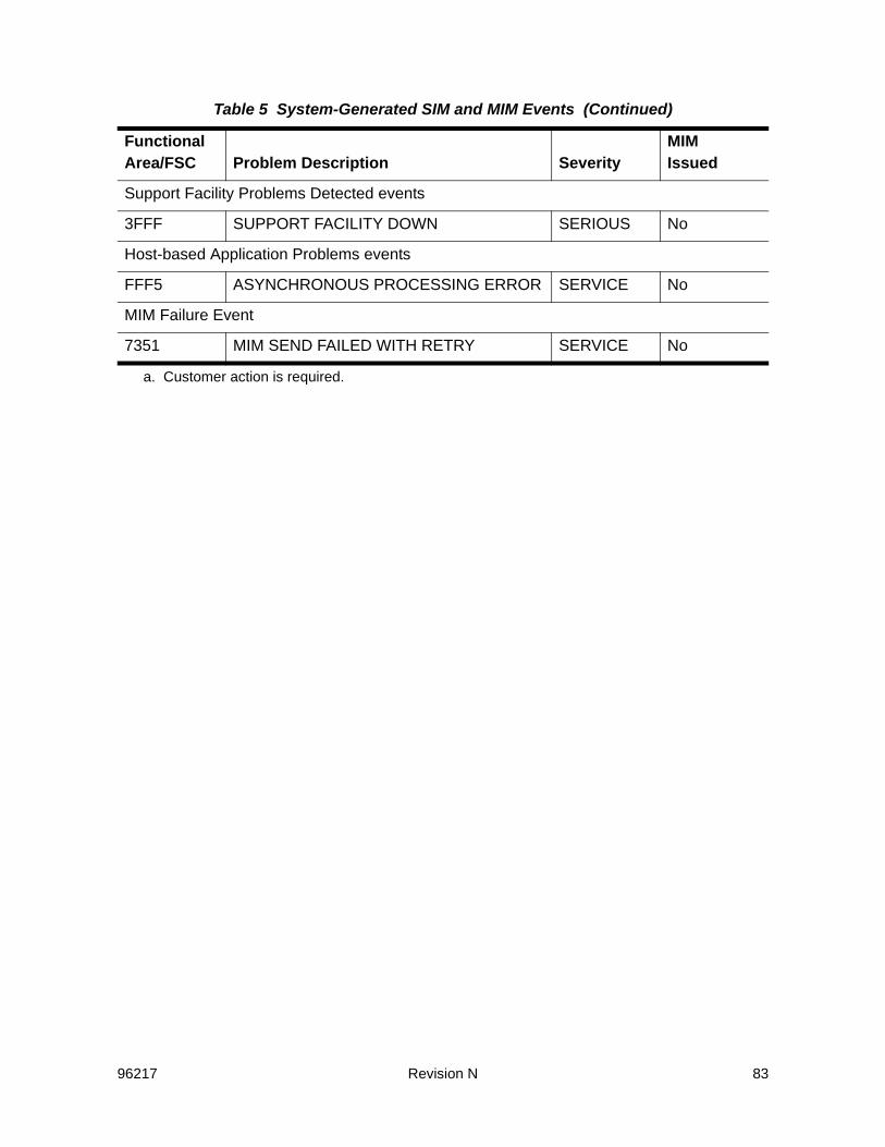
96217 Revision N 83
Support Facility Problems Detected events
3FFF SUPPORT FACILITY DOWN SERIOUS No
Host-based Application Problems events
FFF5 ASYNCHRONOUS PROCESSING ERROR SERVICE No
MIM Failure Event
7351 MIM SEND FAILED WITH RETRY SERVICE No
a. Customer action is required.
Table 5 System-Generated SIM and MIM Events (Continued)
Functional Area/FSC Problem Description Severity
MIMIssued

84 Revision N 96217
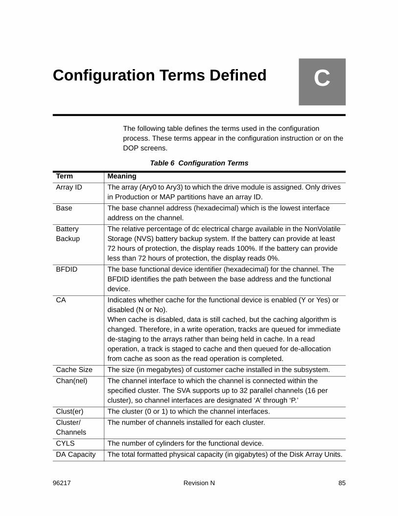
96217 Revision N 85
CConfiguration Terms Defined
The following table defines the terms used in the configuration process. These terms appear in the configuration instruction or on the DOP screens.
Table 6 Configuration Terms
Term MeaningArray ID The array (Ary0 to Ary3) to which the drive module is assigned. Only drives
in Production or MAP partitions have an array ID.Base The base channel address (hexadecimal) which is the lowest interface
address on the channel.Battery Backup
The relative percentage of dc electrical charge available in the NonVolatile Storage (NVS) battery backup system. If the battery can provide at least 72 hours of protection, the display reads 100%. If the battery can provide less than 72 hours of protection, the display reads 0%.
BFDID The base functional device identifier (hexadecimal) for the channel. The BFDID identifies the path between the base address and the functional device.
CA Indicates whether cache for the functional device is enabled (Y or Yes) or disabled (N or No).When cache is disabled, data is still cached, but the caching algorithm is changed. Therefore, in a write operation, tracks are queued for immediate de-staging to the arrays rather than being held in cache. In a read operation, a track is staged to cache and then queued for de-allocation from cache as soon as the read operation is completed.
Cache Size The size (in megabytes) of customer cache installed in the subsystem.Chan(nel) The channel interface to which the channel is connected within the
specified cluster. The SVA supports up to 32 parallel channels (16 per cluster), so channel interfaces are designated ‘A’ through ‘P.’
Clust(er) The cluster (0 or 1) to which the channel interfaces. Cluster/Channels
The number of channels installed for each cluster.
CYLS The number of cylinders for the functional device.DA Capacity The total formatted physical capacity (in gigabytes) of the Disk Array Units.

86 Revision N 96217
Data Transfer The number of data transfer paths that are operational (maximum of four for 4 Data Path or eight for 8 Data Path).
Data Transfer Paths 0, 1, 2, and 3, or 0-8 for 8 Data Path feature
The percentage of data path resources that are operational.
Date and Time
Displays the current date and time, based on a 24-hour clock and displayed in Coordinated Universal Time (CUT).
Disk Array Controller
The number of operational dc power supplies available to support the Disk Array Controller (maximum of 4).
Disk Controller
The number of operational blower assemblies in the Disk Array Controller (maximum of 4).
Disk Drive Tray
The number of operational dc power supplies available to support the disk drive trays (maximum of 32).
Disk Drives The number of physical disk drives that are operational (maximum of 64).Drive Status The status of the drive module. The first character indicates the partition;
the second character indicates status (e.g., A = Active).Drive modules may be associated with one of four partitions, and they may have different status within the partition.
EC/N The engineering change level of the FRU.ENA(ble) Identifies whether host access to the functional device is enabled (Y or
Yes) or disabled (N or No).Enab(le) Identifies whether the channel interface is enabled (Y or Yes) or disabled
(N or No).FDID The hexadecimal identifier of the functional device. The FDID is a value
between 00 and 3FF.FEN-Type Indicates whether an FRU is fenced (Y or Yes), not fenced (N or No), or
partially fenced (P or Partially), and the type of fence imposed. When the subsystem fences an FRU, it is taken out of use until it can be replaced or repaired. Fencing does not disrupt the subsystem’s operation.A partially-fenced FRU indicates that some subset of the FRU (such as a port) is fenced, but all other portions of the FRU is unfenced.
FW Indicates whether DASD fast write for the functional device is enabled (Y or Yes) or disabled (N or No). All writes to the SVA are DASD fast writes; DASD fast write is never truly disabled.
Table 6 Configuration Terms (Continued)
Term Meaning
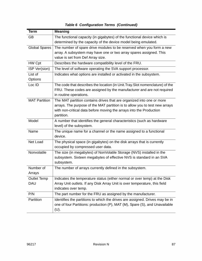
96217 Revision N 87
GB The functional capacity (in gigabytes) of the functional device which is determined by the capacity of the device model being emulated.
Global Spares The number of spare drive modules to be reserved when you form a new array. A subsystem may have one or two array spares assigned. This value is set from Def Array size.
HW Cpt Describes the hardware compatibility level of the FRU.ISP Ver(sion) The level of software operating the SVA support processor.List of Options
Indicates what options are installed or activated in the subsystem.
Loc ID The code that describes the location (in Unit.Tray.Slot nomenclature) of the FRU. These codes are assigned by the manufacturer and are not required in routine operations.
MAT Partition The MAT partition contains drives that are organized into one or more arrays. The purpose of the MAT partition is to allow you to test new arrays with non-critical data before moving the arrays into the Production partition.
Model A number that identifies the general characteristics (such as hardware level) of the subsystem.
Name The unique name for a channel or the name assigned to a functional device.
Net Load The physical space (in gigabytes) on the disk arrays that is currently occupied by compressed user data.
Nonvolatile The size (in megabytes) of NonVolatile Storage (NVS) installed in the subsystem. Sixteen megabytes of effective NVS is standard in an SVA subsystem.
Number of Arrays
The number of arrays currently defined in the subsystem.
Outlet Temp DAU
Indicates the temperature status (either normal or over temp) at the Disk Array Unit outlets. If any Disk Array Unit is over temperature, this field indicates over temp.
P/N The part number for the FRU as assigned by the manufacturer.Partition Identifies the partitions to which the drives are assigned. Drives may be in
one of four Partitions: production (P), MAT (M), Spare (S), and Unavailable (U).
Table 6 Configuration Terms (Continued)
Term Meaning

88 Revision N 96217
PRIV Indicates whether the functional device is a privileged ECAM device (Y or Yes) or not (No or No).To implement the SVAA software, you must designate at least one functional device as a privileged ECAM device--that is, as an eligible designation for Category 1-restricted messages. However, you should limit the number of such devices.
Production Partition
The Production partition contains drives that are organized into one or more arrays. Drives in the Production partition are used for storing and retrieving data.
PT The partition with which the functional device is associated. Functional devices must be in either the MAT partition or the Production partition.
Range The number of addresses (decimal) with which the channel can interface.Release Level
The level of software operating in the SVA Controller.
S/N (Serial Number)
The unique hardware number that identifies a specific subsystem.
Site Location Number
The number assigned by Sun Microsystems that identifies your site.
Site Name The unique name for your site. This name must be the same for all the SVA subsystems at a site.
Size Identifies the size and configuration of the array.In an SVA, 15 (13 + 2) physical devices are organized into a logical group. Within the group, user data is recorded on identically addressed tracks on all but two of the devices. The identically addressed tracks on the other two devices are reserved for the two levels of redundancy data generated by the subsystem.
Spares Partition
The Spares partition contains drives that are available for forming arrays. When you form a production array, the drives for the array are taken from the Spares partition. Also, when the subsystem reconstructs a drive, it reconstructs the data onto a drive from the Spares partition.
Speed The data transfer rate (in megabytes per second) of the channel. This value cannot be changed.
SSID The SubSystem IDentifier (SSID) for the functional storage control with which the functional device is associated.
Subsystem Name
The name of a specific subsystem at a site. Each subsystem should have a unique name.
Table 6 Configuration Terms (Continued)
Term Meaning

96217 Revision N 89
Support Facility
The number of operational dc power supplies available to support the system support processors (maximum of 2).
Total Cache The percentage of total cache that is operational. Total cache is the sum of user cache and the SVA’s reserved cache.
Type The type of channel interface installed. The SVA supports Fibre and ESCON channels. ORThe type of device that the functional device emulates. Functional devices may emulate 3380J, 3380K, 3380KE, 33901, 33902, 33903, or 33909 devices.
U.T.S. The SVA Unit (0), Tray (0 to 7), and Slot (0 to 7) in which the drive module is located.Note: “Slot” is referred to as “Drive Number” on the CD29 screen.Note: Some units may be only half-populated. Therefore, not all U.T.S. locations contain drive modules.
Unavailable Partition
The Unavailable partition includes any drive or drive slot (the physical space where a drive can be installed) that is not active. Thus, broken drives or empty drive slots are listed in the Unavailable partition.
User Cache The percentage of cache that is available for user data.WP Identifies whether the functional device is write protected (Y or Yes) or not
write protected (N or No). If the functional device is write protected, the data on it is read-only and cannot be overwritten.
Table 6 Configuration Terms (Continued)
Term Meaning

90 Revision N 96217
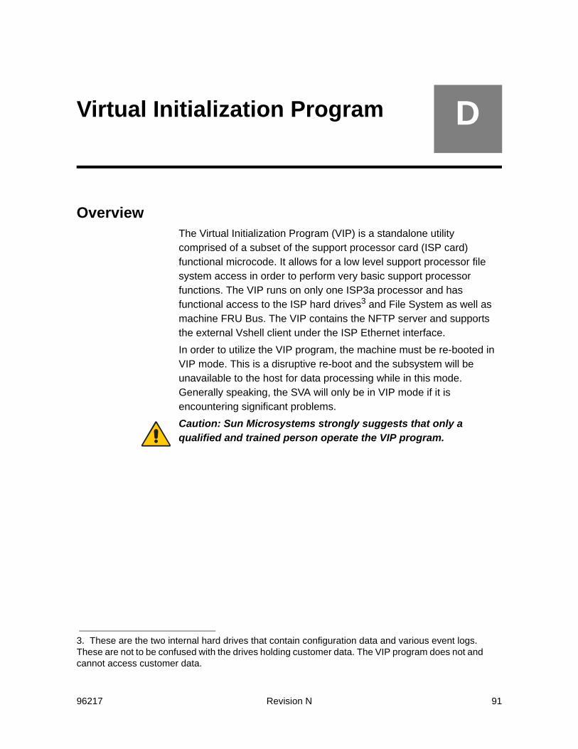
96217 Revision N 91
DVirtual Initialization Program
OverviewThe Virtual Initialization Program (VIP) is a standalone utility comprised of a subset of the support processor card (ISP card) functional microcode. It allows for a low level support processor file system access in order to perform very basic support processor functions. The VIP runs on only one ISP3a processor and has functional access to the ISP hard drives3 and File System as well as machine FRU Bus. The VIP contains the NFTP server and supports the external Vshell client under the ISP Ethernet interface.In order to utilize the VIP program, the machine must be re-booted in VIP mode. This is a disruptive re-boot and the subsystem will be unavailable to the host for data processing while in this mode. Generally speaking, the SVA will only be in VIP mode if it is encountering significant problems.Caution: Sun Microsystems strongly suggests that only a qualified and trained person operate the VIP program.
3. These are the two internal hard drives that contain configuration data and various event logs. These are not to be confused with the drives holding customer data. The VIP program does not and cannot access customer data.
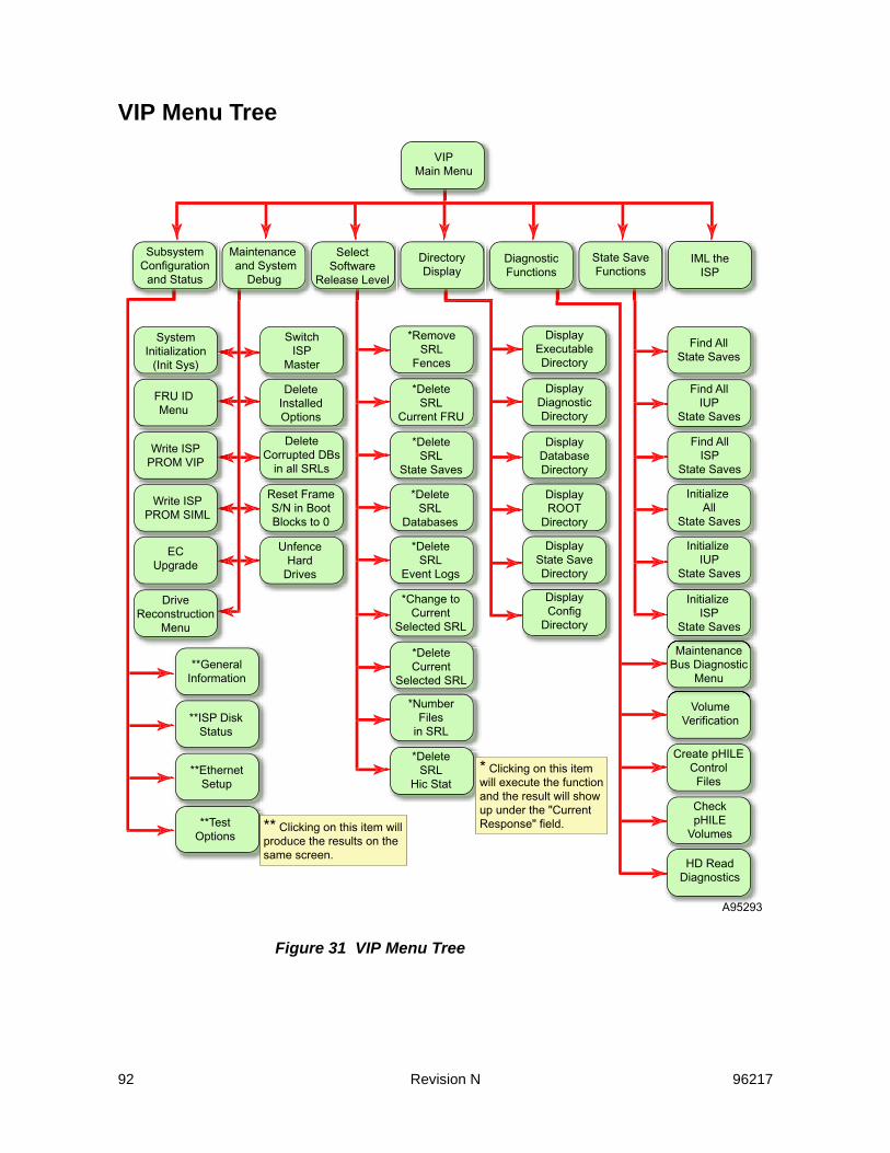
92 Revision N 96217
VIP Menu Tree
Figure 31 VIP Menu Tree
VIPMain Menu
SubsystemConfiguration
and Status
Maintenanceand System
Debug
SelectSoftware
Release Level
DirectoryDisplay
DiagnosticFunctions
State SaveFunctions
IML theISP
SystemInitialization
(Init Sys)
FRU IDMenu
Write ISPPROM VIP
Write ISPPROM SIML
ECUpgrade
DriveReconstruction
Menu
SwitchISP
Master
DeleteInstalledOptions
DeleteCorrupted DBs
in all SRLs
Reset FrameS/N in BootBlocks to 0
UnfenceHard
Drives
*RemoveSRL
Fences
*DeleteSRL
Event Logs
*DeleteSRL
Databases
*DeleteSRL
State Saves
*DeleteSRL
Current FRU
*Change toCurrent
Selected SRL
*DeleteCurrent
Selected SRL
*NumberFiles
in SRL
*DeleteSRL
Hic Stat
A95293
VolumeVerification
MaintenanceBus Diagnostic
Menu
Create pHILEControl
Files
CheckpHILE
Volumes
HD ReadDiagnostics
DisplayConfig
Directory
DisplayState SaveDirectory
DisplayROOT
Directory
DisplayDatabaseDirectory
DisplayDiagnosticDirectory
DisplayExecutableDirectory
* Clicking on this itemwill execute the functionand the result will showup under the "CurrentResponse" field.** Clicking on this item will
produce the results on thesame screen.
**GeneralInformation
**ISP DiskStatus
**EthernetSetup
**TestOptions
Find AllState Saves
Find AllIUP
State Saves
Find AllISP
State Saves
InitializeAll
State Saves
InitializeIUP
State Saves
InitializeISP
State Saves

96217 Revision N 93
VIP ScreensOn-Screen Functions and Indicators
On all VIP screens, the following buttons and indicators have these meanings:
HeartbeatThe heartbeat in the upper right corner of the VIP screens indicates various things by is graphic:• The red pulsating heartbeat indicates that the DOP is connected
and it is ready.• The red heart with the hourglass next to it indicates that there is a
program execution in progress.• The red heart with the circle and diagonal line through it indicates
that the connection to the SVA has been lost (even if only temporally as in when doing a re-boot).
• A disk drive replacing the heart with a percentage next to it indicates a drive rebuild is in progress and the percentage it has completed.
MainClicking on the button labeled Main will take you to the main menu. (See “VIP Menu Tree” on page 92.)
HelpClicking on the button labeled Help will bring up the help file and take you to the information relevant to the screen on which you clicked on the Help button. The help information for the Virtual Initialization Program is one long file.
hic stat4
Clicking on the button labeled Hic Stat will take you to the current Hic Stat file. The actual file name is hic.stat.dia.
FSC/DCCClicking on the button labeled FSC/DCC will bring up the look-up screen for both a Fault Symptom Code (FSC) or a Diagnostic Condition Code.
4. Hic stat stands for HumanInterfaceControl_STATus log.
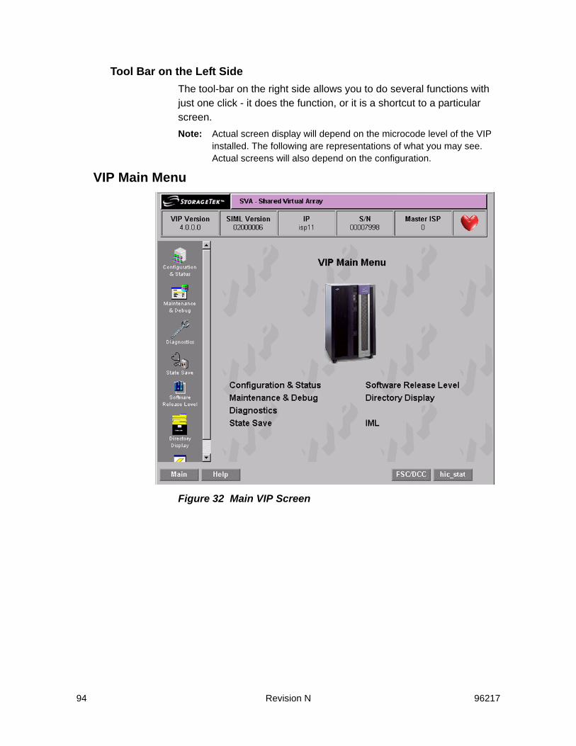
94 Revision N 96217
Tool Bar on the Left SideThe tool-bar on the right side allows you to do several functions with just one click - it does the function, or it is a shortcut to a particular screen. Note: Actual screen display will depend on the microcode level of the VIP
installed. The following are representations of what you may see. Actual screens will also depend on the configuration.
VIP Main Menu
Figure 32 Main VIP Screen

96217 Revision N 95
System Configuration and Status
Figure 33 VIP System Configuration and Status Screen

96 Revision N 96217
Maintenance and System Debug
Figure 34 VIP Maintenance and System Debug Screen

96217 Revision N 97
System Initialization
Figure 35 System Initialization ScreenAfter clicking on the “Initialize System” button, following screen will appear.

98 Revision N 96217
Figure 36 System Initialization Complete ScreenWhen this screen appears, verify that the IP address is correct. In the unlikely event that it is missing or incorrect, go to the “System Configuration and Status” on page 95 and enter the correct one.

96217 Revision N 99
FRU ID Menu
Figure 37 FRU ID Menu Screen

100 Revision N 96217
Write ISP PROM VIP
Figure 38 Write ISP PROM VIP Screen

96217 Revision N 101
Write ISP PROM SIML
Figure 39 Write ISP PROM SIML Screen

102 Revision N 96217
EC Upgrade
Figure 40 EC Upgrade Screen

96217 Revision N 103
After filling in the path, click on “Continue” to get to the next screen:
Figure 41 EC Upgrade Second Screen
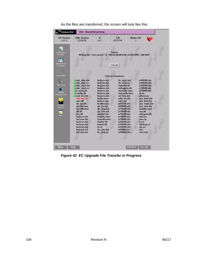
104 Revision N 96217
As the files are transferred, the screen will look like this:
Figure 42 EC Upgrade File Transfer in Progress

96217 Revision N 105
Drive Reconstruction Menu
Figure 43 Drive Reconstruction Menu ScreenThe above is the menu with no drives fenced. If there was a drive fenced, the following screen would be presented instead.
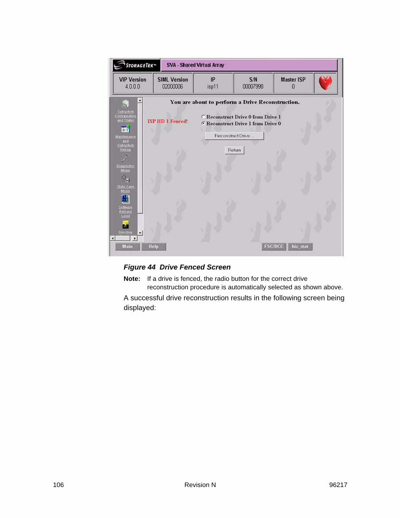
106 Revision N 96217
Figure 44 Drive Fenced ScreenNote: If a drive is fenced, the radio button for the correct drive
reconstruction procedure is automatically selected as shown above.
A successful drive reconstruction results in the following screen being displayed:

96217 Revision N 107
Figure 45 Successful Drive Reconstruction Screen
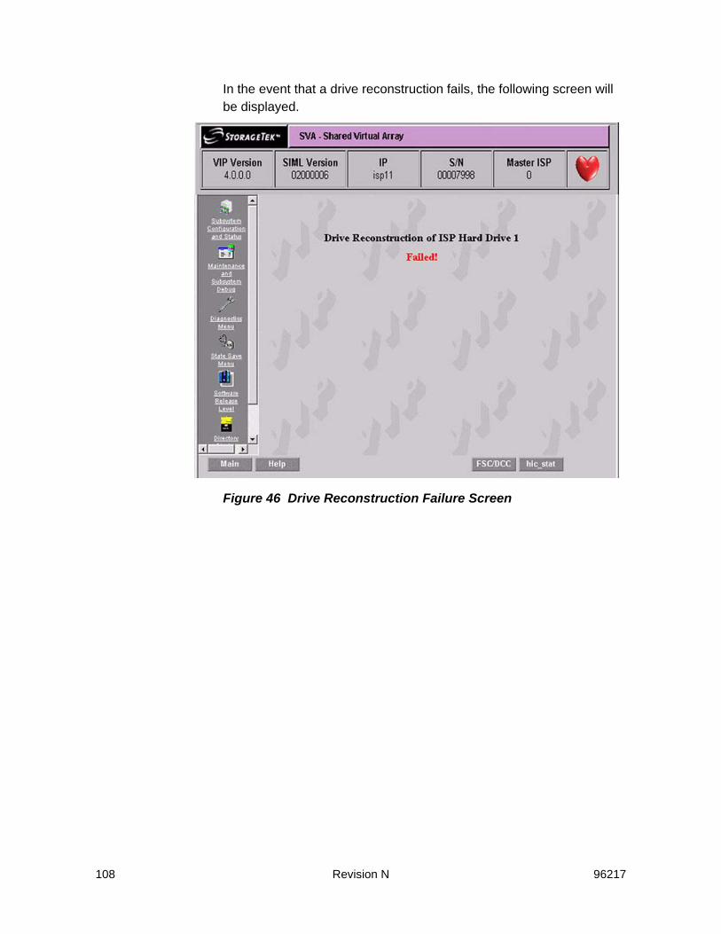
108 Revision N 96217
In the event that a drive reconstruction fails, the following screen will be displayed.
Figure 46 Drive Reconstruction Failure Screen

96217 Revision N 109
If you attempt to connect to the SVA when a Drive Reconstruction is currently in progress, the following screen will be displayed.The Percent Complete is displayed in the upper right box of the Header frame, and the Command in Progress is displayed in the Window Status bar (bottom left of screen).
Figure 47 Connection During Drive Reconstruction Screen
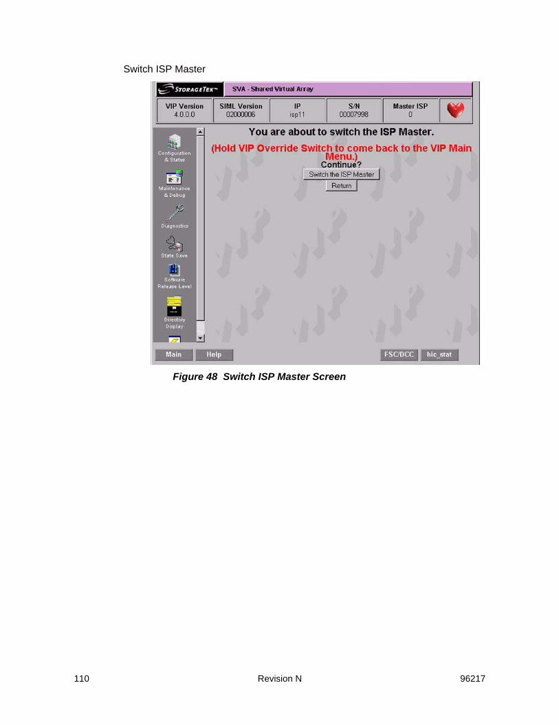
110 Revision N 96217
Switch ISP Master
Figure 48 Switch ISP Master Screen

96217 Revision N 111
Delete Installed Options
Figure 49 Delete Installed Options Screen

112 Revision N 96217
Delete Corrupted DBs in all SRLs
Figure 50 Delete Corrupted Databases in all SRLs Screen

96217 Revision N 113
Reset Frame S/N in Boot Blocks to 0
Figure 51 Reset Frame S/N in Boot Blocks to 0 Screen

114 Revision N 96217
Unfence Hard Drive
Figure 52 Unfence Hard Drive Screen

96217 Revision N 115
Select Software Release Level
Figure 53 VIP Select Software Release Level ScreenAny item selected on this menu will show the results in the bottom portion of this screen.

116 Revision N 96217
Directory Display
Figure 54 VIP Directory Display ScreenFigure 55 on page 117 shows the executable directory. All other directory displays are similar.

96217 Revision N 117
Figure 55 Display Directory Screen Example

118 Revision N 96217
Diagnostic Functions
Figure 56 VIP Diagnostic Menu ScreenNote: The HD Read Diagnostics could take a lot longer than the 20 minutes
indicated on the screen.

96217 Revision N 119
Volume Verification
Figure 57 Volume Verification Screen

120 Revision N 96217
Create pHILE Control Files
Figure 58 Create pHILE Control Files ScreenNote: This screen shows that the operation was successful.

96217 Revision N 121
Check pHILE Volumes
Figure 59 Check pHILE Volumes Screen

122 Revision N 96217
Maintenance Bus Diagnostic Menu
Figure 60 Maintenance Bus Diagnostic Menu ScreenClicking on “Maintenance Bus Diagnostic Menu” of Figure 56 on page 118 brings up the screen of Figure 60. At this time, select either “Run Once,” or “Loop Forever” and then press “Execute.”Note: The first time the VIP program is run, the Status and Test Results
boxes will show “Untested” instead of the current display of FAILED and Failure.
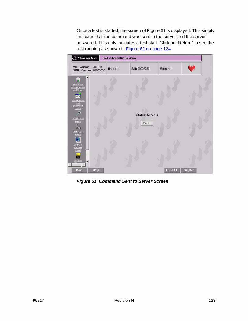
96217 Revision N 123
Once a test is started, the screen of Figure 61 is displayed. This simply indicates that the command was sent to the server and the server answered. This only indicates a test start. Click on “Return” to see the test running as shown in Figure 62 on page 124.
Figure 61 Command Sent to Server Screen

124 Revision N 96217
The screen of Figure 62 shows a test running. A couple of tests have completed and passed, and the rest are pending. Notice that the Status box on the screen shows that the test is running.
Figure 62 Test Running Screen

96217 Revision N 125
Once a test run is complete, the screen of Figure 63 is displayed. Notice that the Status box on the screen indicates the test is complete and the test was successful.
Figure 63 Test Pass Complete ScreenNote: Had the original selection been “Loop Forever,” the Status box would
indicate “Test Is Running.” Clicking on Cancel would stop the looping.

126 Revision N 96217
In the event that an operator logs out of an SVA with a test running, reconnects, and attempts to run another test, the screen of Figure 64 is displayed.
Figure 64 Command in Progress ScreenIf a test was set to “Loop Forever,” the screen of Figure 65 is displayed while the test is running. Click on “Cancel” to stop the testing. Figure

96217 Revision N 127
65 shows that the test has run 17 times and is running for the 18th time.
Figure 65 Test Set to Looping Forever Screen

128 Revision N 96217
State Save Functions
Figure 66 VIP State Save Menu Screen

96217 Revision N 129
Find All State Saves
Figure 67 Find All State Saves Screen
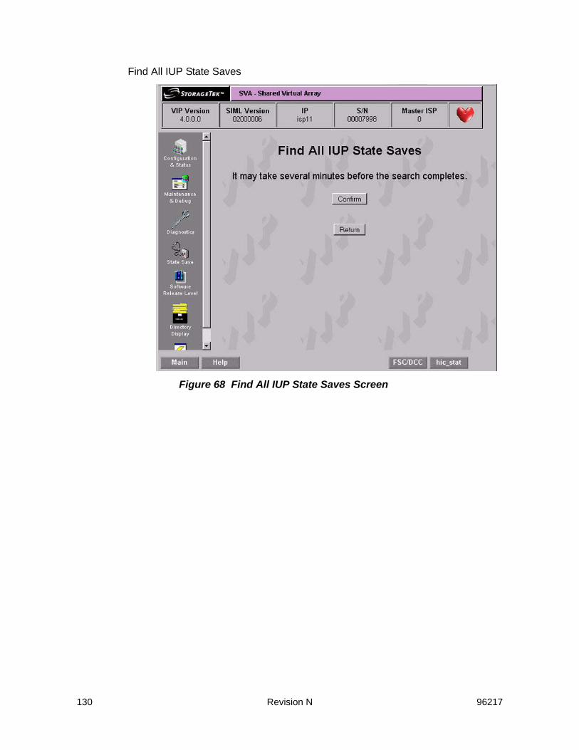
130 Revision N 96217
Find All IUP State Saves
Figure 68 Find All IUP State Saves Screen

96217 Revision N 131
Find All ISP State Saves
Figure 69 Find All ISP State Saves Screen
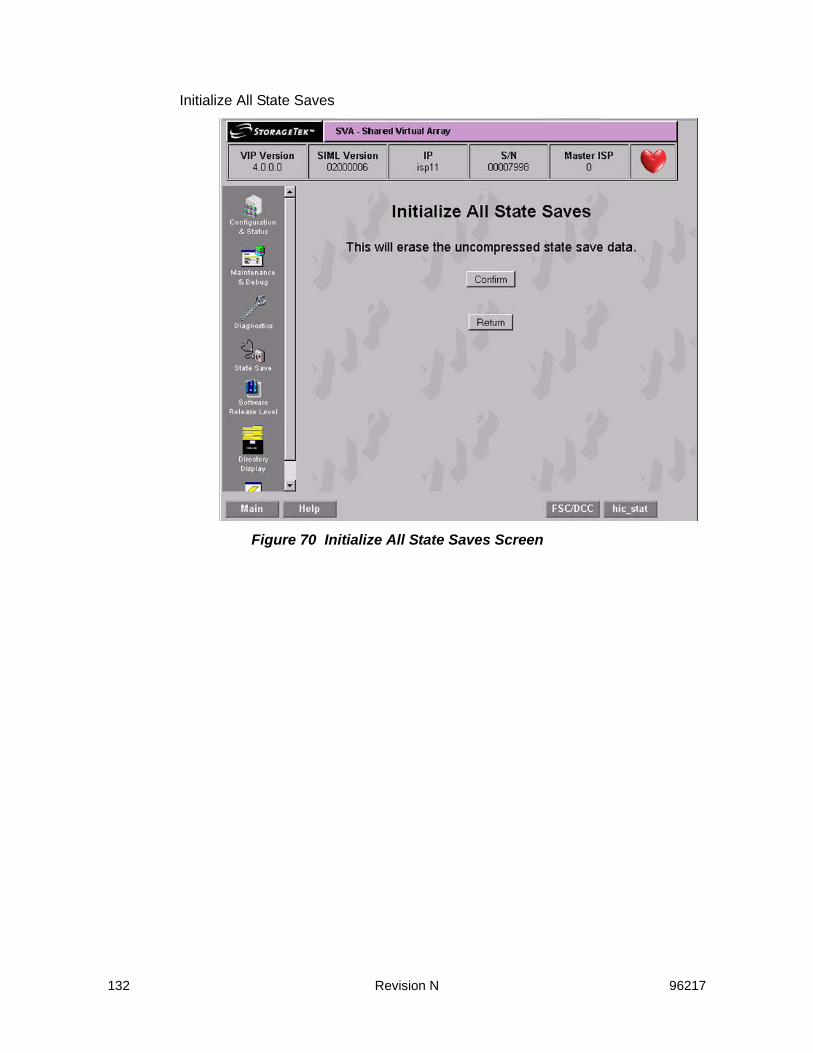
132 Revision N 96217
Initialize All State Saves
Figure 70 Initialize All State Saves Screen

96217 Revision N 133
Initialize All IUP State Saves
Figure 71 Initialize IUP State Saves Screen

134 Revision N 96217
Initialize ISP State Saves
Figure 72 Initialize ISP State Saves Screen

96217 Revision N 135
IML the ISP
Figure 73 VIP IML Selection ScreenThis screen allow you to remotely exit VIP and reboot the SVA without pressing any buttons on the actual SVA. If you click on the “IML in VIP mode (VIP Switch Overide),“ box, putting a check there, the SVA will come back up in VIP mode. While the SVA can be rebooted from a production screen, it cannot be brought up in VIP mode.

136 Revision N 96217

96217 Revision N 137
EDual Fenced Condition
If one of the drives for the ISP cards is “fenced” or otherwise unusable and the usable drive is in the middle of a write operation and there is a complete loss of power to the SVA or the EPO button is pressed, it will render the last usable drive as “fenced.” When power is restored, the SVA will find no usable drives from which to IML.During a normal power down, the SVA finishes all write activity to the hard drives before finally shutting down power, thus avoiding this condition. It is only the sudden loss of power or the use of the EPO button that creates the conditions required to “fence” the drive(s).
IndicationsThis dual “fenced” condition is indicated at power on by:
1. the power up sequence stops without the Power Complete LED illuminating,
2. and the red and green LEDs on the ISP cards flashing.
RecoveryRecovery from the “dual fenced condition” is done with the VIP. Follow this procedure to correct the problem:
1. Reboot the SVA in VIP mode: this is done by holding the switch on the Faceplate Assembly in the VIP position, then pressing the power button.
2. Once VIP starts, there will be a warning message superimposed over the main VIP screen indicating that there is a problem with a
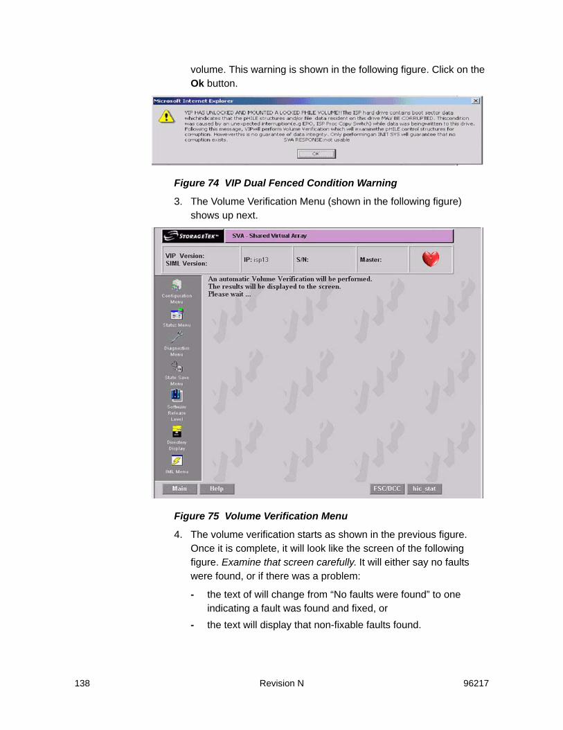
138 Revision N 96217
volume. This warning is shown in the following figure. Click on the Ok button.
Figure 74 VIP Dual Fenced Condition Warning
3. The Volume Verification Menu (shown in the following figure) shows up next.
Figure 75 Volume Verification Menu
4. The volume verification starts as shown in the previous figure. Once it is complete, it will look like the screen of the following figure. Examine that screen carefully. It will either say no faults were found, or if there was a problem:
- the text of will change from “No faults were found” to one indicating a fault was found and fixed, or
- the text will display that non-fixable faults found.
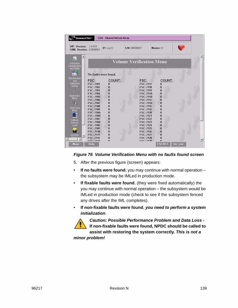
96217 Revision N 139
Figure 76 Volume Verification Menu with no faults found screen
5. After the previous figure (screen) appears:
• If no faults were found, you may continue with normal operation – the subsystem may be IMLed in production mode.
• If fixable faults were found, (they were fixed automatically) the you may continue with normal operation – the subsystem would be IMLed in production mode (check to see if the subsystem fenced any drives after the IML completes).
• If non-fixable faults were found, you need to perform a system initialization.
Caution: Possible Performance Problem and Data Loss - If non-fixable faults were found, NPDC should be called to assist with restoring the system correctly. This is not a
minor problem!

140 Revision N 96217


SUN™ THE NETWORK IS THE COMPUTER ©2006 Sun Microsystems, Inc. All rights reserved. Sun, Sun Microsystems, and the Sun logo are trademarks or registered trademarks of Sun Microsystems, Inc. in theUnited States and other countries.
Sun Microsystems, Inc. 4150 Network Circle, Santa Clara, CA 95054 USA Phone 1-650-960-1300 or 1-800-555-9SUN Web sun.com
ARGENTINA: 5411-4317-5636 • AUSTRALIA: 1-800-550-786 • AUSTRIA: 43-1-601-26-0 • BALKANS: 301-6188-111 • BELGIUM: 32 2-704 89 83 • BRAZIL: 55-11-51872100 • BRUNEI: 65-216-8333 • CANADA: 1-800-422-8020 (GENERAL); 416-964-2001 (LEARNING MANAGEMENT SYSTEM SALES,TORONTO) • CHILE: 562-372-4500 • COLOMBIA: 571-629-2323CZECH REPUBLIC: 420 2 33009311 • DENMARK: 45 4556 5040 • EGYPT: 00 202 570 9442 • FINLAND: 358-9-525-561 • FRANCE: 33-1-41-33-17-17 • GERMANY: 49-89-460-08-2788 • GREECE: 30-01-6188101 • HONG KONG: 852-2877-7077 • HUNGARY: 361-202-4415 • INDIA: 91-80-229-8989 • INDONESIA: 65-216-8333 • IRELAND: 353-1-668-4377ISRAEL: 972-9-9710500 • ITALY: 39-02-9259511 • JAPAN: 81-3-5779-1820 • KOREA: 82-2-3453-6602 • MALAYSIA: 603-2116-1887 • MIDDLE EAST: 00 9714 3366333 • MEXICO: 525-261-0344 • NETHERLANDS: 31-33-4515200 • NEW ZEALAND: 0800-786-338 • NORTH WEST AFRICA: 00 9714 3366333 • NORWAY: FROM NORWAY: 47-22023950, TO NORWAY:47-23369650 • PAKISTAN: 00-9714-3366333 • PEOPLE'S REPUBLIC OF CHINA: 8610-6803-5588 • PHILIPPINES: 632-885-7867 • POLAND: 48-22-8747848 • PORTUGAL: 351-21-413-4000 • RUSSIA: 7-095-935-8411 • SAUDI ARABIA: 00 9714 3366333 • SINGAPORE: 65-216-8300 • SOUTH AFRICA: 27-11-256-6300 • SPAIN: 34-902-210-412 • SRI LANKA:65-2168333 • SWEDEN: 46-8-631 22 00 • SWITZERLAND: 41-1-908-90-50 (GERMAN) 41-22-999-0444 (FRENCH) • TAIWAN: 886-2-25185735 • THAILAND: 662-344-6855 • TURKEY: 90 212 335 22 00 • UNITED KINGDOM: 44-1276-416-520 • UNITED STATES: 1-800-422-8020 • VENEZUELA: 582-905-3800 • VIETNAM: 65-216-8333 • WORLDWIDE
HEADQUARTERS: 1-650-960-1300